US10070753B2 - Cooking chamber frame for a cooking appliance - Google Patents
Cooking chamber frame for a cooking appliance Download PDFInfo
- Publication number
- US10070753B2 US10070753B2 US13/958,674 US201313958674A US10070753B2 US 10070753 B2 US10070753 B2 US 10070753B2 US 201313958674 A US201313958674 A US 201313958674A US 10070753 B2 US10070753 B2 US 10070753B2
- Authority
- US
- United States
- Prior art keywords
- cooking
- guide track
- shaped guide
- chamber frame
- cooking chamber
- Prior art date
- Legal status (The legal status is an assumption and is not a legal conclusion. Google has not performed a legal analysis and makes no representation as to the accuracy of the status listed.)
- Active, expires
Links
Images


Classifications
-
- A—HUMAN NECESSITIES
- A47—FURNITURE; DOMESTIC ARTICLES OR APPLIANCES; COFFEE MILLS; SPICE MILLS; SUCTION CLEANERS IN GENERAL
- A47J—KITCHEN EQUIPMENT; COFFEE MILLS; SPICE MILLS; APPARATUS FOR MAKING BEVERAGES
- A47J37/00—Baking; Roasting; Grilling; Frying
- A47J37/06—Roasters; Grills; Sandwich grills
- A47J37/0611—Roasters; Grills; Sandwich grills the food being cooked between two heating plates, e.g. waffle-irons
- A47J2037/0617—Roasters; Grills; Sandwich grills the food being cooked between two heating plates, e.g. waffle-irons with means to adjust the distance between heating plates
-
- Y—GENERAL TAGGING OF NEW TECHNOLOGICAL DEVELOPMENTS; GENERAL TAGGING OF CROSS-SECTIONAL TECHNOLOGIES SPANNING OVER SEVERAL SECTIONS OF THE IPC; TECHNICAL SUBJECTS COVERED BY FORMER USPC CROSS-REFERENCE ART COLLECTIONS [XRACs] AND DIGESTS
- Y10—TECHNICAL SUBJECTS COVERED BY FORMER USPC
- Y10T—TECHNICAL SUBJECTS COVERED BY FORMER US CLASSIFICATION
- Y10T29/00—Metal working
- Y10T29/49—Method of mechanical manufacture
- Y10T29/49826—Assembling or joining
Definitions
- the present invention relates to cooking appliances and, more particularly, to a cooking chamber frame for a cooking appliance.
- Cooking appliances and in particular electric cooking/grilling devices such as griddles, are known.
- One type of known grilling devices typically evidences a lower housing having a lower cooking surface and an upper housing having an upper cooking surface, wherein the cooking surfaces are typically heated by an electrical resistance heater.
- a handle attached to the upper housing allows a user to raise and lower the upper housing relative to the lower housing to accommodate a food item therebetween to be heated.
- a cooking appliance includes an upper housing, a lower housing operatively connected to the upper housing, and a removable baking attachment received on the lower housing.
- the baking attachment has a bottom surface, a substantially open top and peripheral sidewalls defining a baking cavity.
- a cooking chamber frame for a cooking appliance having an upper heating element operatively connected to a lower heating element.
- the cooking chamber frame includes a substantially planar bottom surface, a substantially open top and peripheral sidewalls defining a cooking cavity therebetween.
- the cooking chamber frame is configured to be received adjacent the lower heating element such that the cooking chamber frame is selectively captured between the upper heating element and the lower heating element.
- a method of configuring a cooking appliance to perform baking functions includes the steps of operatively connecting a first heating surface with a second heating surface such that the first heating surface is positioned in opposition to the second heating surface, and equipping the cooking appliance with a removable baking attachment having a bottom surface, a substantially open top and peripheral sidewalls defining a baking cavity.
- FIG. 1 is a perspective view of a cooking appliance according to an embodiment of the present invention, illustrating the cooking appliance in a closed position.
- FIG. 2 is a perspective view of the cooking appliance of FIG. 1 , illustrating the cooking appliance in a fully open position.
- FIG. 3 is a side elevational view of the cooking appliance of FIG. 1 , illustrating the upper housing of the appliance in a partially elevated position.
- FIG. 4 is a side elevational view of the cooking appliance of FIG. 1 , illustrating the upper housing of the appliance in a substantially vertical, open position.
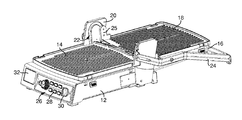
- FIG. 5 is a perspective view of the cooking appliance of FIG. 1 , illustrating use with a cooking chamber frame according to an embodiment of the present invention.
- FIG. 6 is a perspective view of the cooking chamber frame shown in FIG. 5 .
- FIG. 7 is a perspective view of a cake mold for use with the cooking appliance of FIG. 1 and the cooking chamber frame of FIG. 6 .
- FIG. 8 is a perspective view of the cooking appliance of FIG. 1 , illustrating use with the cooking chamber frame and shown in a ‘baking’ position.
- the cooking appliance 10 generally takes the form of a countertop grill and includes a lower housing 12 having a lower heating/cooking plate 14 and an upper housing 16 having an upper heating/cooking plate 18 .
- the upper and lower heating plates 14 , 18 are removable from the upper and lower housing 12 , 16 , respectively, as discussed hereinafter.
- the upper housing 16 is operatively connected to the lower housing 12 via opposed frame members 20 extending from the lower housing 16 .
- the upper housing 16 rides in a guide track 22 in the frame members 20 .
- a handle 24 attached to the upper housing 16 allows a user to raise and lower the upper housing 16 in the guide track 22 in order to selectively position the upper housing 16 in various positions in relation to the lower housing 12 .
- the guide track 22 is substantially ‘n’ shaped and the upper housing 16 is operatively connected to the frame members 20 , via the guide track 22 , through brackets 25 having wheels (not shown) that are received within the guide track 22 .
- the shape of the guide track 22 therefore controls the trajectory of movement of the upper housing 16 relative to the lower housing 12 , allowing the upper housing 16 to be selectively positioned at various orientations relative to the lower housing 12 .
- the upper housing 16 may be closed against the lower housing 12 , as shown in FIG. 1 , oriented in a fully open position, as shown in FIG. 2 , oriented at an elevated position, as shown in FIG. 3 , and oriented in an upright position, as shown in FIG. 4 .
- the upper housing 16 (and upper heating surface 18 ) may be elevated above the lower heating surface 14 while remaining parallel thereto, as best shown in FIG. 3 .
- the cooking appliance 10 includes a control panel 26 having an array of buttons 28 and rotatable knobs 30 that allow a user to select and set a variety of cooking and heating parameters, and an LCD screen 32 that allows a user to view the parameters being set, as well as to monitor the cooking process.
- the cooking appliance 10 also includes a removable baking attachment, such as cooking chamber frame 34 , that is selectively positionable on, and attachable to, the lower housing 12 in the manner discussed below.
- a removable baking attachment such as cooking chamber frame 34
- the cooking chamber frame 34 takes the form of a deep pan that is generally rectangular in shape and has a substantially planar bottom surface 36 and upstanding sidewalls 38 .
- the sidewalls 38 are approximately 2 inches in height. In other embodiments, the sidewalls 38 may be more or less than 2 inches in height.
- the cooking chamber frame 34 is formed from a metal having good heat transfer capabilities to facilitate heat transfer from the heating element (not shown) of the cooking appliance 10 to the food items within the chamber 34 .
- the chamber frame 34 also has a non-stick coating to facilitate cleaning.
- the lower heating plate 14 is removable from the lower housing 12 such that the cooking chamber frame 34 may be installed on the lower housing 12 in place thereof.
- the cooking chamber frame 34 snaps onto the lower housing in the same manner as the lower heating plate 14 , by utilizing biased retaining snaps 40 , as is known in the art.
- a user may first lift up on the handle 24 and position the upper housing 16 in its upright position, as shown in FIGS. 4 and 5 .
- a user may then remove the lower heating plate 14 by releasing the retaining snaps 40 .
- the cooking chamber frame 34 may then be placed on the lower housing 12 above the heating element (not shown).
- a cake mold 42 or other baking tray may then be filled with batter or other food ingredients to be baked and placed within the cooking chamber frame 34 .
- the cooking chamber frame 34 may be filled, itself, with liquid or other ingredients to be baked.
- the upper housing 16 may then be lowered to the position shown in FIG. 8 , such that the lower heating plate 18 contacts the upper edges of the sidewalls 38 of the cooking chamber frame 34 .
- the ‘n’ shape of the guide track 22 allows for vertical movement of the upper heating plate 18 and upper housing 14 , such that the upper heating plate 18 covers the cooking chamber frame 34 to form a baking cavity therebetween.
- the cooking appliance 10 may be utilized with the lower heating plate 12 for grilling and the like and, alternatively, with the chamber 34 for baking. Once arranged for the desired cooking function, a user may set the type of cooking to be carried out utilizing the control panel 26 . As will be readily appreciated, it is therefore possible for the cooking appliance 10 to function not only as a single or double sided grill, Panini press or the like, but also as an oven to perform baking and other similar cooking functions.
Landscapes
- Engineering & Computer Science (AREA)
- Food Science & Technology (AREA)
- Baking, Grill, Roasting (AREA)
Abstract
Description
Claims (17)
Priority Applications (1)
| Application Number | Priority Date | Filing Date | Title |
|---|---|---|---|
| US13/958,674 US10070753B2 (en) | 2013-08-05 | 2013-08-05 | Cooking chamber frame for a cooking appliance |
Applications Claiming Priority (1)
| Application Number | Priority Date | Filing Date | Title |
|---|---|---|---|
| US13/958,674 US10070753B2 (en) | 2013-08-05 | 2013-08-05 | Cooking chamber frame for a cooking appliance |
Publications (2)
| Publication Number | Publication Date |
|---|---|
| US20150033950A1 US20150033950A1 (en) | 2015-02-05 |
| US10070753B2 true US10070753B2 (en) | 2018-09-11 |
Family
ID=52426472
Family Applications (1)
| Application Number | Title | Priority Date | Filing Date |
|---|---|---|---|
| US13/958,674 Active 2034-07-29 US10070753B2 (en) | 2013-08-05 | 2013-08-05 | Cooking chamber frame for a cooking appliance |
Country Status (1)
| Country | Link |
|---|---|
| US (1) | US10070753B2 (en) |
Cited By (1)
| Publication number | Priority date | Publication date | Assignee | Title |
|---|---|---|---|---|
| US20180332999A1 (en) * | 2017-05-22 | 2018-11-22 | Jiangmen City Xinhui Henglong Plastic Co., Ltd. | Multifunctional cooking and baking assembly |
Families Citing this family (1)
| Publication number | Priority date | Publication date | Assignee | Title |
|---|---|---|---|---|
| CN105935260B (en) * | 2016-06-23 | 2018-05-15 | 宁波凯波集团有限公司 | A kind of baking machine of step-less adjustment height |
Citations (40)
| Publication number | Priority date | Publication date | Assignee | Title |
|---|---|---|---|---|
| US2033060A (en) | 1932-04-25 | 1936-03-03 | Griswold Mfg Company | Grill |
| US2057501A (en) | 1934-04-24 | 1936-10-13 | Westinghouse Electric & Mfg Co | Sandwich grill |
| US2607287A (en) | 1949-09-10 | 1952-08-19 | Harry E Price | Electric grill |
| US2719903A (en) | 1952-06-13 | 1955-10-04 | Oertli Traugott | Electric grill |
| US4036995A (en) | 1975-12-29 | 1977-07-19 | Food Automation Service Techniques, Inc. | Oven cooking monitor for uniformly cooking a plurality of food items requiring different cooking times |
| US4088067A (en) | 1976-06-11 | 1978-05-09 | Mcgraw-Edison Company | Cooking appliance |
| US4206345A (en) | 1978-07-24 | 1980-06-03 | Robert Krups | Electrically heatable home appliance |
| US4364308A (en) * | 1976-06-07 | 1982-12-21 | Engineering Inventions, Inc. | Apparatus for preparing food |
| US4697504A (en) | 1985-12-06 | 1987-10-06 | Richard Keating | Hinged top grill arrangment |
| US5154115A (en) * | 1990-05-30 | 1992-10-13 | Leonard Kian | Pizza crust cooking utensil |
| US5237914A (en) | 1992-11-30 | 1993-08-24 | Carstensen Morris A | Cooking grill assembly |
| US5467696A (en) | 1995-01-18 | 1995-11-21 | Everhart; Rick J. | Grease free skillet |
| US5531155A (en) | 1995-10-30 | 1996-07-02 | Specialty Equipment Companies, Inc. | Cooking apparatus for two-sided cooking |
| US5712466A (en) | 1995-10-30 | 1998-01-27 | Spicer; James T. | Perfect steak device |
| US5758568A (en) | 1997-06-11 | 1998-06-02 | Keating Of Chicago, Inc. | Top side cooker having cooking head with gear driven adjustment feet |
| US5848567A (en) | 1998-06-06 | 1998-12-15 | Chiang; Hanh | Cooking device having a base unit with a slidably mounted oil accumulating tray for accumulating dripping oil |
| US5992302A (en) | 1997-11-12 | 1999-11-30 | Trustees Of America's Drive-In Trust | Food cooking apparatus with direct food temperature sensing |
| US6062130A (en) | 1999-04-05 | 2000-05-16 | Hamilton Beach/Proctor-Silex, Inc. | Convertible household electric cooking appliance |
| USD436498S1 (en) | 1999-05-03 | 2001-01-23 | Steven B. Carlson | Grease and debris catcher container design for a barbecue grill upper lid |
| US6192788B1 (en) * | 1999-03-17 | 2001-02-27 | U.S. Philips Corporation | Grilling appliance |
| US6389959B1 (en) | 2001-07-27 | 2002-05-21 | Harold E. Robertson | Multipurpose grill |
| US6439108B1 (en) | 2002-03-25 | 2002-08-27 | Eupa International Corporation | Grill device having a space adjusting unit to adjust a space between an upper grill unit and a lower grill unit |
| US6484624B1 (en) * | 2002-05-14 | 2002-11-26 | Eupa International Corporation | Grill device provided with a seasoning supplying unit |
| USRE37988E1 (en) | 1995-09-22 | 2003-02-18 | Newell Operating Company | Cookware top |
| US6539842B1 (en) | 2002-07-19 | 2003-04-01 | Maverick Industries, Inc. | Rotisserie system having a remote temperature monitor |
| US6591740B1 (en) | 2002-12-06 | 2003-07-15 | Lundar Electric Industrial Co., Ltd. | Barbecue grill with an adjusting device |
| US6595116B1 (en) | 2002-12-09 | 2003-07-22 | Uni-Splendor Corp. | Cooking device |
| US6705306B1 (en) | 2001-08-17 | 2004-03-16 | Thomas J. Dickey | Grill lid positioner |
| US20040074398A1 (en) | 2002-10-18 | 2004-04-22 | R. J. Product Solutions, Inc. | Steak weight with meat thermometer |
| EP1479330A1 (en) * | 2003-05-20 | 2004-11-24 | Seb S.A. | Household appliance with two offset articulated hot plates |
| US20050139086A1 (en) | 2003-07-02 | 2005-06-30 | Mchutchison Bryan | Toaster grill |
| US7514655B2 (en) | 2006-03-07 | 2009-04-07 | Products Of Tomorrow, Inc. | Tiltable pannini grill |
| US20090165774A1 (en) | 2008-01-02 | 2009-07-02 | Char-Broil, Llc | Temperature measurement means for cooking appliances |
| US7608803B2 (en) | 2006-11-14 | 2009-10-27 | Robertshaw Controls Company | Setting oven/grill temperature and/or meat probe using stepper motor analog display |
| US7717028B2 (en) | 2003-10-16 | 2010-05-18 | Breville Pty Limited | Sandwich press and grill |
| US8122816B2 (en) | 2007-12-11 | 2012-02-28 | Tsann Kuen (China) Enterprise Co., Ltd. | Grill with adjustable grilling space |
| US20120090476A1 (en) * | 2006-04-10 | 2012-04-19 | Tsann Kuen(China) Enterprise Co., Ltd. | Griddle with adjustable space between upper and lower pans |
| US20120137897A1 (en) | 2009-05-07 | 2012-06-07 | Eksen Makine Sanayi Ve Ticaret, A.S. | Toasting apparatus with a handle having predetermined locking positions |
| US8336451B2 (en) * | 2008-08-29 | 2012-12-25 | Tsann Kuen (Zhangzhou) Enterprise Co., Ltd. | Grill |
| US20150208862A1 (en) * | 2013-01-14 | 2015-07-30 | Hamilton Beach Brands, Inc. | Sandwich Making Appliance and Method of Making a Sandwich with the Same |
-
2013
- 2013-08-05 US US13/958,674 patent/US10070753B2/en active Active
Patent Citations (41)
| Publication number | Priority date | Publication date | Assignee | Title |
|---|---|---|---|---|
| US2033060A (en) | 1932-04-25 | 1936-03-03 | Griswold Mfg Company | Grill |
| US2057501A (en) | 1934-04-24 | 1936-10-13 | Westinghouse Electric & Mfg Co | Sandwich grill |
| US2607287A (en) | 1949-09-10 | 1952-08-19 | Harry E Price | Electric grill |
| US2719903A (en) | 1952-06-13 | 1955-10-04 | Oertli Traugott | Electric grill |
| US4036995A (en) | 1975-12-29 | 1977-07-19 | Food Automation Service Techniques, Inc. | Oven cooking monitor for uniformly cooking a plurality of food items requiring different cooking times |
| US4364308A (en) * | 1976-06-07 | 1982-12-21 | Engineering Inventions, Inc. | Apparatus for preparing food |
| US4088067A (en) | 1976-06-11 | 1978-05-09 | Mcgraw-Edison Company | Cooking appliance |
| US4206345A (en) | 1978-07-24 | 1980-06-03 | Robert Krups | Electrically heatable home appliance |
| US4697504A (en) | 1985-12-06 | 1987-10-06 | Richard Keating | Hinged top grill arrangment |
| US5154115A (en) * | 1990-05-30 | 1992-10-13 | Leonard Kian | Pizza crust cooking utensil |
| US5237914A (en) | 1992-11-30 | 1993-08-24 | Carstensen Morris A | Cooking grill assembly |
| US5467696A (en) | 1995-01-18 | 1995-11-21 | Everhart; Rick J. | Grease free skillet |
| USRE37988E1 (en) | 1995-09-22 | 2003-02-18 | Newell Operating Company | Cookware top |
| US5531155A (en) | 1995-10-30 | 1996-07-02 | Specialty Equipment Companies, Inc. | Cooking apparatus for two-sided cooking |
| US5712466A (en) | 1995-10-30 | 1998-01-27 | Spicer; James T. | Perfect steak device |
| US5758568A (en) | 1997-06-11 | 1998-06-02 | Keating Of Chicago, Inc. | Top side cooker having cooking head with gear driven adjustment feet |
| US5992302A (en) | 1997-11-12 | 1999-11-30 | Trustees Of America's Drive-In Trust | Food cooking apparatus with direct food temperature sensing |
| US5848567A (en) | 1998-06-06 | 1998-12-15 | Chiang; Hanh | Cooking device having a base unit with a slidably mounted oil accumulating tray for accumulating dripping oil |
| US6192788B1 (en) * | 1999-03-17 | 2001-02-27 | U.S. Philips Corporation | Grilling appliance |
| US6062130A (en) | 1999-04-05 | 2000-05-16 | Hamilton Beach/Proctor-Silex, Inc. | Convertible household electric cooking appliance |
| USD436498S1 (en) | 1999-05-03 | 2001-01-23 | Steven B. Carlson | Grease and debris catcher container design for a barbecue grill upper lid |
| US6389959B1 (en) | 2001-07-27 | 2002-05-21 | Harold E. Robertson | Multipurpose grill |
| US6705306B1 (en) | 2001-08-17 | 2004-03-16 | Thomas J. Dickey | Grill lid positioner |
| US6439108B1 (en) | 2002-03-25 | 2002-08-27 | Eupa International Corporation | Grill device having a space adjusting unit to adjust a space between an upper grill unit and a lower grill unit |
| US6484624B1 (en) * | 2002-05-14 | 2002-11-26 | Eupa International Corporation | Grill device provided with a seasoning supplying unit |
| US6539842B1 (en) | 2002-07-19 | 2003-04-01 | Maverick Industries, Inc. | Rotisserie system having a remote temperature monitor |
| US20040074398A1 (en) | 2002-10-18 | 2004-04-22 | R. J. Product Solutions, Inc. | Steak weight with meat thermometer |
| US6591740B1 (en) | 2002-12-06 | 2003-07-15 | Lundar Electric Industrial Co., Ltd. | Barbecue grill with an adjusting device |
| US6595116B1 (en) | 2002-12-09 | 2003-07-22 | Uni-Splendor Corp. | Cooking device |
| EP1479330A1 (en) * | 2003-05-20 | 2004-11-24 | Seb S.A. | Household appliance with two offset articulated hot plates |
| US20050139086A1 (en) | 2003-07-02 | 2005-06-30 | Mchutchison Bryan | Toaster grill |
| US7717028B2 (en) | 2003-10-16 | 2010-05-18 | Breville Pty Limited | Sandwich press and grill |
| US8261657B2 (en) | 2003-10-16 | 2012-09-11 | Breville Pty Limited | Press and grill |
| US7514655B2 (en) | 2006-03-07 | 2009-04-07 | Products Of Tomorrow, Inc. | Tiltable pannini grill |
| US20120090476A1 (en) * | 2006-04-10 | 2012-04-19 | Tsann Kuen(China) Enterprise Co., Ltd. | Griddle with adjustable space between upper and lower pans |
| US7608803B2 (en) | 2006-11-14 | 2009-10-27 | Robertshaw Controls Company | Setting oven/grill temperature and/or meat probe using stepper motor analog display |
| US8122816B2 (en) | 2007-12-11 | 2012-02-28 | Tsann Kuen (China) Enterprise Co., Ltd. | Grill with adjustable grilling space |
| US20090165774A1 (en) | 2008-01-02 | 2009-07-02 | Char-Broil, Llc | Temperature measurement means for cooking appliances |
| US8336451B2 (en) * | 2008-08-29 | 2012-12-25 | Tsann Kuen (Zhangzhou) Enterprise Co., Ltd. | Grill |
| US20120137897A1 (en) | 2009-05-07 | 2012-06-07 | Eksen Makine Sanayi Ve Ticaret, A.S. | Toasting apparatus with a handle having predetermined locking positions |
| US20150208862A1 (en) * | 2013-01-14 | 2015-07-30 | Hamilton Beach Brands, Inc. | Sandwich Making Appliance and Method of Making a Sandwich with the Same |
Non-Patent Citations (1)
| Title |
|---|
| WO 2008/043127 (Robinson et al) Apr. 2008. * |
Cited By (2)
| Publication number | Priority date | Publication date | Assignee | Title |
|---|---|---|---|---|
| US20180332999A1 (en) * | 2017-05-22 | 2018-11-22 | Jiangmen City Xinhui Henglong Plastic Co., Ltd. | Multifunctional cooking and baking assembly |
| US10743709B2 (en) * | 2017-05-22 | 2020-08-18 | Jiangmen City Xinhui Henglong Innovative Housewares Co., Ltd. | Multifunctional cooking and baking assembly |
Also Published As
| Publication number | Publication date |
|---|---|
| US20150033950A1 (en) | 2015-02-05 |
Similar Documents
| Publication | Publication Date | Title |
|---|---|---|
| US8656828B2 (en) | Electric oven for cooking food | |
| US10085591B2 (en) | Method of containing splatter in a cooking appliance | |
| EP2133013B1 (en) | Multi-purpose cooking appliance | |
| US20210274968A1 (en) | Cooking appliance with conductive heating capabilities | |
| MX2007006407A (en) | Cooking appliance. | |
| US20210106173A1 (en) | Smoke reduction system for a cooking appliance | |
| US6621053B1 (en) | Toaster oven rack | |
| CN204600239U (en) | Multifunctional cooking electric oven | |
| US7228792B2 (en) | Cooker with latching drip tray for selectively opening and closing grease dispensing apertures in cooking pan | |
| US12035844B2 (en) | Toaster oven system and method | |
| DE202013101408U1 (en) | An electromagnetic grill device | |
| US10070753B2 (en) | Cooking chamber frame for a cooking appliance | |
| KR101641461B1 (en) | Hybrid heating cooker with electric and charcoal fire plate function | |
| US8439028B2 (en) | Cooking appliance with an oven rack | |
| CN207755118U (en) | A kind of electric oven of easy cleaning | |
| CN211582729U (en) | Grill assembly of barbecue electric appliance and barbecue electric appliance thereof | |
| WO2017118623A1 (en) | A toaster | |
| CN216932801U (en) | Baking tray assembly for cooking appliance and cooking appliance | |
| EP1892475A2 (en) | Oven rack and drip pan assembly | |
| JP2015198758A (en) | Cooker | |
| KR20160015103A (en) | Rice Burger-forming device | |
| CN204016024U (en) | A kind of cooking apparatus and the splash guard for this cooking apparatus | |
| US9377205B2 (en) | Oven rack | |
| US9565971B2 (en) | Food mounting assembly for a cooking appliance | |
| EP2772694A1 (en) | Method for supporting a container in an oven and oven for its implementation |
Legal Events
| Date | Code | Title | Description |
|---|---|---|---|
| AS | Assignment |
Owner name: CONAIR CORPORATION, CONNECTICUT Free format text: ASSIGNMENT OF ASSIGNORS INTEREST;ASSIGNORS:FUNG, KAM FAI;LAI, KIN MAN;REEL/FRAME:031458/0657 Effective date: 20130913 |
|
| STCF | Information on status: patent grant |
Free format text: PATENTED CASE |
|
| AS | Assignment |
Owner name: CONAIR LLC, CONNECTICUT Free format text: ASSIGNMENT OF ASSIGNORS INTEREST;ASSIGNOR:CONAIR CORPORATION;REEL/FRAME:057216/0011 Effective date: 20210512 |
|
| AS | Assignment |
Owner name: BANK OF AMERICA, N.A., AS ADMINISTRATIVE AGENT, NORTH CAROLINA Free format text: SECURITY INTEREST;ASSIGNOR:CONAIR LLC;REEL/FRAME:056336/0230 Effective date: 20210517 Owner name: BANK OF AMERICA, N.A., AS ADMINISTRATIVE AGENT, NORTH CAROLINA Free format text: SECURITY INTEREST;ASSIGNOR:CONAIR LLC;REEL/FRAME:056336/0166 Effective date: 20210517 Owner name: OWL ROCK CAPITAL CORPORATION, AS ADMINISTRATIVE AGENT, NEW YORK Free format text: SECURITY INTEREST;ASSIGNOR:CONAIR LLC;REEL/FRAME:056336/0098 Effective date: 20210517 |
|
| MAFP | Maintenance fee payment |
Free format text: PAYMENT OF MAINTENANCE FEE, 4TH YEAR, LARGE ENTITY (ORIGINAL EVENT CODE: M1551); ENTITY STATUS OF PATENT OWNER: LARGE ENTITY Year of fee payment: 4 |
|
| MAFP | Maintenance fee payment |
Free format text: PAYMENT OF MAINTENANCE FEE, 8TH YEAR, LARGE ENTITY (ORIGINAL EVENT CODE: M1552); ENTITY STATUS OF PATENT OWNER: LARGE ENTITY Year of fee payment: 8 |