US10070593B2 - Green horticultural therapy apparatus - Google Patents
Green horticultural therapy apparatus Download PDFInfo
- Publication number
- US10070593B2 US10070593B2 US14/840,754 US201514840754A US10070593B2 US 10070593 B2 US10070593 B2 US 10070593B2 US 201514840754 A US201514840754 A US 201514840754A US 10070593 B2 US10070593 B2 US 10070593B2
- Authority
- US
- United States
- Prior art keywords
- vessel
- interior cavity
- therapy apparatus
- support structure
- gutter
- Prior art date
- Legal status (The legal status is an assumption and is not a legal conclusion. Google has not performed a legal analysis and makes no representation as to the accuracy of the status listed.)
- Active, expires
Links
- 238000009249 horticultural therapy Methods 0.000 title claims abstract description 36
- XLYOFNOQVPJJNP-UHFFFAOYSA-N water Substances O XLYOFNOQVPJJNP-UHFFFAOYSA-N 0.000 claims description 26
- 239000000463 material Substances 0.000 claims description 16
- 239000004033 plastic Substances 0.000 claims description 10
- 239000000203 mixture Substances 0.000 claims description 8
- 241000238631 Hexapoda Species 0.000 claims description 5
- 230000002538 fungal effect Effects 0.000 claims description 3
- 230000001580 bacterial effect Effects 0.000 claims description 2
- 230000001771 impaired effect Effects 0.000 abstract description 9
- 239000002184 metal Substances 0.000 description 18
- 230000003028 elevating effect Effects 0.000 description 8
- 238000013461 design Methods 0.000 description 7
- 238000004064 recycling Methods 0.000 description 7
- 238000013459 approach Methods 0.000 description 6
- 238000000034 method Methods 0.000 description 6
- 239000012530 fluid Substances 0.000 description 4
- 238000010413 gardening Methods 0.000 description 4
- 230000002262 irrigation Effects 0.000 description 4
- 238000003973 irrigation Methods 0.000 description 4
- 239000002689 soil Substances 0.000 description 4
- 230000006378 damage Effects 0.000 description 3
- 230000000694 effects Effects 0.000 description 3
- 238000009408 flooring Methods 0.000 description 3
- 239000007788 liquid Substances 0.000 description 3
- 238000012986 modification Methods 0.000 description 3
- 230000004048 modification Effects 0.000 description 3
- 238000011084 recovery Methods 0.000 description 3
- 238000002560 therapeutic procedure Methods 0.000 description 3
- 241000894006 Bacteria Species 0.000 description 2
- 241000233866 Fungi Species 0.000 description 2
- 241001465754 Metazoa Species 0.000 description 2
- 239000011324 bead Substances 0.000 description 2
- 230000008901 benefit Effects 0.000 description 2
- 239000003086 colorant Substances 0.000 description 2
- 239000011152 fibreglass Substances 0.000 description 2
- 238000010438 heat treatment Methods 0.000 description 2
- 239000002609 medium Substances 0.000 description 2
- 235000015097 nutrients Nutrition 0.000 description 2
- 238000001584 occupational therapy Methods 0.000 description 2
- 238000009252 recreational therapy Methods 0.000 description 2
- 238000003466 welding Methods 0.000 description 2
- 238000010521 absorption reaction Methods 0.000 description 1
- 230000009286 beneficial effect Effects 0.000 description 1
- 239000004568 cement Substances 0.000 description 1
- 239000000470 constituent Substances 0.000 description 1
- 238000011161 development Methods 0.000 description 1
- 230000005611 electricity Effects 0.000 description 1
- 238000001125 extrusion Methods 0.000 description 1
- 210000000245 forearm Anatomy 0.000 description 1
- -1 gravel Substances 0.000 description 1
- 239000001963 growth medium Substances 0.000 description 1
- 238000005286 illumination Methods 0.000 description 1
- 238000010348 incorporation Methods 0.000 description 1
- 239000004615 ingredient Substances 0.000 description 1
- 229910052500 inorganic mineral Inorganic materials 0.000 description 1
- 230000001788 irregular Effects 0.000 description 1
- 238000012423 maintenance Methods 0.000 description 1
- 238000004519 manufacturing process Methods 0.000 description 1
- 239000011707 mineral Substances 0.000 description 1
- 230000004770 neurodegeneration Effects 0.000 description 1
- 208000015122 neurodegenerative disease Diseases 0.000 description 1
- 230000029553 photosynthesis Effects 0.000 description 1
- 238000010672 photosynthesis Methods 0.000 description 1
- 238000000554 physical therapy Methods 0.000 description 1
- 238000011160 research Methods 0.000 description 1
- 230000000284 resting effect Effects 0.000 description 1
- 238000007789 sealing Methods 0.000 description 1
- 210000000278 spinal cord Anatomy 0.000 description 1
- 230000006641 stabilisation Effects 0.000 description 1
- 238000011105 stabilization Methods 0.000 description 1
- 230000000087 stabilizing effect Effects 0.000 description 1
- 239000000126 substance Substances 0.000 description 1
- 238000009966 trimming Methods 0.000 description 1
- 238000010792 warming Methods 0.000 description 1
Images


Classifications
-
- A—HUMAN NECESSITIES
- A01—AGRICULTURE; FORESTRY; ANIMAL HUSBANDRY; HUNTING; TRAPPING; FISHING
- A01G—HORTICULTURE; CULTIVATION OF VEGETABLES, FLOWERS, RICE, FRUIT, VINES, HOPS OR SEAWEED; FORESTRY; WATERING
- A01G9/00—Cultivation in receptacles, forcing-frames or greenhouses; Edging for beds, lawn or the like
- A01G9/02—Receptacles, e.g. flower-pots or boxes; Glasses for cultivating flowers
-
- A—HUMAN NECESSITIES
- A01—AGRICULTURE; FORESTRY; ANIMAL HUSBANDRY; HUNTING; TRAPPING; FISHING
- A01G—HORTICULTURE; CULTIVATION OF VEGETABLES, FLOWERS, RICE, FRUIT, VINES, HOPS OR SEAWEED; FORESTRY; WATERING
- A01G9/00—Cultivation in receptacles, forcing-frames or greenhouses; Edging for beds, lawn or the like
- A01G9/14—Greenhouses
- A01G9/1423—Greenhouse bench structures
-
- A—HUMAN NECESSITIES
- A01—AGRICULTURE; FORESTRY; ANIMAL HUSBANDRY; HUNTING; TRAPPING; FISHING
- A01G—HORTICULTURE; CULTIVATION OF VEGETABLES, FLOWERS, RICE, FRUIT, VINES, HOPS OR SEAWEED; FORESTRY; WATERING
- A01G9/00—Cultivation in receptacles, forcing-frames or greenhouses; Edging for beds, lawn or the like
- A01G9/14—Greenhouses
- A01G9/16—Dismountable or portable greenhouses ; Greenhouses with sliding roofs
-
- Y—GENERAL TAGGING OF NEW TECHNOLOGICAL DEVELOPMENTS; GENERAL TAGGING OF CROSS-SECTIONAL TECHNOLOGIES SPANNING OVER SEVERAL SECTIONS OF THE IPC; TECHNICAL SUBJECTS COVERED BY FORMER USPC CROSS-REFERENCE ART COLLECTIONS [XRACs] AND DIGESTS
- Y02—TECHNOLOGIES OR APPLICATIONS FOR MITIGATION OR ADAPTATION AGAINST CLIMATE CHANGE
- Y02A—TECHNOLOGIES FOR ADAPTATION TO CLIMATE CHANGE
- Y02A40/00—Adaptation technologies in agriculture, forestry, livestock or agroalimentary production
- Y02A40/10—Adaptation technologies in agriculture, forestry, livestock or agroalimentary production in agriculture
- Y02A40/25—Greenhouse technology, e.g. cooling systems therefor
-
- Y02A40/254—
Definitions
- the present invention relates generally to a horticultural therapy apparatus. More particularly, the invention is directed toward an elevated vessel for use by persons with limited mobility and by persons in wheelchairs or other mobility devices.
- Planters are well known in the agricultural and gardening fields. Some planters known in the prior are, such as that described in U.S. Pat. No. 4,825,588 issued to Norman, include a central trough member supported by upstanding wall members. Plants are grown in a medium (usually soil) in the trough. By elevating the plants and media above the ground, the planter protects the plants from insects and ground animals, as well as from foot traffic and moderate flooding. Practitioners in the art have also found that use of a planter allows the practitioner more effectively and easily to control the composition and ingredients of the medium in which the plants are grown.
- Planters offer particular advantages to those practitioners who occupy wheelchairs. If the planter is of proper elevation and is wheelchair-accessible, then the planter allows a practitioner who occupies a wheelchair to tend to the plants without having to bend or stoop. However, traditional planters are not designed for easy use by handicapped persons, particularly persons occupying wheelchairs. Thus, a need is felt for a planter that is designed to be wheelchair-accessible.
- irrigation structures can supply the plants in the planter with controlled amounts of water at regular intervals; in this way an irrigation structure relieves the practitioner of the burden of manually watering the plants and of the risk of depending upon local weather conditions for irregular rain.
- Special lighting structures (hereinafter “grow lights”) can illuminate the plants, supplying the light necessary for photosynthesis. Heaters can help maintain the ambient temperature within the planter, insulating the plants from cold weather.
- Adding some or all of these structures to a planter increases the degree of control that the practitioner exercises over the conditions under which the plants grow. Adding some or all of these structures is also of benefit to a wheelchair-bound practitioner, as the wheelchair-bound practitioner may find it more difficult to perform personally some of the tasks (such as watering plants) accomplished by these structures.
- the addition of irrigating, illuminating, or heating structures requires specialized modification of the planter. In other words, these structures are standard components of most planters, and most planters are not designed with a view to incorporating these structures. Additionally, the specialized modification of a planter to incorporate these structures can be expensive.
- the '568 patent issued to Conklin describes a trough-shaped box.
- This trough-shaped box is composed of a piece of sheet metal bent at its ends partly around two circular wooden discs, which form the end walls of the trough.
- the box is secured to the wooden discs by screws or other suitable fasteners.
- the '588 patent issued to Norman describes an apparatus and method of manufacture wherein a corrugated fiberglass trough is sealed between matching end walls, said walls consisting of stand and plug members which have sealing surfaces which match the contour of the fiberglass trough.
- the '367 patent issued to Huang discloses an artistic flower planting case hangable on a building terrace having a flower planting case and a hanging plate.
- the hanging plate is channel shaped and placed on an upper surface of a terrace wall of a building.
- the flower planting case is an elongated case with an upper open side, forming an interior for soil and flowers.
- the case is assembled with the hanging plate by bolts screwing into a plurality of threaded holes in a rear side of the flower planting case and a front side of the hanging plate.
- the '895 patent issued to Sinanan describes a planter assembly that includes a planter box and a support structure for the planter box.
- the support structure is formed by an elevating post, a base beneath the post and a planter box support atop the post.
- the post is releasably secured within the support structure which enables height adjustment trimming and then refitting of the post with the support structure.
- the '985 patent issued to Miller describes an automatic watering system.
- the device of the 985 patent includes a variety of interconnecting parts to form one or more separate elongate trays which are arrange in any fashion but generally one above the next.
- Each linear or radial tray section is adapted for supporting one or more potted plants.
- Trays are interconnected by flexible tubes so that when water is introduced into an upper tray it flows downwardly into subsequent lower trays. Trays are inexpensively fabricated by an extrusion process and when attached at both ends to end sections, form a finished shelf into which water may be introduced so as to hydrate and feed the plants by root absorption.
- the end sections are held in place by a snap on cover which also engages a screen to provide an effective watering tray and a clog free system.
- a horticultural therapy apparatus comprises a planter designed so that a wheelchair-bound practitioner may access the planter and tend to plants.
- the planter is readily assembled from pieces that can be supplied to consumers in the form of a kit.
- the planter includes structures for illuminating, irrigating, and warming plants grown in the planter, as well as draining structures for removing excess water.
- a horticultural therapy apparatus accommodating persons using a wheelchair or other mobility devices utilized by the disabled encompasses a rounded concave vessel to hold plants and to hold growing media or mixture; and a support structure for elevating said vessel, said support structure including substantially horizontal metal support beams and substantially vertical metal support beams, said support structure including support bands on an underside of said rounded concave vessel, said vessel including design molded horizontal lips that substantially cover said substantially horizontal metal support beams, said vessel being fabricated from a thermally insulating synthetic plastic materials mix, said horizontal lips and said vertical lips having a rough surface texture adapted to inhibit slipping, said support structure elevating said vessel to such a height as to allow a person occupying a mobility device or wheelchair to approach said vessel and physically position the legs of a person and a portion of a mobility device or wheelchair substantially beneath said vessel, thereby enabling tending to activities within said vessel.
- the horticultural therapy apparatus includes a detachable water recycling system.
- the horticultural therapy apparatus further comprising a canopy.
- said support structure further comprises multiple legs, thereby providing safe and sturdy support.
- said support structure further comprises wheels at the base of said legs.
- said vessel is fabricated from a material selected for its resistance to liquid leeching.
- said vessel presents a color selected to repel insects and inhibit fungal growth, bacterial growth, and mold growth.
- Example embodiments of the present general inventive concept can be achieved by a horticultural therapy apparatus accommodating persons using a wheelchair or other mobility devices utilized by the disabled, including a rounded concave vessel to hold plants and to hold growing media or mixture, said rounded concave vessel being fabricated from a thermally insulating synthetic plastic material, said thermally insulating synthetic plastic material being nonporous; and a mobile support structure to elevate said vessel, said support structure being capable of elevating said vessel to multiple elevations, said support structure enabling an operator to adjust the elevation of said vessel, said support structure including substantially horizontal metal support beams, substantially vertical metal support beams, and gussets, said substantially horizontal metal support beams, substantially vertical metal support beams, and gussets being joined by seamless continuous bead welding, said vessel including design molded horizontal lips that substantially cover said substantially horizontal metal support beams and design molded vertical lips that substantially cover said substantially vertical metal support beams, said horizontal lips and said vertical lips having a non-abrasive surface texture adapted to inhibit slipping, said support structure elev
- the horticultural therapy apparatus includes a detachable fluid recycling system.
- the horticultural therapy apparatus includes a canopy.
- said support structure further comprises multiple legs, thereby providing safe and sturdy support.
- said support structure further comprises locking casters at the base of said legs.
- FIG. 1 is a perspective view of one embodiment of the invention, showing a planter with its canopy in the “closed” position;
- FIG. 2 is a perspective view of one embodiment of the invention, showing the planter with its canopy in the raised or “open” position, revealing the plants growing in the trough;
- FIG. 3 is an elevation view of one embodiment of the invention.
- FIG. 4 is an elevation view from one end of the planter, showing the canopy raised on hinges in the open position;
- FIG. 5 is a perspective view of the planter's support apparatus, showing the brackets that secure the support apparatus;
- FIG. 6 is an elevation view of one end of the planter, showing a heater on one end of the planter and heaters on the underside of the trough;
- FIG. 7 is a plan view of the interior of the canopy, showing heaters and an illumination structure
- FIG. 8 is a bottom view of the planter trough, showing drainage holes
- FIG. 9 is an elevation view of the planter showing a pipe along the bottom of the planter that collects water from the drainage holes and carries the water to the bucket hanging from the pipe;
- FIG. 10 is a close-up view of the irrigation pipe running along the inside rim of the trough
- FIG. 11 is a perspective view of the planter with wheels
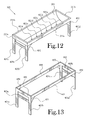
- FIG. 12 is a perspective view of one embodiment of the present invention.
- FIG. 13 is a perspective view of the support structure for the embodiment shown in FIG. 12 ;
- FIG. 14 is a perspective view of the embodiment shown in FIG. 12 , viewed from an elevation lower than the elevation of the vessel;
- FIG. 15 is a side view of the embodiment shown in FIG. 12 , showing the detachable water recovery system
- FIG. 16A is a view of the cross-section shape of the vessel of the embodiment shown in FIG. 12 , showing how the shaped vessel lowers onto the beams of the support structure;
- FIG. 16B is a view of the cross-section shape of the vessel of the embodiment shown in FIG. 12 , showing the vessel in place after being lowered onto the beams of the support structure;
- FIG. 17 is a view of the underside of the vessel of the embodiment shown in FIG. 12 .
- the present invention provides a wheelchair-accessible horticultural therapy apparatus.
- the invention also incorporates illuminating, irrigating and heating structures.
- the invention is supplied to practitioners as parts in a kit. The practitioner then easily, quickly and inexpensively assembles the apparatus with the improvements already installed in an apparatus specially designed to integrate all of these structures.
- a planter with a retractable canopy.
- a planter is indicated generally at 10 .
- the planter includes a substantially tubular trough 20 and a canopy 30 .
- the canopy 30 lies on top of the trough 20 .
- the trough 20 and canopy 30 together constitute a cylindrical structure when the canopy 30 is in the “closed” position, resting atop and covering the trough 20 .
- End walls 22 for the trough 20 and similar end walls 32 for the canopy 30 provide the substantially flat (non-curving) faces of the cylinder.
- the trough 20 normally is fabricated from plastic, a light-weight metal, or a similar substance of sufficient structural strength to support and contain plants and soil or other growth media.
- the canopy 30 is fabricated from a translucent material so as to admit sunlight, as with the walls of a greenhouse.
- the canopy 30 retracts to reveal plants growing in media in the trough 20 .
- one or more handles 34 on the canopy 30 assist the practitioner in raising the canopy from the “closed” position shown in FIG. 1 to the “open” position shown in FIG. 2 .
- the canopy switches between the “closed” and “open” positions by pivoting on one or more hinges 36 .
- a practitioner In the “open” position, a practitioner has access to the interior of the planter 10 and to the plants growing in the trough 20 .
- the practitioner In the “open” position, the practitioner is able to tend to the plants or to perform maintenance on the planter components.
- People familiar with the art will recognize that the degree to which the canopy must be raised in order for the practitioner to perform certain tasks will vary depending upon the practitioner, and therefore the degree to which the canopy is raised may vary, and so numerous “open” positions may exist.
- the trough 20 is raised above the ground by a number of legs 42 .
- the legs 42 are part of a larger support structure 40 , which supports the trough 20 , canopy 30 , and other components of the planter that are elevated off the ground.
- the support structure 40 in addition to the legs 42 , also includes beams 44 in a substantially horizontal orientation.
- the trough 20 rests upon or is otherwise connected to these beams 44 .
- the various constituent parts of the support structure 40 including the legs 42 and the beams 44 , are connected and held in place by braces 46 .
- wheels or rollers 48 attached to the bases of legs make the planter more mobile, as seen in FIG. 11 .
- the support structure 40 elevates the trough 20 above the ground to a height such that a person occupying a wheelchair may approach the planter and position the legs of said person and a portion of the wheelchair substantially beneath the trough 20 .
- Heaters help to maintain within the planter a temperature conducive to growing plants.
- heaters 50 are connected to the underside of the trough 20 .
- one or more heaters 52 are also connected to the end wall 22 of the trough.
- Wires 70 connect the heaters to a power source.
- heaters 54 are connected to the interior/underside (concave side) of the canopy 30 .
- Wires 72 connect the canopy heaters to a power source.
- a light source provides light for the plants when sunlight is not available or practicable.
- one or more electric lamps 60 are connected to the underside of the canopy 30 .
- the electric lamps 60 are connected to a power source through wires 70 .
- Similar wires supply power to those electrically-powered structures connected to the trough 20 .
- said canopy wires 70 are connected to one or more wires 70 that link the canopy wires 70 to wires leading to the a power source.
- the wires collectively convey electrical power drawn either from an external power source or from solar panels 92 , seen in FIG. 11 .
- Irrigation structures provide water to the plants growing within the trough 20 .
- one or more tubes 80 line the rim of the trough 20 . Water flows through the tubes 80 , and said water is released through holes in the tubes 80 into the space where plants are growing in the trough.
- a pump 90 connected to the trough 20 or close nearby supplies water to the tubes 80 , drawing the water from an external water source (such as a well or a garden hose connected to a residential water supply).
- Solar panels 92 or an external power source supply electricity to the pump 90 .
- apertures 82 in the trough 20 allow excess water to drain from the trough.
- a gutter 84 suspended or positioned beneath the trough 20 collects the water flowing from the apertures 82 .
- the gutter 84 then channels the water into a collection bucket 86 that hangs from the trough 20 or support structure 40 .
- the depending sides 21 of the trough 20 are designed to extend over the beams 44 on opposite sides of the support structure 40 .
- the support structure 40 is braced and the elongated beams are substantially covered by the depending sides or lips 21 on the opposite sides of the trough 20 .
- FIG. 6 shows the opening 23 which receives the beams 44 for mounting the trough 20 on the support structure.
- the support structure 40 beams 44 at the opposite ends of the support structure are likewise received behind the depending lips 21 in the openings 23 defined between the end walls 22 of the trough 20 and the depending sides or lips 21 of the trough.
- the openings 23 see FIG.
- All of the components described above can be supplied to consumers in the form of a kit, allowing a practitioner to assemble the apparatus from pieces prefabricated for inclusion in the assembled invention.
- FIGS. 12-17 illustrate one embodiment of the present invention.
- a horticultural therapy apparatus 101 includes a vessel 201 for holding growing media and plants; in this embodiment, the vessel 201 has a substantially rounded and concave shape, substantially like the cross-section of a cylinder cut along its axis.
- the vessel 201 thus has an end component and end edge at each end 221 a and 221 b of its longitudinal axis, as well as two side edges 231 a and 231 b.
- the vessel 201 is supported by a support structure, shown in FIG. 13 , that includes support beams 441 , 442 , 443 , 444 onto which the vessel 201 is mounted; the support beams 441 , 442 , 443 , 444 are supported by a number of legs 401 a - d ; a pair of stabilizing cross-beams 403 a and 403 b , one at either longitudinal end 221 a and 221 b , add stability to the support structure; and braces 451 , 452 , 453 , 454 help to secure the legs 401 a - d to the side support beams 443 and 444 on the side edges 231 a and 231 b and further enhance the stability of the support structure.
- a support structure shown in FIG. 13 , that includes support beams 441 , 442 , 443 , 444 onto which the vessel 201 is mounted; the support beams 441 , 442 , 443 , 444 are supported by
- a number of support bands 270 a - c help to support the vessel 201 .
- the support structure elevates the vessel to a such a height as to allow a person occupying a wheelchair to approach the vessel and personally manipulate the contents of the vessel, while leaving a substantially unobstructed space beneath the vessel of sufficient size to allow a person occupying a wheelchair to approach the planter and position the legs of the person and a portion of the wheelchair substantially beneath the vessel.
- the four legs 401 a - d positioned at the perimeter corners of the apparatus, provide enhanced stability, so that, for example, it is unlikely that a user will tip over the vessel 201 by leaning on an edge of the vessel 201 .
- the vessel 201 includes lips 261 , as seen in FIG. 15 ; these lips 261 substantially cover the horizontal metal support beams 441 , 442 , 443 , 444 .
- the lips of the vessel have a rough surface texture adapted to inhibit slipping, so that when a seated person with limited upper body strength or limited motor control rests the person's forearms or elbows on the lip, the lip is not slippery and provides a stable surface for the person.
- the edges and corners of the apparatus are rounded in order to prevent a user from becoming injured from contact with sharp edges or corners.
- the vessel is fabricated from a thermally insulating plastic that generally will not become uncomfortably hot to the touch when exposed to sunlight for prolonged periods.
- wheels or casters attached to the bases of legs make the apparatus more mobile.
- these and other features of the apparatus collectively provide an elevated, stable and safe working surface that can be easily accessed by a person in a wheelchair or by a person otherwise operating with impaired or limited mobility.
- the vessel 201 is fabricated from a plastic or similar material that inhibits leeching.
- the vessel includes drain apertures 821 a - f that allow excess water to flow out through the bottom of the vessel 201 ; the water, which in many cases has absorbed many minerals and plant nutrients, then flows along a collection gutter 841 to a collection point, where, in many embodiments, it is collected in a bucket or in some other water recycling device or system (hereinafter “water recovery system”) for reintroduction, when needed, to the plants in the vessel 201 .
- this water recovery system is readily detachable from the vessel 201 and the rest of the apparatus.
- FIG. 16A is a view of the cross-section shape of the vessel 201 of the embodiment shown in FIGS. 12-17 , showing how the shaped vessel 201 lowers onto the beams of the support structure 443 , 444 , with the lip 261 of the vessel covering the beams of the support structure; and FIG. 16B is a view of the vessel 201 in place after being lowered onto the beams of the support structure.
- the vessel 201 is red or is a color that deters insects and inhibits fungal growth.
- the present general inventive concept comprises a horticultural therapy apparatus primarily designed for use in an environment of physical therapy (PT), sub-classed as occupational therapy (OT), with a further refined designation, as a specialty category, of recreational therapy (RT), within which there is a highly specialized focus of horticultural therapy (HT).
- PT physical therapy
- OT occupational therapy
- RT recreational therapy
- An HT therapy apparatus according to the present general inventive concept is highly engineered to be safe, effective, durable, and to conveniently accommodate ambulatory or impaired individuals in programmed or free-styled single or group therapy protocol.
- the HT therapy apparatus provides 100% unobstructed accessibility by wheelchair (ADA Qualified) and accommodates most other mobility devices; thus enabling the disabled and/or impaired users adequate clearance for easy positioning of legs (or prosthetic devices) beneath the perimeter of the rounded concave growing vessel. Ambulatory users find that it will easily enable and accommodate their needs by erect, seated, and/or alternate positions, without inconvenience or with minimal inconvenience.
- an HT apparatus as described above is “green” qualified by design, as it incorporates a recycling system for recycling fluids, liquid nutrients, and water. Additionally, many of the material components of the HT apparatus are partially recycled. Moreover, in some embodiments, the material components of the HT apparatus inhibit undesirable attributes or conditions of use.
- the HT apparatus includes a canopy to cover the concave growing vessel, largely in order to protect and enhance safe plant growing (where the plants grown include plants cultivated for edible, fragrant, medicinal, and/or decorative attributes).
- the HT apparatus comprises a vessel fully supported by multiple (generally four [4]) legs, for safe, but sturdy, stable use by the ambulatory and/or impaired/handicapped people (ADA Qualified) on stable, mostly level hard flooring surfaces.
- the HT apparatus includes locking casters at the bases of the legs, for enhanced mobility and secured stability, and for easy movability of the apparatus to various locations.
- an HT apparatus comprises a growing vessel fabricated and custom molded from a mix of extra heavy-duty marine grade materials, selected for their resistance to leeching and their ability to inhibit growth of bacteria, fungus, and mold. Additionally, the materials themselves and the colors of the materials are generally selected from materials and colors that do not attract insects.
- the growing media or material mix placed in the growing vessel is designed to inhibit or not support growth of bacteria, fungus, and mold.
- the present general inventive concept comprises a horticultural therapy apparatus accommodating persons using a wheelchair or other mobility devices utilized by the disabled, comprising: a rounded concave vessel to hold plants and to hold growing media or mixture, said rounded concave vessel being fabricated from a thermally insulating synthetic plastic material, said thermally insulating synthetic plastic material being nonporous; and a mobile support structure to elevate said vessel, said support structure being capable of elevating said vessel to multiple elevations, said support structure enabling an operator to adjust the elevation of said vessel, said support structure including substantially horizontal metal support beams, substantially vertical metal support beams, and gussets, said substantially horizontal metal support beams, substantially vertical metal support beams, and gussets being joined by seamless continuous bead welding, said vessel including design molded horizontal lips that substantially cover said substantially horizontal metal support beams and design molded vertical lips that substantially cover said substantially vertical metal support beams, said horizontal lips and said vertical lips having a non-abrasive surface texture adapted to inhibit slipping, said support structure elev
- the elevated vessel deters undesirable intrusion by animals (including vermin) and children (including infants and toddlers).
- a horticultural therapy apparatus comprises a fluid recycling system. Due to the recycling system's integrity and its fluid re-capture capability, liquid damage to flooring is minimized or eliminated; thus, the apparatus is usable indoors or out of doors, on flooring, decking, carpeting, tile, planking, balconies, hard packed soil, gravel, cement, and other surfaces. Applicable uses may be quite broad, and attractive.
- An elevated HT apparatus permits a therapist and a patient to both access the vessel, simultaneously, from opposing sides of the vessel; and permits a therapist and a patient to maintain eye contact throughout.
Landscapes
- Life Sciences & Earth Sciences (AREA)
- Environmental Sciences (AREA)
- Cultivation Receptacles Or Flower-Pots, Or Pots For Seedlings (AREA)
- Engineering & Computer Science (AREA)
- Water Supply & Treatment (AREA)
Abstract
A horticultural therapy apparatus is accessible to a practitioner who occupies a wheelchair. The horticultural therapy apparatus presents a raised and stable working surface that can be easily accessed by a person in a wheelchair or by a person otherwise operating with impaired or limited mobility.
Description
This application is a continuation-in-part of and claims priority to U.S. patent application Ser. No. 13/560,670, filed Jul. 27, 2012, which is a continuation-in-part of and claims priority to U.S. patent application Ser. No. 12/872,791, filed Aug. 31, 2010, which is a continuation-in-part of and claims priority to U.S. patent application Ser. No. 12/053,278, filed Mar. 21, 2008. The entire content of all the foregoing applications is incorporated by reference herein.
Not Applicable
1. Field of Invention
The present invention relates generally to a horticultural therapy apparatus. More particularly, the invention is directed toward an elevated vessel for use by persons with limited mobility and by persons in wheelchairs or other mobility devices.
2. Description of the Related Art
Gardening is recognized as beneficial occupational therapy for persons dealing with physical injuries or with impaired or limited mobility, as from a stroke, a neurodegenerative disease, damage to the spinal cord, or other conditions. However, traditional gardening techniques often involve procedures that present obstacles for persons with impaired or limited mobility. In particular, gardening procedures that involve the gardener operating at ground level present special difficulties for persons occupying wheelchairs. Accordingly, a need is felt for a horticultural therapy apparatus that presents a raised and stable working surface that can be easily accessed by a person in a wheelchair or by a person otherwise operating with impaired or limited mobility.
Planters are well known in the agricultural and gardening fields. Some planters known in the prior are, such as that described in U.S. Pat. No. 4,825,588 issued to Norman, include a central trough member supported by upstanding wall members. Plants are grown in a medium (usually soil) in the trough. By elevating the plants and media above the ground, the planter protects the plants from insects and ground animals, as well as from foot traffic and moderate flooding. Practitioners in the art have also found that use of a planter allows the practitioner more effectively and easily to control the composition and ingredients of the medium in which the plants are grown.
Planters offer particular advantages to those practitioners who occupy wheelchairs. If the planter is of proper elevation and is wheelchair-accessible, then the planter allows a practitioner who occupies a wheelchair to tend to the plants without having to bend or stoop. However, traditional planters are not designed for easy use by handicapped persons, particularly persons occupying wheelchairs. Thus, a need is felt for a planter that is designed to be wheelchair-accessible.
The incorporation of various structures onto the planter can further assist the wheelchair-bound practitioner and allow the practitioner more effectively and easily to control the conditions under which the plants grow and develop. For example, irrigation structures can supply the plants in the planter with controlled amounts of water at regular intervals; in this way an irrigation structure relieves the practitioner of the burden of manually watering the plants and of the risk of depending upon local weather conditions for irregular rain. Special lighting structures (hereinafter “grow lights”) can illuminate the plants, supplying the light necessary for photosynthesis. Heaters can help maintain the ambient temperature within the planter, insulating the plants from cold weather.
Adding some or all of these structures to a planter increases the degree of control that the practitioner exercises over the conditions under which the plants grow. Adding some or all of these structures is also of benefit to a wheelchair-bound practitioner, as the wheelchair-bound practitioner may find it more difficult to perform personally some of the tasks (such as watering plants) accomplished by these structures. However, ordinarily the addition of irrigating, illuminating, or heating structures requires specialized modification of the planter. In other words, these structures are standard components of most planters, and most planters are not designed with a view to incorporating these structures. Additionally, the specialized modification of a planter to incorporate these structures can be expensive.
Other devices have been developed to address these and other problems. Typical of the art are those devices disclosed in the following U.S. patents:
| Patent Number | Inventor(s) | Date | ||
| 473,631 | Loepere | Apr. 26, 1892 | ||
| 602,649 | Wight | Apr. 19, 1898 | ||
| 784,756 | Pult | Mar. 14, 1905 | ||
| 1,222,648 | Marks | Apr. 17, 1917 | ||
| 1,405,568 | Conklin | Feb. 7, 1922 | ||
| 1,508,028 | Robinson | Sep. 9, 1924 | ||
| 1,833,676 | Gloekler | Nov. 24, 1931 | ||
| 1,874,207 | Purplaw | Aug. 30, 1932 | ||
| 2,545,717 | Voigt | Mar. 20, 1951 | ||
| 4,174,589 | Daharsh | Nov. 20, 1979 | ||
| 4,739,580 | Simmons et al. | Apr. 26, 1988 | ||
| 4,825,588 | Norman | May 2, 1989 | ||
| 4,850,134 | Snekkenes | Jul. 25, 1989 | ||
| 5,611,172 | Dugan et al. | Mar. 18, 1997 | ||
| 5,664,367 | Huang | Sep. 9, 1997 | ||
| 5,852,895 | Sinanan | Dec. 29, 1998 | ||
| 6,138,403 | Bartlett et al. | Oct. 31, 2000 | ||
| 6,243,985 | Miller | Jun. 12, 2001 | ||
| 6,401,387 | Diloreto et al. | Jun. 11, 2002 | ||
| 7,036,270 | Mekler et al. | May 2, 2006 | ||
| Des. 428,828 | Gutierrez | Aug. 1, 2000 | ||
| GB 2,137,464 | Mekler et al. | Oct. 10, 1984 | ||
| GB 2,243,524 | Moffet | Nov. 6, 1991 | ||
Of these patents, the '568 patent issued to Conklin describes a trough-shaped box. This trough-shaped box is composed of a piece of sheet metal bent at its ends partly around two circular wooden discs, which form the end walls of the trough. The box is secured to the wooden discs by screws or other suitable fasteners.
The '588 patent issued to Norman describes an apparatus and method of manufacture wherein a corrugated fiberglass trough is sealed between matching end walls, said walls consisting of stand and plug members which have sealing surfaces which match the contour of the fiberglass trough.
The '367 patent issued to Huang discloses an artistic flower planting case hangable on a building terrace having a flower planting case and a hanging plate. The hanging plate is channel shaped and placed on an upper surface of a terrace wall of a building. The flower planting case is an elongated case with an upper open side, forming an interior for soil and flowers. The case is assembled with the hanging plate by bolts screwing into a plurality of threaded holes in a rear side of the flower planting case and a front side of the hanging plate.
The '895 patent issued to Sinanan describes a planter assembly that includes a planter box and a support structure for the planter box. The support structure is formed by an elevating post, a base beneath the post and a planter box support atop the post. The post is releasably secured within the support structure which enables height adjustment trimming and then refitting of the post with the support structure.
The '828 design patent issued to Gutierrez describes a modular planter.
The '985 patent issued to Miller describes an automatic watering system. The device of the 985 patent includes a variety of interconnecting parts to form one or more separate elongate trays which are arrange in any fashion but generally one above the next. Each linear or radial tray section is adapted for supporting one or more potted plants. Trays are interconnected by flexible tubes so that when water is introduced into an upper tray it flows downwardly into subsequent lower trays. Trays are inexpensively fabricated by an extrusion process and when attached at both ends to end sections, form a finished shelf into which water may be introduced so as to hydrate and feed the plants by root absorption. The end sections are held in place by a snap on cover which also engages a screen to provide an effective watering tray and a clog free system.
A horticultural therapy apparatus is disclosed. In many embodiments, the apparatus comprises a planter designed so that a wheelchair-bound practitioner may access the planter and tend to plants. The planter is readily assembled from pieces that can be supplied to consumers in the form of a kit. The planter includes structures for illuminating, irrigating, and warming plants grown in the planter, as well as draining structures for removing excess water.
In some example embodiments of the present general inventive concept, a horticultural therapy apparatus accommodating persons using a wheelchair or other mobility devices utilized by the disabled encompasses a rounded concave vessel to hold plants and to hold growing media or mixture; and a support structure for elevating said vessel, said support structure including substantially horizontal metal support beams and substantially vertical metal support beams, said support structure including support bands on an underside of said rounded concave vessel, said vessel including design molded horizontal lips that substantially cover said substantially horizontal metal support beams, said vessel being fabricated from a thermally insulating synthetic plastic materials mix, said horizontal lips and said vertical lips having a rough surface texture adapted to inhibit slipping, said support structure elevating said vessel to such a height as to allow a person occupying a mobility device or wheelchair to approach said vessel and physically position the legs of a person and a portion of a mobility device or wheelchair substantially beneath said vessel, thereby enabling tending to activities within said vessel.
In some embodiments, the horticultural therapy apparatus includes a detachable water recycling system.
In some embodiments, the horticultural therapy apparatus further comprising a canopy.
In some embodiments, said support structure further comprises multiple legs, thereby providing safe and sturdy support.
In some embodiments, said support structure further comprises wheels at the base of said legs.
In some embodiments, said vessel is fabricated from a material selected for its resistance to liquid leeching.
In some embodiments, said vessel presents a color selected to repel insects and inhibit fungal growth, bacterial growth, and mold growth.
Example embodiments of the present general inventive concept can be achieved by a horticultural therapy apparatus accommodating persons using a wheelchair or other mobility devices utilized by the disabled, including a rounded concave vessel to hold plants and to hold growing media or mixture, said rounded concave vessel being fabricated from a thermally insulating synthetic plastic material, said thermally insulating synthetic plastic material being nonporous; and a mobile support structure to elevate said vessel, said support structure being capable of elevating said vessel to multiple elevations, said support structure enabling an operator to adjust the elevation of said vessel, said support structure including substantially horizontal metal support beams, substantially vertical metal support beams, and gussets, said substantially horizontal metal support beams, substantially vertical metal support beams, and gussets being joined by seamless continuous bead welding, said vessel including design molded horizontal lips that substantially cover said substantially horizontal metal support beams and design molded vertical lips that substantially cover said substantially vertical metal support beams, said horizontal lips and said vertical lips having a non-abrasive surface texture adapted to inhibit slipping, said support structure elevating said vessel to such a height as to allow a person occupying a mobility device or wheelchair to approach said vessel and physically position the legs of a person and a portion of a mobility device or wheelchair substantially beneath said vessel, thereby enabling tending to activities within said vessel.
In some embodiments, the horticultural therapy apparatus includes a detachable fluid recycling system.
In some embodiments, the horticultural therapy apparatus includes a canopy.
In some embodiments, said support structure further comprises multiple legs, thereby providing safe and sturdy support.
In some embodiments, said support structure further comprises locking casters at the base of said legs.
The above-mentioned features of the invention will become more clearly understood from the following detailed description of the invention read together with the drawings in which:
The present invention provides a wheelchair-accessible horticultural therapy apparatus. In many embodiments, the invention also incorporates illuminating, irrigating and heating structures. In many embodiments, the invention is supplied to practitioners as parts in a kit. The practitioner then easily, quickly and inexpensively assembles the apparatus with the improvements already installed in an apparatus specially designed to integrate all of these structures.
One embodiment of the invention includes a planter with a retractable canopy. Referring initially to FIG. 1 , a planter is indicated generally at 10. The planter includes a substantially tubular trough 20 and a canopy 30. The canopy 30 lies on top of the trough 20. In one embodiment, the trough 20 and canopy 30 together constitute a cylindrical structure when the canopy 30 is in the “closed” position, resting atop and covering the trough 20. End walls 22 for the trough 20 and similar end walls 32 for the canopy 30 provide the substantially flat (non-curving) faces of the cylinder. The trough 20 normally is fabricated from plastic, a light-weight metal, or a similar substance of sufficient structural strength to support and contain plants and soil or other growth media. In some embodiments, the canopy 30 is fabricated from a translucent material so as to admit sunlight, as with the walls of a greenhouse.
Referring to FIG. 2 , it is seen that the canopy 30 retracts to reveal plants growing in media in the trough 20. As seen in FIGS. 1 and 3 , one or more handles 34 on the canopy 30 assist the practitioner in raising the canopy from the “closed” position shown in FIG. 1 to the “open” position shown in FIG. 2 . Referring to FIG. 4 , the canopy switches between the “closed” and “open” positions by pivoting on one or more hinges 36. In the “open” position, a practitioner has access to the interior of the planter 10 and to the plants growing in the trough 20. In the “open” position, the practitioner is able to tend to the plants or to perform maintenance on the planter components. People familiar with the art will recognize that the degree to which the canopy must be raised in order for the practitioner to perform certain tasks will vary depending upon the practitioner, and therefore the degree to which the canopy is raised may vary, and so numerous “open” positions may exist.
Referring again to FIG. 1 , the trough 20 is raised above the ground by a number of legs 42. As seen in FIG. 5 , the legs 42 are part of a larger support structure 40, which supports the trough 20, canopy 30, and other components of the planter that are elevated off the ground. In one embodiment, the support structure 40, in addition to the legs 42, also includes beams 44 in a substantially horizontal orientation. The trough 20 rests upon or is otherwise connected to these beams 44. In one embodiment, the various constituent parts of the support structure 40, including the legs 42 and the beams 44, are connected and held in place by braces 46. In other embodiments, wheels or rollers 48 attached to the bases of legs make the planter more mobile, as seen in FIG. 11 .
The support structure 40 elevates the trough 20 above the ground to a height such that a person occupying a wheelchair may approach the planter and position the legs of said person and a portion of the wheelchair substantially beneath the trough 20.
Heaters help to maintain within the planter a temperature conducive to growing plants. Referring to FIG. 6 , in some embodiments heaters 50 are connected to the underside of the trough 20. In some embodiments one or more heaters 52 are also connected to the end wall 22 of the trough. Wires 70 connect the heaters to a power source. Referring to FIG. 7 , in some embodiments heaters 54 are connected to the interior/underside (concave side) of the canopy 30. Wires 72 connect the canopy heaters to a power source.
A light source provides light for the plants when sunlight is not available or practicable. Referring to FIG. 7 , one or more electric lamps 60 are connected to the underside of the canopy 30. The electric lamps 60 are connected to a power source through wires 70. Similar wires supply power to those electrically-powered structures connected to the trough 20. Referring to FIG. 4 , said canopy wires 70 are connected to one or more wires 70 that link the canopy wires 70 to wires leading to the a power source. The wires collectively convey electrical power drawn either from an external power source or from solar panels 92, seen in FIG. 11 .
Irrigation structures provide water to the plants growing within the trough 20. Referring to FIG. 10 , in one embodiment, one or more tubes 80 line the rim of the trough 20. Water flows through the tubes 80, and said water is released through holes in the tubes 80 into the space where plants are growing in the trough. Referring again to FIG. 11 , a pump 90 connected to the trough 20 or close nearby supplies water to the tubes 80, drawing the water from an external water source (such as a well or a garden hose connected to a residential water supply). Solar panels 92 or an external power source supply electricity to the pump 90.
Referring to FIG. 8 , apertures 82 in the trough 20 allow excess water to drain from the trough. A gutter 84 suspended or positioned beneath the trough 20 collects the water flowing from the apertures 82. The gutter 84 then channels the water into a collection bucket 86 that hangs from the trough 20 or support structure 40.
As shown in FIGS. 3 and 6 , in one embodiment, the depending sides 21 of the trough 20 are designed to extend over the beams 44 on opposite sides of the support structure 40. To this end, the support structure 40 is braced and the elongated beams are substantially covered by the depending sides or lips 21 on the opposite sides of the trough 20. FIG. 6 shows the opening 23 which receives the beams 44 for mounting the trough 20 on the support structure. Similarly, as shown in FIG. 4 , the support structure 40 beams 44 at the opposite ends of the support structure are likewise received behind the depending lips 21 in the openings 23 defined between the end walls 22 of the trough 20 and the depending sides or lips 21 of the trough. The openings 23 (see FIG. 6 ) at the opposite ends of the trough are similar in cross-sectional outline to side openings 23 shown in FIG. 6 . The only difference is that the end openings 23 are shorter than the side openings, and receive the end beams and side beams, respectively. By securing the opposite end walls 22 of the trough to the braces 43 at the opposite ends of the support structure, the lateral stabilization of the structure bearing the trough is enhanced.
All of the components described above can be supplied to consumers in the form of a kit, allowing a practitioner to assemble the apparatus from pieces prefabricated for inclusion in the assembled invention.
The vessel 201 is supported by a support structure, shown in FIG. 13 , that includes support beams 441, 442, 443, 444 onto which the vessel 201 is mounted; the support beams 441, 442, 443, 444 are supported by a number of legs 401 a-d; a pair of stabilizing cross-beams 403 a and 403 b, one at either longitudinal end 221 a and 221 b, add stability to the support structure; and braces 451, 452, 453, 454 help to secure the legs 401 a-d to the side support beams 443 and 444 on the side edges 231 a and 231 b and further enhance the stability of the support structure. Also, as seen in FIG. 14 and in the underside view in FIG. 17 , a number of support bands 270 a-c help to support the vessel 201. In general, the support structure elevates the vessel to a such a height as to allow a person occupying a wheelchair to approach the vessel and personally manipulate the contents of the vessel, while leaving a substantially unobstructed space beneath the vessel of sufficient size to allow a person occupying a wheelchair to approach the planter and position the legs of the person and a portion of the wheelchair substantially beneath the vessel.
Many embodiments of the present invention include features that especially enable the apparatus for use by persons with impaired or limited mobility. In many embodiments, the four legs 401 a-d, positioned at the perimeter corners of the apparatus, provide enhanced stability, so that, for example, it is unlikely that a user will tip over the vessel 201 by leaning on an edge of the vessel 201. In many embodiments, the vessel 201 includes lips 261, as seen in FIG. 15 ; these lips 261 substantially cover the horizontal metal support beams 441, 442, 443, 444. In many embodiments, the lips of the vessel have a rough surface texture adapted to inhibit slipping, so that when a seated person with limited upper body strength or limited motor control rests the person's forearms or elbows on the lip, the lip is not slippery and provides a stable surface for the person. In many embodiments, the edges and corners of the apparatus are rounded in order to prevent a user from becoming injured from contact with sharp edges or corners. Further, in many embodiments, the vessel is fabricated from a thermally insulating plastic that generally will not become uncomfortably hot to the touch when exposed to sunlight for prolonged periods. Further, in many embodiments, wheels or casters attached to the bases of legs make the apparatus more mobile. In many embodiments, these and other features of the apparatus collectively provide an elevated, stable and safe working surface that can be easily accessed by a person in a wheelchair or by a person otherwise operating with impaired or limited mobility.
Other features of several embodiments of the present invention help to enable growing green gardens with the apparatus. In many embodiments, the vessel 201 is fabricated from a plastic or similar material that inhibits leeching. In many embodiments, as seen in FIG. 14 , the vessel includes drain apertures 821 a-f that allow excess water to flow out through the bottom of the vessel 201; the water, which in many cases has absorbed many minerals and plant nutrients, then flows along a collection gutter 841 to a collection point, where, in many embodiments, it is collected in a bucket or in some other water recycling device or system (hereinafter “water recovery system”) for reintroduction, when needed, to the plants in the vessel 201. As shown in FIG. 15 , this water recovery system is readily detachable from the vessel 201 and the rest of the apparatus.
In some embodiments, the vessel 201 is red or is a color that deters insects and inhibits fungal growth.
In some of its many example embodiments, the present general inventive concept comprises a horticultural therapy apparatus primarily designed for use in an environment of physical therapy (PT), sub-classed as occupational therapy (OT), with a further refined designation, as a specialty category, of recreational therapy (RT), within which there is a highly specialized focus of horticultural therapy (HT). An HT therapy apparatus according to the present general inventive concept is highly engineered to be safe, effective, durable, and to conveniently accommodate ambulatory or impaired individuals in programmed or free-styled single or group therapy protocol. Fully functional, the HT therapy apparatus provides 100% unobstructed accessibility by wheelchair (ADA Qualified) and accommodates most other mobility devices; thus enabling the disabled and/or impaired users adequate clearance for easy positioning of legs (or prosthetic devices) beneath the perimeter of the rounded concave growing vessel. Ambulatory users find that it will easily enable and accommodate their needs by erect, seated, and/or alternate positions, without inconvenience or with minimal inconvenience.
Further, in several example embodiments of the present general inventive concept, an HT apparatus as described above is “green” qualified by design, as it incorporates a recycling system for recycling fluids, liquid nutrients, and water. Additionally, many of the material components of the HT apparatus are partially recycled. Moreover, in some embodiments, the material components of the HT apparatus inhibit undesirable attributes or conditions of use.
In some embodiments, the HT apparatus includes a canopy to cover the concave growing vessel, largely in order to protect and enhance safe plant growing (where the plants grown include plants cultivated for edible, fragrant, medicinal, and/or decorative attributes). Also, in some embodiments, the HT apparatus comprises a vessel fully supported by multiple (generally four [4]) legs, for safe, but sturdy, stable use by the ambulatory and/or impaired/handicapped people (ADA Qualified) on stable, mostly level hard flooring surfaces. In some embodiments, the HT apparatus includes locking casters at the bases of the legs, for enhanced mobility and secured stability, and for easy movability of the apparatus to various locations.
In some embodiments, an HT apparatus according to the present general inventive concept comprises a growing vessel fabricated and custom molded from a mix of extra heavy-duty marine grade materials, selected for their resistance to leeching and their ability to inhibit growth of bacteria, fungus, and mold. Additionally, the materials themselves and the colors of the materials are generally selected from materials and colors that do not attract insects.
In some embodiments, the growing media or material mix placed in the growing vessel is designed to inhibit or not support growth of bacteria, fungus, and mold.
In some example embodiments, the present general inventive concept comprises a horticultural therapy apparatus accommodating persons using a wheelchair or other mobility devices utilized by the disabled, comprising: a rounded concave vessel to hold plants and to hold growing media or mixture, said rounded concave vessel being fabricated from a thermally insulating synthetic plastic material, said thermally insulating synthetic plastic material being nonporous; and a mobile support structure to elevate said vessel, said support structure being capable of elevating said vessel to multiple elevations, said support structure enabling an operator to adjust the elevation of said vessel, said support structure including substantially horizontal metal support beams, substantially vertical metal support beams, and gussets, said substantially horizontal metal support beams, substantially vertical metal support beams, and gussets being joined by seamless continuous bead welding, said vessel including design molded horizontal lips that substantially cover said substantially horizontal metal support beams and design molded vertical lips that substantially cover said substantially vertical metal support beams, said horizontal lips and said vertical lips having a non-abrasive surface texture adapted to inhibit slipping, said support structure elevating said vessel to such a height as to allow a person occupying a mobility device or wheelchair to approach said vessel and physically position the legs of a person and a portion of a mobility device or wheelchair substantially beneath said vessel, thereby enabling tending to activities within said vessel.
Further, in some embodiments, the elevated vessel deters undesirable intrusion by animals (including vermin) and children (including infants and toddlers).
In some embodiments, a horticultural therapy apparatus comprises a fluid recycling system. Due to the recycling system's integrity and its fluid re-capture capability, liquid damage to flooring is minimized or eliminated; thus, the apparatus is usable indoors or out of doors, on flooring, decking, carpeting, tile, planking, balconies, hard packed soil, gravel, cement, and other surfaces. Applicable uses may be quite broad, and attractive.
An elevated HT apparatus according to the present general inventive concept permits a therapist and a patient to both access the vessel, simultaneously, from opposing sides of the vessel; and permits a therapist and a patient to maintain eye contact throughout.
While the present invention has been illustrated by description of some embodiments, and while the illustrative embodiments have been described in detail, it is not the intention of the applicant to restrict or in any way limit the scope of the appended claims to such detail. Additional modifications will readily appear to those skilled in the art. The invention in its broader aspects is therefore not limited to the specific details, representative apparatus and methods, and illustrative examples shown and described. Accordingly, departures may be made from such details without departing from the spirit or scope of applicant's general inventive concept.
Claims (7)
1. A horticultural therapy apparatus accommodating persons using a wheelchair or other mobility devices utilized by the disabled, comprising:
a rounded concave vessel forming an elongated, semi-cylindrical interior cavity to hold plants and to hold growing media or mixture and a lip extending around an upper perimeter of the interior cavity, the interior cavity defining a central axis extending along a long dimension thereof;
a support structure for carrying said vessel, said support structure including a plurality of substantially horizontal support beams mated to said lip and a plurality of substantially vertical support beams carrying said horizontal support beams;
a plurality of through apertures defined by said vessel, said through apertures extending along a lower-most portion of said interior cavity and arranged in a linear configuration parallel to said central axis;
an elongated gutter extending beneath said vessel along said long dimension of said interior cavity and aligned beneath said plurality of through apertures, said elongated gutter defining a downward slope from a first end of said gutter, proximate a first end of said vessel, to a second end of said gutter, proximate a second end of said vessel; and
a collection bucket secured beneath said second end of said gutter, such that when water is received within said interior cavity, such water is permitted to flow downward through said apertures, along said gutter, and into said collection bucket;
wherein said lip extends from said interior cavity over said horizontal support beams to cover each of the side surfaces of each of said horizontal support beams opposite said interior cavity, such that said horizontal support beams are received behind said lip, between said lip and said interior cavity.
2. The horticultural therapy apparatus of claim 1 wherein the collection bucket is detachable from the vessel, support structure, and gutter.
3. The horticultural therapy apparatus of claim 2 further comprising a canopy defining a semi-cylindrical interior positionable above the interior cavity of the vessel such that the interior of the canopy and the interior cavity of the vessel collectively define a cylindrical shape.
4. The horticultural therapy apparatus of claim 3 wherein said support structure further comprises wheels at the base of said vertical support members.
5. The horticultural therapy apparatus of claim 1 wherein said vessel is fabricated from plastic.
6. The horticultural therapy apparatus of claim 1 wherein said vessel is fabricated from a red plastic material, such that said vessel repels insects and inhibits fungal growth, bacterial growth, and mold growth.
7. The horticultural therapy apparatus of claim 6 wherein said lip defines a surface texture adapted to inhibit slipping of a person's arms.
Priority Applications (1)
| Application Number | Priority Date | Filing Date | Title |
|---|---|---|---|
| US14/840,754 US10070593B2 (en) | 2008-03-21 | 2015-08-31 | Green horticultural therapy apparatus |
Applications Claiming Priority (4)
| Application Number | Priority Date | Filing Date | Title |
|---|---|---|---|
| US12/053,278 US20090235580A1 (en) | 2008-03-21 | 2008-03-21 | Garden Apparatus and Method |
| US12/872,791 US20100319246A1 (en) | 2008-03-21 | 2010-08-31 | Horticultural Therapy Apparatus and Method |
| US13/560,670 US20130185993A1 (en) | 2008-03-21 | 2012-07-27 | Green Horticultural Therapy Apparatus |
| US14/840,754 US10070593B2 (en) | 2008-03-21 | 2015-08-31 | Green horticultural therapy apparatus |
Related Parent Applications (1)
| Application Number | Title | Priority Date | Filing Date |
|---|---|---|---|
| US13/560,670 Continuation-In-Part US20130185993A1 (en) | 2008-03-21 | 2012-07-27 | Green Horticultural Therapy Apparatus |
Publications (2)
| Publication Number | Publication Date |
|---|---|
| US20150366143A1 US20150366143A1 (en) | 2015-12-24 |
| US10070593B2 true US10070593B2 (en) | 2018-09-11 |
Family
ID=54868401
Family Applications (1)
| Application Number | Title | Priority Date | Filing Date |
|---|---|---|---|
| US14/840,754 Active 2028-08-05 US10070593B2 (en) | 2008-03-21 | 2015-08-31 | Green horticultural therapy apparatus |
Country Status (1)
| Country | Link |
|---|---|
| US (1) | US10070593B2 (en) |
Cited By (3)
| Publication number | Priority date | Publication date | Assignee | Title |
|---|---|---|---|---|
| WO2020099814A1 (en) | 2018-11-12 | 2020-05-22 | Acqua Systems Limited | Apparatus for growing plants |
| US20220217918A1 (en) * | 2019-07-01 | 2022-07-14 | Borroughs, LLC | Integrated horticultural grow rack kit |
| US12207606B2 (en) | 2022-04-28 | 2025-01-28 | Bozak Design Llc | Elevated garden planter |
Families Citing this family (2)
| Publication number | Priority date | Publication date | Assignee | Title |
|---|---|---|---|---|
| FR3068198B1 (en) * | 2017-06-30 | 2019-10-18 | Gorguet | NON-GROUND CULTIVATION DEVICE COMPRISING DRAINAGE MEANS COOPERATING WITH OVERFLOW MECHANISM FOR EVACUATING OVERFLOW WATER |
| WO2021224945A1 (en) * | 2020-05-05 | 2021-11-11 | Alpha Advantech Llp | Portable elevated receptacle to grow plants |
Citations (45)
| Publication number | Priority date | Publication date | Assignee | Title |
|---|---|---|---|---|
| US473631A (en) | 1892-04-26 | loepere | ||
| US602649A (en) | 1898-04-19 | Tile bench for hothouses | ||
| US780627A (en) * | 1904-11-04 | 1905-01-24 | Jacob Umbehend | Horticultural apparatus. |
| US784756A (en) | 1904-05-24 | 1905-03-14 | Casper J Pult | Florist's bench. |
| US922317A (en) * | 1908-06-29 | 1909-05-18 | Frank O Nelson | Trough. |
| US1222648A (en) | 1916-05-22 | 1917-04-17 | John C Marks | Growing-trough. |
| US1405568A (en) * | 1921-02-09 | 1922-02-07 | Roscoe A Conklin | Plant box |
| US1508028A (en) | 1922-01-20 | 1924-09-09 | Robinson William | Water-distributing device |
| US1558357A (en) * | 1922-12-26 | 1925-10-20 | Henley De Witt | Flower box |
| US1764543A (en) * | 1928-08-07 | 1930-06-17 | Barton Annie Eva | Flower table |
| US1833676A (en) | 1930-12-18 | 1931-11-24 | Gloekler John Edward | Greenhouse table |
| US1874207A (en) | 1931-01-20 | 1932-08-30 | Purplaw Rolf | Plant bed |
| US2545717A (en) | 1945-12-21 | 1951-03-20 | Johns Manville | Growing bench |
| US2711053A (en) * | 1954-06-15 | 1955-06-21 | Sr Arthur J Dettmers | Propagating device for seeds, plants and cuttings |
| US4174589A (en) | 1977-10-28 | 1979-11-20 | Daharsh Lonnie J | Bathroom planter box |
| GB2137464A (en) | 1983-04-07 | 1984-10-10 | Dan Mekler | Apparatus for use in growing plants |
| US4739580A (en) * | 1985-04-01 | 1988-04-26 | Simmons Jesse K | Portable table with frictionally engagable leg locking mechanism |
| US4825588A (en) | 1986-05-14 | 1989-05-02 | Norman Laurence L | Lightweight corrugated planter |
| US4850134A (en) | 1979-11-28 | 1989-07-25 | Snekkenes Torbjorn A | Growth chamber with solar energy absorber |
| GB2243524A (en) | 1990-05-05 | 1991-11-06 | Trevor Lonsdale Moffet | Plant container |
| USD335265S (en) * | 1990-05-25 | 1993-05-04 | Rush Rodney D | Portable greenhouse |
| US5228229A (en) * | 1989-04-06 | 1993-07-20 | Mats Lindgren | Plant growing and cultivation system |
| USD366226S (en) * | 1995-02-27 | 1996-01-16 | Foutes Craig E | Planter with built-in overhead grow light |
| US5611172A (en) | 1992-10-06 | 1997-03-18 | Agripak, Inc. | Apparatus for the treatment of live plants |
| US5664367A (en) | 1995-11-03 | 1997-09-09 | Huang; Hsiu-Lin | Artistic flower planting case hangable on a building |
| US5852895A (en) | 1997-05-08 | 1998-12-29 | Sinanan; Terry | Raised planter |
| USD428828S (en) | 1999-06-22 | 2000-08-01 | Gutierrez Ricardo A | Modular planter |
| US6138403A (en) | 1998-10-05 | 2000-10-31 | Bartlett, Jr.; J. Pike | Wire channel bench tray |
| US6243985B1 (en) | 1999-04-08 | 2001-06-12 | Julius Miller | Automatic watering system |
| US20020059751A1 (en) | 2000-11-22 | 2002-05-23 | Taylor Colin John | Water features |
| US6401387B1 (en) * | 1999-03-25 | 2002-06-11 | Atlantic Construction Fabrics, Inc. | Multiple cellular confinement assembly for plant propagation |
| US20020073615A1 (en) * | 2000-07-20 | 2002-06-20 | Johnson Eric V. | Elevated gazebo garden planter |
| US20020088171A1 (en) * | 2000-11-15 | 2002-07-11 | Shepherd Mary K. | Portable greenhouse cart |
| US20020174600A1 (en) | 2002-07-17 | 2002-11-28 | Reed Patricia M. | Planter garden swing |
| US20030084610A1 (en) * | 2000-03-27 | 2003-05-08 | Stacey Yawney | Mobile, indoor, sit-and-plant gardening station |
| US6907693B1 (en) * | 2004-03-31 | 2005-06-21 | Kelly Bemben | Portable gardening station |
| US7735800B2 (en) * | 2007-06-08 | 2010-06-15 | Fiskars Brands, Inc. | Adaptable planter mounting system |
| US7788849B1 (en) * | 2006-09-29 | 2010-09-07 | Grant Cleveland | Multi-use planting system |
| US20110041397A1 (en) * | 2008-12-22 | 2011-02-24 | Masataka Kamahara | Greenhouse windbreak mechanism |
| US20120085026A1 (en) * | 2010-10-12 | 2012-04-12 | Morris David W | Expandible aeroponic grow system |
| US8245443B1 (en) * | 2008-02-29 | 2012-08-21 | Steven Jerome Caruso | Gardening components |
| US8320752B1 (en) * | 2008-02-19 | 2012-11-27 | Bergau Michael G | Drain attachment for a water heater |
| US8904706B1 (en) * | 2011-10-31 | 2014-12-09 | Barry C. Smith | Modular interlocking planter |
| US9149006B1 (en) * | 2015-02-18 | 2015-10-06 | Albert J. Pope | Garden made EZ modular planter device |
| US20160128282A1 (en) * | 2014-11-12 | 2016-05-12 | Ursula Halferty | Water catching and draining saucer and complementary catch basin |
-
2015
- 2015-08-31 US US14/840,754 patent/US10070593B2/en active Active
Patent Citations (46)
| Publication number | Priority date | Publication date | Assignee | Title |
|---|---|---|---|---|
| US473631A (en) | 1892-04-26 | loepere | ||
| US602649A (en) | 1898-04-19 | Tile bench for hothouses | ||
| US784756A (en) | 1904-05-24 | 1905-03-14 | Casper J Pult | Florist's bench. |
| US780627A (en) * | 1904-11-04 | 1905-01-24 | Jacob Umbehend | Horticultural apparatus. |
| US922317A (en) * | 1908-06-29 | 1909-05-18 | Frank O Nelson | Trough. |
| US1222648A (en) | 1916-05-22 | 1917-04-17 | John C Marks | Growing-trough. |
| US1405568A (en) * | 1921-02-09 | 1922-02-07 | Roscoe A Conklin | Plant box |
| US1508028A (en) | 1922-01-20 | 1924-09-09 | Robinson William | Water-distributing device |
| US1558357A (en) * | 1922-12-26 | 1925-10-20 | Henley De Witt | Flower box |
| US1764543A (en) * | 1928-08-07 | 1930-06-17 | Barton Annie Eva | Flower table |
| US1833676A (en) | 1930-12-18 | 1931-11-24 | Gloekler John Edward | Greenhouse table |
| US1874207A (en) | 1931-01-20 | 1932-08-30 | Purplaw Rolf | Plant bed |
| US2545717A (en) | 1945-12-21 | 1951-03-20 | Johns Manville | Growing bench |
| US2711053A (en) * | 1954-06-15 | 1955-06-21 | Sr Arthur J Dettmers | Propagating device for seeds, plants and cuttings |
| US4174589A (en) | 1977-10-28 | 1979-11-20 | Daharsh Lonnie J | Bathroom planter box |
| US4850134A (en) | 1979-11-28 | 1989-07-25 | Snekkenes Torbjorn A | Growth chamber with solar energy absorber |
| GB2137464A (en) | 1983-04-07 | 1984-10-10 | Dan Mekler | Apparatus for use in growing plants |
| US4739580A (en) * | 1985-04-01 | 1988-04-26 | Simmons Jesse K | Portable table with frictionally engagable leg locking mechanism |
| US4825588A (en) | 1986-05-14 | 1989-05-02 | Norman Laurence L | Lightweight corrugated planter |
| US5228229A (en) * | 1989-04-06 | 1993-07-20 | Mats Lindgren | Plant growing and cultivation system |
| GB2243524A (en) | 1990-05-05 | 1991-11-06 | Trevor Lonsdale Moffet | Plant container |
| USD335265S (en) * | 1990-05-25 | 1993-05-04 | Rush Rodney D | Portable greenhouse |
| US5611172A (en) | 1992-10-06 | 1997-03-18 | Agripak, Inc. | Apparatus for the treatment of live plants |
| USD366226S (en) * | 1995-02-27 | 1996-01-16 | Foutes Craig E | Planter with built-in overhead grow light |
| US5664367A (en) | 1995-11-03 | 1997-09-09 | Huang; Hsiu-Lin | Artistic flower planting case hangable on a building |
| US5852895A (en) | 1997-05-08 | 1998-12-29 | Sinanan; Terry | Raised planter |
| US6138403A (en) | 1998-10-05 | 2000-10-31 | Bartlett, Jr.; J. Pike | Wire channel bench tray |
| US6401387B1 (en) * | 1999-03-25 | 2002-06-11 | Atlantic Construction Fabrics, Inc. | Multiple cellular confinement assembly for plant propagation |
| US6243985B1 (en) | 1999-04-08 | 2001-06-12 | Julius Miller | Automatic watering system |
| USD428828S (en) | 1999-06-22 | 2000-08-01 | Gutierrez Ricardo A | Modular planter |
| US20030084610A1 (en) * | 2000-03-27 | 2003-05-08 | Stacey Yawney | Mobile, indoor, sit-and-plant gardening station |
| US20020073615A1 (en) * | 2000-07-20 | 2002-06-20 | Johnson Eric V. | Elevated gazebo garden planter |
| US20020088171A1 (en) * | 2000-11-15 | 2002-07-11 | Shepherd Mary K. | Portable greenhouse cart |
| US7036270B1 (en) * | 2000-11-15 | 2006-05-02 | Shepherd Mary K | Portable greenhouse cart |
| US20020059751A1 (en) | 2000-11-22 | 2002-05-23 | Taylor Colin John | Water features |
| US20020174600A1 (en) | 2002-07-17 | 2002-11-28 | Reed Patricia M. | Planter garden swing |
| US6907693B1 (en) * | 2004-03-31 | 2005-06-21 | Kelly Bemben | Portable gardening station |
| US7788849B1 (en) * | 2006-09-29 | 2010-09-07 | Grant Cleveland | Multi-use planting system |
| US7735800B2 (en) * | 2007-06-08 | 2010-06-15 | Fiskars Brands, Inc. | Adaptable planter mounting system |
| US8320752B1 (en) * | 2008-02-19 | 2012-11-27 | Bergau Michael G | Drain attachment for a water heater |
| US8245443B1 (en) * | 2008-02-29 | 2012-08-21 | Steven Jerome Caruso | Gardening components |
| US20110041397A1 (en) * | 2008-12-22 | 2011-02-24 | Masataka Kamahara | Greenhouse windbreak mechanism |
| US20120085026A1 (en) * | 2010-10-12 | 2012-04-12 | Morris David W | Expandible aeroponic grow system |
| US8904706B1 (en) * | 2011-10-31 | 2014-12-09 | Barry C. Smith | Modular interlocking planter |
| US20160128282A1 (en) * | 2014-11-12 | 2016-05-12 | Ursula Halferty | Water catching and draining saucer and complementary catch basin |
| US9149006B1 (en) * | 2015-02-18 | 2015-10-06 | Albert J. Pope | Garden made EZ modular planter device |
Cited By (3)
| Publication number | Priority date | Publication date | Assignee | Title |
|---|---|---|---|---|
| WO2020099814A1 (en) | 2018-11-12 | 2020-05-22 | Acqua Systems Limited | Apparatus for growing plants |
| US20220217918A1 (en) * | 2019-07-01 | 2022-07-14 | Borroughs, LLC | Integrated horticultural grow rack kit |
| US12207606B2 (en) | 2022-04-28 | 2025-01-28 | Bozak Design Llc | Elevated garden planter |
Also Published As
| Publication number | Publication date |
|---|---|
| US20150366143A1 (en) | 2015-12-24 |
Similar Documents
| Publication | Publication Date | Title |
|---|---|---|
| US6622425B2 (en) | Portable greenhouse cart | |
| US10070593B2 (en) | Green horticultural therapy apparatus | |
| US6729070B1 (en) | Combination of container for growing plants and aerating root pruner | |
| US5394647A (en) | Hydroponic plant growing system and structure | |
| US20090235580A1 (en) | Garden Apparatus and Method | |
| US4713909A (en) | Indoor and outdoor cloth farm | |
| US20130185993A1 (en) | Green Horticultural Therapy Apparatus | |
| US9125349B2 (en) | Self-watering, mobile, container gardening system | |
| US10091950B2 (en) | Modular garden planter bed structure | |
| WO2020099814A1 (en) | Apparatus for growing plants | |
| WO2017203543A1 (en) | Plant grow system | |
| US20160316644A1 (en) | Self-watering planter assembly | |
| KR100419903B1 (en) | The lower part water supply type flowerpot having ventilation function | |
| US7159358B2 (en) | Mobile, indoor, sit-and-plant gardening station | |
| KR200444397Y1 (en) | Breathable Egg Planter | |
| US20100319246A1 (en) | Horticultural Therapy Apparatus and Method | |
| KR20080004674U (en) | I planter | |
| US20170000049A1 (en) | Garden plant watering device | |
| EP1006775A2 (en) | Multi-purpose automatic filling and leveling liquid basin with liquid transfer | |
| US20060005467A1 (en) | Self contained gardening unit | |
| JP3074153B2 (en) | Mobile planter | |
| GB2477303A (en) | Collapsible planter | |
| CN213847827U (en) | Garden maintenance planting device | |
| RU126892U1 (en) | MODULAR ELEMENTS OF HYDROPONIC INSTALLATION OF MIXED TYPE FOR CREATION OF VERTICAL GARDENS AND VERTICAL GARDENS | |
| NL2024667B1 (en) | Vertical plant growth wall with assembly of portable open trays and pre-shaped substrate slabs that together are detachably positionable inside a mounting profile. |
Legal Events
| Date | Code | Title | Description |
|---|---|---|---|
| STCF | Information on status: patent grant |
Free format text: PATENTED CASE |
|
| MAFP | Maintenance fee payment |
Free format text: PAYMENT OF MAINTENANCE FEE, 4TH YR, SMALL ENTITY (ORIGINAL EVENT CODE: M2551); ENTITY STATUS OF PATENT OWNER: SMALL ENTITY Year of fee payment: 4 |