US10054367B2 - Asset life optimization and monitoring system - Google Patents
Asset life optimization and monitoring system Download PDFInfo
- Publication number
- US10054367B2 US10054367B2 US15/337,851 US201615337851A US10054367B2 US 10054367 B2 US10054367 B2 US 10054367B2 US 201615337851 A US201615337851 A US 201615337851A US 10054367 B2 US10054367 B2 US 10054367B2
- Authority
- US
- United States
- Prior art keywords
- furnace
- status
- data
- radiofrequency signal
- control unit
- Prior art date
- Legal status (The legal status is an assumption and is not a legal conclusion. Google has not performed a legal analysis and makes no representation as to the accuracy of the status listed.)
- Active
Links
Images


Classifications
-
- F—MECHANICAL ENGINEERING; LIGHTING; HEATING; WEAPONS; BLASTING
- F27—FURNACES; KILNS; OVENS; RETORTS
- F27D—DETAILS OR ACCESSORIES OF FURNACES, KILNS, OVENS OR RETORTS, IN SO FAR AS THEY ARE OF KINDS OCCURRING IN MORE THAN ONE KIND OF FURNACE
- F27D21/00—Arrangement of monitoring devices; Arrangement of safety devices
- F27D21/0021—Devices for monitoring linings for wear
-
- G—PHYSICS
- G01—MEASURING; TESTING
- G01B—MEASURING LENGTH, THICKNESS OR SIMILAR LINEAR DIMENSIONS; MEASURING ANGLES; MEASURING AREAS; MEASURING IRREGULARITIES OF SURFACES OR CONTOURS
- G01B15/00—Measuring arrangements characterised by the use of electromagnetic waves or particle radiation, e.g. by the use of microwaves, X-rays, gamma rays or electrons
- G01B15/02—Measuring arrangements characterised by the use of electromagnetic waves or particle radiation, e.g. by the use of microwaves, X-rays, gamma rays or electrons for measuring thickness
- G01B15/025—Measuring arrangements characterised by the use of electromagnetic waves or particle radiation, e.g. by the use of microwaves, X-rays, gamma rays or electrons for measuring thickness by measuring absorption
-
- G—PHYSICS
- G01—MEASURING; TESTING
- G01N—INVESTIGATING OR ANALYSING MATERIALS BY DETERMINING THEIR CHEMICAL OR PHYSICAL PROPERTIES
- G01N22/00—Investigating or analysing materials by the use of microwaves or radio waves, i.e. electromagnetic waves with a wavelength of one millimetre or more
- G01N22/02—Investigating the presence of flaws
Definitions
- the present invention relates to systems for evaluating the status of a material. More particularly, the present invention relates to systems for monitoring and determining the condition of refractory material using radiofrequency signals.
- a number of evaluation and monitoring systems have been disclosed within various industries for measuring the properties during and after formation of certain materials, using radiofrequency signals.
- the surface characteristics, internal homogeneity, thickness, and rate of erosion of a material are some of the important attributes that may require monitoring and evaluation.
- furnaces may reach a length equivalent to the height of a 20-story building. Thus, they are a key asset for manufacturers in terms of costs and operational functionality.
- these furnaces are constructed using refractory material, having very high melting temperatures and good insulation properties, to create a refractory melting chamber.
- the inner walls of the refractory chamber of the furnace will degrade during operation. The effects of this degradation include inner surface erosion, stress cracks, and refractory material diffusion into the molten material.
- molten material such as molten glass
- a major leak of molten glass through the gaps and cracks in the furnace walls may require at least 30 days of production disruption before the furnace can be restored to operating mode because it needs to be cooled down, repaired, and fired up again.
- a leak of molten glass may cause significant damage to the equipment around the furnace and, most importantly, put at risk the health and life of workers. For these reasons, in most cases furnace overhauls are conducted at a substantially earlier time than needed. This leads to significant costs for manufacturers in terms of their initial investment and the reduced production capacity over the operational life of the furnace.
- the material used to build the refractory chamber of the furnace may have internal flaws not visible by surface inspection. This could translate into a shorter life of the furnace and pose serious risks during furnace operation. Accordingly, on the one hand the refractory material manufacturer would like to have a means to evaluate the material during manufacture to be able to qualify the material for furnace construction following quality standards to deliver material with no flaws. On the other hand, the customer purchasing the refractory material would like to have a means for performing internal inspections of such material before constructing a furnace.
- An improved system to evaluate and monitor the status of a material forming part of an asset, such as a refractory furnace, is disclosed herein.
- One or more aspects of exemplary embodiments provide advantages while avoiding disadvantages of the prior art.
- the system is operative to identify flaws and measure the erosion profile and thickness of different materials, including (by way of non-limiting example) refractory materials of an industrial furnace, using radiofrequency signals.
- the system is designed to integrate software with a plurality of sensors and additional hardware to collect data during an inspection of the furnace, even in regions of difficult access.
- the system comprises a software management subsystem configured to implement signal processing techniques to process the data collected and generate reports to visualize the status, estimate the remaining operational life, and determine and report the level of penetration of molten material into the surrounding layers of the furnace.
- the system's software enables a user to monitor the status of the furnace both locally and remotely.
- the system transmits a radiofrequency signal into a surface of a material to be evaluated by an antenna disposed contiguous to that surface.
- the radiofrequency signal penetrates the material and reflects from remote discontinuities. Any voids, flaws, the presence of a different material inside of the material to be evaluated, and any interface of the material with air or other materials may represent a remote discontinuity.
- the reflected radiofrequency signal is received by the same or a separate antenna, is provided to a control unit comprising a computer-based processor, and timed using as reference the transmitted signal or the signal reflected from the discontinuity between the antenna and the material to be evaluated.
- the computer-based processor determines the delay in time between the reference signal and other reflected signals, which may include undesired clutter. Where the magnitude of the clutter is below the magnitude of the signals reflected from remote discontinuities of the material, the computer-based processor identifies a peak level of magnitude associated with these discontinuities and determines the distance from such discontinuities to the surface of the material contiguous to the antenna. One or more evaluations over an area of the material provides the residual thickness of the material and the location of flaws inside the material at each evaluation to create an erosion profile of the remote surface of the material.
- the use of one or more antennas having an alternate configuration and the corresponding data processing allows the generation of cross-sectional images of the inside of the material under evaluation. This becomes particularly useful when evaluating a multilayered structure, such as the layers of refractory material surrounding the molten material in an industrial furnace.
- the system is capable of creating a tomographic view within the different layers of material to identify the location of remote discontinuities. More importantly, the system allows for the visualization of the presence of extraneous material within the material under evaluation, such that the penetration of molten material into the insulating material can be detected early.
- the system comprises a software management subsystem configured to enable a user to control one or more computer-based processors for handling the collected data.
- This data handling includes measuring, storing, monitoring, recording, processing, mapping, visualizing, transferring, analyzing, tracking, and reporting of these data for evaluating the status of the material under evaluation and generating an accurate estimation of the overall health of the furnace.
- the software management subsystem is capable of monitoring and controlling the system operations not only locally, but also remotely through a computer network or a cloud computing environment.
- the system By integrating a number of sensors, additional hardware, and a software management subsystem, and thereby significantly increasing the effective evaluation, monitoring, diagnosing, or tracking of one or more conditions related to the operational health of a furnace, as compared to standard techniques, the system is able to identify and determine the location of flaws and optimize the maintenance scheduling of costly and potentially risky assets.
- FIG. 1 shows a schematic view of a monitoring system used to evaluate and monitor the status of a unit under test in accordance with certain aspects of a configuration.
- FIG. 2 shows a schematic view of a monitoring system used to evaluate and monitor the status of a unit under test in accordance with certain aspects of another configuration, wherein a computer-based processor is used for data processing.
- FIG. 3 shows a schematic view of a monitoring system used to evaluate and monitor the status of a furnace using a sensor head.
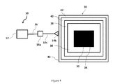
- FIG. 4 shows a schematic view of a monitoring system used to evaluate and monitor the status of a furnace using a probe.
- FIG. 5 shows a schematic view of a representation on a display of a portion of a wall forming part of an outer surface of a furnace.
- FIG. 6 shows a configuration of a management software architecture in accordance with certain aspects of a configuration.
- FIG. 1 a schematic top view of the components of a monitoring system 10 , used for a typical application of evaluating and monitoring or inspecting a unit under test (UUT) 18 , is shown in FIG. 1 .
- Monitoring system 10 comprises a control unit 12 , a sensor head 14 , and a set of cables 16 to electrically connect or couple control unit 12 and sensor head 14 .
- Sensor head 14 is capable of transmitting one or more electromagnetic (EM) waves into a region around sensor head 14 as well as receiving the corresponding one or more EM waves from that region within a frequency range, preferably in a frequency band of 0.25 GHz to 30 GHz.
- EM electromagnetic
- sensor head 14 may transmit a plurality of EM waves in the frequency domain, such that the time domain representation of this plurality of EM waves corresponds to a radiofrequency (RF) signal of short duration, for example a Gaussian, Rayleigh, Hermitian, or Laplacian pulse or of the like or a combination thereof.
- RF radiofrequency
- sensor head 14 may generate such type of pulse.
- the duration of the RF signal is preferably not larger than 5 nanoseconds.
- sensor head 14 comprises an RF module, and more particularly an RF transceiver, preferably consisting of an RF transmitter and an RF receiver, and one or more antennas or probes. While an exemplary antenna configuration is described herein in accordance with a particularly preferred embodiment, a number of antenna configurations may be suitable for use with the sensor head 14 described herein, and more particularly those antenna configurations set forth in U.S. Pat. No. 9,255,794 of Walton et al., and in U.S. Patent Application Publication No. US 2015/0276577 of Ruege et al., the specifications of which are incorporated herein by reference in their entireties.
- sensor head 14 apart from frequency domain or time domain RF-based approaches, may also use other technologies such as ultrasound, acoustic, eddy current, gamma rays and similar technologies.
- sensor head 14 comprises a computer-based processor with an executable computer code or software, capable of measuring and collecting data from the EM waves or RF signals received by sensor head 14 , and a data storage unit to store information pertinent to the data collected.
- set of cables 16 comprises one or a combination of more than one of the following: control cables to activate or deactivate sensor head 14 , data communication cables for data transfer between control unit 12 and sensor head 14 , and power cables to transfer power between control unit 12 and sensor head 14 . This allows transmission of both raw data and processed data from sensor head 14 to control unit 12 .
- a switch or trigger may be installed along one or more lines of set of cables 16 to enable an in-line trigger that allows partial or total activation or deactivation of the functionality of sensor head 14 .
- Set of cables 16 may also include navigation buttons to assist the operator in tracking the location on UUT 18 to be inspected and communicating with control unit 12 .
- Control unit 12 comprises a computer-based processor, having executable computer code or software thereon, to control sensor head 14 and to manage the communications and data transfer between control unit 12 and sensor head 14 through set of cables 16 .
- control unit 12 further comprises a storage unit to be able to store data and facilitate the processing of the data collected by sensor head 14 , and a display unit for displaying information.
- control unit 12 is a portable device.
- control unit 12 comprises a handheld or wearable electronic device capable of storing and processing data as well as displaying information to a user, including the identification and location of the asset being evaluated, confirmation of the areas already inspected, and the sections pending for inspection.
- control unit 12 and sensor head 14 may be realized through a wireless communication channel via Bluetooth, Wi-Fi, or equivalent methods.
- a status of UUT 18 may be determined by processing the collected data using the computer-based processor of control unit 12 .
- components of sensor head 14 and the computer-based processors of control unit 12 have not been shown as these components are not critical to the explanation of this configuration.
- FIG. 2 shows a schematic top view of monitoring system 10 in accordance with certain aspects of another configuration, wherein a computer-based processor 20 , having executable computer code or software thereon, is used to process the data collected by sensor head 14 .
- the data processed by computer-based processor 20 may be visually shown in a display 22 , which is connected to computer-based processor 20 through cable 24 .
- Computer-based processor 20 , display 22 , and cable 24 are commonly used devices that are well known in the prior art.
- sensor head 14 transfers the data associated with UUT 18 , through set of cables 16 , to control unit 12 , which communicates with computer-based processor 20 .
- control unit 12 which communicates with computer-based processor 20 .
- computer-based processor 20 Those skilled in the art will realize that various methods exist to transfer the data collected by sensor head 14 to computer-based processor 20 for further processing and displaying, including a portable memory device that stores such data, a wired cable connecting control unit 12 or sensor head 14 to computer-based processor 20 , and a wireless communication channel between control unit 12 or sensor head 14 and computer-based processor 20 .
- FIG. 3 shows a particular configuration of monitoring system 10 in which UUT 18 consists of a furnace 30 , comprising a chamber 32 enclosing a molten material 34 , and a first layer 36 , a second layer 38 , a third layer 40 , and a fourth layer 42 , wherein each of these layers is made of refractory or insulating materials.
- Furnace 30 is representative of applications used in the glass, steel, and plastic industries. In these applications, chamber 32 is typically surrounded by multiple layers of material to prevent heat loss and leakage of molten material to the outside of furnace 30 and as a safety measure to workers and equipment operating in the surroundings of furnace 30 .
- Each of layers 36 , 38 , 40 , and 42 has an outer surface and an inner surface opposite the outer surface, such that the inner surface is closer to chamber 32 .
- the inner surface of first layer 36 of refractory material is contiguous to (i.e., in physical contact with) chamber 32 .
- the inner walls of chamber 32 will degrade.
- the effects of this degradation include inner surface erosion, stress cracks, and refractory material diffusion into the molten material.
- molten material 34 such as molten glass, at high temperatures erodes and degrades the inner walls of chamber 32 and surrounding layers 36 , 38 , 40 , and 42 , creating a high risk of molten material leakage to the outside of furnace 30 .
- Typical thickness values of refractory and insulation material of furnace walls range from 1 inch to 24 inches on the sidewalls.
- monitoring a certain status of furnace 30 depends on the specific sensor head 14 , disposed in the vicinity of outer surface 43 of furnace 30 , used to collect data and connect to control unit 12 through set of cables 16 .
- the use of a refractory thickness sensor as sensor head 14 enables monitoring system 10 to determine the thickness and thickness profile of one or more of layers 36 , 38 , 40 , and 42 of furnace 30 .
- the use of a furnace tomography sensor as sensor head 14 enables monitoring system 10 to determine a thickness profile and assess the degree of penetration of molten material 34 into one or more of layers 36 , 38 , 40 , and 42 of furnace 30 .
- a plurality of sensors of the same type in either a monostatic or multistatic configuration, and other types of sensors may be used as sensor heads, including thermal imaging, temperature, and furnace bottom detection sensors.
- FIG. 4 shows an alternative configuration of monitoring system 10 , wherein sensor head 14 comprises three components: namely, an electronic device 14 a comprising an RF transceiver, a computer-based processor with executable computer code or software thereon, and a data storage unit; an antenna or probe 14 b ; and a cable 14 c , such as a coaxial cable, to electrically connect device 14 a to probe 14 b .
- This configuration allows setting up a unit of smaller size in the vicinity of outer surface 43 of furnace 30 , because probe 14 b is separated from electronic device 14 a.
- one or more probes 14 b may be permanently or temporarily installed in-situ over a plurality of locations of furnace 30 , especially in areas of difficult access.
- in-situ probes 14 b are installed in the vicinity of outer surface 43 of furnace 30 .
- device 14 a may connect to each probe 14 b through connectorized cable 14 c to collect the data corresponding to the area wherein each probe 14 b is installed.
- Probe 14 b need not be in physical contact with furnace 30 and can be mechanically actuated by a switch or trigger button located on control unit 12 or set of cables 16 .
- probe 14 b can be quickly activated by attaching a quick-connect cable 14 c .
- a plurality of sensors with communication capabilities may be installed in each of layers 36 , 38 , 40 , and 42 or chamber 32 , enclosing molten material 34 , to provide data to probe 14 b .
- this plurality of sensors is installed during furnace construction or during a repair process.
- a mechanical attachment such as a pole, using a quick-connect system to easily connect to probe 14 b may be used to prioritize usability of monitoring system 10 , to increase the accessibility of probe 14 b , and to extend the locations of furnace 30 that may be reachable by probe 14 b .
- the mechanical attachment is extendable and flexible, such as a gooseneck type for accessing tight spots, and provides certain self-alignment with a wall of furnace 30 .
- the mechanical attachment is also rugged, light weight, and collapsible to fit into a carry-on sized case.
- mechanical attachments may include telescopic poles, foldable elements, angled-section arms, and retractable parts.
- control unit 12 is capable of controlling and handling a plurality of sensor heads 14 and probes 14 b .
- the computer-based processor and the executable software of control unit 12 may enable the identification of the type of sensor head 14 connected to control unit 12 or the type of probe 14 b attached to device 14 a , by initiating a handshaking protocol between control unit 12 and sensor head 14 or device 14 a .
- This handshaking protocol is similar to the one used by a computer to recognize a flash drive. Accordingly, once the type of sensor head 14 or probe 14 b is identified, control unit 12 operates sensor head 14 or device 14 a for monitoring the corresponding status of furnace 30 .
- control unit 12 is capable of connecting to a variety of sensor heads 14 and probes 14 b .
- sensor heads 14 and probes 14 b Those skilled in the art will realize that a number of other types of sensors may be connected to control unit 12 , including temperature sensors to determine temperature profiles and furnace bottom sensors to determine the distance between the bottom of chamber 32 and outer surface 43 of furnace 30 in the area substantially parallel to the floor wherein furnace 30 is installed.
- FIG. 5 shows a schematic side view of a representation on a display of a portion of a wall 50 , which is part of outer surface 43 of a furnace.
- Wall 50 comprises a plurality of bricks 52 made of refractory material.
- a grid consisting of a first set of mapping labels 54 , vertically oriented, and a second set of mapping labels 56 , horizontally oriented, may be externally placed on outer surface 43 , to facilitate the tracking of the specific regions of the furnace being monitored in real time or over a certain period of time.
- outer surface 43 is labeled with letters or numbers in rows and columns using labels 54 , 56 . Labels 54 , 56 should be capable of withstanding the relatively high temperatures, which may reach over 1000° F., on outer surface 43 .
- customized software is installed in control unit 12 to enable the mapping of outer surface 43 of furnace 30 , based on mapping labels 54 , 56 .
- the dimensions and layout of furnace 30 including each of layers 36 , 38 , 40 , and 42 , type of material, and layer thickness are setup in the customized software installed in control unit 12 .
- the rows and columns as mapped on outer surface 43 of furnace 30 , according to labels 54 , 56 are correspondingly mapped onto a software layout of furnace 30 and installed in control unit 12 to enable proper mapping and tracking of each inspection of a region of furnace 30 .
- an asset life optimization system comprises a monitoring system integrated with a management software subsystem. More specifically, in a preferred configuration, each of the above-described configurations, in reference to FIGS. 1 to 4 , may be integrated with a management software subsystem to implement an asset life optimization system, wherein furnace 30 represents such asset.
- the management software subsystem may be used to perform and control the monitoring, recording, mapping, visualization, diagnosing, analysis, and tracking of the status of furnace 30 .
- FIG. 6 shows a configuration of a management software subsystem architecture 60 , comprising a first software module 62 installed in control unit 12 , a cloud computer subsystem 64 , and a second software module 66 installed in a client computer 68 .
- Management software subsystem architecture 60 enables the data collection and storage by control unit 12 , the data transfer and processing, and the inspection reports generation.
- a map of the design of furnace 30 is downloaded to control unit 12 .
- a user may operate software module 62 to enter on control unit 12 the specific region of furnace 30 to be inspected. This may be done by selecting on control unit 12 the corresponding block or section, according to the identification of rows and columns on outer surface 43 of furnace 30 , in reference to mapping labels 54 , 56 .
- software module 62 enables one or more navigation buttons on control unit 12 to allow a user to select a region of furnace 30 to be inspected, or to control a function, such as triggering the collection of data, of sensor head 14 or device 14 a .
- software module 62 stores on control unit 12 all the data collected for each inspected section of outer surface 43 of furnace 30 .
- the map of the design of furnace 30 is uploaded to cloud computer subsystem 64 , and second software module 66 allows downloading this map from cloud computer subsystem 64 to control unit 12 .
- software module 62 may be enabled to download this map directly from cloud computer subsystem 64 .
- software module 62 may be used to transfer the data, corresponding to the inspected block or section of furnace 30 , from control unit 12 to cloud computer subsystem 64 .
- second software module 66 may be used to download the data from cloud computer subsystem 64 into client computer 68 .
- a user may operate second software module 66 to enable the transfer of data from control unit 12 to cloud computer subsystem 64 .
- second software module 66 may be used for evaluation and analysis of the data stored in either cloud computer subsystem 64 or client computer 68 . This data analysis may include the use of data processing and image processing algorithms and signal processing visualization techniques.
- an inspection report may include a two-dimensional or a three-dimensional visualization providing information of the outer walls of furnace 30 .
- a report may indicate the thickness of the refractory material, with mapping labels 54 , 56 or color-coded representation, corresponding to regions where the thickness may have reached certain levels, according to a predefined criteria.
- an inspection report may include a two-dimensional visualization of outer surface 43 of furnace 30 , similar to the representation shown in FIG. 5 , displaying color-coded or warning information, corresponding to a flaw or the thickness of the refractory material and according to predetermined thickness levels (e.g., normal, moderate, or critical) for each area of outer surface 43 that have been inspected.
- an inspection report may include a three-dimensional visualization of a cross-sectional view of wall 50 showing the status of each of layers 36 , 38 , 40 , and 42 of furnace 30 .
- inspection reports may provide information in terms of a thickness profile over time for a specific block or section of furnace 30 to observe the trend of the material degradation and estimate appropriate times for repairs or furnace utilization.
- Other inspection reports may include the level of penetration of molten material 34 into each of layers 36 , 38 , 40 , and 42 of furnace 30 and temperature corresponding to a specific block or section of furnace 30 to identify areas of potential breakage and prevent damage to furnace 30 and the surrounding equipment and personnel.
- Software module 66 is able to keep record of each inspection, compute refractory material erosion rate, provide a history of the degradation of each of layers 36 , 38 , 40 , and 42 of furnace 30 , determine the impact of the melting process, and evaluate the performance of each of layers 36 , 38 , 40 , and 42 of furnace 30 for specific types of molten material used.
- client computer 68 may be directly connected to control unit 12 .
- client computer 68 in FIG. 6 may be used as computer-based processor 20 in FIG. 2 .
- all data collection, storing, transferring, processing, and reporting may be performed locally.
- client computer 68 may be connected to or integrated with an external computer or server having a secure database and a backup storage system.
- This external computer or server may replace cloud computer subsystem 64 .
- this external computer or server comprises a web application such that a user can remotely access and visualize the results of a furnace inspection through a web or smartphone platform.
- data processing and image processing algorithms may be implemented by using one or a combination of more than one technique.
- These techniques may include Fourier transform, spectral analysis, frequency- and time-domain response analyses, digital filtering, convolution and correlation, decimation and interpolation, adaptive signal processing, waveform analysis, and data windows and phase unwrapping for data processing; and time domain, back projection, delay and sum, synthetic aperture radar imaging, back propagation, inverse scattering, and super-resolution, either with or without the application of differential imaging, for image processing.
Landscapes
- Physics & Mathematics (AREA)
- Engineering & Computer Science (AREA)
- Electromagnetism (AREA)
- General Physics & Mathematics (AREA)
- Chemical & Material Sciences (AREA)
- General Engineering & Computer Science (AREA)
- Health & Medical Sciences (AREA)
- Life Sciences & Earth Sciences (AREA)
- Mechanical Engineering (AREA)
- Analytical Chemistry (AREA)
- Biochemistry (AREA)
- General Health & Medical Sciences (AREA)
- Immunology (AREA)
- Pathology (AREA)
- Waste-Gas Treatment And Other Accessory Devices For Furnaces (AREA)
- Length-Measuring Devices Using Wave Or Particle Radiation (AREA)
Priority Applications (1)
| Application Number | Priority Date | Filing Date | Title |
|---|---|---|---|
| US15/337,851 US10054367B2 (en) | 2015-10-29 | 2016-10-28 | Asset life optimization and monitoring system |
Applications Claiming Priority (2)
| Application Number | Priority Date | Filing Date | Title |
|---|---|---|---|
| US201562247869P | 2015-10-29 | 2015-10-29 | |
| US15/337,851 US10054367B2 (en) | 2015-10-29 | 2016-10-28 | Asset life optimization and monitoring system |
Publications (2)
| Publication Number | Publication Date |
|---|---|
| US20170131033A1 US20170131033A1 (en) | 2017-05-11 |
| US10054367B2 true US10054367B2 (en) | 2018-08-21 |
Family
ID=58631210
Family Applications (1)
| Application Number | Title | Priority Date | Filing Date |
|---|---|---|---|
| US15/337,851 Active US10054367B2 (en) | 2015-10-29 | 2016-10-28 | Asset life optimization and monitoring system |
Country Status (5)
| Country | Link |
|---|---|
| US (1) | US10054367B2 (de) |
| EP (1) | EP3368910B1 (de) |
| JP (1) | JP6644137B2 (de) |
| CA (1) | CA2998778C (de) |
| WO (1) | WO2017075453A1 (de) |
Cited By (5)
| Publication number | Priority date | Publication date | Assignee | Title |
|---|---|---|---|---|
| US11237124B2 (en) | 2019-09-26 | 2022-02-01 | Harbisonwalker International, Inc. | Predictive refractory performance measurement system |
| US20230152243A1 (en) * | 2020-04-06 | 2023-05-18 | Paneratech, Inc. | Method and apparatus for evaluation of a status of a material in metallurgical vessels |
| US12085384B2 (en) | 2020-12-17 | 2024-09-10 | Paneratech, Inc. | System and method for evaluating a status of a material in metallurgical vessels |
| US12276620B2 (en) | 2020-06-30 | 2025-04-15 | Paneratech, Inc. | Antenna-grating coupled sensing system for clutter reduction during evaluation of a status of a material |
| US12523427B2 (en) * | 2020-09-10 | 2026-01-13 | L'air Liquide, Societe Anonyme Pour L'etude Et L'exploitation Des Procedes Georges Claude | System and method for monitoring and controlling furnaces |
Families Citing this family (5)
| Publication number | Priority date | Publication date | Assignee | Title |
|---|---|---|---|---|
| JP2017182536A (ja) * | 2016-03-31 | 2017-10-05 | アズビル株式会社 | 高温炉設備の保全管理装置および方法 |
| JP7189426B2 (ja) * | 2018-12-05 | 2022-12-14 | 日本電信電話株式会社 | 表面変化検出体及びそれを用いた表面変化検出方法 |
| CN111965225B (zh) * | 2020-07-17 | 2023-09-22 | 沈阳广泰真空科技股份有限公司 | 一种真空感应熔炼炉中的坩埚监测方法及装置 |
| CA3197416C (en) * | 2020-11-04 | 2023-08-01 | Tomas Richter | Predictive refractory performance measurement system |
| WO2024158427A1 (en) * | 2023-01-24 | 2024-08-02 | Paneratech, Inc. | Refractory monitoring system for high-voltage and high-temperature environment applications |
Citations (14)
| Publication number | Priority date | Publication date | Assignee | Title |
|---|---|---|---|---|
| US5521697A (en) * | 1995-01-25 | 1996-05-28 | Houston Industries Incorporated | Protective cover for fiberoptic scanner head |
| US6198293B1 (en) | 1998-03-26 | 2001-03-06 | Massachusetts Institute Of Technology | Method and apparatus for thickness measurement using microwaves |
| US20040034442A1 (en) * | 2002-08-16 | 2004-02-19 | General Electric Company | Furnace pacing for multistrand mill |
| US20070260378A1 (en) | 2005-12-05 | 2007-11-08 | Clodfelter James F | Apparatus for detecting subsurface objects with a reach-in arm |
| US20090068062A1 (en) * | 2003-07-18 | 2009-03-12 | Bio-Rad Laboratories, Inc. | System and method for multi-analyte detection |
| US20100123467A1 (en) | 2008-11-17 | 2010-05-20 | General Electric Company | System and method for measuring thickness of a refractory wall of a gasifier using electromagnetic energy |
| US20130120738A1 (en) | 2011-11-15 | 2013-05-16 | Process Metrix | Apparatus, Process, and System for Monitoring the Integrity of Containers |
| US20130144554A1 (en) * | 2011-12-06 | 2013-06-06 | Paneratech, Inc. | Microwave probe for furnace refractory material |
| US20130245965A1 (en) * | 2011-03-25 | 2013-09-19 | Michael John Kane | Handheld HVAC/R Test and Measurement Instrument |
| US20140340279A1 (en) | 2013-05-14 | 2014-11-20 | Paneratech, Inc. | Adaptive antenna feeding and method for optimizing the design thereof |
| US20150109618A1 (en) * | 2012-04-19 | 2015-04-23 | Zolo Technologies, Inc. | In-Furnace Retro-Reflectors with Steerable Tunable Diode Laser Absorption Spectrometer |
| US20150276577A1 (en) | 2014-03-26 | 2015-10-01 | Paneratech, Inc. | Material erosion monitoring system and method |
| US20150362439A1 (en) | 2014-06-11 | 2015-12-17 | Paneratech, Inc. | Device and method for evaluation of a material |
| US9391360B1 (en) | 2013-04-16 | 2016-07-12 | Paneratech, Inc. | Antenna and method for optimizing the design thereof |
Family Cites Families (6)
| Publication number | Priority date | Publication date | Assignee | Title |
|---|---|---|---|---|
| JP2006153845A (ja) * | 2004-11-02 | 2006-06-15 | Nippon Steel Corp | 耐火物厚み測定方法及び耐火物厚み測定装置 |
| US7976770B1 (en) | 2005-07-29 | 2011-07-12 | Hatch Ltd. | Diagnostic system and method for metallurgical reactor cooling elements |
| ITMI20060084A1 (it) | 2006-01-19 | 2007-07-20 | Giuseppe Cristini S P A Sa | Metodo e dispositivo per misurare lo spessore di uno strato di materiale |
| ES2482093T3 (es) | 2007-09-28 | 2014-08-01 | Hatch Ltd. | Método para el control acústico de bloques de colada y elementos similares |
| JP6244093B2 (ja) * | 2013-03-15 | 2017-12-06 | 安立計器株式会社 | 磁石固定式温度計 |
| JP2015141140A (ja) * | 2014-01-29 | 2015-08-03 | 株式会社ミツトヨ | 遠隔操作可能な測定機及び測定システム |
-
2016
- 2016-10-28 EP EP16860942.8A patent/EP3368910B1/de active Active
- 2016-10-28 WO PCT/US2016/059469 patent/WO2017075453A1/en not_active Ceased
- 2016-10-28 JP JP2018519748A patent/JP6644137B2/ja active Active
- 2016-10-28 US US15/337,851 patent/US10054367B2/en active Active
- 2016-10-28 CA CA2998778A patent/CA2998778C/en active Active
Patent Citations (15)
| Publication number | Priority date | Publication date | Assignee | Title |
|---|---|---|---|---|
| US5521697A (en) * | 1995-01-25 | 1996-05-28 | Houston Industries Incorporated | Protective cover for fiberoptic scanner head |
| US6198293B1 (en) | 1998-03-26 | 2001-03-06 | Massachusetts Institute Of Technology | Method and apparatus for thickness measurement using microwaves |
| US20040034442A1 (en) * | 2002-08-16 | 2004-02-19 | General Electric Company | Furnace pacing for multistrand mill |
| US20090068062A1 (en) * | 2003-07-18 | 2009-03-12 | Bio-Rad Laboratories, Inc. | System and method for multi-analyte detection |
| US20070260378A1 (en) | 2005-12-05 | 2007-11-08 | Clodfelter James F | Apparatus for detecting subsurface objects with a reach-in arm |
| US20100123467A1 (en) | 2008-11-17 | 2010-05-20 | General Electric Company | System and method for measuring thickness of a refractory wall of a gasifier using electromagnetic energy |
| US20130245965A1 (en) * | 2011-03-25 | 2013-09-19 | Michael John Kane | Handheld HVAC/R Test and Measurement Instrument |
| US20130120738A1 (en) | 2011-11-15 | 2013-05-16 | Process Metrix | Apparatus, Process, and System for Monitoring the Integrity of Containers |
| US20130144554A1 (en) * | 2011-12-06 | 2013-06-06 | Paneratech, Inc. | Microwave probe for furnace refractory material |
| US9255794B2 (en) | 2011-12-06 | 2016-02-09 | Paneratech, Inc. | Microwave probe for furnace refractory material |
| US20150109618A1 (en) * | 2012-04-19 | 2015-04-23 | Zolo Technologies, Inc. | In-Furnace Retro-Reflectors with Steerable Tunable Diode Laser Absorption Spectrometer |
| US9391360B1 (en) | 2013-04-16 | 2016-07-12 | Paneratech, Inc. | Antenna and method for optimizing the design thereof |
| US20140340279A1 (en) | 2013-05-14 | 2014-11-20 | Paneratech, Inc. | Adaptive antenna feeding and method for optimizing the design thereof |
| US20150276577A1 (en) | 2014-03-26 | 2015-10-01 | Paneratech, Inc. | Material erosion monitoring system and method |
| US20150362439A1 (en) | 2014-06-11 | 2015-12-17 | Paneratech, Inc. | Device and method for evaluation of a material |
Non-Patent Citations (1)
| Title |
|---|
| International Search Report issued in copending International Patent Application No. PCT/US16/59469 dated Jan. 31, 2017. |
Cited By (7)
| Publication number | Priority date | Publication date | Assignee | Title |
|---|---|---|---|---|
| US11237124B2 (en) | 2019-09-26 | 2022-02-01 | Harbisonwalker International, Inc. | Predictive refractory performance measurement system |
| US11579104B2 (en) | 2019-09-26 | 2023-02-14 | Harbisonwalker International, Inc. | Predictive refractory performance measurement system |
| US20230152243A1 (en) * | 2020-04-06 | 2023-05-18 | Paneratech, Inc. | Method and apparatus for evaluation of a status of a material in metallurgical vessels |
| US12061155B2 (en) * | 2020-04-06 | 2024-08-13 | Paneratech, Inc. | Method and apparatus for evaluation of a status of a material in metallurgical vessels |
| US12276620B2 (en) | 2020-06-30 | 2025-04-15 | Paneratech, Inc. | Antenna-grating coupled sensing system for clutter reduction during evaluation of a status of a material |
| US12523427B2 (en) * | 2020-09-10 | 2026-01-13 | L'air Liquide, Societe Anonyme Pour L'etude Et L'exploitation Des Procedes Georges Claude | System and method for monitoring and controlling furnaces |
| US12085384B2 (en) | 2020-12-17 | 2024-09-10 | Paneratech, Inc. | System and method for evaluating a status of a material in metallurgical vessels |
Also Published As
| Publication number | Publication date |
|---|---|
| JP2018535408A (ja) | 2018-11-29 |
| WO2017075453A1 (en) | 2017-05-04 |
| CA2998778C (en) | 2024-02-27 |
| EP3368910A1 (de) | 2018-09-05 |
| CA2998778A1 (en) | 2017-05-04 |
| EP3368910A4 (de) | 2019-06-05 |
| US20170131033A1 (en) | 2017-05-11 |
| EP3368910B1 (de) | 2025-08-20 |
| EP3368910C0 (de) | 2025-08-20 |
| JP6644137B2 (ja) | 2020-02-12 |
Similar Documents
| Publication | Publication Date | Title |
|---|---|---|
| US10054367B2 (en) | Asset life optimization and monitoring system | |
| US10620115B2 (en) | Microwave horn antennas-based transducer system for CUI inspection without removing the insulation | |
| US9255794B2 (en) | Microwave probe for furnace refractory material | |
| JP6633549B2 (ja) | 材料の評価のためのデバイス及び方法 | |
| US10908130B2 (en) | Asset integrity monitoring using cellular networks | |
| US12061155B2 (en) | Method and apparatus for evaluation of a status of a material in metallurgical vessels | |
| US12276620B2 (en) | Antenna-grating coupled sensing system for clutter reduction during evaluation of a status of a material | |
| EP4655544A1 (de) | Feuerfestes überwachungssystem für hochspannungs- und hochtemperaturumgebungsanwendungen | |
| CA2950181C (en) | Device and method for evaluation of a material | |
| KR20120069089A (ko) | Tdr계측기를 이용한 사면거동 계측장치 | |
| EP3155363B1 (de) | Vorrichtung und verfahren zur beurteilung eines materials |
Legal Events
| Date | Code | Title | Description |
|---|---|---|---|
| AS | Assignment |
Owner name: PANERATECH, INC., VIRGINIA Free format text: ASSIGNMENT OF ASSIGNORS INTEREST;ASSIGNORS:BAYRAM, YAKUP;RUEGE, ALEXANDER;KNOWLES, JUSTIN;SIGNING DATES FROM 20161115 TO 20161129;REEL/FRAME:044687/0601 |
|
| STCF | Information on status: patent grant |
Free format text: PATENTED CASE |
|
| MAFP | Maintenance fee payment |
Free format text: PAYMENT OF MAINTENANCE FEE, 4TH YR, SMALL ENTITY (ORIGINAL EVENT CODE: M2551); ENTITY STATUS OF PATENT OWNER: SMALL ENTITY Year of fee payment: 4 |
|
| MAFP | Maintenance fee payment |
Free format text: PAYMENT OF MAINTENANCE FEE, 8TH YR, SMALL ENTITY (ORIGINAL EVENT CODE: M2552); ENTITY STATUS OF PATENT OWNER: SMALL ENTITY Year of fee payment: 8 |