US10047953B2 - Gasification melting facility - Google Patents
Gasification melting facility Download PDFInfo
- Publication number
- US10047953B2 US10047953B2 US14/000,315 US201114000315A US10047953B2 US 10047953 B2 US10047953 B2 US 10047953B2 US 201114000315 A US201114000315 A US 201114000315A US 10047953 B2 US10047953 B2 US 10047953B2
- Authority
- US
- United States
- Prior art keywords
- incombustibles
- pyrolysis gas
- pulverized
- airflow
- furnace
- Prior art date
- Legal status (The legal status is an assumption and is not a legal conclusion. Google has not performed a legal analysis and makes no representation as to the accuracy of the status listed.)
- Active, expires
Links
Images


Classifications
-
- F—MECHANICAL ENGINEERING; LIGHTING; HEATING; WEAPONS; BLASTING
- F23—COMBUSTION APPARATUS; COMBUSTION PROCESSES
- F23G—CREMATION FURNACES; CONSUMING WASTE PRODUCTS BY COMBUSTION
- F23G5/00—Incineration of waste; Incinerator constructions; Details, accessories or control therefor
- F23G5/02—Incineration of waste; Incinerator constructions; Details, accessories or control therefor with pretreatment
- F23G5/027—Incineration of waste; Incinerator constructions; Details, accessories or control therefor with pretreatment pyrolising or gasifying stage
-
- F—MECHANICAL ENGINEERING; LIGHTING; HEATING; WEAPONS; BLASTING
- F23—COMBUSTION APPARATUS; COMBUSTION PROCESSES
- F23G—CREMATION FURNACES; CONSUMING WASTE PRODUCTS BY COMBUSTION
- F23G5/00—Incineration of waste; Incinerator constructions; Details, accessories or control therefor
- F23G5/02—Incineration of waste; Incinerator constructions; Details, accessories or control therefor with pretreatment
- F23G5/033—Incineration of waste; Incinerator constructions; Details, accessories or control therefor with pretreatment comminuting or crushing
-
- F—MECHANICAL ENGINEERING; LIGHTING; HEATING; WEAPONS; BLASTING
- F23—COMBUSTION APPARATUS; COMBUSTION PROCESSES
- F23G—CREMATION FURNACES; CONSUMING WASTE PRODUCTS BY COMBUSTION
- F23G5/00—Incineration of waste; Incinerator constructions; Details, accessories or control therefor
- F23G5/30—Incineration of waste; Incinerator constructions; Details, accessories or control therefor having a fluidised bed
-
- F—MECHANICAL ENGINEERING; LIGHTING; HEATING; WEAPONS; BLASTING
- F23—COMBUSTION APPARATUS; COMBUSTION PROCESSES
- F23G—CREMATION FURNACES; CONSUMING WASTE PRODUCTS BY COMBUSTION
- F23G5/00—Incineration of waste; Incinerator constructions; Details, accessories or control therefor
- F23G5/32—Incineration of waste; Incinerator constructions; Details, accessories or control therefor the waste being subjected to a whirling movement, e.g. cyclonic incinerators
-
- F—MECHANICAL ENGINEERING; LIGHTING; HEATING; WEAPONS; BLASTING
- F23—COMBUSTION APPARATUS; COMBUSTION PROCESSES
- F23G—CREMATION FURNACES; CONSUMING WASTE PRODUCTS BY COMBUSTION
- F23G2201/00—Pretreatment
- F23G2201/30—Pyrolysing
- F23G2201/303—Burning pyrogases
-
- F—MECHANICAL ENGINEERING; LIGHTING; HEATING; WEAPONS; BLASTING
- F23—COMBUSTION APPARATUS; COMBUSTION PROCESSES
- F23G—CREMATION FURNACES; CONSUMING WASTE PRODUCTS BY COMBUSTION
- F23G2201/00—Pretreatment
- F23G2201/30—Pyrolysing
- F23G2201/304—Burning pyrosolids
-
- F—MECHANICAL ENGINEERING; LIGHTING; HEATING; WEAPONS; BLASTING
- F23—COMBUSTION APPARATUS; COMBUSTION PROCESSES
- F23G—CREMATION FURNACES; CONSUMING WASTE PRODUCTS BY COMBUSTION
- F23G2201/00—Pretreatment
- F23G2201/40—Gasification
-
- F—MECHANICAL ENGINEERING; LIGHTING; HEATING; WEAPONS; BLASTING
- F23—COMBUSTION APPARATUS; COMBUSTION PROCESSES
- F23G—CREMATION FURNACES; CONSUMING WASTE PRODUCTS BY COMBUSTION
- F23G2202/00—Combustion
- F23G2202/20—Combustion to temperatures melting waste
-
- F—MECHANICAL ENGINEERING; LIGHTING; HEATING; WEAPONS; BLASTING
- F23—COMBUSTION APPARATUS; COMBUSTION PROCESSES
- F23J—REMOVAL OR TREATMENT OF COMBUSTION PRODUCTS OR COMBUSTION RESIDUES; FLUES
- F23J2900/00—Special arrangements for conducting or purifying combustion fumes; Treatment of fumes or ashes
- F23J2900/01001—Sorting and classifying ashes or fly-ashes from the combustion chamber before further treatment
Definitions
- the present invention relates to a gasification melting facility that gasifies and melts waste.
- the gasification and ash melting system includes: a gasification furnace that gasifies waste by thermally decomposing the waste; a melting furnace that is provided on the downstream side of the gasification furnace, combusts pyrolysis gas generated by the gasification furnace at high temperature, and converts ashes contained in the gas into molten slag; and a secondary combustion chamber that combusts flue gas discharged from the melting furnace.
- the gasification and ash melting system extracts slag from the melting furnace to reuse the slag as materials of construction such as base course materials or recovers waste heat from flue gas discharged from the secondary combustion chamber to generate electricity.
- a fluidized bed gasification furnace is widely used as the gasification furnace of such a gasification and ash melting system.
- a fluidized bed in which a fluid medium is fluidized by the supply of combustion air, is formed at the bottom of the fluidized bed gasification furnace, and the fluidized bed gasification furnace is a device that partially combusts the waste put in the fluidized bed and thermally decomposes the waste in the fluidized bed maintained at high temperature by the combustion heat.
- the fluidized bed gasification furnace is configured to discharge incombustibles from the bottom of the gasification furnace together with sand that is a fluid medium. Since the gasification melting facility requires volume reduction as described above, it is important to reduce the volume of incombustibles to be ultimately buried and treated. Means for reducing the volume of incombustibles, which are to be finally buried and treated, by recovering valuable metal, such as iron or aluminum, from incombustibles, and the like are known as means for reducing the volume of incombustibles.
- a gasification melting facility that pulverizes incombustibles from which valuable metal has been removed and introduces the pulverized incombustibles into a melting furnace to melt the pulverized incombustibles is disclosed in Patent Document 1 as means for reducing the volume of other wastes.
- This gasification melting facility can introduce the incombustibles into the melting furnace by pulverizing the incombustibles after further removing metals (metals other than valuable metal) from the incombustibles, from which valuable metal has been removed, using a vibrating screen and by cutting out a fixed amount of the pulverized incombustibles.
- Patent Document 1 Japanese Unexamined Patent Application, First Publication No. 2008-69984
- the invention has been made in consideration of these circumstances and an object of the present invention is to provide a gasification melting facility that can be constructed at lower cost by the reduction of the number of devices forming the facility and can reliably remove metals.
- the present invention employs the following means.
- a gasification melting facility includes: a fluidized bed gasification furnace that generates pyrolysis gas by thermally decomposing waste and discharges incombustibles; a vertical cyclone melting furnace that includes a pyrolysis gas duct through which the pyrolysis gas is introduced; a pyrolysis gas passage that connects the fluidized bed gasification furnace with the pyrolysis gas duct of the vertical cyclone melting furnace; pulverizer that pulverize the incombustibles, which are discharged from the fluidized bed gasification furnace, into pulverized incombustibles so that the particle size of the incombustibles becomes fine; and airflow transporter that conveys the pulverized incombustibles, which are generated by the pulverizer, together with airflow, puts the pulverized incombustibles in the pyrolysis gas passage, and separates metal contained in the pulverized incombustibles by a difference in specific gravity while conveying the
- the pulverized incombustibles are conveyed together with airflow and metals contained in the pulverized incombustibles are separated while being conveyed together with airflow. Accordingly, a device that removes metal does not need to be provided, and therefore, it is possible to construct a gasification melting facility at lower cost.
- the particle size of the pulverized incombustibles be adjusted to a fine particle size smaller than 0.1 mm.
- the gasification melting facility preferably further includes, on a front stage of the pulverizer, classifier that classifies the incombustibles and a fluid medium that is discharged from the fluidized bed gasification furnace, separator that separates iron and aluminum from the incombustibles that are classified by the classifier, and fixed amount feeder that feeds the incombustibles, which have been subjected to the separation performed by the separator, to the pulverizer by a fixed amount.
- classifier that classifies the incombustibles and a fluid medium that is discharged from the fluidized bed gasification furnace
- separator that separates iron and aluminum from the incombustibles that are classified by the classifier
- fixed amount feeder that feeds the incombustibles, which have been subjected to the separation performed by the separator, to the pulverizer by a fixed amount.
- the present invention it is possible to separate valuable metal from the incombustibles and to adjust the amount of the incombustibles to be fed to the pulverizer.
- the pyrolysis gas duct be provided with a premix burner.
- the pyrolysis gas and the pulverized incombustibles pass through the premix burner and are fed to the vertical cyclone melting furnace, it is possible to sufficiently preheat the pyrolysis gas and the pulverized incombustibles. Accordingly, smooth melting can be performed.
- the gasification melting facility according to the present invention include a plurality of the pyrolysis gas passages and a plurality of the pyrolysis gas ducts.
- the pyrolysis gas and the pulverized incombustibles are blown into the vertical cyclone melting furnace to cause a swirling flow.
- the pyrolysis gas is introduced from the plurality of pyrolysis gas ducts, a swirling force of a gas flow in the vertical cyclone melting furnace can be increased and it is possible to prevent the pulverized incombustibles from carrying over in the flue gas without being caught in the vertical cyclone melting furnace.
- the airflow transporter preferably includes a pneumatic transport pipe that is curved toward the downstream side, a blower that generates airflow in the pneumatic transport pipe, and a metal removal pipe that extends downward from a curved portion of the pneumatic transport pipe.
- the pulverized incombustibles are conveyed together with airflow and metals contained in the pulverized incombustibles are separated while being conveyed together with airflow. Accordingly, a device that removes metal does not need to be provided, and therefore, it is possible to construct a gasification melting facility at lower cost.
- FIG. 1 is a view showing the structure of a gasification melting facility of an embodiment of the present invention.
- FIG. 2 is a schematic view of a pneumatic transport pipe of the embodiment of the present invention.
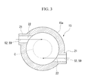
- FIG. 3 is a cross-sectional view taken along line A-A of FIG. 1 .
- a gasification melting facility 1 of this embodiment includes a fluidized bed gasification furnace 2 and a melting apparatus 4 .
- the gasification melting facility 1 introduces pyrolysis gas 52 , which is generated by the thermal decomposition of waste 51 in the fluidized bed gasification furnace 2 , to the melting apparatus 4 through a pyrolysis gas passage 3 .
- the fluidized bed gasification furnace 2 includes a gasification furnace body 5 having a rectangular cylindrical shape, and a waste inlet 6 including a waste discharge device 6 a is provided on one side wall of the gasification furnace body 5 . Further, a pyrolysis gas outlet 23 through which the pyrolysis gas generated in the gasification furnace is discharged is provided at the top portion of the gasification furnace body 5 , and an incombustible outlet 7 is provided at the lower portion of the gasification furnace body 5 . Furthermore, a fluid medium 8 (mainly, silica sand) is circulated and supplied to the bottom portion of the fluidized bed gasification furnace 2 .
- a fluid medium 8 mainly, silica sand
- Incombustibles and a fluid medium 53 which are discharged from the incombustible outlet 7 , are fed to a sand classifier 9 , and are separated into incombustibles 54 and a fluid medium 55 .
- the fluid medium 55 which is separated here, is returned to the fluidized bed gasification furnace 2 by means such as a sand circulating elevator.
- the incombustibles 54 which are discharged from the sand classifier 9 , are fed to a separation device (separator) that includes a magnetic separator 10 and an aluminum sorter 11 .
- a separation device that includes a magnetic separator 10 and an aluminum sorter 11 .
- the incombustibles 54 are fed to the magnetic separator 10 , and iron is then separated.
- incombustibles 56 which are discharged from the magnetic separator 10 , are fed to the aluminum sorter 11 , and aluminum is separated. Accordingly, valuable metal including iron and aluminum is separated.
- Incombustibles 57 which are discharged from the aluminum sorter 11 , are fed to a fixed amount feeding device 13 that includes a hopper 12 .
- a fixed amount of the incombustibles 57 which are stored in the hopper 12 , is cut out in the fixed amount feeding device 13 .
- the cut incombustibles 58 are fed to a powdering machine 14 and are pulverized to have a particle size of 0.1 mm or less, so that the particle size of the incombustibles 58 is adjusted.
- the incombustibles, which have been pulverized are referred to as pulverized incombustibles 59 .
- the particle size of the incombustibles 58 is adjusted to 0.1 mm or less, the incombustibles 58 are appropriately scattered by airflow when the pulverized incombustibles 59 are introduced into a pneumatic transport pipe 31 of an airflow conveyor 30 to be described below.
- the airflow conveyor 30 is provided below the powdering machine 14 .
- the airflow conveyor 30 includes a pneumatic transport pipe 31 on which a curved portion 35 is formed, a blower 32 that generates airflow in the pneumatic transport pipe 31 , and a metal removal pipe 33 that is provided on the curved portion 35 .
- the blower 32 is installed so as to generate airflow toward the downstream side from an upstream end of the pneumatic transport pipe 31 .
- an introduction portion 34 and the curved portion 35 are formed on the pneumatic transport pipe 31 in this order from the upstream side. Since the introduction portion 34 is connected to an outlet of the powdering machine 14 , the pulverized incombustibles 59 having been pulverized by the powdering machine 14 are introduced into the pneumatic transport pipe 31 from the introduction portion 34 .
- the pneumatic transport pipe 31 is curved on the downstream side of the introduction portion 34 , so that the curved portion 35 is formed.
- the pneumatic transport pipe 31 is curved upward at the curved portion 35 . Further, the metal removal pipe 33 extends downward from the curved portion 35 .
- the pneumatic transport pipe 31 is branched into two pipes on the downstream side of the curved portion 35 .
- the pneumatic transport pipe 31 which is branched into two pneumatic transport pipes, is connected to branched pyrolysis gas passage 3 to be described below.
- the melting apparatus 4 includes a vertical cyclone melting furnace 15 , a secondary combustion chamber 17 that is connected to an upper portion of the vertical cyclone melting furnace 15 through a connecting portion 16 , and a boiler portion 18 that is connected to a downstream portion of the secondary combustion chamber 17 .
- the vertical cyclone melting furnace 15 has a circular cross-section, and a flue gas outlet 19 having a throttling structure is formed at the upper portion of the vertical cyclone melting furnace 15 .
- the diameter of the vertical cyclone melting furnace 15 is reduced once at the flue gas outlet 19 , and the vertical cyclone melting furnace 15 extends upward in a conical shape so as to be widened and is connected to the secondary combustion chamber 17 .
- a slag outlet 20 is provided at the lower portion of the vertical cyclone melting furnace 15 .
- the vertical cyclone melting furnace 15 includes a substantially cylindrical furnace wall 15 a and a pair of pyrolysis gas ducts 21 through which the pyrolysis gas 52 is introduced are horizontally provided on the cross-section of the furnace wall 15 a at predetermined positions in the up and down direction.
- the pyrolysis gas ducts 21 are disposed so that the pyrolysis gas 52 introduced from the pyrolysis gas ducts 21 is ejected in the tangential direction of a circle C formed in the vertical cyclone melting furnace.
- premix burners 22 are installed at portions of the pyrolysis gas ducts 21 that are connected to the vertical cyclone melting furnace 15 .
- Combustion air is blown into the premix burners 22 from nozzle holes that are formed on the circumferential surfaces of the premix burners 22 .
- Air, oxygen, oxygen-enriched air, or the like may be used as the combustion air.
- an air ratio of the combustion air may be in the range of 0.9 to 1.1, and preferably about 1.0. It is possible to stably maintain the temperature in the furnace high by setting the air ratio as described above.
- the pyrolysis gas 52 and the combustion air are blown into the vertical cyclone melting furnace 15 after being mixed with each other in the premix burners 22 in advance in this way, the pyrolysis gas 52 and the combustion air are sufficiently mixed with each other. Accordingly, it is possible to instantly combust the pyrolysis gas 52 in the furnace.
- the secondary combustion chamber 17 is formed to have a square cross-section.
- the connecting portion 16 of which the diameter is reduced toward the flue gas outlet 19 of the vertical cyclone melting furnace 15 is provided at the lower end portion of the secondary combustion chamber 17 .
- the boiler portion 18 is provided on the flue gas-downstream side of the secondary combustion chamber 17 , heat is recovered by a superheater (not shown) or the like installed on a flue.
- Flue gas 62 which has passed through the boiler portion 18 , passes through a reaction dust collector, a catalytic reaction device, and the like, which are provided on the rear stage, and is discharged to the atmosphere through a chimney.
- the pyrolysis gas 52 is introduced into the vertical cyclone melting furnace 15 through the pyrolysis gas passage 3 .
- the pyrolysis gas outlet 23 of the fluidized bed gasification furnace 2 and the pyrolysis gas ducts 21 of the vertical cyclone melting furnace 15 are connected to each other through the pyrolysis gas passage 3 .
- the pyrolysis gas passage 3 is branched into two passages at a predetermined position from the upstream side (the fluidized bed gasification furnace 2 ) toward the downstream side (the vertical cyclone melting furnace 15 ), and the two branched pyrolysis gas passages 3 are connected to the pair of pyrolysis gas ducts 21 , respectively.
- the two branched pneumatic transport pipes 31 a are connected to the two branched pyrolysis gas passages 3 as described above. Accordingly, the pulverized incombustibles 59 are introduced into the vertical cyclone melting furnace 15 together with the pyrolysis gas 52 .
- the waste 51 which is put in from the waste inlet 6 , is fed to the fluidized bed gasification furnace 2 through the waste discharge device 6 a in a fixed amount and then is thermally decomposed and gasified. Accordingly, the waste 51 is decomposed into gas, tar, and char (carbide).
- Tar is a component that is liquid at room temperature, but is present in the form of gas in the gasification furnace.
- Char is gradually and finely powdered in a fluidized bed, and is introduced into the melting apparatus 4 as the pyrolysis gas 52 together with gas and tar.
- a fluid medium is classified from the incombustibles and the fluid medium 53 , which are discharged from the incombustible outlet 7 of the fluidized bed gasification furnace 2 , by the sand classifier 9 , iron is separated by the magnetic separator 10 , and aluminum is separated by the aluminum sorter 11 .
- the incombustibles 57 which are put in the hopper 12 , are cut out by the fixed amount feeding device 13 and are introduced into the powdering machine 14 .
- the pulverized incombustibles 59 which are pulverized by the powdering machine 14 to have a particle size of 0.1 mm or less, are introduced into the pneumatic transport pipe 31 from the introduction portion 34 , the pulverized incombustibles 59 are conveyed toward the downstream side together with airflow. After that, the pulverized incombustibles 59 reach the curved portion 35 , and are conveyed upward along the curved portion 35 as shown by an arrow 59 a .
- materials having a high specific gravity, such as metals, to be mixed in the pulverized incombustibles 59 fall without being conveyed together with airflow, and fall along the metal removal pipe 33 as shown by an arrow 59 b . Accordingly, metals are removed from the pulverized incombustibles 59 , and only the pulverized incombustibles 59 from which metals have been removed are introduced into the pyrolysis gas passage 3 .
- the pulverized incombustibles 59 introduced into the pyrolysis gas passage 3 pass through the premix burners 22 , are fed to the vertical cyclone melting furnace 15 , and are converted into molten slag.
- the pulverized incombustibles 59 are conveyed together with airflow and metals contained in the pulverized incombustibles 59 are separated while being conveyed together with airflow. Accordingly, for example, a device that removes metal such as a vibrating screen does not need to be provided, so that it is possible to construct a gasification melting facility at lower cost.
- the pyrolysis gas 52 and the pulverized incombustibles 59 pass through the premix burners 22 and are fed to the vertical cyclone melting furnace, it is possible to sufficiently preheat the pyrolysis gas 52 and the pulverized incombustibles 59 . Furthermore, since the particle size of the pulverized incombustibles 59 is adjusted to 0.1 mm or less, smooth melting can be performed.
- the pyrolysis gas 52 and the pulverized incombustibles 59 are introduced from the two pyrolysis gas ducts 21 , a swirling force of a gas flow in the vertical cyclone melting furnace 15 can be increased. Further, it is possible to prevent the pulverized incombustibles 59 from carrying over in the flue gas without being caught in the vertical cyclone melting furnace 15 by the throttling structure of the flue gas outlet 19 of the vertical cyclone melting furnace 15 .
- the scope of the invention is not limited by the above-mentioned embodiment, and the invention may have various modifications without departing from the gist of the invention.
- the number of the branches of the pyrolysis gas passage and the number of the pyrolysis gas ducts are not limited to two, and may be three or more.
Abstract
This gasification melting facility includes: a fluidized bed gasification furnace that generates pyrolysis gas by thermally decomposing waste and discharges incombustibles; a vertical cyclone melting furnace that includes a pyrolysis gas duct through which the pyrolysis gas is introduced; a pyrolysis gas passage that connects the fluidized bed gasification furnace with the pyrolysis gas duct of the vertical cyclone melting furnace; pulverizer that pulverize the incombustibles into pulverized incombustibles so that the particle size of the incombustibles becomes fine; and airflow transporter that puts the pulverized incombustibles in the pyrolysis gas passage, and separating metal contained in the pulverized incombustibles by a difference in specific gravity while conveying the pulverized incombustibles together with airflow. The pyrolysis gas and the pulverized incombustibles are melted in the vertical cyclone melting furnace.
Description
The present invention relates to a gasification melting facility that gasifies and melts waste.
In the past, a gasification and ash melting system has been known as a technique that can widely treat waste, such as incombustible waste, burned residue, and sludge in addition to municipal waste. The gasification and ash melting system includes: a gasification furnace that gasifies waste by thermally decomposing the waste; a melting furnace that is provided on the downstream side of the gasification furnace, combusts pyrolysis gas generated by the gasification furnace at high temperature, and converts ashes contained in the gas into molten slag; and a secondary combustion chamber that combusts flue gas discharged from the melting furnace. For the purpose of the recycling, volume reduction, and detoxification of waste, the gasification and ash melting system extracts slag from the melting furnace to reuse the slag as materials of construction such as base course materials or recovers waste heat from flue gas discharged from the secondary combustion chamber to generate electricity.
A fluidized bed gasification furnace is widely used as the gasification furnace of such a gasification and ash melting system. A fluidized bed, in which a fluid medium is fluidized by the supply of combustion air, is formed at the bottom of the fluidized bed gasification furnace, and the fluidized bed gasification furnace is a device that partially combusts the waste put in the fluidized bed and thermally decomposes the waste in the fluidized bed maintained at high temperature by the combustion heat.
Further, the fluidized bed gasification furnace is configured to discharge incombustibles from the bottom of the gasification furnace together with sand that is a fluid medium. Since the gasification melting facility requires volume reduction as described above, it is important to reduce the volume of incombustibles to be ultimately buried and treated. Means for reducing the volume of incombustibles, which are to be finally buried and treated, by recovering valuable metal, such as iron or aluminum, from incombustibles, and the like are known as means for reducing the volume of incombustibles.
A gasification melting facility that pulverizes incombustibles from which valuable metal has been removed and introduces the pulverized incombustibles into a melting furnace to melt the pulverized incombustibles is disclosed in Patent Document 1 as means for reducing the volume of other wastes. This gasification melting facility can introduce the incombustibles into the melting furnace by pulverizing the incombustibles after further removing metals (metals other than valuable metal) from the incombustibles, from which valuable metal has been removed, using a vibrating screen and by cutting out a fixed amount of the pulverized incombustibles.
Patent Document 1: Japanese Unexamined Patent Application, First Publication No. 2008-69984
However, in the gasification melting facility disclosed in Patent Document 1, a vibrating screen that removes metals from incombustibles is needed in a process for treating the incombustibles. For this reason, there has been a problem in that the size of the gasification melting facility is increased. Further, since metals are insufficiently removed by the vibrating screen, there has been a problem in that metals are accidentally introduced into the melting furnace.
The invention has been made in consideration of these circumstances and an object of the present invention is to provide a gasification melting facility that can be constructed at lower cost by the reduction of the number of devices forming the facility and can reliably remove metals.
In order to achieve the above-mentioned object, the present invention employs the following means.
That is, a gasification melting facility according to the present invention includes: a fluidized bed gasification furnace that generates pyrolysis gas by thermally decomposing waste and discharges incombustibles; a vertical cyclone melting furnace that includes a pyrolysis gas duct through which the pyrolysis gas is introduced; a pyrolysis gas passage that connects the fluidized bed gasification furnace with the pyrolysis gas duct of the vertical cyclone melting furnace; pulverizer that pulverize the incombustibles, which are discharged from the fluidized bed gasification furnace, into pulverized incombustibles so that the particle size of the incombustibles becomes fine; and airflow transporter that conveys the pulverized incombustibles, which are generated by the pulverizer, together with airflow, puts the pulverized incombustibles in the pyrolysis gas passage, and separates metal contained in the pulverized incombustibles by a difference in specific gravity while conveying the pulverized incombustibles together with airflow. The pyrolysis gas and the pulverized incombustibles are melted in the vertical cyclone melting furnace.
According to the gasification melting facility of the present invention, the pulverized incombustibles are conveyed together with airflow and metals contained in the pulverized incombustibles are separated while being conveyed together with airflow. Accordingly, a device that removes metal does not need to be provided, and therefore, it is possible to construct a gasification melting facility at lower cost.
It is preferable that the particle size of the pulverized incombustibles be adjusted to a fine particle size smaller than 0.1 mm.
According to the present invention, it is possible to reliably convey the pulverized incombustibles together with airflow and reliably remove metal.
Further, the gasification melting facility according to the present invention preferably further includes, on a front stage of the pulverizer, classifier that classifies the incombustibles and a fluid medium that is discharged from the fluidized bed gasification furnace, separator that separates iron and aluminum from the incombustibles that are classified by the classifier, and fixed amount feeder that feeds the incombustibles, which have been subjected to the separation performed by the separator, to the pulverizer by a fixed amount.
According to the present invention, it is possible to separate valuable metal from the incombustibles and to adjust the amount of the incombustibles to be fed to the pulverizer.
Furthermore, it is preferable that the pyrolysis gas duct be provided with a premix burner.
According to the present invention, since the pyrolysis gas and the pulverized incombustibles pass through the premix burner and are fed to the vertical cyclone melting furnace, it is possible to sufficiently preheat the pyrolysis gas and the pulverized incombustibles. Accordingly, smooth melting can be performed.
Moreover, it is preferable that the gasification melting facility according to the present invention include a plurality of the pyrolysis gas passages and a plurality of the pyrolysis gas ducts. The pyrolysis gas and the pulverized incombustibles are blown into the vertical cyclone melting furnace to cause a swirling flow.
According to the present invention, since the pyrolysis gas is introduced from the plurality of pyrolysis gas ducts, a swirling force of a gas flow in the vertical cyclone melting furnace can be increased and it is possible to prevent the pulverized incombustibles from carrying over in the flue gas without being caught in the vertical cyclone melting furnace.
Further, the airflow transporter preferably includes a pneumatic transport pipe that is curved toward the downstream side, a blower that generates airflow in the pneumatic transport pipe, and a metal removal pipe that extends downward from a curved portion of the pneumatic transport pipe.
According to the present invention, it is possible to remove metal by a simpler structure and to make the gasification melting facility compact.
According to the present invention, the pulverized incombustibles are conveyed together with airflow and metals contained in the pulverized incombustibles are separated while being conveyed together with airflow. Accordingly, a device that removes metal does not need to be provided, and therefore, it is possible to construct a gasification melting facility at lower cost.
An embodiment of the present invention will be described below with reference to the drawings. An embodiment of the present invention will be described below with reference to the drawings.
As shown in FIG. 1 , a gasification melting facility 1 of this embodiment includes a fluidized bed gasification furnace 2 and a melting apparatus 4. The gasification melting facility 1 introduces pyrolysis gas 52, which is generated by the thermal decomposition of waste 51 in the fluidized bed gasification furnace 2, to the melting apparatus 4 through a pyrolysis gas passage 3.
The fluidized bed gasification furnace 2 includes a gasification furnace body 5 having a rectangular cylindrical shape, and a waste inlet 6 including a waste discharge device 6 a is provided on one side wall of the gasification furnace body 5. Further, a pyrolysis gas outlet 23 through which the pyrolysis gas generated in the gasification furnace is discharged is provided at the top portion of the gasification furnace body 5, and an incombustible outlet 7 is provided at the lower portion of the gasification furnace body 5. Furthermore, a fluid medium 8 (mainly, silica sand) is circulated and supplied to the bottom portion of the fluidized bed gasification furnace 2.
Incombustibles and a fluid medium 53, which are discharged from the incombustible outlet 7, are fed to a sand classifier 9, and are separated into incombustibles 54 and a fluid medium 55. The fluid medium 55, which is separated here, is returned to the fluidized bed gasification furnace 2 by means such as a sand circulating elevator.
The incombustibles 54, which are discharged from the sand classifier 9, are fed to a separation device (separator) that includes a magnetic separator 10 and an aluminum sorter 11. First, the incombustibles 54 are fed to the magnetic separator 10, and iron is then separated. Next, incombustibles 56, which are discharged from the magnetic separator 10, are fed to the aluminum sorter 11, and aluminum is separated. Accordingly, valuable metal including iron and aluminum is separated.
The airflow conveyor 30 is provided below the powdering machine 14. The airflow conveyor 30 includes a pneumatic transport pipe 31 on which a curved portion 35 is formed, a blower 32 that generates airflow in the pneumatic transport pipe 31, and a metal removal pipe 33 that is provided on the curved portion 35. The blower 32 is installed so as to generate airflow toward the downstream side from an upstream end of the pneumatic transport pipe 31.
As shown in FIG. 2 , an introduction portion 34 and the curved portion 35 are formed on the pneumatic transport pipe 31 in this order from the upstream side. Since the introduction portion 34 is connected to an outlet of the powdering machine 14, the pulverized incombustibles 59 having been pulverized by the powdering machine 14 are introduced into the pneumatic transport pipe 31 from the introduction portion 34. The pneumatic transport pipe 31 is curved on the downstream side of the introduction portion 34, so that the curved portion 35 is formed. The pneumatic transport pipe 31 is curved upward at the curved portion 35. Further, the metal removal pipe 33 extends downward from the curved portion 35.
The pneumatic transport pipe 31 is branched into two pipes on the downstream side of the curved portion 35. The pneumatic transport pipe 31, which is branched into two pneumatic transport pipes, is connected to branched pyrolysis gas passage 3 to be described below.
Next, the detail of the melting apparatus 4 will be described.
The melting apparatus 4 includes a vertical cyclone melting furnace 15, a secondary combustion chamber 17 that is connected to an upper portion of the vertical cyclone melting furnace 15 through a connecting portion 16, and a boiler portion 18 that is connected to a downstream portion of the secondary combustion chamber 17.
The vertical cyclone melting furnace 15 has a circular cross-section, and a flue gas outlet 19 having a throttling structure is formed at the upper portion of the vertical cyclone melting furnace 15. In other words, the diameter of the vertical cyclone melting furnace 15 is reduced once at the flue gas outlet 19, and the vertical cyclone melting furnace 15 extends upward in a conical shape so as to be widened and is connected to the secondary combustion chamber 17. Further, a slag outlet 20 is provided at the lower portion of the vertical cyclone melting furnace 15.
As shown in FIG. 3 , the vertical cyclone melting furnace 15 includes a substantially cylindrical furnace wall 15 a and a pair of pyrolysis gas ducts 21 through which the pyrolysis gas 52 is introduced are horizontally provided on the cross-section of the furnace wall 15 a at predetermined positions in the up and down direction. The pyrolysis gas ducts 21 are disposed so that the pyrolysis gas 52 introduced from the pyrolysis gas ducts 21 is ejected in the tangential direction of a circle C formed in the vertical cyclone melting furnace. Furthermore, premix burners 22 are installed at portions of the pyrolysis gas ducts 21 that are connected to the vertical cyclone melting furnace 15.
Combustion air is blown into the premix burners 22 from nozzle holes that are formed on the circumferential surfaces of the premix burners 22. Air, oxygen, oxygen-enriched air, or the like may be used as the combustion air. In this case, an air ratio of the combustion air may be in the range of 0.9 to 1.1, and preferably about 1.0. It is possible to stably maintain the temperature in the furnace high by setting the air ratio as described above.
Since the pyrolysis gas 52 and the combustion air are blown into the vertical cyclone melting furnace 15 after being mixed with each other in the premix burners 22 in advance in this way, the pyrolysis gas 52 and the combustion air are sufficiently mixed with each other. Accordingly, it is possible to instantly combust the pyrolysis gas 52 in the furnace.
The secondary combustion chamber 17 is formed to have a square cross-section. The connecting portion 16 of which the diameter is reduced toward the flue gas outlet 19 of the vertical cyclone melting furnace 15 is provided at the lower end portion of the secondary combustion chamber 17. Since the boiler portion 18 is provided on the flue gas-downstream side of the secondary combustion chamber 17, heat is recovered by a superheater (not shown) or the like installed on a flue. Flue gas 62, which has passed through the boiler portion 18, passes through a reaction dust collector, a catalytic reaction device, and the like, which are provided on the rear stage, and is discharged to the atmosphere through a chimney.
Next, the pyrolysis gas passage 3, which connects the fluidized bed gasification furnace 2 with the vertical cyclone melting furnace 15, will be described in detail.
As described above, the pyrolysis gas 52 is introduced into the vertical cyclone melting furnace 15 through the pyrolysis gas passage 3. Specifically, the pyrolysis gas outlet 23 of the fluidized bed gasification furnace 2 and the pyrolysis gas ducts 21 of the vertical cyclone melting furnace 15 are connected to each other through the pyrolysis gas passage 3. The pyrolysis gas passage 3 is branched into two passages at a predetermined position from the upstream side (the fluidized bed gasification furnace 2) toward the downstream side (the vertical cyclone melting furnace 15), and the two branched pyrolysis gas passages 3 are connected to the pair of pyrolysis gas ducts 21, respectively.
Further, the two branched pneumatic transport pipes 31 a are connected to the two branched pyrolysis gas passages 3 as described above. Accordingly, the pulverized incombustibles 59 are introduced into the vertical cyclone melting furnace 15 together with the pyrolysis gas 52.
Next, the function of the gasification melting facility 1 of the embodiment will be described.
The waste 51, which is put in from the waste inlet 6, is fed to the fluidized bed gasification furnace 2 through the waste discharge device 6 a in a fixed amount and then is thermally decomposed and gasified. Accordingly, the waste 51 is decomposed into gas, tar, and char (carbide). Tar is a component that is liquid at room temperature, but is present in the form of gas in the gasification furnace. Char is gradually and finely powdered in a fluidized bed, and is introduced into the melting apparatus 4 as the pyrolysis gas 52 together with gas and tar.
In addition, a fluid medium is classified from the incombustibles and the fluid medium 53, which are discharged from the incombustible outlet 7 of the fluidized bed gasification furnace 2, by the sand classifier 9, iron is separated by the magnetic separator 10, and aluminum is separated by the aluminum sorter 11. After that, the incombustibles 57, which are put in the hopper 12, are cut out by the fixed amount feeding device 13 and are introduced into the powdering machine 14.
When the pulverized incombustibles 59, which are pulverized by the powdering machine 14 to have a particle size of 0.1 mm or less, are introduced into the pneumatic transport pipe 31 from the introduction portion 34, the pulverized incombustibles 59 are conveyed toward the downstream side together with airflow. After that, the pulverized incombustibles 59 reach the curved portion 35, and are conveyed upward along the curved portion 35 as shown by an arrow 59 a. In this case, materials having a high specific gravity, such as metals, to be mixed in the pulverized incombustibles 59 fall without being conveyed together with airflow, and fall along the metal removal pipe 33 as shown by an arrow 59 b. Accordingly, metals are removed from the pulverized incombustibles 59, and only the pulverized incombustibles 59 from which metals have been removed are introduced into the pyrolysis gas passage 3.
After being mixed with the pyrolysis gas 52 fed from the fluidized bed gasification furnace 2, the pulverized incombustibles 59 introduced into the pyrolysis gas passage 3 pass through the premix burners 22, are fed to the vertical cyclone melting furnace 15, and are converted into molten slag.
According to the embodiment, the pulverized incombustibles 59 are conveyed together with airflow and metals contained in the pulverized incombustibles 59 are separated while being conveyed together with airflow. Accordingly, for example, a device that removes metal such as a vibrating screen does not need to be provided, so that it is possible to construct a gasification melting facility at lower cost.
Further, since the pyrolysis gas 52 and the pulverized incombustibles 59 pass through the premix burners 22 and are fed to the vertical cyclone melting furnace, it is possible to sufficiently preheat the pyrolysis gas 52 and the pulverized incombustibles 59. Furthermore, since the particle size of the pulverized incombustibles 59 is adjusted to 0.1 mm or less, smooth melting can be performed.
Moreover, since the pyrolysis gas 52 and the pulverized incombustibles 59 are introduced from the two pyrolysis gas ducts 21, a swirling force of a gas flow in the vertical cyclone melting furnace 15 can be increased. Further, it is possible to prevent the pulverized incombustibles 59 from carrying over in the flue gas without being caught in the vertical cyclone melting furnace 15 by the throttling structure of the flue gas outlet 19 of the vertical cyclone melting furnace 15.
In addition, the scope of the invention is not limited by the above-mentioned embodiment, and the invention may have various modifications without departing from the gist of the invention. For example, the number of the branches of the pyrolysis gas passage and the number of the pyrolysis gas ducts are not limited to two, and may be three or more.
1: gasification melting facility
2: fluidized bed gasification furnace
3: pyrolysis gas passage
9: sand classifier (classifier)
10: magnetic separator (separator)
11: aluminum sorter (separator)
13: fixed amount feeding device (fixed amount feeder)
14: powdering machine (pulverizer)
15: vertical cyclone melting furnace
19: flue gas outlet (throttling structure)
21: pyrolysis gas duct
22: premix burner
30: airflow conveyor (airflow transporter)
31: pneumatic transport pipe
32: blower
33: metal removal pipe
51: waste
52: pyrolysis gas
59: pulverized incombustibles
Claims (4)
1. A gasification melting facility comprising:
a fluidized bed gasification furnace that generates pyrolysis gas by thermally decomposing waste and discharges incombustibles;
a vertical cyclone melting furnace that includes a pyrolysis gas duct through which the pyrolysis gas is introduced;
a pyrolysis gas passage that connects the fluidized bed gasification furnace with the pyrolysis gas duct of the vertical cyclone melting furnace;
a pulverizer that pulverizes the incombustibles, which are discharged from the fluidized bed gasification furnace, into pulverized incombustibles so that the particle size of the incombustibles becomes fine;
an airflow transporter that conveys the pulverized incombustibles, which are generated by the pulverizer, together with airflow, puts the pulverized incombustibles in the pyrolysis gas passage, and separates metal contained in the pulverized incombustibles by a difference in specific gravity while conveying the pulverized incombustibles together with airflow;
a classifier that classifies the incombustibles and a fluid medium that is discharged from the fluidized bed gasification furnace on a front stage of the pulverizer;
a separator that separates iron and aluminum from the incombustibles that are classified by the classifier on the front stage of the pulverizer; and
a fixed amount feeder that feeds the incombustibles, which have been subjected to the separation performed by the separator, to the pulverizer by a fixed amount on the front stage of the pulverizer,
wherein the airflow transporter comprises:
a pneumatic transport pipe that connects to the pyrolysis gas passage, the pneumatic transport pipe having an introduction portion into which the pulverized incombustibles containing the metal from the pulverizer are directly introduced, the introduction portion being directly connected to the pulverizer;
a blower that generates airflow in the pneumatic transport pipe; and
a metal removal pipe that extends downward from the pneumatic transport pipe,
wherein the pneumatic transport pipe comprises a curved portion that is curved toward the downstream side in the airflow transporter,
wherein the curved portion is bifurcated into a pulverized incombustibles transport pipe extending upward from the curved portion and the metal removal pipe extending downward from the curved portion toward the downstream side in the airflow transporter,
wherein only the pulverized incombustibles from which the metals have been removed are conveyed upward along the pulverized incombustibles transport pipe by the airflow into the pyrolysis gas passage and mixed with the pyrolysis gas in the pyrolysis gas passage, and the mixed pulverized incombustibles and the pyrolysis gas are fed to the vertical cyclone melting furnace, and
wherein the pyrolysis gas and the pulverized incombustibles are melted in the vertical cyclone melting furnace.
2. The gasification melting facility according to claim 1 , wherein the particle size of the pulverized incombustibles is adjusted to a fine particle size of 0.1 mm or less.
3. The gasification melting facility according to claim 1 , wherein the pyrolysis gas duct is provided with a premix burner.
4. The gasification melting facility according to claim 3 , wherein
a plurality of the pyrolysis gas passages and a plurality of the pyrolysis gas ducts are provided, and
the pyrolysis gas and the pulverized incombustibles are blown into the vertical cyclone melting furnace to cause a swirling flow.
Applications Claiming Priority (1)
| Application Number | Priority Date | Filing Date | Title |
|---|---|---|---|
| PCT/JP2011/058628 WO2012137307A1 (en) | 2011-04-05 | 2011-04-05 | Gasification melting facility |
Publications (2)
| Publication Number | Publication Date |
|---|---|
| US20130319300A1 US20130319300A1 (en) | 2013-12-05 |
| US10047953B2 true US10047953B2 (en) | 2018-08-14 |
Family
ID=46968748
Family Applications (1)
| Application Number | Title | Priority Date | Filing Date |
|---|---|---|---|
| US14/000,315 Active 2034-03-24 US10047953B2 (en) | 2011-04-05 | 2011-04-05 | Gasification melting facility |
Country Status (5)
| Country | Link |
|---|---|
| US (1) | US10047953B2 (en) |
| EP (1) | EP2696142B1 (en) |
| JP (1) | JP5487360B2 (en) |
| EA (1) | EA026078B1 (en) |
| WO (1) | WO2012137307A1 (en) |
Cited By (2)
| Publication number | Priority date | Publication date | Assignee | Title |
|---|---|---|---|---|
| US20160348903A1 (en) * | 2014-01-29 | 2016-12-01 | Mitsubishi Heavy Industries Environmental & Chemical Engineering Co., Ltd. | Gasification melting facility |
| US10717934B2 (en) | 2013-02-20 | 2020-07-21 | Recycling Technologies Ltd. | Apparatus for treating waste comprising mixed plastic waste |
Families Citing this family (4)
| Publication number | Priority date | Publication date | Assignee | Title |
|---|---|---|---|---|
| JP5638582B2 (en) * | 2012-09-28 | 2014-12-10 | 三菱重工業株式会社 | Powder conveying device and char recovery device |
| CN106753489B (en) * | 2016-11-25 | 2022-05-10 | 华能国际电力股份有限公司 | Coal pyrolysis steam, tar and coal gas co-production system and process based on pulverized coal furnace |
| CN108167842A (en) * | 2018-02-09 | 2018-06-15 | 浙江物华天宝能源环保有限公司 | It is a kind of to utilize the useless bucket of pyrolysis gasification furnace processing transhipment and recycling system and its technique |
| JP6446733B1 (en) * | 2018-05-30 | 2019-01-09 | 三菱重工環境・化学エンジニアリング株式会社 | Gas swirl state determination system and gasification melting furnace |
Citations (13)
| Publication number | Priority date | Publication date | Assignee | Title |
|---|---|---|---|---|
| US2869519A (en) * | 1955-09-07 | 1959-01-20 | Combustion Eng | Method of operating a waistline vapor generator |
| US5584255A (en) | 1995-06-07 | 1996-12-17 | Proler Environmental Services, Inc. | Method and apparatus for gasifying organic materials and vitrifying residual ash |
| JPH09236223A (en) | 1996-02-27 | 1997-09-09 | Mitsui Eng & Shipbuild Co Ltd | Pyrolysis residue separator for waste treating apparatus |
| US5862762A (en) | 1995-05-17 | 1999-01-26 | Hitachi Zosen Corporation | Method and facility for refuse incineration using a fire-grate-type incinerator and with separation of non-combustibles |
| JPH11173521A (en) | 1997-12-05 | 1999-06-29 | Mitsui Eng & Shipbuild Co Ltd | Waste treating device |
| EP0778446B1 (en) | 1995-07-10 | 2002-10-16 | Hitachi Zosen Corporation | Garbage incinerating system |
| WO2004092649A1 (en) | 2003-04-16 | 2004-10-28 | Ebara Corporation | Gasification and slagging combustion method and apparatus |
| JP2005195228A (en) | 2004-01-06 | 2005-07-21 | Babcock Hitachi Kk | Waste material melting treatment system |
| JP2006194511A (en) | 2005-01-13 | 2006-07-27 | Takuma Co Ltd | Pyrolysis gasification melting facility |
| JP2007218458A (en) | 2006-02-15 | 2007-08-30 | Mitsubishi Heavy Ind Ltd | Boiler structure comprising swirl melting furnace |
| JP4548785B2 (en) | 2005-09-14 | 2010-09-22 | 三菱重工環境・化学エンジニアリング株式会社 | Waste gasification melting apparatus melting furnace, and control method and apparatus in the melting furnace |
| JP2010230270A (en) | 2009-03-27 | 2010-10-14 | Kobelco Eco-Solutions Co Ltd | Method of operating gasification melting furnace |
| US8393558B2 (en) * | 2009-12-30 | 2013-03-12 | Organic Energy Corporation | Mechanized separation and recovery system for solid waste |
Family Cites Families (1)
| Publication number | Priority date | Publication date | Assignee | Title |
|---|---|---|---|---|
| JPH0436223A (en) * | 1990-05-29 | 1992-02-06 | Kao Corp | Low irritation detergent composition |
-
2011
- 2011-04-05 EA EA201391135A patent/EA026078B1/en not_active IP Right Cessation
- 2011-04-05 JP JP2013508667A patent/JP5487360B2/en active Active
- 2011-04-05 EP EP11863205.8A patent/EP2696142B1/en active Active
- 2011-04-05 WO PCT/JP2011/058628 patent/WO2012137307A1/en active Application Filing
- 2011-04-05 US US14/000,315 patent/US10047953B2/en active Active
Patent Citations (14)
| Publication number | Priority date | Publication date | Assignee | Title |
|---|---|---|---|---|
| US2869519A (en) * | 1955-09-07 | 1959-01-20 | Combustion Eng | Method of operating a waistline vapor generator |
| US5862762A (en) | 1995-05-17 | 1999-01-26 | Hitachi Zosen Corporation | Method and facility for refuse incineration using a fire-grate-type incinerator and with separation of non-combustibles |
| US5584255A (en) | 1995-06-07 | 1996-12-17 | Proler Environmental Services, Inc. | Method and apparatus for gasifying organic materials and vitrifying residual ash |
| EP0778446B1 (en) | 1995-07-10 | 2002-10-16 | Hitachi Zosen Corporation | Garbage incinerating system |
| JPH09236223A (en) | 1996-02-27 | 1997-09-09 | Mitsui Eng & Shipbuild Co Ltd | Pyrolysis residue separator for waste treating apparatus |
| JPH11173521A (en) | 1997-12-05 | 1999-06-29 | Mitsui Eng & Shipbuild Co Ltd | Waste treating device |
| WO2004092649A1 (en) | 2003-04-16 | 2004-10-28 | Ebara Corporation | Gasification and slagging combustion method and apparatus |
| JP2008069984A (en) | 2003-04-16 | 2008-03-27 | Ebara Corp | Gasification melting method and device |
| JP2005195228A (en) | 2004-01-06 | 2005-07-21 | Babcock Hitachi Kk | Waste material melting treatment system |
| JP2006194511A (en) | 2005-01-13 | 2006-07-27 | Takuma Co Ltd | Pyrolysis gasification melting facility |
| JP4548785B2 (en) | 2005-09-14 | 2010-09-22 | 三菱重工環境・化学エンジニアリング株式会社 | Waste gasification melting apparatus melting furnace, and control method and apparatus in the melting furnace |
| JP2007218458A (en) | 2006-02-15 | 2007-08-30 | Mitsubishi Heavy Ind Ltd | Boiler structure comprising swirl melting furnace |
| JP2010230270A (en) | 2009-03-27 | 2010-10-14 | Kobelco Eco-Solutions Co Ltd | Method of operating gasification melting furnace |
| US8393558B2 (en) * | 2009-12-30 | 2013-03-12 | Organic Energy Corporation | Mechanized separation and recovery system for solid waste |
Non-Patent Citations (3)
| Title |
|---|
| Extended European Search Report dated Mar. 5, 2015, issued in corresponding European Patent Application No. 11863205.8 (6 pages). |
| International Search Report of PCT/JP2011/058628, dated May 24, 2011 with English translation (4 pages). |
| Written Opinion dated May 24, 2011, issued in corresponding International Application No. PCT/JP2011/058628 with English translation (6 pages). |
Cited By (4)
| Publication number | Priority date | Publication date | Assignee | Title |
|---|---|---|---|---|
| US10717934B2 (en) | 2013-02-20 | 2020-07-21 | Recycling Technologies Ltd. | Apparatus for treating waste comprising mixed plastic waste |
| US10760003B2 (en) | 2013-02-20 | 2020-09-01 | Recycling Technologies Ltd | Process and apparatus for treating waste comprising mixed plastic waste |
| US20160348903A1 (en) * | 2014-01-29 | 2016-12-01 | Mitsubishi Heavy Industries Environmental & Chemical Engineering Co., Ltd. | Gasification melting facility |
| US10190768B2 (en) * | 2014-01-29 | 2019-01-29 | Mitsubishi Heavy Industries Environmental & Chemical Engineering Co., Ltd. | Gasification melting facility |
Also Published As
| Publication number | Publication date |
|---|---|
| WO2012137307A1 (en) | 2012-10-11 |
| EP2696142B1 (en) | 2017-09-20 |
| US20130319300A1 (en) | 2013-12-05 |
| EA026078B1 (en) | 2017-02-28 |
| EP2696142A1 (en) | 2014-02-12 |
| EA201391135A1 (en) | 2014-02-28 |
| EP2696142A4 (en) | 2015-04-08 |
| JPWO2012137307A1 (en) | 2014-07-28 |
| JP5487360B2 (en) | 2014-05-07 |
Similar Documents
| Publication | Publication Date | Title |
|---|---|---|
| US10047953B2 (en) | Gasification melting facility | |
| JP5753585B2 (en) | Waste treatment facility | |
| EP0236686B1 (en) | Method of catalystless denitrification for fluidized bed incinerators | |
| TW510957B (en) | Waste treatment apparatus and method | |
| JP2003004211A5 (en) | ||
| JP2009079830A (en) | Solid fuel crushing supply device and method | |
| JP2006266537A (en) | Waste treatment facility for treating refuse and sludge together | |
| EP3091284B1 (en) | Gasification melting facility | |
| JP2003130308A (en) | Solid fuel combustion method and facility | |
| JP4918833B2 (en) | Waste melting furnace and waste melting furnace operating method | |
| JP2007271202A (en) | Bed material separation device for fluidized bed gasification furnace, and bed material circulating mechanism comprising the same | |
| JP7270193B2 (en) | Gasification melting system | |
| JP5344308B2 (en) | Gasification and melting apparatus and operation method thereof | |
| JP2008069984A (en) | Gasification melting method and device | |
| JP3909514B2 (en) | Method for treating bottom residue of gasification melting furnace | |
| JP2008082629A (en) | Dust blow-in device for waste melting furnace | |
| JP6331149B2 (en) | Waste gasification and melting apparatus and waste gasification and melting method | |
| JP4000033B2 (en) | Swirl melting furnace | |
| JP2000088220A (en) | Gasification meltdown equipment and its noncombustibles treatment method | |
| JP2006207924A (en) | Rotary melting furnace and its operation method | |
| JP2003073675A (en) | Fluidized-bed gasification fusion system | |
| JP2000257840A (en) | Grate type gasifying melting furnace equipment | |
| JP2006226656A (en) | Waste disposal facility, and waste disposal method |
Legal Events
| Date | Code | Title | Description |
|---|---|---|---|
| AS | Assignment |
Owner name: MITSUBISHI HEAVY INDUSTRIES ENVIRONMENTAL & CHEMIC Free format text: ASSIGNMENT OF ASSIGNORS INTEREST;ASSIGNORS:SATO, JUN;SHIRAI, TOSHIMASA;SAITO, YOSHIHISA;AND OTHERS;REEL/FRAME:031080/0902 Effective date: 20130809 |
|
| STCF | Information on status: patent grant |
Free format text: PATENTED CASE |
|
| MAFP | Maintenance fee payment |
Free format text: PAYMENT OF MAINTENANCE FEE, 4TH YEAR, LARGE ENTITY (ORIGINAL EVENT CODE: M1551); ENTITY STATUS OF PATENT OWNER: LARGE ENTITY Year of fee payment: 4 |