US10040040B2 - Method and high-pressure mixing device for the co-injection of polymeric components - Google Patents
Method and high-pressure mixing device for the co-injection of polymeric components Download PDFInfo
- Publication number
- US10040040B2 US10040040B2 US14/580,573 US201414580573A US10040040B2 US 10040040 B2 US10040040 B2 US 10040040B2 US 201414580573 A US201414580573 A US 201414580573A US 10040040 B2 US10040040 B2 US 10040040B2
- Authority
- US
- United States
- Prior art keywords
- pressure
- chamber
- mixing
- cleaning member
- pressure chamber
- Prior art date
- Legal status (The legal status is an assumption and is not a legal conclusion. Google has not performed a legal analysis and makes no representation as to the accuracy of the status listed.)
- Expired - Fee Related, expires
Links
Images


Classifications
-
- B—PERFORMING OPERATIONS; TRANSPORTING
- B01—PHYSICAL OR CHEMICAL PROCESSES OR APPARATUS IN GENERAL
- B01F—MIXING, e.g. DISSOLVING, EMULSIFYING OR DISPERSING
- B01F33/00—Other mixers; Mixing plants; Combinations of mixers
- B01F33/70—Mixers specially adapted for working at sub- or super-atmospheric pressure, e.g. combined with de-foaming
-
- B01F13/06—
-
- B01F15/0254—
-
- B01F15/0279—
-
- B—PERFORMING OPERATIONS; TRANSPORTING
- B01—PHYSICAL OR CHEMICAL PROCESSES OR APPARATUS IN GENERAL
- B01F—MIXING, e.g. DISSOLVING, EMULSIFYING OR DISPERSING
- B01F35/00—Accessories for mixers; Auxiliary operations or auxiliary devices; Parts or details of general application
- B01F35/71—Feed mechanisms
- B01F35/717—Feed mechanisms characterised by the means for feeding the components to the mixer
- B01F35/7179—Feed mechanisms characterised by the means for feeding the components to the mixer using sprayers, nozzles or jets
-
- B—PERFORMING OPERATIONS; TRANSPORTING
- B01—PHYSICAL OR CHEMICAL PROCESSES OR APPARATUS IN GENERAL
- B01F—MIXING, e.g. DISSOLVING, EMULSIFYING OR DISPERSING
- B01F35/00—Accessories for mixers; Auxiliary operations or auxiliary devices; Parts or details of general application
- B01F35/75—Discharge mechanisms
- B01F35/754—Discharge mechanisms characterised by the means for discharging the components from the mixer
- B01F35/75425—Discharge mechanisms characterised by the means for discharging the components from the mixer using pistons or plungers
- B01F35/754251—Discharge mechanisms characterised by the means for discharging the components from the mixer using pistons or plungers reciprocating in the mixing receptacle
-
- B—PERFORMING OPERATIONS; TRANSPORTING
- B29—WORKING OF PLASTICS; WORKING OF SUBSTANCES IN A PLASTIC STATE IN GENERAL
- B29B—PREPARATION OR PRETREATMENT OF THE MATERIAL TO BE SHAPED; MAKING GRANULES OR PREFORMS; RECOVERY OF PLASTICS OR OTHER CONSTITUENTS OF WASTE MATERIAL CONTAINING PLASTICS
- B29B7/00—Mixing; Kneading
- B29B7/74—Mixing; Kneading using other mixers or combinations of mixers, e.g. of dissimilar mixers ; Plant
- B29B7/76—Mixers with stream-impingement mixing head
- B29B7/7615—Mixers with stream-impingement mixing head characterised by arrangements for controlling, measuring or regulating, e.g. for feeding or proportioning the components
-
- B—PERFORMING OPERATIONS; TRANSPORTING
- B29—WORKING OF PLASTICS; WORKING OF SUBSTANCES IN A PLASTIC STATE IN GENERAL
- B29B—PREPARATION OR PRETREATMENT OF THE MATERIAL TO BE SHAPED; MAKING GRANULES OR PREFORMS; RECOVERY OF PLASTICS OR OTHER CONSTITUENTS OF WASTE MATERIAL CONTAINING PLASTICS
- B29B7/00—Mixing; Kneading
- B29B7/74—Mixing; Kneading using other mixers or combinations of mixers, e.g. of dissimilar mixers ; Plant
- B29B7/76—Mixers with stream-impingement mixing head
- B29B7/7663—Mixers with stream-impingement mixing head the mixing head having an outlet tube with a reciprocating plunger, e.g. with the jets impinging in the tube
- B29B7/7668—Mixers with stream-impingement mixing head the mixing head having an outlet tube with a reciprocating plunger, e.g. with the jets impinging in the tube having a second tube intersecting the first one with the jets impinging in the second tube
-
- B—PERFORMING OPERATIONS; TRANSPORTING
- B29—WORKING OF PLASTICS; WORKING OF SUBSTANCES IN A PLASTIC STATE IN GENERAL
- B29B—PREPARATION OR PRETREATMENT OF THE MATERIAL TO BE SHAPED; MAKING GRANULES OR PREFORMS; RECOVERY OF PLASTICS OR OTHER CONSTITUENTS OF WASTE MATERIAL CONTAINING PLASTICS
- B29B7/00—Mixing; Kneading
- B29B7/74—Mixing; Kneading using other mixers or combinations of mixers, e.g. of dissimilar mixers ; Plant
- B29B7/76—Mixers with stream-impingement mixing head
- B29B7/7663—Mixers with stream-impingement mixing head the mixing head having an outlet tube with a reciprocating plunger, e.g. with the jets impinging in the tube
- B29B7/7684—Parts; Accessories
- B29B7/7689—Plunger constructions
- B29B7/7694—Plunger constructions comprising recirculation channels; ducts formed in the plunger
-
- B—PERFORMING OPERATIONS; TRANSPORTING
- B29—WORKING OF PLASTICS; WORKING OF SUBSTANCES IN A PLASTIC STATE IN GENERAL
- B29B—PREPARATION OR PRETREATMENT OF THE MATERIAL TO BE SHAPED; MAKING GRANULES OR PREFORMS; RECOVERY OF PLASTICS OR OTHER CONSTITUENTS OF WASTE MATERIAL CONTAINING PLASTICS
- B29B7/00—Mixing; Kneading
- B29B7/80—Component parts, details or accessories; Auxiliary operations
- B29B7/802—Constructions or methods for cleaning the mixing or kneading device
- B29B7/803—Cleaning of mixers of the gun type, stream-impigement type, mixing heads
- B29B7/805—Cleaning of the mixing conduit, module or chamber part
-
- B—PERFORMING OPERATIONS; TRANSPORTING
- B29—WORKING OF PLASTICS; WORKING OF SUBSTANCES IN A PLASTIC STATE IN GENERAL
- B29C—SHAPING OR JOINING OF PLASTICS; SHAPING OF MATERIAL IN A PLASTIC STATE, NOT OTHERWISE PROVIDED FOR; AFTER-TREATMENT OF THE SHAPED PRODUCTS, e.g. REPAIRING
- B29C67/00—Shaping techniques not covered by groups B29C39/00 - B29C65/00, B29C70/00 or B29C73/00
- B29C67/24—Shaping techniques not covered by groups B29C39/00 - B29C65/00, B29C70/00 or B29C73/00 characterised by the choice of material
- B29C67/246—Moulding high reactive monomers or prepolymers, e.g. by reaction injection moulding [RIM], liquid injection moulding [LIM]
-
- B—PERFORMING OPERATIONS; TRANSPORTING
- B29—WORKING OF PLASTICS; WORKING OF SUBSTANCES IN A PLASTIC STATE IN GENERAL
- B29C—SHAPING OR JOINING OF PLASTICS; SHAPING OF MATERIAL IN A PLASTIC STATE, NOT OTHERWISE PROVIDED FOR; AFTER-TREATMENT OF THE SHAPED PRODUCTS, e.g. REPAIRING
- B29C67/00—Shaping techniques not covered by groups B29C39/00 - B29C65/00, B29C70/00 or B29C73/00
- B29C67/24—Shaping techniques not covered by groups B29C39/00 - B29C65/00, B29C70/00 or B29C73/00 characterised by the choice of material
- B29C67/247—Moulding polymers or prepolymers containing ingredients in a frangible packaging, e.g. microcapsules
-
- B—PERFORMING OPERATIONS; TRANSPORTING
- B01—PHYSICAL OR CHEMICAL PROCESSES OR APPARATUS IN GENERAL
- B01F—MIXING, e.g. DISSOLVING, EMULSIFYING OR DISPERSING
- B01F2101/00—Mixing characterised by the nature of the mixed materials or by the application field
- B01F2101/2805—Mixing plastics, polymer material ingredients, monomers or oligomers
-
- B01F2215/0049—
Definitions
- the present invention refers to certain improvements to a method and a high-pressure self-cleaning mixing device for co-injecting and mixing polymeric reactive components, in particular for preparing polyurethane or epoxy mixtures, disclosed in a preceding international application WO 2004/041494 and corresponding granted EP 1560687.
- High-pressure self-cleaning mixing devices for polymeric reactive components for example polyurethane components
- polymeric reactive components for example polyurethane components
- two or more polymeric reactive components for example a polyol and an isocyanate
- two or more polymeric reactive components are supplied at high-pressures, in the order of 100-150 bar (10-15 MPa) or higher, and separately injected into a mixing chamber where the two jets impinge one another frontally at high speed and with great kinetic energy to be intimately mixed, and in which the resulting mixture is dispensed into a mold or poured onto a substrate.
- a first member for cleaning and recirculating the polymeric components is reciprocable the common pressure chamber and is coaxially arranged to a second cleaning member for the mixing chamber, slidably arranged in a longitudinal bore of the first cleaning member, and in which the fore end of the second cleaning member is suitably configured to form, with a rear edge of the mixing chamber, one or more angularly spaced apart restricted orifices for the co-injection of the polymeric components in the unmixed condition, into the mixing chamber of the device.
- the cleaning member for the common pressure chamber and the cleaning member for the mixing chamber are connected to respective hydraulic actuators to be sequentially moved between a retracted position to open the mixing device, and an advanced closure position in which the first cleaning member, which is configured with side slots allows the recirculation of the polymeric components.
- a high-pressure self-cleaning mixing device which is the prior art closest to the present invention, has proved to be extremely innovative compared with conventional high-pressure mixing devices previously known, because it allows to use and maintaining for a time the turbulence generated in the co-injected unmixed reactive components to improve mixing efficiency, both at changing of the flowrates and during mixing transient phenomena.
- Further advantages of this type of device consist of a substantial reduction of the pressures for feeding the reactive components in the common pressure chamber, compared to the comparatively higher pressures required in the prior known mixing devices, in a better control of the stoichiometric mixing ratios, and in a consequent energy saving.
- the second cleaning member slides inside the first cleaning member which determines most of the length thereof: having to reduce the diameters of the pressure and mixing chambers and of the cleaning members to process reduced flowrates down to a few grams/second, the excessive free inflexion length of the second cleaning member becomes critical in relation to the force necessary to command the closure and ejection from the mixing chamber of the reacted residual polymeric mixture.
- the hydraulic actuators have been mutually integrated to provide only three control chambers, one of which is consisting of an intermediate control chamber that is common to both actuators, selectively supplied with pressurized oil to move backward the second cleaning member of the mixing chamber and open the co-injection orifice, respectively for moving forward the first cleaning and valving member for recirculation of the polymeric components and cleaning the common pressure chamber.
- the pressure in the rear chamber of the hydraulic actuator relative to the cleaning member for the mixing chamber first has to be discharged, and simultaneously pressurized oil has to be supplied into the intermediate chamber which is common to both actuators, to have the aforesaid cleaning member of the mixing chamber retracted, simultaneously maintaining the valve and cleaning member of the pressure chamber in the advanced closure position; subsequently, the pressure in the intermediate chamber has to be discharged and pressurized oil has to be supplied to the fore chamber of the hydraulic actuator of the first valve and cleaning member to open the common pressure chamber and the co-injection orifice or orifices.
- the main object of the present invention is thus to improve further this technology, and the mixing device to eliminate the previously mentioned drawbacks by a solution that enables the kinetic energy and the turbulence of the jet of the polymeric components whilst they are co-injected into the mixing chamber, and the mixing degree thereof to be increased, and the dimensions of the mixing chamber to be comparatively reduced without compromising the free inflection length of the cleaning member.
- a further object of the invention is to provide a high-pressure self-cleaning mixing device for polymeric reactive components, by means of which it is possible to control and maintain with extreme precision an open position of the cleaning member for the mixing chamber, and accordingly varying, during adjustment of the flowrates, the pressure of the co-injected polymeric components by an extremely simple solution that makes it possible to modify, in a controlled manner, the throttling of a co-injection orifice both during the setting of the mixing device and during the feeding and co-injection steps of the polymeric components.
- a still further object of the invention is to provide a high-pressure self-cleaning mixing device for polymeric reactive components, of the previously mentioned type, by which it is possible to use a mixing chamber having a comparatively small cross-section, for example with a diameter comprised between 0.5 mm and 3.5 mm, when the diameter/length ratio of the cleaning member for the same mixing chamber would constitute a cause of instability to axial loads.
- the problem was solved by modifying the configuration and the geometrical and reciprocal disposition of the common pressure chamber and of the mixing chamber, by co-injecting the polymeric components in a non-mixed state, through a settable restriction of an adjustable co-injection orifice, in a mixing chamber intersecting a convergent or forwardly tapering end portion of the pressure chamber.
- a method for mixing a first and at least a second polymeric reactive component by a self-cleaning high-pressure mixing device comprising a pressure chamber configured with a forwardly converging fore portion in fluid communication with a mixing chamber through a settable co-injection orifice;
- the co-injection orifice in the form of an elongated restriction longitudinally extending to the mixing chamber transversely oriented and intersecting the forwardly converging fore portion of the pressure chamber;
- first and respectively second cleaning members having a fore end, the cleaning members being reciprocable between a retracted and an advanced condition in the pressure, respectively in the mixing chamber of the mixing device.
- a self-cleaning high-pressure mixing device suitable for mixing polymeric reactive components comprising:
- a cylindrical pressure chamber having a diameter and a forwardly converging end portion
- the forwardly converging fore portion of the pressure chamber being in fluid communication with the mixing chamber through a settable co-injection orifice;
- first and second cleaning members each having a fore end, which are reciprocable in the pressure chamber respectively in the mixing chamber between a retracted and an advanced condition
- control means to sequentially reciprocate the first and second cleaning members
- the settable co-injection orifice consisting of an elongated restriction longitudinally extending on a side wall of the mixing chamber transversely oriented to and intersecting the forwardly converging fore portion of the pressure chamber; and comprising adjustable stop means configured to provide an open section of the elongated restriction to adjust the pressure of the unmixed reactive components in the pressure chamber, by setting the fore end of the second cleaning member in the retracted condition, in respect to the elongated restriction of the co-injection orifice.
- FIG. 1 is a partially sectioned overall view of a first embodiment of a mixing device according to the invention
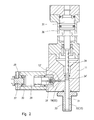
- FIG. 2 is a longitudinal sectional view according to line 2 - 2 of FIG. 1 ;
- FIG. 3 is a cross sectional view of FIG. 1 ;
- FIG. 4 is an enlarged particular of FIG. 3 ;
- FIG. 5 is an enlarged sectional view according to line 5 - 5 of FIG. 3 ;
- FIG. 6 is a section according to line 6 - 6 of FIG. 5 ;
- FIG. 7 is showing the cleaning and valving member for the pressure chamber, seen according to line 7 - 7 of FIG. 8 ;
- FIG. 8 is a sectional view, according to line 8 - 8 of FIG. 7 ;
- FIG. 9 is a second embodiment of the cleaning and valving member for the pressure chamber, seen according to line 9 - 9 of FIG. 10 ;
- FIG. 10 is a sectional view, according to line 10 - 10 of FIG. 9 ;
- FIG. 11 is a third embodiment of the cleaning and valve member for the pressure chamber, seen according to line 11 - 11 of FIG. 12 ;
- FIG. 12 is a sectional view, according to line 12 - 12 of FIG. 11 ;
- FIG. 13 shows a second embodiment of the mixing device according to the invention, provided with a self-cleaning spray nozzle, and with a throttling device for setting the restriction of the injection orifice, which is manually adjustable;
- FIG. 14 shows a mixing device similar to that of FIG. 13 , provided with a throttling device for setting the restriction of the injection orifice, which is automatically adjustable;
- FIG. 15 is a view of the spray nozzle of the device of FIGS. 13 and 14 , seen according to line 15 - 15 of FIG. 16 ;
- FIG. 16 is a sectional view according to line 16 - 16 of FIG. 15 ;
- FIG. 17 is a sectional view according to line 17 - 17 of FIG. 16 ;
- FIGS. 18, 19 and 20 show perspective views of three possible solutions for of the cleaning member for the mixing chamber and for throttling and setting the restriction of the injection orifice.
- FIGS. 1 to 6 a first preferential embodiment of a self-cleaning high-pressure mixing device and high-pressure mixing method according to the present invention will be disclosed.
- the mixing device 10 comprises a body 11 provided with a first cylindrical chamber 12 , also referred to as pressure chamber, in which a first A and at least a second B chemically reactive polymeric components, for example a polyol and an isocyanate are simultaneously supplied and maintained in a substantially unmixed condition, or state, at a same pressure, whilst they flow through a settable restriction of a co-injection orifice 27 , to be co-injected at a same high-pressure in the unmixed state into a cylindrical mixing chamber 19 to form a resulting polymeric mixture.
- a first A and at least a second B chemically reactive polymeric components for example a polyol and an isocyanate
- the term “pressure chamber” means a large feeding chamber in which the polymeric reactive components are firstly fed and maintained in an unmixed state, at a same high-pressure equal to or higher than 40-60 bar (4-6 MPa) and very close to the pumping high-pressure (from 2 to 25 bar due to the pressure drop caused by the feeding the piping), and in which the polymeric reactive components are flowing at the same high-pressure, in an unmixed state, toward a restricted open section of a co-injection orifice which can be set to allow the unmixed reactive components to be co-injected at a same pressure through a restriction, causing a pressure drop through the co-injection orifice higher than 40-60 bar (4-6 MPa) and successively mixed into a smaller mixing chamber.
- the “pressure chamber” substantially differs from a mixing chamber comparatively smaller than a second chamber or discharge conduit of a conventional high-pressure mixing device in which the polymeric reactive components are firstly injected into the mixing chamber in which the pressure is much lower that the feeding pressure (from 60 to 200 bar ⁇ 6.20 MPa), where they are mixed by impingement and flowing at a very low pressure, lower than 4-5 bar (0.4-0.5 MPa) compared to the 40-60 bar (4-6 MPa) or higher of the pressure chamber according to the present invention.
- the polymeric components A and B are supplied simultaneously to the pressure chamber 12 through respective inlet conduits 13 and 14 of a respective feeding line that, through an intermediate chamber 15 , 16 , communicate with respective inlet holes 13 ′ and 14 ′; still in FIG. 3 plugs 17 and 18 have been indicated, that are screwably moveable between a retracted position of FIG. 3 in which open the inlet holes 13 ′ and 14 ′ for the polymeric components A and B, and an advanced or closing position, not shown.
- the plugs 17 and 18 are initially used to conduct a check for setting the metering pumps for the polymeric components A, B, for example by closing the inlet hole of one of the polymeric components, leaving the other inlet hole open, to separately feed a stoichiometric quantity of each single polymeric component, measuring the quantity by weight.
- a first cleaning and valving member 20 is reciprocated between a retracted and an advanced position; the cleaning member 20 is configured with longitudinal slots 21 , 22 ( FIG. 3 ) which in the advanced position of the valve member 20 , put into communication each inlet hole 13 ′, 14 ′ of each single polymeric components A, B, with a respective recirculating conduit 23 and 24 .
- the valving member 20 in addition to the function of opening/closing the inlet holes 13 ′, 14 ′, and recirculating the polymeric components A, B, also performs a complementary function as first cleaning member, to eject into the mixing chamber 19 the unmixed components A and B that remain in the common pressure chamber 12 at the end of each mixing step.
- the reciprocal movement between the retracted position and the advanced position of the first cleaning and valving element 20 as shown in FIGS.
- the pressure chamber 12 via a settable restriction or narrowed co-injection orifice 27 of elliptical shape, FIGS. 5 and 6 , opens towards a transversely oriented mixing chamber 19 having a diameter D 2 that is comparatively lower than the diameter D 1 of the pressure chamber 12 , for example equal to at least one half said diameter D 1 of the pressure chamber 12 ;
- the angular orientation and the transversal arrangement of the longitudinal axis of the mixing chamber 19 , with respect to the longitudinal axis of the pressure chamber 12 can be any depending on the specific constructional and functional requirements of the mixing device.
- the mixing chamber 19 is arranged orthogonally, at 90°, with respect to the pressure chamber 12 ; nevertheless, it cannot be ruled out that the mixing chamber 19 can be differently arranged and angularly oriented, maintaining a condition of partial or total interference with a forwardly convergent or conical portion 12 ′ at the fore end of the common pressure chamber 12 , as shown in FIGS. 4 and 5 .
- a second cleaning member 28 slides, operatively connected to the piston 29 of a second hydraulic actuator 30 , to be moved between a settable retracted position, shown in FIG. 2 , in which opens the mixing chamber 19 towards a delivery conduit 31 , and in which throttles the elongated restriction of the co-injection orifice 27 , and an advanced position forward the co-injection orifice 27 in which closes the mixing chamber 19 towards the delivery conduit 31 , ejecting the resulting residual mixture.
- the delivery conduit 31 can be differently configured and oriented with respect to the mixing chamber 19 ; in the case shown, the delivery conduit 31 consists of a cylindrical bush 32 the internal diameter D 3 of which is comparatively greater and at least twice greater than the diameter D 2 of the mixing chamber 19 .
- the cylindrical bush 32 is oriented orthogonally at 90° to the mixing chamber 19 ; the bush 32 is retained in a seat of the body 11 by a sleeve 33 . Both the sleeve 33 and the bush 32 are removably fastened to the body 11 of the device to permit suitable maintenance and/or replacement operations.
- a third cleaning member slides, for example consisting of a stem 34 provided with an enlarged piston head 34 ′, operatively connected to the piston member 35 of a third hydraulic actuator 36 .
- a suitable hydraulic circuit operatively connected to a control unit of the entire mixing device, coordinates the correct sequence of the operative movements of the three hydraulic actuators 26 , 30 and 36 .
- the pressure chamber 12 is also angularly oriented with respect to the delivery conduit 31 ; in this manner, an arrangement is obtained of the common pressure chamber 12 , of the mixing chamber 19 and the delivery conduit 31 , according to three different axes or vectorial directions, which permits a better mixing degree of the polymeric components A, B and a great damping of the turbulence in the delivered flow of the resulting mixture.
- a further feature that is distinguishing the present invention consists of the possibility of configuring the mixing chamber 12 with a diameter D 2 comparatively lower than the diameter D 1 of the pressure chamber 12 , maintaining a D 1 /D 2 ratio comprised between 1.4 and 15 depending on the number of polymeric components to be mixed.
- the polymeric components A, B that are in an unmixed state in the pressure chamber 12 are co-injected into a mixing chamber 12 of reduced dimensions, undergoing an impact and an angular deviation at the opposite side at an average speed that increases with the square of D 1 /D 2 ratio.
- This enables the kinetic energy and the turbulence induced in the flow of co-injected reactive components A, B, to be exploited to the maximum and maintained by the disposition and the reduced section of the mixing chamber, obtaining an intimate mixture of the co-injected components.
- the invention is thus directed to a self-cleaning mixing device, of the high-pressure type, able to operate with pressures for feeding the single polymeric components A, B lower than the feeding high-pressure normally required in conventional high-pressure mixing apparatuses, assuring at a same time, a constant control of the mixing degree also in the case of small flowrates, in the order of few grams/second, for example 0.8 grams/second, or of a few tenths of gram/second, as well gradually varying the flowrates by maintaining a high-pressure drop between the pressure chamber and mixing chamber, e.g. above 40 bar (4 Pa), owing to the setting of the open section of the elongated restriction of the co-injection orifice 27 , by retracted opening position of the second cleaning member 28 .
- the pressure chamber 12 has a forwardly converging fore portion 12 ′, for example a conical portion or anyway configured converging towards a co-injection orifice 27 provided by a narrowed restricting having an open section that is adjustable by setting the position of the fore end of the cleaning member in the retracted position of the same cleaning member 28 , to generate a great acceleration of the flow of the polymeric components A, B, in an axial direction transverse to the longitudinal axis of the mixing chamber 19 , for example orthogonally oriented or forming an angle greater or less than 90° with respect to the longitudinal axis of the mixing chamber 19 .
- the length and the angle of convergence of the fore portion 12 ′ of the cylindrical pressure chamber 12 , and the interference degree between said convergent fore portion 12 ′ and a side wall of cylindrical mixing chamber 19 , can be selected and changed during the designing, with respect to what is shown, according to specific needs; for example good results have been obtained, as shown in FIG.
- the convergence angle of the fore portion 12 ′ can be equal to or greater than 40°, for example comprised between 40° and 180°, or less, according to the geometrical shape and D 1 /D 2 ratio between the diameters of the pressure and mixing chambers, as will be explained in greater detail below with reference to the examples of FIGS. 7 to 12 .
- the fore end of the cleaning and valve member 20 in turn is configured with a convergent or conical end portion 20 ′ that conforms to the conical shape and convergence of the fore portion 12 ′ of the pressure chamber 12 ;
- the end portion 20 ′ of the cleaning member 20 is further configured with a cross cavity 20 ′′ that extends parallel to the axis of the mixing chamber 19 , and has a curvature radius conforming to the curvature of the elongated restriction of the co-injection orifice 27 and the curvature radius of the internal surface of the side wall of the mixing chamber 19 ; thus in the advanced position of the cleaning member 20 , the cavity 20 ′′ matches and closes the co-injection orifice 27 at one side of the mixing chamber 19 , flush to an internal surface of the side wall, to enable the second cleaning member 28 to slide and eject the remaining mixture at the end of each mixing step.
- the longitudinal axis of the mixing chamber 19 forms with the longitudinal axis of the pressure chamber 12 an angle that can be comprised between 15° and 165°.
- the operation of the mixing device can be as follows: initially both the cleaning member 20 for the pressure chamber 12 and the cleaning member 28 for the mixing chamber 19 are in an advanced closure position; so the polymeric components A and B are recirculated by pumping device in the stoichiometrically requested quantities to respective storage tanks, through the slots 21 , 22 in the first cleaning member 20 and the return conduits 23 , 24 .
- the mixing device is opened; in this manner the polymeric components A, B are fed at the required high-pressure into the pressure chamber 12 , where they flow at a same pressure in a substantially unmixed state along the pressure chamber ( 12 ), and the convergent fore portion 12 ′ to the co-injection orifice 27 .
- the polymeric components A, B still in a unmixed state and at a same pressure, undergo a great acceleration towards and through the settable open section of the restricted orifice 27 , being in this manner co-injected and mixed under strong turbulence and great kinetic energy condition, transversely from a side wall of the mixing chamber 19 against the opposite side thereof where the components A, B are thoroughly and intimately mixed with one another.
- the resulting mixture flows into a delivery conduit 31 having a comparatively greater diameter D 3 , for example with a cross-section two or more times the cross-section of the mixing chamber 19 , to be poured or injected into a mold or poured onto a substrate.
- a diameter D 1 between 3.5 and 32 mm, and a diameter D 2 between 1 and 10 mm, and choosing a diameter D 3 between 4 and 45 mm.
- the pressure of the polymeric components A and B in the common pressure chamber 12 and the kinetic energy of the co-injection jet can be suitably controlled by narrowing the area of the open section of the co-injection orifice 27 by adjusting and setting the fore end of the cleaning member 28 in its retracted condition, in respect to the same co-injection orifice 27 ; as the second cleaning member 28 is physically and operatively separated from the first cleaning and valve member 20 , the operative condition of the second cleaning member 28 for setting the co-injection orifice 27 is no manner influenced by the movement of the first cleaning member 20 , by the control pressure of the hydraulic actuator and by the flowing mixture.
- the retracted operative position of the second cleaning member 28 for setting and throttling the co-injection orifice 27 can thus be stably maintained during operation of the mixing device, or adjusted by varying in relation to the total flowrate of delivered mixture, ensuring a constant control of the pressure inside the pressure chamber 12 and, consequently, a constant control of the mixing degree of the polymeric components A and B.
- the correct positioning of the second cleaning member 28 in the retracted condition for setting and throttling the co-injection orifice 27 can be controlled and adjusted in an extremely simply mode, for example by providing an adjustable stop member or stop means 37 for the piston 29 of the hydraulic actuator 30 , the axial position of which, in the example shown, can be simply changed by screwing and locking the piston 29 in a desired position, for example by a screw 38 , or with any other locking devices suitable for this purpose.
- the stop means 37 can therefore be configured in any way, providing a manual or automatic adjusting system, as explained further on.
- the mixing method accelerates, makes turbulent and maintains in a turbulent state the flow of polymeric components which are co-injected in an unmixed condition into the mixing chamber, by varying and setting the restriction of the co-injection orifice 27 , to generate a pressure drop between the pressure chamber 12 and the mixing chamber 11 equal to or greater than 40-60 bar (4-6 MPa).
- the end portion 20 ′ of the cleaning member 20 and fore portion 12 ′ of the pressure chamber 12 can have any mating and converging configuration, so as to permit in the totally advanced position of the cleaning member 20 , a mating contact of the convergent end portion of the same cleaning member 20 with the fore portion 12 ′ of the pressure chamber 12 .
- a conical configuration has been shown in which the length of the fore portion 12 ′ of the pressure chamber 12 is equal to the radius of the same mixing chamber 19 , with a convergency angle greater than 90°; in fact, the length and the convergency angle of the fore portion 12 ′ of the pressure chamber 12 can also be varied with respect to what has been shown.
- FIGS. 7 and 8 show a second possible convergent shape of the fore portion 12 ′ of the pressure chamber 12 , of the end portion 20 ′ of the cleaning member 20 , and of the convergence angle.
- the same reference numbers have been used as in the previous figures to indicate similar or equivalent parts; further, for reasons of simplicity, some parts have been omitted.
- the fore portion 12 ′ of the pressure chamber 12 is configured with a flat surface 40 , rearwardly slanted with respect to the longitudinal axis of the chamber 12 , which forms with respect to this axis a convergence angle equal to or greater than 30°, for example between 30° and 90°.
- the mixing chamber 19 is again oriented transversely and partially intersects the fore portion 12 ′ of the pressure chamber 12 , forming a narrowed elongated restriction of the injection orifice for the co-injection of the polymeric components A, B, in an unmixed condition.
- the end portion 20 ′ of the cleaning member 20 terminates with a similarly flat slanting surface 41 , to come into a mating contact with the slanted flat surface 40 of the forwardly converging fore portion of the pressure chamber in the totally advanced condition of the cleaning member 20 , to eject the remaining unmixed components A, B from the pressure chamber 12 at the end of each mixing step.
- FIGS. 9 and 10 show a third converging shape of the fore portion 12 ′ of the pressure chamber 12 , of the end portion 20 ′ of the cleaning member 20 , and the respective convergence angle.
- the same reference numbers have again been used as in the previous examples to indicate similar or equivalent parts; further, some parts have been omitted again.
- FIGS. 9 and 10 differs from the preceding solutions because now both the fore portion 12 ′ of the pressure chamber 12 and the end portion 20 ′ of the cleaning member 20 are configured with two flat oppositely slanted surfaces 42 ′, 42 ′′, respectively 43 ′, 43 ′′, which are converging forwards in respect to the longitudinal axis of the pressure chamber 12 , and towards the co-injection orifice 27 , forming a convergence angle equal to or greater than 40°, for example comprised between 40° and 180°.
- a convergence angle equal to or greater than 40°, for example comprised between 40° and 180°.
- a semicylindrical cavity has been shown at the end portion 20 ′ of the cleaning member 20 , that conforms to the co-injection orifice, and to the curvature radius of the side wall of the mixing chamber 19 , in which the cavity 20 ′′ is oriented transversely to the two slanted surfaces 43 ′ and 43 ′′, and extends again parallel to the longitudinal axis of the mixing chamber 19 .
- FIGS. 11 and 12 show a fourth solution that differs from the preceding ones inasmuch as the forwardly converging fore portion 12 ′ of the pressure chamber 12 , and the end portion 20 ′ of the cleaning member 20 , are configured by a semispherical surface 44 and respectively 45 , having a same curvature radius; on the other hand, also the solution of FIGS. 11 and 12 comprises the features and operates in the same manner as the previous solutions. Accordingly, also in FIGS. 11 and 12 the same reference numbers as for the preceding figures have been used again to indicate similar or equivalent parts.
- FIG. 13 of the drawings shows a second embodiment of a mixing device 10 according to the invention; in FIG. 13 the same reference numbers as for the preceding figures have been used again to indicate similar or equivalent parts.
- the mixing device 10 was provided with a pressure chamber 12 , with a mixing chamber 19 and with a delivery conduit 31 angularly oriented according to three different vectorial axes.
- the solution of FIG. 13 maintaining all the innovative features of the method and of the mixing device of FIGS. 1 to 6 , differs inasmuch as now the delivery conduit 31 is axially aligned and constitutes an extension of the same diameter as the mixing chamber 19 ; the delivery conduit 31 furthermore terminates with a spray nozzle 46 of the self-cleaning type.
- the cleaning member 28 extends over the entire length of the mixing chamber 19 and the delivery conduit 31 , up to the exit hole 47 of the spray nozzle 46 .
- the mixing device of FIG. 13 has the same innovative features and operates in a very similar manner to the devices previously disclosed.
- the high-pressure mixing device of FIG. 13 is again provided with stop means 37 for the piston 29 of the hydraulic actuator 30 of the cleaning member 28 that sequentially performs the setting of the pressure in the pressure chamber, the cleaning of the mixing chamber 19 , the delivery conduit 31 and the exit hole 47 of the spray nozzle 46 , and in which the stop means 37 can be manually adjusted by screwing in a threaded hole provided at the rear head 30 ′ of the hydraulic actuator 30 .
- a stop means which is automatically adjustable as shown in FIG. 14 , substantially consisting of a slider 37 ′, axially guided into the rear head 30 ′ of the hydraulic actuator 30 ; the slider 37 ′ is operatively connected to an actuator 48 consisting, for example, of an electric or hydraulic actuator.
- the actuator 48 is operatively connected to a control unit 49 configured for calculating and setting the cleaning member 28 in a preset adjusted position; the control unit 49 is able to perform a predictive calculation of the retracted position of the cleaning member 28 to open and throttle the co-injection orifice 27 , both preliminarily, i.e. before delivering the reactive mixture, and during the same delivering step.
- the spray nozzle 46 and the cleaning member 28 can be configured differently; certain embodiments of the spray nozzle 46 and the cleaning member 28 are shown by way of example in FIGS. 15 to 20 .
- the nozzle 46 is configured with an axial bore 47 that is axially aligned to the mixing chamber 19 and to the delivery conduit 31 ; the axial bore 47 partially intersects a V-shaped transverse cut 50 having two divergent flat walls 50 ′ and 50 ′′ that extend from a narrowed orifice 51 , FIG. 15 , to the lower end of the bore 47 .
- the fore end 28 ′ of the cleaning member 28 in the advanced position of the latter come into contact and is matching the internal shaped surface of the lower end 47 ′ of the bore 47 , at the orifice 51 , as shown in FIGS. 16 and 17 , where the space between the cleaning member 28 and the bore 47 , for reasons of clarity, has been deliberately enlarged.
- a self-cleaning high-pressure mixing device is obtained, of the type disclosed, provided with a self-cleaning spray nozzle 46 that does not require the use of air jets to be cleaned, inasmuch as it is able to eject all the residual mixture in the mixing chamber 19 and in the bore 47 of the nozzle 46 .
- the end 28 ′ of the cleaning member 28 intended to come into contact with and matching the shaped inside end of the bore 47 can have any conformation; for example in FIGS. 16, 17 and in the detail of FIG. 18 , the end 28 ′ of the cleaning member 28 is conformed as a cap having, on two sides, a semicylindrical surface 28 ′′ the axis of which is oriented orthogonally to the longitudinal axis of the cleaning member 28 .
- FIGS. 19 and 20 show two further embodiment of the fore end 28 ′ of the cleaning member 28 , also intended to come into contact with and conform to a suitable shaped surface inside the bore 47 .
- the end 28 ′ of the cleaning member 28 is configured again as a cap 28 ′′′ with a toric shape, that substantially consists of a quarter torus; otherwise, according to the solution of FIG. 20 , the fore end 28 ′ of the cleaning member 28 , terminates with a spherical cap 28 IV which, as in the preceding examples, is meshing to the cylindrical surface of the cleaning member 28 .
- the mixing device is further characterized by comprising a mixing chamber 19 that extends in a cylindrical delivery conduit provided with a self-cleaning spray nozzle for a resulting polymeric mixture, in which the cleaning member of the mixing chamber, in the advanced position thereof, extends in the delivery conduit and through an eject bore of the spray nozzle, configuring the fore end of the cleaning member of the mixing chamber with a shape that conforms to and match an internal surface of the ejection bore.
Landscapes
- Engineering & Computer Science (AREA)
- Mechanical Engineering (AREA)
- Chemical & Material Sciences (AREA)
- Chemical Kinetics & Catalysis (AREA)
- Processing And Handling Of Plastics And Other Materials For Molding In General (AREA)
- Injection Moulding Of Plastics Or The Like (AREA)
Applications Claiming Priority (2)
| Application Number | Priority Date | Filing Date | Title |
|---|---|---|---|
| ITMI2013A002189 | 2013-12-23 | ||
| IT002189A ITMI20132189A1 (it) | 2013-12-23 | 2013-12-23 | Metodo e apparecchiatura di miscelazione ad alta pressione per la co-iniezione di componenti polimerici |
Publications (2)
| Publication Number | Publication Date |
|---|---|
| US20150174540A1 US20150174540A1 (en) | 2015-06-25 |
| US10040040B2 true US10040040B2 (en) | 2018-08-07 |
Family
ID=50190551
Family Applications (1)
| Application Number | Title | Priority Date | Filing Date |
|---|---|---|---|
| US14/580,573 Expired - Fee Related US10040040B2 (en) | 2013-12-23 | 2014-12-23 | Method and high-pressure mixing device for the co-injection of polymeric components |
Country Status (3)
| Country | Link |
|---|---|
| US (1) | US10040040B2 (it) |
| EP (1) | EP2886280B1 (it) |
| IT (1) | ITMI20132189A1 (it) |
Families Citing this family (7)
| Publication number | Priority date | Publication date | Assignee | Title |
|---|---|---|---|---|
| ITMI20130216A1 (it) | 2013-02-15 | 2014-08-16 | Afros Spa | Metodo e apparecchiatura di miscelazione ad alta pressione con tenuta autorigenerante |
| ITMI20132189A1 (it) * | 2013-12-23 | 2015-06-24 | Afros Spa | Metodo e apparecchiatura di miscelazione ad alta pressione per la co-iniezione di componenti polimerici |
| IT201800010844A1 (it) * | 2018-12-05 | 2020-06-05 | Afros Spa | Elemento a guarnizione di tenuta per un’apparecchiatura di miscelazione, metodo di ottenimento ed applicazione dello stesso e relativa attrezzatura speciale di montaggio. |
| IT201900004603A1 (it) * | 2019-03-27 | 2020-09-27 | Afros Spa | Dispositivo di miscelazione ad alta pressione con condotto di erogazione in singolo pezzo |
| IT201900010524A1 (it) * | 2019-07-01 | 2021-01-01 | Afros Spa | Testa di miscelazione e dosaggio monitorata |
| EP4041512A1 (de) | 2019-10-08 | 2022-08-17 | Covestro Intellectual Property GmbH & Co. KG | Vorrichtung zur vermischung reaktiver komponenten |
| CN116196844B (zh) * | 2023-04-15 | 2023-08-11 | 南通星球石墨股份有限公司 | 一种用于石墨反应釜的进料装置 |
Citations (20)
| Publication number | Priority date | Publication date | Assignee | Title |
|---|---|---|---|---|
| US4332335A (en) | 1978-03-09 | 1982-06-01 | Afros S.R.L. | Head for mixing and ejecting interacting liquid components, for molding plastic materials |
| DE3427327A1 (de) * | 1983-07-27 | 1985-02-07 | Elastogran Maschinenbau GmbH, 2844 Lemförde | Mischkopf zum erzeugen eines vorzugsweise chemisch reaktionsfaehigen gemisches aus mindestens zwei kunststoffkomponenten |
| US4608233A (en) | 1982-04-06 | 1986-08-26 | Afros S.P.A. | Mixing method and apparatus for preparing multi-component plastic materials especially polyurethanes |
| US4721391A (en) * | 1985-04-01 | 1988-01-26 | Krauss-Maffei A.G. | Impingement mixing device with auxiliary input and process for producing plastic parts |
| US4802770A (en) | 1986-09-25 | 1989-02-07 | Afros S.P.A. | High pressure mixing device |
| EP0391152A1 (en) | 1989-04-03 | 1990-10-10 | Kabushiki Kaisha Polyurethane Engineering | Apparatus for mixing composite synthetic resin |
| EP0447883A1 (de) * | 1990-03-23 | 1991-09-25 | Krauss-Maffei Aktiengesellschaft | Vorrichtung und Verfahren zum Mischen von wenigstens zwei reaktiven Kunststoffkomponenten |
| US5164162A (en) * | 1990-05-21 | 1992-11-17 | The Dow Chemical Company | Mixing head with sleeved quieting chamber |
| DE9315493U1 (de) | 1993-10-08 | 1993-12-23 | Afros Spa | Hochdruck-Mischkopf mit einstellbarem Durchflußbegrenzer |
| US5277567A (en) * | 1990-03-23 | 1994-01-11 | Krauss Maffei Ag | Apparatus for mixing reactive synthetic-resin components |
| US5453249A (en) * | 1992-04-06 | 1995-09-26 | Maschinenfabrik Hennecke Gmbh | Apparatus for producing a flowable reaction mixture from at least two flowable reaction components |
| US5498151A (en) | 1993-05-05 | 1996-03-12 | Nennecker; Gunter H. | Mixing head for molding machine |
| US6079867A (en) * | 1997-05-22 | 2000-06-27 | Afros S.P.A. | Self-cleaning, mixing apparatus and method for the production of polyurethane formulations |
| US20010001602A1 (en) | 1997-08-05 | 2001-05-24 | Alberto Bonansea | Apparatus for the production of polyurethane material |
| WO2004041494A1 (en) | 2002-11-05 | 2004-05-21 | Afros S.P.A. | Co-injection mixing method and apparatus |
| US20080094936A1 (en) | 2006-06-21 | 2008-04-24 | Afros S.P.A. | Method and apparatus with lobed nozzles, for mixing reactive chemical components |
| EP1992466A2 (de) | 2007-05-18 | 2008-11-19 | FRIMO Group GmbH | Verfahren und Vorrichtung zur Herstellung eines Polyurethans aus zwei unter hohem Druck stehenden Ausgangskomponenten |
| US20100137508A1 (en) * | 2008-12-03 | 2010-06-03 | Afros S.P.A. | Method and high-pressure mixing device for filled polyurethane resins |
| US20150174540A1 (en) * | 2013-12-23 | 2015-06-25 | Afros S.P.A. | Method and High-Pressure Mixing Device for the Co-Injection of Polymeric Components |
| US9308512B2 (en) * | 2013-02-15 | 2016-04-12 | Afros S.P.A. | Method and high-pressure mixing apparatus with self-regenerating seal |
Family Cites Families (1)
| Publication number | Priority date | Publication date | Assignee | Title |
|---|---|---|---|---|
| US9328241B2 (en) | 2012-09-12 | 2016-05-03 | Sabic Global Technologies B.V. | Thermoplastic polyimide as flow promoter and flame retardant synergist for filled polyamide compositions |
-
2013
- 2013-12-23 IT IT002189A patent/ITMI20132189A1/it unknown
-
2014
- 2014-12-19 EP EP14199216.4A patent/EP2886280B1/en not_active Not-in-force
- 2014-12-23 US US14/580,573 patent/US10040040B2/en not_active Expired - Fee Related
Patent Citations (23)
| Publication number | Priority date | Publication date | Assignee | Title |
|---|---|---|---|---|
| US4332335A (en) | 1978-03-09 | 1982-06-01 | Afros S.R.L. | Head for mixing and ejecting interacting liquid components, for molding plastic materials |
| US4608233A (en) | 1982-04-06 | 1986-08-26 | Afros S.P.A. | Mixing method and apparatus for preparing multi-component plastic materials especially polyurethanes |
| DE3427327A1 (de) * | 1983-07-27 | 1985-02-07 | Elastogran Maschinenbau GmbH, 2844 Lemförde | Mischkopf zum erzeugen eines vorzugsweise chemisch reaktionsfaehigen gemisches aus mindestens zwei kunststoffkomponenten |
| US4721391A (en) * | 1985-04-01 | 1988-01-26 | Krauss-Maffei A.G. | Impingement mixing device with auxiliary input and process for producing plastic parts |
| US4802770A (en) | 1986-09-25 | 1989-02-07 | Afros S.P.A. | High pressure mixing device |
| EP0391152A1 (en) | 1989-04-03 | 1990-10-10 | Kabushiki Kaisha Polyurethane Engineering | Apparatus for mixing composite synthetic resin |
| US5277567A (en) * | 1990-03-23 | 1994-01-11 | Krauss Maffei Ag | Apparatus for mixing reactive synthetic-resin components |
| EP0447883A1 (de) * | 1990-03-23 | 1991-09-25 | Krauss-Maffei Aktiengesellschaft | Vorrichtung und Verfahren zum Mischen von wenigstens zwei reaktiven Kunststoffkomponenten |
| US5164162A (en) * | 1990-05-21 | 1992-11-17 | The Dow Chemical Company | Mixing head with sleeved quieting chamber |
| US5453249A (en) * | 1992-04-06 | 1995-09-26 | Maschinenfabrik Hennecke Gmbh | Apparatus for producing a flowable reaction mixture from at least two flowable reaction components |
| US5498151A (en) | 1993-05-05 | 1996-03-12 | Nennecker; Gunter H. | Mixing head for molding machine |
| DE9315493U1 (de) | 1993-10-08 | 1993-12-23 | Afros Spa | Hochdruck-Mischkopf mit einstellbarem Durchflußbegrenzer |
| US6079867A (en) * | 1997-05-22 | 2000-06-27 | Afros S.P.A. | Self-cleaning, mixing apparatus and method for the production of polyurethane formulations |
| US20010001602A1 (en) | 1997-08-05 | 2001-05-24 | Alberto Bonansea | Apparatus for the production of polyurethane material |
| US7455446B2 (en) * | 2002-11-05 | 2008-11-25 | Afros S.P.A. | Co-injection mixing method and apparatus |
| WO2004041494A1 (en) | 2002-11-05 | 2004-05-21 | Afros S.P.A. | Co-injection mixing method and apparatus |
| US20060104155A1 (en) * | 2002-11-05 | 2006-05-18 | Maurizio Corti | Co-injection mixing method and apparatus |
| US20080094936A1 (en) | 2006-06-21 | 2008-04-24 | Afros S.P.A. | Method and apparatus with lobed nozzles, for mixing reactive chemical components |
| EP1992466A2 (de) | 2007-05-18 | 2008-11-19 | FRIMO Group GmbH | Verfahren und Vorrichtung zur Herstellung eines Polyurethans aus zwei unter hohem Druck stehenden Ausgangskomponenten |
| US20100137508A1 (en) * | 2008-12-03 | 2010-06-03 | Afros S.P.A. | Method and high-pressure mixing device for filled polyurethane resins |
| US9308512B2 (en) * | 2013-02-15 | 2016-04-12 | Afros S.P.A. | Method and high-pressure mixing apparatus with self-regenerating seal |
| US9731267B2 (en) * | 2013-02-15 | 2017-08-15 | Afros S.P.A. | Method and high-pressure mixing apparatus with self-regenerating seal |
| US20150174540A1 (en) * | 2013-12-23 | 2015-06-25 | Afros S.P.A. | Method and High-Pressure Mixing Device for the Co-Injection of Polymeric Components |
Non-Patent Citations (1)
| Title |
|---|
| Search Report of Italian Application MI20132189 dated Aug. 6, 2014. |
Also Published As
| Publication number | Publication date |
|---|---|
| EP2886280A1 (en) | 2015-06-24 |
| ITMI20132189A1 (it) | 2015-06-24 |
| EP2886280B1 (en) | 2016-10-12 |
| US20150174540A1 (en) | 2015-06-25 |
Similar Documents
| Publication | Publication Date | Title |
|---|---|---|
| US10040040B2 (en) | Method and high-pressure mixing device for the co-injection of polymeric components | |
| US7614780B2 (en) | Method and apparatus with lobed nozzles, for mixing reactive chemical components | |
| US20080230002A1 (en) | Sealer Gun | |
| US3936002A (en) | Adjustable spray tip | |
| US20160263593A1 (en) | Adjustable smooth bore nozzle | |
| US6502978B2 (en) | Apparatus for the production of polyurethane material with a cleaning member having a filler feeding channel and an inclined front surface | |
| CN102137743B (zh) | 混合排放装置 | |
| EP2195117B1 (en) | Automatic solvent injection for plural component spray gun | |
| AU2004251453A2 (en) | Method for producing a moulded article comprising a sprayed polyurethane layer | |
| US7455446B2 (en) | Co-injection mixing method and apparatus | |
| US8480290B2 (en) | Self-cleaning high-pressure mixing apparatus for composite material | |
| JP6444163B2 (ja) | スプレーガン | |
| US20100137508A1 (en) | Method and high-pressure mixing device for filled polyurethane resins | |
| JP5773808B2 (ja) | 塗料用スプレーガン | |
| KR101113266B1 (ko) | 탄성코트용 에어스프레이 건 | |
| CN203622689U (zh) | 单活塞杆聚氨酯高压混合头 | |
| JPH0740337A (ja) | 多成分混合用ヘッド装置 | |
| US6250569B1 (en) | Adjustable spraying head | |
| CN205761899U (zh) | 一种聚氨酯发泡喷枪 | |
| CN116328970A (zh) | 一种纳米气泡水生产用喷头及装置 | |
| KR101174907B1 (ko) | 공기제트 충돌형 분무노즐 | |
| EP0379833A1 (en) | Injection molding mixing head and metering valve | |
| JPH0360753A (ja) | 低圧微粒化スプレーガン | |
| KR20160017549A (ko) | 발포 성형용 원료 공급장치 |
Legal Events
| Date | Code | Title | Description |
|---|---|---|---|
| AS | Assignment |
Owner name: AFROS S.P.A., ITALY Free format text: ASSIGNMENT OF ASSIGNORS INTEREST;ASSIGNORS:VOLPATO, MARCO;CORTI, MAURIZIO;REEL/FRAME:034575/0146 Effective date: 20141210 |
|
| STCF | Information on status: patent grant |
Free format text: PATENTED CASE |
|
| FEPP | Fee payment procedure |
Free format text: MAINTENANCE FEE REMINDER MAILED (ORIGINAL EVENT CODE: REM.); ENTITY STATUS OF PATENT OWNER: LARGE ENTITY |
|
| LAPS | Lapse for failure to pay maintenance fees |
Free format text: PATENT EXPIRED FOR FAILURE TO PAY MAINTENANCE FEES (ORIGINAL EVENT CODE: EXP.); ENTITY STATUS OF PATENT OWNER: LARGE ENTITY |
|
| STCH | Information on status: patent discontinuation |
Free format text: PATENT EXPIRED DUE TO NONPAYMENT OF MAINTENANCE FEES UNDER 37 CFR 1.362 |
|
| FP | Lapsed due to failure to pay maintenance fee |
Effective date: 20220807 |