US10039208B2 - Method for cooling a connector system - Google Patents
Method for cooling a connector system Download PDFInfo
- Publication number
- US10039208B2 US10039208B2 US14/953,927 US201514953927A US10039208B2 US 10039208 B2 US10039208 B2 US 10039208B2 US 201514953927 A US201514953927 A US 201514953927A US 10039208 B2 US10039208 B2 US 10039208B2
- Authority
- US
- United States
- Prior art keywords
- cage
- ports
- connector
- module
- thermal
- Prior art date
- Legal status (The legal status is an assumption and is not a legal conclusion. Google has not performed a legal analysis and makes no representation as to the accuracy of the status listed.)
- Active
Links
Images


Classifications
-
- H—ELECTRICITY
- H05—ELECTRIC TECHNIQUES NOT OTHERWISE PROVIDED FOR
- H05K—PRINTED CIRCUITS; CASINGS OR CONSTRUCTIONAL DETAILS OF ELECTRIC APPARATUS; MANUFACTURE OF ASSEMBLAGES OF ELECTRICAL COMPONENTS
- H05K7/00—Constructional details common to different types of electric apparatus
- H05K7/20—Modifications to facilitate cooling, ventilating, or heating
- H05K7/20009—Modifications to facilitate cooling, ventilating, or heating using a gaseous coolant in electronic enclosures
- H05K7/20136—Forced ventilation, e.g. by fans
- H05K7/20145—Means for directing air flow, e.g. ducts, deflectors, plenum or guides
-
- G—PHYSICS
- G02—OPTICS
- G02B—OPTICAL ELEMENTS, SYSTEMS OR APPARATUS
- G02B6/00—Light guides; Structural details of arrangements comprising light guides and other optical elements, e.g. couplings
- G02B6/24—Coupling light guides
- G02B6/42—Coupling light guides with opto-electronic elements
- G02B6/4201—Packages, e.g. shape, construction, internal or external details
- G02B6/4246—Bidirectionally operating package structures
-
- G—PHYSICS
- G02—OPTICS
- G02B—OPTICAL ELEMENTS, SYSTEMS OR APPARATUS
- G02B6/00—Light guides; Structural details of arrangements comprising light guides and other optical elements, e.g. couplings
- G02B6/24—Coupling light guides
- G02B6/42—Coupling light guides with opto-electronic elements
- G02B6/4201—Packages, e.g. shape, construction, internal or external details
- G02B6/4256—Details of housings
- G02B6/426—Details of housings mounting, engaging or coupling of the package to a board, a frame or a panel
- G02B6/4261—Packages with mounting structures to be pluggable or detachable, e.g. having latches or rails
-
- G—PHYSICS
- G02—OPTICS
- G02B—OPTICAL ELEMENTS, SYSTEMS OR APPARATUS
- G02B6/00—Light guides; Structural details of arrangements comprising light guides and other optical elements, e.g. couplings
- G02B6/24—Coupling light guides
- G02B6/42—Coupling light guides with opto-electronic elements
- G02B6/4201—Packages, e.g. shape, construction, internal or external details
- G02B6/4266—Thermal aspects, temperature control or temperature monitoring
- G02B6/4268—Cooling
- G02B6/4269—Cooling with heat sinks or radiation fins
-
- G—PHYSICS
- G02—OPTICS
- G02B—OPTICAL ELEMENTS, SYSTEMS OR APPARATUS
- G02B6/00—Light guides; Structural details of arrangements comprising light guides and other optical elements, e.g. couplings
- G02B6/24—Coupling light guides
- G02B6/42—Coupling light guides with opto-electronic elements
- G02B6/4201—Packages, e.g. shape, construction, internal or external details
- G02B6/4274—Electrical aspects
- G02B6/4284—Electrical aspects of optical modules with disconnectable electrical connectors
-
- H—ELECTRICITY
- H01—ELECTRIC ELEMENTS
- H01R—ELECTRICALLY-CONDUCTIVE CONNECTIONS; STRUCTURAL ASSOCIATIONS OF A PLURALITY OF MUTUALLY-INSULATED ELECTRICAL CONNECTING ELEMENTS; COUPLING DEVICES; CURRENT COLLECTORS
- H01R12/00—Structural associations of a plurality of mutually-insulated electrical connecting elements, specially adapted for printed circuits, e.g. printed circuit boards [PCB], flat or ribbon cables, or like generally planar structures, e.g. terminal strips, terminal blocks; Coupling devices specially adapted for printed circuits, flat or ribbon cables, or like generally planar structures; Terminals specially adapted for contact with, or insertion into, printed circuits, flat or ribbon cables, or like generally planar structures
- H01R12/70—Coupling devices
- H01R12/7005—Guiding, mounting, polarizing or locking means; Extractors
-
- H—ELECTRICITY
- H01—ELECTRIC ELEMENTS
- H01R—ELECTRICALLY-CONDUCTIVE CONNECTIONS; STRUCTURAL ASSOCIATIONS OF A PLURALITY OF MUTUALLY-INSULATED ELECTRICAL CONNECTING ELEMENTS; COUPLING DEVICES; CURRENT COLLECTORS
- H01R13/00—Details of coupling devices of the kinds covered by groups H01R12/70 or H01R24/00 - H01R33/00
- H01R13/66—Structural association with built-in electrical component
- H01R13/665—Structural association with built-in electrical component with built-in electronic circuit
-
- H—ELECTRICITY
- H05—ELECTRIC TECHNIQUES NOT OTHERWISE PROVIDED FOR
- H05K—PRINTED CIRCUITS; CASINGS OR CONSTRUCTIONAL DETAILS OF ELECTRIC APPARATUS; MANUFACTURE OF ASSEMBLAGES OF ELECTRICAL COMPONENTS
- H05K7/00—Constructional details common to different types of electric apparatus
- H05K7/20—Modifications to facilitate cooling, ventilating, or heating
- H05K7/2039—Modifications to facilitate cooling, ventilating, or heating characterised by the heat transfer by conduction from the heat generating element to a dissipating body
-
- Y—GENERAL TAGGING OF NEW TECHNOLOGICAL DEVELOPMENTS; GENERAL TAGGING OF CROSS-SECTIONAL TECHNOLOGIES SPANNING OVER SEVERAL SECTIONS OF THE IPC; TECHNICAL SUBJECTS COVERED BY FORMER USPC CROSS-REFERENCE ART COLLECTIONS [XRACs] AND DIGESTS
- Y10—TECHNICAL SUBJECTS COVERED BY FORMER USPC
- Y10T—TECHNICAL SUBJECTS COVERED BY FORMER US CLASSIFICATION
- Y10T403/00—Joints and connections
- Y10T403/60—Biased catch or latch
Definitions
- the present invention relates to the field of input/output (I/O) connectors, more specifically to I/O connectors that handle higher amounts of power.
- I/O connectors are commonly used in system architectures where it is desirable to pass information between two separate components via a flexible cable. Often a first connector will be mounted to a first circuit board and a second connector will be mounted to a second board and a cable with corresponding mating connectors will be plugged into the first and second connector so as to allow information to pass therebetween. Due to increased end-user needs, there has been a general interest in providing I/O connectors that can handle high data-rates (such as 10 Gbps and greater). Future I/O standards may include a 25 Gbps channel. This is expected to be beneficial, at least in part, because data rates of optical channels are suited to operate at 25 Gbps, thus allowing a one-to-one arrangement.
- a 4X connector (where the X represents a transmit channel and a receive channel) that could operate at 25 Gbps would enable four two-way communication channels of 25 Gbps. While a passive cable would allow the signals to be transmitted for shorter distances, at the frequencies that tend to be used, a passive cable is unsuitable for long-distance communication.
- Such a 4x connector could therefore be coupled to an active module (either active copper or optical) so as to allow for increased cable lengths (optical cables offering the potential for lengths of a kilometer or more, for example).
- a module for example, may need to dissipate more than 3 watts. If there is only one connector, the use of a convention riding heat sink can be sufficient. However, if the 4X connectors are ganged or stacked, it becomes much more challenging to cool the connectors. Therefore, certain individuals would appreciate an improved thermal solution.
- a cage includes a front face that includes a channel and a thermal plate forms a wall that extends from the front face along a bottom of the channel.
- An adjustable biasing system is provided to urge an inserted module toward the thermal plate.
- the thermal plate supports a fin.
- the thermal plate omits fins and is compatible with a convention circuit board layout.
- a housing with a card slot is positioned in the cage so that the card slot is aligned with the channel.
- the adjustable biasing system may be a riding heat sink.
- a module with a edge card can be inserted in the cage so that the edge card is positioned in the card slot.
- FIG. 1 illustrates a perspective view of an embodiment of a connector system.
- FIG. 2 illustrates a partially exploded perspective view of the connector system depicted in FIG. 1 .
- FIG. 3 illustrates a further exploded perspective view of the connector system depicted in FIG. 2 .
- FIG. 4 illustrates a perspective view of a cross-section of an embodiment of receptacle.
- FIG. 5 illustrates an enlarged side view of the cross-section depicted in FIG. 4 .
- FIG. 6A illustrates a perspective view of an embodiment of a cage.
- FIG. 6B illustrates another perspective view of an embodiment of a cage.
- FIG. 6C illustrates a plan view of the cage depicted in FIG. 6A .
- FIG. 6D illustrates a bottom view of the cage depicted in FIG. 6A .
- FIG. 7 illustrates a perspective view of an embodiment of a connector plug and receptacle in an unmated position.
- FIG. 8 illustrates a perspective view of the plug and receptacle depicted in FIG. 7 in a mated position.
- FIG. 9 illustrates an elevated side view of a cross-section of the plug and receptacle depicted in FIG. 8 .
- FIG. 10 illustrates a perspective view of another embodiment of a cage.
- FIG. 11 illustrates another perspective view of the embodiment depicted in FIG. 10 .
- FIG. 12 illustrates a perspective view of a cross-section of the cage depicted in FIG. 10 taken along line 12 - 12 .
- FIG. 13 illustrates a perspective view of another embodiment of a cage.
- FIG. 14 illustrates a perspective view of an embodiment of a connector system.
- FIG. 15 illustrates a perspective view of another embodiment of a connector system.
- FIG. 16 illustrates a perspective view of another embodiment of a connector system.
- FIG. 17 illustrates a perspective view of another embodiment of a connector system.
- one advantage of the system illustrated in FIGS. 1-6D is that when a module 100 (which can be an active module configured to enable an active copper or optical transceiver) is inserted into the cage 60 of a receptacle 50 , a nose portion 110 is sandwiched between a riding heat sink 70 and a thermal plate 64 .
- the riding heat sink is biased toward the thermal plate 64 with a clip 75 that used a retaining flange 79 to engage features on the cage 60 so as secure the clip 75 in place.
- Fingers 77 extend from the clip and press on a plate 73 of heat sink 71 so that surface 78 can make reliable contact with an inserted module and thermal fins 72 can dissipate heat.
- the fingers bias the surface downward toward the thermal plate and thus act as a biasing system to press an inserted module against the thermal plate 64 .
- the thermal plate 64 can be positioned forward of the forward-most vias 34 in a circuit board 30 and as depicted is integral with the cage 60 .
- the cage can also be configured to be compatible with any mechanical system that can adjustably bias an inserted module toward the thermal plate.
- the cage could include a closed top surface that had an adjustable biasing system such as springs that acted to press an inserted module toward the thermal plate.
- the riding heat sink 70 is merely one example of a possible adjustable biasing system and as the use of leaf springs and other biasing systems such as springs and compressible materials is well known is the mechanical arts; no further discussion of the adjustable biasing system is needed.
- the depicted connector system allows thermal energy to be removed from both the top and bottom of the receptacle 50 .
- lower fins 65 can be mounted on the thermal plate 64 .
- fins 65 can be any desired orientation, it being understood that direction air flow over fins 65 is expected to be beneficial of heat dissipation.
- a single receptacle 50 can provide substantially greater surface area to dissipate thermal energy.
- a notch 32 (often referred to as a cut-back) can be provided in the circuit board 30 .
- the fins are optional and may not be suitable for some applications.
- the cage is positioned so as to extend around a housing 90 that includes one or more card slots 91 .
- the card slots 91 have terminals 94 supported by the housing and mounted so as to be provided on both sides of the card slots so as to provide a desired compact receptacle structure/interface.
- a cage slot 69 can be provided that engages with a corresponding flange on the housing 90 .
- the thermal plate 64 has an end 67 that extends back past the opening 93 provided for the card slots 91 , 92 .
- the thermal plate 64 can still allow for access to an alignment slot provided under the card slots, if the alignment slot is provided.
- the thermal plate 64 can have notches 68 that help align the thermal plate 64 with such alignment slots.
- the cage 60 may also have back notches 61 that allow for some thermal energy to dissipate out the rear of the cage 60 and because of their pointed ends, also provide a good interface for being soldered to a pad on a supporting circuit board.
- the thermal plate may be provided to help route thermal energy from the bottom of the inserted module to a portion of the cage that is better configured for thermal dissipation.
- a cage 260 that includes a first side wall 263 a , a second side wall 263 b , a rear wall 263 c and a top wall 268 .
- the cage 260 includes a front face 261 that defines a front of a channel 261 into which a module can be inserted.
- a thermal plate 264 extends back from the front face 261 and includes a plurality of projections 265 that are configured to engage an inserted module. It should be noted that the cage depicted in FIGS. 1-6D did not include the projections 265 .
- the projections 265 provide a number of points of contact with the module and for situations where the module and/or thermal plate is not sufficiently flat, the projections 265 may offer better thermal coupling between the inserted module and the thermal plate then a design of a thermal plate and module were both are intended to be flat but due to tolerances were not.
- the cage includes an alignment slot 267 a and may also include an alignment shoulder 267 b.
- FIG. 13 illustrate another embodiment of a cage 360 that includes the front face 361 with a thermal plate 364 extending back from the front face 361 .
- a thermal coupling bar 365 can be provided to make contact with an inserted module and, like the projections 265 , can offer a higher pressure contact force that helps ensure the thermal plate 364 reliably engages with an inserted module.
- the cage may be intended to be positioned so that there is minimal space below the circuit board, thus making it extremely difficult to provide sufficient air flow under the cage.
- a stacked configuration (particularly a stacked, ganged configuration) could have fins on a top (or even on the top and bottom if a belly-to-belly configuration was used) but would still have a problem dissipating thermal energy from between the two receptacles formed by the stacked configuration.
- a conventional stacked configuration with only the top heat sink all the heat needs to be dissipated through the top of the connector, thus making it difficult to dissipate higher levels of thermal energy possible with active and optical modules.
- FIG. 14 illustrates a 460 configured to provide a ganged connector positioned on a circuit board 430 .
- a thermal conduit 480 is positioned along a lower surface of the cage 460 and can help remove heat from the corresponding receptacle when modules, such as module 491 or module 492 , are inserted therein.
- the each module includes an edge card, such as edge card 493 that is configured to be positioned in the card slot of the corresponding housing.
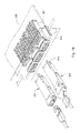
- FIG. 15 depicts a connector system with a cage 560 that is configured for a ganged and stacked configuration.
- a thermal conduit 580 extends through the center of the cage 560 and, in operation, engages a bottom of the upper module and a top of the lower module when the upper and lower module are inserted.
- FIG. 16 illustrates a connector system similar to that depicted in FIG. 15 in that cage 660 is stacked but the cage is not a ganged cage. Furthermore, the lower module 691 is inserted upside down compared to the upper module 691 . The depicted configuration still uses two riding heat sinks but an upper heat sink 670 lower heat sink may be longer in length because of the circuit board.
- a thermal conduit 680 extends through the cage 660 and, because the modules are inserted in opposite orientation, can engage the same surface of the module regardless of whether the module inserted in the upper or lower port.
- FIG. 17 illustrates another embodiment of a connecter system with a cage 760 and a cage 760 ′ mounted on opposite sides of a circuit board 730 .
- the two cages are both configured with riding heat sinks 770 and a thermal conduit 780 extends between the two cages and in line with circuit board 730 .
- the thermal plate can be positioned so as to engage a side of the module that would typically be not in contact with a thermally conductive portion of the receptacle and the thermal conduit can remove heat from the thermal plate.
- the conductive flow through the thermal conduit could be any desirable medium such as a gas or liquid (e.g., air or water).
- a portion (which could range from a small amount to all) of the thermal plate could be replaced with a thermal conduit channel and in an embodiment the thermal conduit could function as the thermal plate for two receptacles that were stacked.
- a top surface of the thermal conduit could engage a first side of a first module and a bottom surface of the thermal conduit could engage a first side of a second module.
Abstract
A cage can include a thermal plate positioned so as to be aligned with a bottom of a channel. An adjustable biasing system is provided to urge a module toward the thermal plate. The adjustable biasing system may be a riding heat sink. The thermal plate may include a fin to help increase its surface area. A housing with a card slot aligned with the channel can be provided in the cage to provide a receptacle that has a card slot aligned with the channel. A receptacle so configured allows for greater thermal energy to be removed from a module.
Description
This application is a continuation of U.S. Ser. No. 13/704,175, filed Mar. 25, 2013, now U.S. Pat. No. 9,246,280, which is a national phase application of PCT Application No. PCT/US11/40155, filed Jun. 13, 2011, which in turn claims priority to U.S. Provisional Application No. 61/355,030, filed Jun. 15, 2010, all of which are incorporated herein by reference in their entirety.
Field of the Invention
The present invention relates to the field of input/output (I/O) connectors, more specifically to I/O connectors that handle higher amounts of power.
Description of Related Art
I/O connectors are commonly used in system architectures where it is desirable to pass information between two separate components via a flexible cable. Often a first connector will be mounted to a first circuit board and a second connector will be mounted to a second board and a cable with corresponding mating connectors will be plugged into the first and second connector so as to allow information to pass therebetween. Due to increased end-user needs, there has been a general interest in providing I/O connectors that can handle high data-rates (such as 10 Gbps and greater). Future I/O standards may include a 25 Gbps channel. This is expected to be beneficial, at least in part, because data rates of optical channels are suited to operate at 25 Gbps, thus allowing a one-to-one arrangement. For example, a 4X connector (where the X represents a transmit channel and a receive channel) that could operate at 25 Gbps would enable four two-way communication channels of 25 Gbps. While a passive cable would allow the signals to be transmitted for shorter distances, at the frequencies that tend to be used, a passive cable is unsuitable for long-distance communication. Such a 4x connector could therefore be coupled to an active module (either active copper or optical) so as to allow for increased cable lengths (optical cables offering the potential for lengths of a kilometer or more, for example).
One potential issue with such a solution, however, is that the use of active modules creates significant thermal energy. A module, for example, may need to dissipate more than 3 watts. If there is only one connector, the use of a convention riding heat sink can be sufficient. However, if the 4X connectors are ganged or stacked, it becomes much more challenging to cool the connectors. Therefore, certain individuals would appreciate an improved thermal solution.
A cage includes a front face that includes a channel and a thermal plate forms a wall that extends from the front face along a bottom of the channel. An adjustable biasing system is provided to urge an inserted module toward the thermal plate. In an embodiment, the thermal plate supports a fin. In another embodiment, the thermal plate omits fins and is compatible with a convention circuit board layout. A housing with a card slot is positioned in the cage so that the card slot is aligned with the channel. In an embodiment, the adjustable biasing system may be a riding heat sink. A module with a edge card can be inserted in the cage so that the edge card is positioned in the card slot.
The present invention is illustrated by way of example and not limited in the accompanying figures in which like reference numerals indicate similar elements and in which:
The detailed description that follows describes exemplary embodiments and is not intended to be limited to the expressly disclosed combination(s). Therefore, unless otherwise noted, features disclosed herein may be combined together to form additional combinations that were not otherwise shown for purposes of brevity.
As depicted, one advantage of the system illustrated in FIGS. 1-6D is that when a module 100 (which can be an active module configured to enable an active copper or optical transceiver) is inserted into the cage 60 of a receptacle 50, a nose portion 110 is sandwiched between a riding heat sink 70 and a thermal plate 64. To create the force needed to ensure a suitable thermal connection, the riding heat sink is biased toward the thermal plate 64 with a clip 75 that used a retaining flange 79 to engage features on the cage 60 so as secure the clip 75 in place. Fingers 77 extend from the clip and press on a plate 73 of heat sink 71 so that surface 78 can make reliable contact with an inserted module and thermal fins 72 can dissipate heat. The fingers bias the surface downward toward the thermal plate and thus act as a biasing system to press an inserted module against the thermal plate 64. The thermal plate 64 can be positioned forward of the forward-most vias 34 in a circuit board 30 and as depicted is integral with the cage 60.
It should be noted that while the riding heat sink design is considered suitable for use with the depicted cage because it provides fingers that can adjustably bias the module toward the thermal plate, the cage can also be configured to be compatible with any mechanical system that can adjustably bias an inserted module toward the thermal plate. For example, the cage could include a closed top surface that had an adjustable biasing system such as springs that acted to press an inserted module toward the thermal plate. Thus, the riding heat sink 70 is merely one example of a possible adjustable biasing system and as the use of leaf springs and other biasing systems such as springs and compressible materials is well known is the mechanical arts; no further discussion of the adjustable biasing system is needed.
As can be appreciated, the depicted connector system allows thermal energy to be removed from both the top and bottom of the receptacle 50. To assist in removal of thermal energy, lower fins 65 can be mounted on the thermal plate 64. It should be noted that if included, fins 65 can be any desired orientation, it being understood that direction air flow over fins 65 is expected to be beneficial of heat dissipation. Thus, a single receptacle 50 can provide substantially greater surface area to dissipate thermal energy. To facilitate the lower fins 65, a notch 32 (often referred to as a cut-back) can be provided in the circuit board 30. However, as will be discussed further below, the fins are optional and may not be suitable for some applications.
As can be appreciated, the cage is positioned so as to extend around a housing 90 that includes one or more card slots 91. The card slots 91 have terminals 94 supported by the housing and mounted so as to be provided on both sides of the card slots so as to provide a desired compact receptacle structure/interface. In preferred embodiments, there is a first card slot 91 and a second card slot 92. To help ensure the cage and housing are aligned, a cage slot 69 can be provided that engages with a corresponding flange on the housing 90.
As can be appreciated from FIG. 5 , the thermal plate 64 has an end 67 that extends back past the opening 93 provided for the card slots 91, 92. The thermal plate 64, however, can still allow for access to an alignment slot provided under the card slots, if the alignment slot is provided. The thermal plate 64 can have notches 68 that help align the thermal plate 64 with such alignment slots. The cage 60 may also have back notches 61 that allow for some thermal energy to dissipate out the rear of the cage 60 and because of their pointed ends, also provide a good interface for being soldered to a pad on a supporting circuit board.
While fins are suitable for transferring thermal energy in certain applications, in other system architectures it can be challenging to provide sufficient air flow. Furthermore, in certain applications there is insufficient space for fins and/or there is little or no air flow over the lower portion of the circuit board. In such a situation, the thermal plate may be provided to help route thermal energy from the bottom of the inserted module to a portion of the cage that is better configured for thermal dissipation.
Looking at FIGS. 10-12 , for example, a cage 260 is disclosed that includes a first side wall 263 a, a second side wall 263 b, a rear wall 263 c and a top wall 268. The cage 260 includes a front face 261 that defines a front of a channel 261 into which a module can be inserted. A thermal plate 264 extends back from the front face 261 and includes a plurality of projections 265 that are configured to engage an inserted module. It should be noted that the cage depicted in FIGS. 1-6D did not include the projections 265. While not required, the projections 265 provide a number of points of contact with the module and for situations where the module and/or thermal plate is not sufficiently flat, the projections 265 may offer better thermal coupling between the inserted module and the thermal plate then a design of a thermal plate and module were both are intended to be flat but due to tolerances were not. As in the prior embodiment, the cage includes an alignment slot 267 a and may also include an alignment shoulder 267 b.
In addition to examples where air flow is difficult to provide, in certain configurations, such as a ganged configuration, the cage may be intended to be positioned so that there is minimal space below the circuit board, thus making it extremely difficult to provide sufficient air flow under the cage. Alternatively, a stacked configuration (particularly a stacked, ganged configuration) could have fins on a top (or even on the top and bottom if a belly-to-belly configuration was used) but would still have a problem dissipating thermal energy from between the two receptacles formed by the stacked configuration. And in a conventional stacked configuration with only the top heat sink all the heat needs to be dissipated through the top of the connector, thus making it difficult to dissipate higher levels of thermal energy possible with active and optical modules.
Therefore, as can be appreciated from FIGS. 14-17 , alternative configurations can provide a channel that directs a thermally conductive flow past an inserted module. FIG. 14 , for example, illustrates a 460 configured to provide a ganged connector positioned on a circuit board 430. A thermal conduit 480 is positioned along a lower surface of the cage 460 and can help remove heat from the corresponding receptacle when modules, such as module 491 or module 492, are inserted therein. As is known, the each module includes an edge card, such as edge card 493 that is configured to be positioned in the card slot of the corresponding housing.
In either a ganged or stacked configuration, therefore, the thermal plate can be positioned so as to engage a side of the module that would typically be not in contact with a thermally conductive portion of the receptacle and the thermal conduit can remove heat from the thermal plate. As can be appreciated, the conductive flow through the thermal conduit could be any desirable medium such as a gas or liquid (e.g., air or water). In addition, if desired, a portion (which could range from a small amount to all) of the thermal plate could be replaced with a thermal conduit channel and in an embodiment the thermal conduit could function as the thermal plate for two receptacles that were stacked. For example, in the stacked configuration a top surface of the thermal conduit could engage a first side of a first module and a bottom surface of the thermal conduit could engage a first side of a second module.
The disclosure provided herein describes features in terms of preferred and exemplary embodiments thereof. Numerous other embodiments, modifications and variations within the scope and spirit of the disclosure will occur to persons of ordinary skill in the art from a review of this disclosure.
Claims (6)
1. A method of cooling a connector system, comprising:
providing a connector on a circuit board, the connector including a cage that extends around a housing, the housing supporting at least two card slots on a front of the housing, the at least two card slots being spaced apart in a vertical manner, the cage defining two ports that are each respectively aligned with one of the at least two card slots, the ports being defined by walls and configured to allow a mating module to be inserted therein in a first direction so as to allow for engagement with the housing;
providing a thermal conduit between the two ports that allows air to flow substantially unhindered by the cage past the two ports in a direction that is transverse to the first direction and then out of the cage; and
directing air through the thermal conduit.
2. The method of claim 1 , wherein the connector includes at least one thermal plate aligned with the thermal conduit and configured to engage an inserted module.
3. The method of claim 1 , wherein the connector further includes at least one riding heat sink.
4. The method of claim 1 , wherein the connector is a ganged connector that includes two columns of ports, each column having two ports that are vertically separated and the thermal conduit extends between the vertically separated ports.
5. The method of claim 1 , wherein the connector includes at least three columns of ports, each column having two ports that are vertically separated and the thermal conduit extends between the vertically separated ports.
6. The method of claim 1 , wherein the thermal conduit is configured to directly contact the mating module when the mating module is inserted into the respective port.
Priority Applications (1)
| Application Number | Priority Date | Filing Date | Title |
|---|---|---|---|
| US14/953,927 US10039208B2 (en) | 2010-06-15 | 2015-11-30 | Method for cooling a connector system |
Applications Claiming Priority (4)
| Application Number | Priority Date | Filing Date | Title |
|---|---|---|---|
| US35503010P | 2010-06-15 | 2010-06-15 | |
| PCT/US2011/040155 WO2011159599A2 (en) | 2010-06-15 | 2011-06-13 | Cage, receptacle and system for use therewith |
| US201313704175A | 2013-03-25 | 2013-03-25 | |
| US14/953,927 US10039208B2 (en) | 2010-06-15 | 2015-11-30 | Method for cooling a connector system |
Related Parent Applications (2)
| Application Number | Title | Priority Date | Filing Date |
|---|---|---|---|
| PCT/US2011/040155 Continuation WO2011159599A2 (en) | 2010-06-15 | 2011-06-13 | Cage, receptacle and system for use therewith |
| US13/704,175 Continuation US9246280B2 (en) | 2010-06-15 | 2011-06-13 | Cage, receptacle and system for use therewith |
Publications (2)
| Publication Number | Publication Date |
|---|---|
| US20160081221A1 US20160081221A1 (en) | 2016-03-17 |
| US10039208B2 true US10039208B2 (en) | 2018-07-31 |
Family
ID=45348807
Family Applications (2)
| Application Number | Title | Priority Date | Filing Date |
|---|---|---|---|
| US13/704,175 Active 2032-02-08 US9246280B2 (en) | 2010-06-15 | 2011-06-13 | Cage, receptacle and system for use therewith |
| US14/953,927 Active US10039208B2 (en) | 2010-06-15 | 2015-11-30 | Method for cooling a connector system |
Family Applications Before (1)
| Application Number | Title | Priority Date | Filing Date |
|---|---|---|---|
| US13/704,175 Active 2032-02-08 US9246280B2 (en) | 2010-06-15 | 2011-06-13 | Cage, receptacle and system for use therewith |
Country Status (3)
| Country | Link |
|---|---|
| US (2) | US9246280B2 (en) |
| TW (1) | TWI533529B (en) |
| WO (1) | WO2011159599A2 (en) |
Cited By (1)
| Publication number | Priority date | Publication date | Assignee | Title |
|---|---|---|---|---|
| US20220285879A1 (en) * | 2021-03-02 | 2022-09-08 | Dongguan Luxshare Technologies Co., Ltd | Interface connector |
Families Citing this family (64)
| Publication number | Priority date | Publication date | Assignee | Title |
|---|---|---|---|---|
| CN104350645B (en) * | 2012-05-04 | 2016-04-20 | 莫列斯公司 | Connector system in groups |
| US9063305B2 (en) * | 2012-11-26 | 2015-06-23 | Avago Technologies General Ip (Singapore) Pte. Ltd. | Methods and systems for dissipating heat in optical communications modules |
| US10375859B2 (en) * | 2013-06-26 | 2019-08-06 | Molex, Llc | Ganged shielding cage with thermal passages |
| US9761974B2 (en) * | 2013-08-16 | 2017-09-12 | Molex, Llc | Connector with thermal management |
| US20150077937A1 (en) * | 2013-09-13 | 2015-03-19 | Alcatel Lucent | Apparatus for cooling board mounted optical modules |
| US9509092B2 (en) * | 2013-11-06 | 2016-11-29 | Cisco Technology, Inc. | System and apparatus for network device heat management |
| CN104979678B (en) * | 2014-04-10 | 2018-04-17 | 泰科电子(上海)有限公司 | Connector shell component and there is its connector |
| US9536680B2 (en) * | 2014-06-18 | 2017-01-03 | Eaton Corporation | Electrical switching apparatus, and jumper and associated method therefor |
| US9653824B2 (en) * | 2015-04-10 | 2017-05-16 | Maxwell Technologies, Inc. | Reduced temperature energy storage device |
| US9857541B2 (en) * | 2015-07-23 | 2018-01-02 | Finisar Corporation | Component alignment |
| CN110632717A (en) | 2015-09-10 | 2019-12-31 | 申泰公司 | Rack-mounted equipment with high heat dissipation modules and transceiver jacks with increased cooling |
| EP3378293B1 (en) * | 2015-11-20 | 2023-06-07 | Laird Technologies, Inc. | Board level shield including an integrated heat sink |
| US9869837B2 (en) * | 2015-12-08 | 2018-01-16 | Te Connectivity Corporation | Heat dissipating communication system |
| CN106025669B (en) * | 2015-12-17 | 2023-09-05 | 温州意华接插件股份有限公司 | Hot plug type interface connector |
| US9910231B2 (en) * | 2016-01-04 | 2018-03-06 | Infinera Corporation | Stacked cage optical module heat relay system |
| WO2017188971A1 (en) | 2016-04-29 | 2017-11-02 | Hewlett Packard Enterprise Development Lp | First and second shields for thermal isolation |
| US10965333B2 (en) * | 2016-07-26 | 2021-03-30 | Laird Technologies, Inc. | Thermal management assemblies suitable for use with transceivers and other devices |
| US9924615B2 (en) * | 2016-08-15 | 2018-03-20 | Te Connectivity Corporation | Receptacle assembly having a heat exchanger |
| EP3497755A4 (en) | 2016-08-15 | 2020-03-25 | Samtec, Inc. | Anti-backout latch for interconnect system |
| US9851519B1 (en) | 2016-11-04 | 2017-12-26 | Ciena Corporation | Optic module cage assembly utilizing a stationary heatsink |
| EP3548945A1 (en) * | 2016-12-02 | 2019-10-09 | Telefonaktiebolaget LM Ericsson (PUBL) | A connector system |
| WO2018132437A1 (en) * | 2017-01-12 | 2018-07-19 | Samtec, Inc. | Cage with an attached heatsink |
| JP7179824B2 (en) | 2017-04-10 | 2022-11-29 | サムテック インコーポレイテッド | Interconnect system with retention features |
| US10551581B2 (en) * | 2017-04-20 | 2020-02-04 | Mellanox Technologies, Ltd. | Optical connector cage with enhanced thermal performance |
| US10921536B2 (en) | 2017-05-18 | 2021-02-16 | Arista Networks, Inc. | Heat sink for optical transceiver |
| WO2018226805A1 (en) | 2017-06-07 | 2018-12-13 | Samtec, Inc. | Transceiver assembly array with fixed heatsink and floating transceivers |
| TW201921809A (en) | 2017-07-07 | 2019-06-01 | 美商安芬諾股份有限公司 | Asymmetric latches for pluggable transceivers |
| US10295767B2 (en) * | 2017-07-20 | 2019-05-21 | Quanta Computer Inc. | Spoiler heat sink device in belly-to-belly transceiver |
| US10439307B2 (en) * | 2017-07-26 | 2019-10-08 | Hewlett Packard Enterprise Development Lp | Cuts in a circuit board |
| TWI790268B (en) | 2017-08-03 | 2023-01-21 | 美商安芬諾股份有限公司 | Connector for low loss interconnection system and electronic system comprising the same |
| CN207266479U (en) * | 2017-08-11 | 2018-04-20 | 泰科电子(上海)有限公司 | Radiator clamping device and the electronic equipment assembly including the clamping device |
| KR102386423B1 (en) * | 2017-09-21 | 2022-04-15 | 몰렉스 엘엘씨 | heat sink with protection lamp |
| US10320113B2 (en) | 2017-10-17 | 2019-06-11 | Mellanox Technologies, Ltd. | Cage receptacle assembly with heat dissipation units |
| USD886066S1 (en) | 2017-12-06 | 2020-06-02 | Samtec, Inc. | Securement member of electrical connector |
| CN109991704A (en) * | 2018-01-02 | 2019-07-09 | 台达电子工业股份有限公司 | Optical transceiver module |
| CN110031940B (en) * | 2018-01-05 | 2021-01-19 | 台达电子工业股份有限公司 | Optical module plugging device |
| US10651598B2 (en) * | 2018-03-22 | 2020-05-12 | Quanta Computer Inc. | Transceiver hot swap contact structure |
| US20190387650A1 (en) * | 2018-06-14 | 2019-12-19 | Cisco Technology, Inc. | Heat sink for pluggable module cage |
| US10575442B2 (en) * | 2018-07-06 | 2020-02-25 | Te Connectivity Corporation | Heat sink assembly for an electrical connector |
| JP2020035800A (en) * | 2018-08-27 | 2020-03-05 | 富士通株式会社 | Connection cage |
| US11088715B2 (en) * | 2018-08-31 | 2021-08-10 | TE Connectivity Services Gmbh | Communication system having a receptacle cage with an airflow channel |
| US10797417B2 (en) | 2018-09-13 | 2020-10-06 | Amphenol Corporation | High performance stacked connector |
| CN208862209U (en) | 2018-09-26 | 2019-05-14 | 安费诺东亚电子科技(深圳)有限公司 | A kind of connector and its pcb board of application |
| CN111338032A (en) * | 2018-12-18 | 2020-06-26 | 中兴通讯股份有限公司 | Optical module communication assembly |
| US10993352B2 (en) | 2019-01-08 | 2021-04-27 | Te Connectivity Corporation | Thermal transfer device for a pluggable module assembly |
| US11122705B2 (en) * | 2019-01-14 | 2021-09-14 | Cisco Technology, Inc. | Liquid cooled optical cages for optical modules |
| WO2020154526A1 (en) | 2019-01-25 | 2020-07-30 | Fci Usa Llc | I/o connector configured for cabled connection to the midboard |
| CN116247455A (en) | 2019-01-25 | 2023-06-09 | 富加宜(美国)有限责任公司 | Electric connector |
| WO2020172395A1 (en) | 2019-02-22 | 2020-08-27 | Amphenol Corporation | High performance cable connector assembly |
| TWI732491B (en) * | 2019-03-19 | 2021-07-01 | 美商莫仕有限公司 | Computing box and its card components |
| TWI735857B (en) * | 2019-03-29 | 2021-08-11 | 佳必琪國際股份有限公司 | Pluggable connector housing structure |
| US10651607B1 (en) * | 2019-05-21 | 2020-05-12 | Arista Networks, Inc. | Stacked optical module cage with improved airflow to bottom ports |
| US10925182B2 (en) | 2019-07-19 | 2021-02-16 | Te Connectivity Corporation | Dual heat transfer assembly for a receptacle assembly |
| US10942323B1 (en) * | 2019-09-20 | 2021-03-09 | Inphi Corporation | Apparatus and method for thermal dissipation of photonic transceiving module |
| WO2021061916A1 (en) | 2019-09-27 | 2021-04-01 | Fci Usa Llc | High performance stacked connector |
| US11357132B2 (en) | 2020-01-23 | 2022-06-07 | Cisco Technology, Inc. | Air cooled cage design |
| CN113258325A (en) | 2020-01-28 | 2021-08-13 | 富加宜(美国)有限责任公司 | High-frequency middle plate connector |
| TWM599039U (en) * | 2020-02-07 | 2020-07-21 | 貿聯國際股份有限公司 | Connector with fin set |
| US11474312B2 (en) * | 2020-02-28 | 2022-10-18 | Ii-Vi Delaware, Inc. | Optoelectronic module for receiving multiple optical connectors |
| CN111564728B (en) * | 2020-05-25 | 2022-04-26 | 东莞立讯技术有限公司 | Electrical connector |
| US11774693B2 (en) * | 2020-06-10 | 2023-10-03 | Molex, Llc | Optical transceiver modules and heat management techniques therefor |
| US11249264B2 (en) | 2020-07-02 | 2022-02-15 | Google Llc | Thermal optimizations for OSFP optical transceiver modules |
| TWI763212B (en) * | 2020-10-30 | 2022-05-01 | 台灣莫仕股份有限公司 | connector assembly |
| TWI768917B (en) * | 2021-05-21 | 2022-06-21 | 緯創資通股份有限公司 | Receptacle assembly and interface card and electronic device having the same |
Citations (8)
| Publication number | Priority date | Publication date | Assignee | Title |
|---|---|---|---|---|
| US20030161108A1 (en) | 2002-03-06 | 2003-08-28 | Bright Edward John | Pluggable electronic module and receptacle with heat sink |
| US6655995B1 (en) | 2002-07-31 | 2003-12-02 | Tyco Electronics Corporation | Electrical connector receptacle cage with interlocking upper and lower shells |
| US6980437B2 (en) | 2004-03-03 | 2005-12-27 | Tyco Electronics Corporation | Pluggable electronic receptacle with heat sink assembly |
| US20080285236A1 (en) | 2007-05-16 | 2008-11-20 | Tyco Electronics Corporation | Heat transfer system for a receptacle assembly |
| US20090109627A1 (en) | 2007-10-31 | 2009-04-30 | Murr Keith Mcquilkin | Heat sink retaining clip for an electrical connector assembly |
| US7704097B1 (en) * | 2009-02-17 | 2010-04-27 | Tyco Electronics Corporation | Connector assembly having an electromagnetic seal element |
| US7780361B2 (en) | 2008-04-02 | 2010-08-24 | Ciena Corporation | Card guide and heatsink assemblies for pluggable electro-optic modules |
| US8449203B2 (en) | 2010-06-23 | 2013-05-28 | Tellabs Operations, Inc. | Cooling method for CXP active optical transceivers |
-
2011
- 2011-06-13 WO PCT/US2011/040155 patent/WO2011159599A2/en active Application Filing
- 2011-06-13 US US13/704,175 patent/US9246280B2/en active Active
- 2011-06-14 TW TW100120691A patent/TWI533529B/en active
-
2015
- 2015-11-30 US US14/953,927 patent/US10039208B2/en active Active
Patent Citations (9)
| Publication number | Priority date | Publication date | Assignee | Title |
|---|---|---|---|---|
| US20030161108A1 (en) | 2002-03-06 | 2003-08-28 | Bright Edward John | Pluggable electronic module and receptacle with heat sink |
| US6655995B1 (en) | 2002-07-31 | 2003-12-02 | Tyco Electronics Corporation | Electrical connector receptacle cage with interlocking upper and lower shells |
| US6980437B2 (en) | 2004-03-03 | 2005-12-27 | Tyco Electronics Corporation | Pluggable electronic receptacle with heat sink assembly |
| US20080285236A1 (en) | 2007-05-16 | 2008-11-20 | Tyco Electronics Corporation | Heat transfer system for a receptacle assembly |
| US20090109627A1 (en) | 2007-10-31 | 2009-04-30 | Murr Keith Mcquilkin | Heat sink retaining clip for an electrical connector assembly |
| US7539018B2 (en) * | 2007-10-31 | 2009-05-26 | Tyco Electronics Corporation | Heat sink retaining clip for an electrical connector assembly |
| US7780361B2 (en) | 2008-04-02 | 2010-08-24 | Ciena Corporation | Card guide and heatsink assemblies for pluggable electro-optic modules |
| US7704097B1 (en) * | 2009-02-17 | 2010-04-27 | Tyco Electronics Corporation | Connector assembly having an electromagnetic seal element |
| US8449203B2 (en) | 2010-06-23 | 2013-05-28 | Tellabs Operations, Inc. | Cooling method for CXP active optical transceivers |
Cited By (2)
| Publication number | Priority date | Publication date | Assignee | Title |
|---|---|---|---|---|
| US20220285879A1 (en) * | 2021-03-02 | 2022-09-08 | Dongguan Luxshare Technologies Co., Ltd | Interface connector |
| US11646528B2 (en) * | 2021-03-02 | 2023-05-09 | Dongguan Luxshare Technologies Co., Ltd | Interface connector |
Also Published As
| Publication number | Publication date |
|---|---|
| US9246280B2 (en) | 2016-01-26 |
| TWI533529B (en) | 2016-05-11 |
| TW201223003A (en) | 2012-06-01 |
| WO2011159599A3 (en) | 2012-04-19 |
| US20130210269A1 (en) | 2013-08-15 |
| US20160081221A1 (en) | 2016-03-17 |
| WO2011159599A2 (en) | 2011-12-22 |
Similar Documents
| Publication | Publication Date | Title |
|---|---|---|
| US10039208B2 (en) | Method for cooling a connector system | |
| US10797451B2 (en) | Thermally efficient connector system | |
| US10403993B2 (en) | Connector system with thermal surface | |
| US10249983B2 (en) | Connector with integrated heat sink | |
| US11051429B2 (en) | Thermally configured connector system | |
| US10895703B2 (en) | Connector system with air flow and flanges | |
| US10804627B2 (en) | Connector system with thermal management | |
| US10367283B2 (en) | Connector with thermal management | |
| US20220159878A1 (en) | Input/output connector with heat sink | |
| US20160359278A1 (en) | Connector with thermal ventilation |
Legal Events
| Date | Code | Title | Description |
|---|---|---|---|
| STCF | Information on status: patent grant |
Free format text: PATENTED CASE |
|
| MAFP | Maintenance fee payment |
Free format text: PAYMENT OF MAINTENANCE FEE, 4TH YEAR, LARGE ENTITY (ORIGINAL EVENT CODE: M1551); ENTITY STATUS OF PATENT OWNER: LARGE ENTITY Year of fee payment: 4 |