US10037256B2 - Electronic device having self diagnosis function and self diagnosis method using the same - Google Patents
Electronic device having self diagnosis function and self diagnosis method using the same Download PDFInfo
- Publication number
- US10037256B2 US10037256B2 US14/018,615 US201314018615A US10037256B2 US 10037256 B2 US10037256 B2 US 10037256B2 US 201314018615 A US201314018615 A US 201314018615A US 10037256 B2 US10037256 B2 US 10037256B2
- Authority
- US
- United States
- Prior art keywords
- connection component
- diagnosis
- electronic device
- signal
- loop
- Prior art date
- Legal status (The legal status is an assumption and is not a legal conclusion. Google has not performed a legal analysis and makes no representation as to the accuracy of the status listed.)
- Active, expires
Links
Images


Classifications
-
- G—PHYSICS
- G01—MEASURING; TESTING
- G01R—MEASURING ELECTRIC VARIABLES; MEASURING MAGNETIC VARIABLES
- G01R31/00—Arrangements for testing electric properties; Arrangements for locating electric faults; Arrangements for electrical testing characterised by what is being tested not provided for elsewhere
- G01R31/28—Testing of electronic circuits, e.g. by signal tracer
-
- G—PHYSICS
- G06—COMPUTING OR CALCULATING; COUNTING
- G06F—ELECTRIC DIGITAL DATA PROCESSING
- G06F11/00—Error detection; Error correction; Monitoring
- G06F11/22—Detection or location of defective computer hardware by testing during standby operation or during idle time, e.g. start-up testing
- G06F11/24—Marginal checking or other specified testing methods not covered by G06F11/26, e.g. race tests
-
- G—PHYSICS
- G05—CONTROLLING; REGULATING
- G05B—CONTROL OR REGULATING SYSTEMS IN GENERAL; FUNCTIONAL ELEMENTS OF SUCH SYSTEMS; MONITORING OR TESTING ARRANGEMENTS FOR SUCH SYSTEMS OR ELEMENTS
- G05B23/00—Testing or monitoring of control systems or parts thereof
- G05B23/02—Electric testing or monitoring
- G05B23/0205—Electric testing or monitoring by means of a monitoring system capable of detecting and responding to faults
- G05B23/0218—Electric testing or monitoring by means of a monitoring system capable of detecting and responding to faults characterised by the fault detection method dealing with either existing or incipient faults
- G05B23/0256—Electric testing or monitoring by means of a monitoring system capable of detecting and responding to faults characterised by the fault detection method dealing with either existing or incipient faults injecting test signals and analyzing monitored process response, e.g. injecting the test signal while interrupting the normal operation of the monitored system; superimposing the test signal onto a control signal during normal operation of the monitored system
-
- G—PHYSICS
- G06—COMPUTING OR CALCULATING; COUNTING
- G06F—ELECTRIC DIGITAL DATA PROCESSING
- G06F11/00—Error detection; Error correction; Monitoring
- G06F11/22—Detection or location of defective computer hardware by testing during standby operation or during idle time, e.g. start-up testing
- G06F11/2205—Detection or location of defective computer hardware by testing during standby operation or during idle time, e.g. start-up testing using arrangements specific to the hardware being tested
- G06F11/221—Detection or location of defective computer hardware by testing during standby operation or during idle time, e.g. start-up testing using arrangements specific to the hardware being tested to test buses, lines or interfaces, e.g. stuck-at or open line faults
-
- G—PHYSICS
- G06—COMPUTING OR CALCULATING; COUNTING
- G06F—ELECTRIC DIGITAL DATA PROCESSING
- G06F11/00—Error detection; Error correction; Monitoring
- G06F11/22—Detection or location of defective computer hardware by testing during standby operation or during idle time, e.g. start-up testing
- G06F11/26—Functional testing
- G06F11/27—Built-in tests
-
- G—PHYSICS
- G09—EDUCATION; CRYPTOGRAPHY; DISPLAY; ADVERTISING; SEALS
- G09G—ARRANGEMENTS OR CIRCUITS FOR CONTROL OF INDICATING DEVICES USING STATIC MEANS TO PRESENT VARIABLE INFORMATION
- G09G3/00—Control arrangements or circuits, of interest only in connection with visual indicators other than cathode-ray tubes
- G09G3/006—Electronic inspection or testing of displays and display drivers, e.g. of LED or LCD displays
-
- G—PHYSICS
- G09—EDUCATION; CRYPTOGRAPHY; DISPLAY; ADVERTISING; SEALS
- G09G—ARRANGEMENTS OR CIRCUITS FOR CONTROL OF INDICATING DEVICES USING STATIC MEANS TO PRESENT VARIABLE INFORMATION
- G09G5/00—Control arrangements or circuits for visual indicators common to cathode-ray tube indicators and other visual indicators
- G09G5/003—Details of a display terminal, the details relating to the control arrangement of the display terminal and to the interfaces thereto
- G09G5/006—Details of the interface to the display terminal
-
- G—PHYSICS
- G09—EDUCATION; CRYPTOGRAPHY; DISPLAY; ADVERTISING; SEALS
- G09G—ARRANGEMENTS OR CIRCUITS FOR CONTROL OF INDICATING DEVICES USING STATIC MEANS TO PRESENT VARIABLE INFORMATION
- G09G2320/00—Control of display operating conditions
- G09G2320/06—Adjustment of display parameters
- G09G2320/0693—Calibration of display systems
-
- G—PHYSICS
- G09—EDUCATION; CRYPTOGRAPHY; DISPLAY; ADVERTISING; SEALS
- G09G—ARRANGEMENTS OR CIRCUITS FOR CONTROL OF INDICATING DEVICES USING STATIC MEANS TO PRESENT VARIABLE INFORMATION
- G09G2330/00—Aspects of power supply; Aspects of display protection and defect management
- G09G2330/12—Test circuits or failure detection circuits included in a display system, as permanent part thereof
Definitions
- Apparatuses and methods consistent with the exemplary embodiments relate to an electronic device, and more particularly to an electronic device having a self diagnosis function and a self diagnosis method using the same.
- An inspection of the performance of a component of an electronic device, or an inspection of a signal line for the sending/receiving of signals to/from the electronic device is carried out by watching a screen which is connected to an external device during a manufacturing process.
- HDMI High Definition Multimedia Interface
- one or more exemplary embodiments may provide an electronic device having a self diagnosis function and a self diagnosis method using the same which carries out a self diagnosis operation without inserting an external device into the electronic device or without an external input device.
- One or more exemplary embodiments may provide an electronic device having a self diagnosis function and a self diagnosis method using the same which shortens an inspection time for manufacturing of an electronic device.
- One or more exemplary embodiments may provide an electronic device having a self diagnosis function and a self diagnosis method using the same which helps a consumer to conveniently inspect an electronic device by himself.
- One or more exemplary embodiments may provide an electronic device having a self diagnosis function and a self diagnosis method using the same which carry out a self diagnosis method using a loop-back operation.
- an electronic device including an interface configured to receive a user's selection signal for a hardware of an object to be diagnosed; and a controller configured to provide a plurality of lines connected to the hardware of the object to be diagnosed with a signal for diagnosis according to a selection signal which is received through the interface, and calculate a diagnosis result for the hardware of the object to be diagnosed according to a comparison result of the signal for diagnosis with a return signal which is returned from the hardware of the object to be diagnosed by a loop-back operation.
- the signal for diagnosis may have a DC voltage or a frequency which is provided to the lines.
- the signal for diagnosis may have different values for each line of the plurality of lines.
- the diagnosis about the lines may be not in consecutive order but in simultaneous order.
- the controller may show the diagnosis result on an On Screen Display (OSD).
- OSD On Screen Display
- the hardware of the object to be diagnosed may be a connector having a port which is connected to an external device and the connector may form a loop-back by a cap applying an electric current.
- the connector may be a connector of a Universal Serial Bus (USB) interface or an HDMI.
- USB Universal Serial Bus
- the electronic device may further include a memory which has information of a diagnosis period for the hardware of the object to be diagnosed.
- the diagnosis period may be determined by a user or set in advance.
- a self diagnosis method for an electronic device including displaying an instruction screen for the self diagnosis operation; receiving a selection signal for a hardware of the object to be diagnosed from a user; providing a plurality of lines connected to the hardware of the object to be diagnosed with a signal for diagnosis; receiving a return signal from the hardware of the object to be diagnosed by a loop-back operation; comparing the return signal with the signal for diagnosis; calculating a diagnosis result for the hardware of the object to be diagnosed according to the comparison result; and displaying the diagnosis result.
- FIG. 1 illustrates an electronic device having a self diagnosis function according to an exemplary embodiment.
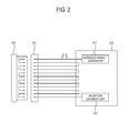
- FIG. 2 illustrates the configuration for a self diagnosis execution for a HDMI according to an exemplary embodiment.
- FIG. 3 illustrates the configuration for a self diagnosis execution for a USB interface according to other exemplary embodiment.
- FIG. 4 illustrates the configuration for a self diagnosis execution for a video circuit according to another exemplary embodiment.
- FIG. 5 illustrates a flow chart of a self diagnosis method of an electronic device.
- FIG. 6 illustrates the instruction screen for self diagnosis.
- FIG. 7 illustrates the result screen for the self diagnosis.
- FIG. 8 illustrates the configuration screen for setting the period of self diagnosis.
- an electronic device means an electronic product which has a plurality of components. Exemplary embodiments will be described in detail with reference to accompanying drawings so as to be easily realized by a person having ordinary skill in the art. The exemplary embodiments may be embodied in various forms without being limited to the exemplary embodiments set forth herein. Descriptions of well-known parts are omitted for clarity, and like reference numerals refer to like elements throughout.
- FIG. 1 illustrates an electronic device having a self diagnosis function according to an exemplary embodiment.
- FIG. 1 shows an interface 100 which receives the signal of a user's selection about the hardware of the object to be diagnosed, and a controller 200 which provides a plurality of lines connected to the hardware of the object to be diagnosed with the signal for diagnosis according to a selection signal which is received through the interface 100 , and calculates a diagnosis result according to a comparison result obtained by comparing the signal for diagnosis with a return signal which is returned from the hardware of the object to be diagnosed 300 by a loop-back operation.
- the diagnosis result for the hardware of the object to be diagnosed may be represented as whether at least a line connected to the hardware of the object to be diagnosed is cut off or disconnected, or whether different or adjacent channels have short-circuited each other.
- a display may be added to the electronic device according to an exemplary embodiment in order to receive a control signal from the controller 200 and display the diagnosis result.
- the diagnosis result may be displayed in a manner that is recognizable by a user.
- the diagnosis result may be displayed as a text which has a 7-segment shape or variable forms through the display.
- the diagnosis result may also be expressed as a sound output including an error sound, etc. Therefore a display is a preferable but not a necessary component.
- FIG. 2 illustrates an electronic device for a self diagnosis operation using HDMI according to an exemplary embodiment.
- a controller 210 may include a diagnosis signal generator 211 and a reception and judgment unit 212 . Since the controller 210 is a semiconductor chip, the diagnosis signal generator 211 and the reception and judgment unit 212 may not be hardware components but may be implemented as logic algorithm.
- the signal transmitted from the diagnosis signal generator 211 is transmitted to a HDMI 310 , formed as a loop-back by a cap 410 applying an electric current.
- the controller 210 inspects the hardware of the object to be diagnosed by forming several or a plurality of loops for inspection of a short-circuit or a disconnection between adjacent components.
- the controller 210 may permit different signals according to adjacent components for inspection of a short-circuit or a disconnection between adjacent components.
- the reception and judgment unit 212 receives a return signal and compares the received return signal to a signal generated from the diagnosis signal generator 211 , and judges an abnormality of the HDMI 310 according to a comparison result.
- the controller 210 is able to inspect whole ports by the loop-back operation not in consecutive order, but simultaneously.
- FIG. 3 illustrates an electronic device for a self diagnosis using a USB interface according to another exemplary embodiment.
- a first port 225 (Port1) among a plurality of ports (Port1, Port2, Port3, and Port4,) is inspected.
- the ports are formed at a USB hub 220 , which executes a control function.
- a signal generated from a diagnosis signal generator 222 is transmitted to the port 225 after passing by a routing logic and port controller 224 .
- This signal may be 1 byte, and is saved in a memory 221 .
- This signal is outputted through a D+ terminal of the port 225 , and is inputted to a D ⁇ terminal of the port 225 through a cap 320 applying an electric current.
- the cap 320 applying an electric current may form a loop-back circuit.
- a digital logic unit 223 judges an abnormality of the port 225 by comparing a signal which is received through the D ⁇ terminal and passed by the routing logic and port controller 224 , to a signal saved in the memory 221 .
- FIG. 4 illustrates an electronic device for a self diagnosis of a video circuit according to another exemplary embodiment.
- an impedance matching is used through 100 ⁇ resistor generally between a video main board 230 executing a control function and a video output board 330 .
- a controller 210 may execute a self diagnosis using a resistor for an impedance matching, without using an external device, by applying an internal DC power supply.
- the main board 230 of the controller 210 outputs a DC power supply through an Even1+ terminal of the main board 230 and determines a short-circuit or a disconnection by discriminating a voltage at an Even1 ⁇ terminal of the main board 230 returned by a loop-back through a 100 ⁇ resistor for an impedance matching of the video output board 330 .
- the controller 210 may discriminate each line and a short-circuit between different or adjacent channels by outputting different voltages to an Even2+ terminal and an Even3+ terminal. Then, different frequencies may be used according to each channel. In other words, the controller 210 may check a disconnection of each of the lines and a short-circuit between adjacent channels by transmitting different DC voltages or different frequencies to each of the lines.
- FIG. 5 shows a flow chart of a self diagnosis method of an electronic device.
- a manipulation for executing a self diagnosis function is inputted by a user, the input is transmitted to a controller 200 through an interface 100 .
- a user who uses a display apparatus such as a television (TV) or a monitor, may select a function for self diagnosis using a menu button provided in the display apparatus or a remote controller (operation S 301 ).
- the controller 200 may display a guide screen for a self diagnosis operation on a display apparatus, for example, with on screen display (OSD) as shown in FIG. 6 .
- the controller 200 may display a list of hardware which performs a self diagnosis function.
- a connector connects an external apparatus to the display apparatus.
- the connector may be displayed on the display apparatus as a component terminal for a signal from an external component, an audio/video input and output terminal, a high definition multimedia interface (HDMI) terminal, a universal serial bus (USB) terminal to exchange an own signal for a signal of an external apparatus, an Ethernet terminal for connecting the Internet (operation S 302 ).
- HDMI high definition multimedia interface
- USB universal serial bus
- the controller 200 receives the selection signal about the hardware of the object to be diagnosed.
- the selection of a user may be executed by various methods. For example, the selection of a user may be executed by a remote controller or a touch panel in the case where a display apparatus has a touch screen. If the electronic device for a self diagnosis according to an exemplary embodiment is a computer, the selection of a user may be executed by a mouse or a keyboard (operation S 303 ).
- a signal of the user's selection is transmitted to the controller 200 through the interface 100 .
- the controller 200 provides a plurality of lines connected to the hardware of the object to be diagnosed with a signal for diagnosis.
- the signal for diagnosis may be a signal with a DC voltage or frequency, and may be transmitted with each different values to the plurality of lines simultaneously (operation S 304 ).
- the controller 200 receives a return signal from the hardware of the object to be diagnosed by a loop-back operation (operation S 305 ), and compares the received return signal to the provided signal for diagnosis (operation S 306 ).
- the controller 200 calculates the diagnosis result about the hardware of the object to be diagnosed (operation S 307 ), and outputs the diagnosis result as shown in FIG. 7 . Therefore, if a connector has a problem, a user may be provided with a guide explaining how the connector should be repaired (operation S 308 ).
- a user may set a period for the diagnosis. For example, a user may set the period for the diagnosis to diagnose the hardware of the object to be diagnosed automatically one time per a month when main power is applied thereto.
- the period of the diagnosis is set according to the number of usage as the case may be. Then, information of the diagnosis period may be saved in the memory.
Landscapes
- Engineering & Computer Science (AREA)
- Theoretical Computer Science (AREA)
- Physics & Mathematics (AREA)
- General Physics & Mathematics (AREA)
- General Engineering & Computer Science (AREA)
- Computer Hardware Design (AREA)
- Quality & Reliability (AREA)
- Automation & Control Theory (AREA)
- Testing, Inspecting, Measuring Of Stereoscopic Televisions And Televisions (AREA)
- Controls And Circuits For Display Device (AREA)
- Testing Of Short-Circuits, Discontinuities, Leakage, Or Incorrect Line Connections (AREA)
- Test And Diagnosis Of Digital Computers (AREA)
Abstract
Description
Claims (17)
Applications Claiming Priority (2)
| Application Number | Priority Date | Filing Date | Title |
|---|---|---|---|
| KR1020120098397A KR101953117B1 (en) | 2012-09-05 | 2012-09-05 | electronic device having a self diagnose function and a self diagnose method using the same |
| KR10-2012-0098397 | 2012-09-05 |
Publications (2)
| Publication Number | Publication Date |
|---|---|
| US20140068332A1 US20140068332A1 (en) | 2014-03-06 |
| US10037256B2 true US10037256B2 (en) | 2018-07-31 |
Family
ID=48699610
Family Applications (1)
| Application Number | Title | Priority Date | Filing Date |
|---|---|---|---|
| US14/018,615 Active 2035-08-08 US10037256B2 (en) | 2012-09-05 | 2013-09-05 | Electronic device having self diagnosis function and self diagnosis method using the same |
Country Status (4)
| Country | Link |
|---|---|
| US (1) | US10037256B2 (en) |
| EP (1) | EP2706526B1 (en) |
| KR (1) | KR101953117B1 (en) |
| CN (1) | CN103678082B (en) |
Families Citing this family (9)
| Publication number | Priority date | Publication date | Assignee | Title |
|---|---|---|---|---|
| US20160321125A1 (en) * | 2015-04-30 | 2016-11-03 | Samsung Electronics Co., Ltd. | Self-diagnosis device and device including the same |
| EP3104242A1 (en) * | 2015-06-12 | 2016-12-14 | Siemens Aktiengesellschaft | Guidance system and method for the evaluation of the communication in a technical process |
| KR102544864B1 (en) | 2016-01-15 | 2023-06-19 | 삼성전자 주식회사 | Method for performing process based on result of hardware diagnose and electronic device implementing the same |
| KR20180024616A (en) * | 2016-08-30 | 2018-03-08 | 삼성전자주식회사 | Display apparatus and method of excuting calibration thereof |
| KR20180067108A (en) * | 2016-12-12 | 2018-06-20 | 삼성전자주식회사 | Display apparatus presenting status of external electronic apparatus and controlling method thereof |
| KR102696902B1 (en) | 2019-09-06 | 2024-08-20 | 삼성전자주식회사 | Electronic device and method for detecting state of connection interface |
| CN110907857B (en) * | 2019-12-10 | 2022-05-13 | 上海国微思尔芯技术股份有限公司 | Automatic connector detection method based on FPGA |
| US11966288B2 (en) | 2021-02-10 | 2024-04-23 | Samsung Electronics Co., Ltd. | Electronic apparatus performing self-test using self-test application and control method thereof |
| CN113806152B (en) * | 2021-09-14 | 2024-04-19 | 合肥联宝信息技术有限公司 | Fault diagnosis card and equipment |
Citations (21)
| Publication number | Priority date | Publication date | Assignee | Title |
|---|---|---|---|---|
| US20020133649A1 (en) * | 2001-03-14 | 2002-09-19 | Ping-Ying Chu | Apparatus and method for testing of USB device |
| KR100402348B1 (en) | 2003-07-02 | 2003-10-22 | Bong Taek Kim | Automatic train protection stop device for controlling railroad using data communication |
| US20030227653A1 (en) | 2002-06-07 | 2003-12-11 | Samsung Electronics Co., Ltd., Suwon-City, Republic Of Korea | Self-diagnosis method for facsimile device and facsimile device to perform the same |
| US20050268175A1 (en) * | 2004-05-04 | 2005-12-01 | Samsung Electronics Co., Ltd. | Self-diagnosing method and apparatus using universal serial bus |
| US20060107154A1 (en) | 2004-10-29 | 2006-05-18 | Akash Bansal | Through-core self-test with multiple loopbacks |
| US20060176943A1 (en) | 2005-02-04 | 2006-08-10 | Agere Systems, Inc. | Serializer deserializer (SERDES) testing |
| US7130791B2 (en) * | 2001-02-20 | 2006-10-31 | Samsung Electronics Co., Ltd. | Computer system and OSD displaying method for the same |
| US20070079284A1 (en) * | 2005-10-04 | 2007-04-05 | Chang-Sun Kim | Method of generating a guidance route to a target menu and image processing apparatus using the same |
| US20070104111A1 (en) * | 2005-11-04 | 2007-05-10 | Intel Corporation | Internal analog loopback for a high-speed interface test |
| US20070121711A1 (en) | 2005-11-30 | 2007-05-31 | Offord Glen E | PLL with programmable jitter for loopback serdes testing and the like |
| KR20070121881A (en) | 2006-06-23 | 2007-12-28 | 이성균 | Logging terminal monitoring system |
| KR20080003404A (en) | 2005-06-28 | 2008-01-07 | 유재천 | Biodrive device and analysis method using the same |
| KR20080005224A (en) | 2005-05-06 | 2008-01-10 | 유재천 | Digital Bio Disc and Digital Bio Disc Driver Device and Method |
| US20080126001A1 (en) * | 2006-09-01 | 2008-05-29 | Murray David W | Equipment testing system and method having scaleable test line limits |
| US20080239082A1 (en) * | 2007-03-29 | 2008-10-02 | Analogix Semiconductor, Inc. | HDMI format video pattern and audio frequencies generator for field test and built-in self test |
| US20090213913A1 (en) | 2008-02-26 | 2009-08-27 | Avago Technologies Enterprise IP (Singapore) Pte. Ltd. | Internal Loop-Back Architecture For Parallel Serializer/Deserializer (SERDES) |
| US20110110412A1 (en) * | 2009-11-12 | 2011-05-12 | Samsung Electronics Co., Ltd. | Transmitter-only ic chip having external loopback test function and external loopback test method using the same |
| CN102112914A (en) | 2008-08-06 | 2011-06-29 | 夏普株式会社 | Test method of liquid crystal display device and liquid crystal display device |
| JP2011226917A (en) | 2010-04-20 | 2011-11-10 | Mitsubishi Electric Corp | Self-diagnosis device, self-diagnosis method, and electronic device with self-diagnosis function |
| US20120079330A1 (en) | 2009-07-23 | 2012-03-29 | Kabushiki Kaisha Toshiba | Test device and test method for resistive random access memory and resistive random access memory device |
| US20120191400A1 (en) * | 2011-01-20 | 2012-07-26 | Texas Instruments Incorporated | Built-in self-test methods, circuits and apparatus for concurrent test of rf modules with a dynamically configurable test structure |
-
2012
- 2012-09-05 KR KR1020120098397A patent/KR101953117B1/en not_active Expired - Fee Related
-
2013
- 2013-06-27 EP EP13174002.9A patent/EP2706526B1/en active Active
- 2013-09-05 US US14/018,615 patent/US10037256B2/en active Active
- 2013-09-05 CN CN201310399873.XA patent/CN103678082B/en active Active
Patent Citations (23)
| Publication number | Priority date | Publication date | Assignee | Title |
|---|---|---|---|---|
| US7130791B2 (en) * | 2001-02-20 | 2006-10-31 | Samsung Electronics Co., Ltd. | Computer system and OSD displaying method for the same |
| US20020133649A1 (en) * | 2001-03-14 | 2002-09-19 | Ping-Ying Chu | Apparatus and method for testing of USB device |
| US20030227653A1 (en) | 2002-06-07 | 2003-12-11 | Samsung Electronics Co., Ltd., Suwon-City, Republic Of Korea | Self-diagnosis method for facsimile device and facsimile device to perform the same |
| CN1466370A (en) | 2002-06-07 | 2004-01-07 | ���ǵ�����ʽ���� | Facsimile device self-diagnosis method and facsimile device for performing the method |
| KR100402348B1 (en) | 2003-07-02 | 2003-10-22 | Bong Taek Kim | Automatic train protection stop device for controlling railroad using data communication |
| US20050268175A1 (en) * | 2004-05-04 | 2005-12-01 | Samsung Electronics Co., Ltd. | Self-diagnosing method and apparatus using universal serial bus |
| US20060107154A1 (en) | 2004-10-29 | 2006-05-18 | Akash Bansal | Through-core self-test with multiple loopbacks |
| US20060176943A1 (en) | 2005-02-04 | 2006-08-10 | Agere Systems, Inc. | Serializer deserializer (SERDES) testing |
| KR20080005224A (en) | 2005-05-06 | 2008-01-10 | 유재천 | Digital Bio Disc and Digital Bio Disc Driver Device and Method |
| KR20080003404A (en) | 2005-06-28 | 2008-01-07 | 유재천 | Biodrive device and analysis method using the same |
| US20070079284A1 (en) * | 2005-10-04 | 2007-04-05 | Chang-Sun Kim | Method of generating a guidance route to a target menu and image processing apparatus using the same |
| US20070104111A1 (en) * | 2005-11-04 | 2007-05-10 | Intel Corporation | Internal analog loopback for a high-speed interface test |
| US20070121711A1 (en) | 2005-11-30 | 2007-05-31 | Offord Glen E | PLL with programmable jitter for loopback serdes testing and the like |
| KR20070121881A (en) | 2006-06-23 | 2007-12-28 | 이성균 | Logging terminal monitoring system |
| US20080126001A1 (en) * | 2006-09-01 | 2008-05-29 | Murray David W | Equipment testing system and method having scaleable test line limits |
| US20080239082A1 (en) * | 2007-03-29 | 2008-10-02 | Analogix Semiconductor, Inc. | HDMI format video pattern and audio frequencies generator for field test and built-in self test |
| US20090213913A1 (en) | 2008-02-26 | 2009-08-27 | Avago Technologies Enterprise IP (Singapore) Pte. Ltd. | Internal Loop-Back Architecture For Parallel Serializer/Deserializer (SERDES) |
| CN102112914A (en) | 2008-08-06 | 2011-06-29 | 夏普株式会社 | Test method of liquid crystal display device and liquid crystal display device |
| US20110175800A1 (en) * | 2008-08-06 | 2011-07-21 | Sharp Kabushiki Kaisha | Method for testing liquid crystal display device and liquid crystal display device |
| US20120079330A1 (en) | 2009-07-23 | 2012-03-29 | Kabushiki Kaisha Toshiba | Test device and test method for resistive random access memory and resistive random access memory device |
| US20110110412A1 (en) * | 2009-11-12 | 2011-05-12 | Samsung Electronics Co., Ltd. | Transmitter-only ic chip having external loopback test function and external loopback test method using the same |
| JP2011226917A (en) | 2010-04-20 | 2011-11-10 | Mitsubishi Electric Corp | Self-diagnosis device, self-diagnosis method, and electronic device with self-diagnosis function |
| US20120191400A1 (en) * | 2011-01-20 | 2012-07-26 | Texas Instruments Incorporated | Built-in self-test methods, circuits and apparatus for concurrent test of rf modules with a dynamically configurable test structure |
Non-Patent Citations (5)
| Title |
|---|
| Communication dated Apr. 14, 2017, issued by the State Intellectual Property Office of People's Republic of China in counterpart Chinese Patent Application No. 201310399873.X. |
| Communication dated Jun. 20, 2017, issued by the European Patent Office in counterpart European Patent Application No. 13174002.9. |
| Communication dated Sep. 9, 2016, from the State Intellectual Property Office of People's Republic of China in counterpart Application No. 201310399873.X. |
| Communication from the European Patent Office issued Dec. 5, 2013 in a counterpart European Application No. 13174002.9. |
| Communication issued May 14, 2018, issued by the Korean Intellectual Property Office in counterpart Korean Patent Application No. Oct. 2012-0098397 Y. |
Also Published As
| Publication number | Publication date |
|---|---|
| KR101953117B1 (en) | 2019-05-22 |
| CN103678082A (en) | 2014-03-26 |
| EP2706526B1 (en) | 2021-08-25 |
| US20140068332A1 (en) | 2014-03-06 |
| CN103678082B (en) | 2017-10-03 |
| EP2706526A1 (en) | 2014-03-12 |
| KR20140031723A (en) | 2014-03-13 |
Similar Documents
| Publication | Publication Date | Title |
|---|---|---|
| US10037256B2 (en) | Electronic device having self diagnosis function and self diagnosis method using the same | |
| US9565427B1 (en) | High definition multimedia interface test system | |
| US9222964B2 (en) | Cable detection in a pin constrained connector | |
| CN105676109B (en) | A kind of motherboard test method and equipment | |
| TWI538524B (en) | Parallel multiplex test system and method | |
| US20130147967A1 (en) | Testing method and testing apparatus for tv system | |
| EP2708905A2 (en) | Electronic apparatus and method of testing a connector | |
| US8631168B2 (en) | Input selection mechanism for a display device | |
| KR20130068354A (en) | Channel switching device, impedance measuring system, and controlling method thereof | |
| CN102100079A (en) | Video processing device | |
| US20130046498A1 (en) | Multi-testing procedure management method and system | |
| KR20140005466A (en) | Method and device for image testing of the display panel | |
| WO2020173130A1 (en) | Connection device for integrated cable harness for diesel generator | |
| EP3373147A1 (en) | A universal platform for testing of a plurality of electronic devices and a method therefor | |
| CN101074976B (en) | Method and apparatus for inspecting connection status between display device and peripheral equipment | |
| TW201547150A (en) | Artificial mains network | |
| JP2016189164A (en) | Electronic apparatus and display device | |
| CN104243968A (en) | Testing device and high-definition digital multimedia interface function testing method | |
| KR200458112Y1 (en) | Diagnostic Jig for Multimedia Display | |
| EP3457284A1 (en) | Technique for testing an electronic device | |
| CN105847955B (en) | A kind of switching method and electronic equipment of signal source | |
| CN107423168A (en) | Method of testing and test device | |
| CN104539940A (en) | Display signal test fixture and test method | |
| US20150309909A1 (en) | Electronic device and fault analysing method | |
| CN110033788B (en) | Sound detection method, device and system of display equipment |
Legal Events
| Date | Code | Title | Description |
|---|---|---|---|
| AS | Assignment |
Owner name: SAMSUNG ELECTRONICS CO., LTD., KOREA, REPUBLIC OF Free format text: ASSIGNMENT OF ASSIGNORS INTEREST;ASSIGNORS:CHOI, YOUNG-HUN;KIM, HYUN-HO;LEE, SANG-EUN;AND OTHERS;REEL/FRAME:031145/0593 Effective date: 20130821 |
|
| STCF | Information on status: patent grant |
Free format text: PATENTED CASE |
|
| MAFP | Maintenance fee payment |
Free format text: PAYMENT OF MAINTENANCE FEE, 4TH YEAR, LARGE ENTITY (ORIGINAL EVENT CODE: M1551); ENTITY STATUS OF PATENT OWNER: LARGE ENTITY Year of fee payment: 4 |
|
| MAFP | Maintenance fee payment |
Free format text: PAYMENT OF MAINTENANCE FEE, 8TH YEAR, LARGE ENTITY (ORIGINAL EVENT CODE: M1552); ENTITY STATUS OF PATENT OWNER: LARGE ENTITY Year of fee payment: 8 |