US10034422B2 - Cutting head for a string trimmer - Google Patents

Cutting head for a string trimmer Download PDF

Info

Publication number
US10034422B2
US10034422B2 US15/182,028 US201615182028A US10034422B2 US 10034422 B2 US10034422 B2 US 10034422B2 US 201615182028 A US201615182028 A US 201615182028A US 10034422 B2 US10034422 B2 US 10034422B2
Authority
US
United States
Prior art keywords
spool
lever
string trimmer
retracted
peg
Prior art date
Legal status (The legal status is an assumption and is not a legal conclusion. Google has not performed a legal analysis and makes no representation as to the accuracy of the status listed.)
Active, expires
Application number
US15/182,028
Other versions
US20170354090A1 (en
Inventor
John Palermo
Current Assignee (The listed assignees may be inaccurate. Google has not performed a legal analysis and makes no representation or warranty as to the accuracy of the list.)
Black and Decker Inc
Original Assignee
Black and Decker Inc
Priority date (The priority date is an assumption and is not a legal conclusion. Google has not performed a legal analysis and makes no representation as to the accuracy of the date listed.)
Filing date
Publication date
Application filed by Black and Decker Inc filed Critical Black and Decker Inc
Priority to US15/182,028 priority Critical patent/US10034422B2/en
Assigned to BLACK & DECKER INC. reassignment BLACK & DECKER INC. ASSIGNMENT OF ASSIGNORS INTEREST (SEE DOCUMENT FOR DETAILS). Assignors: PALERMO, JOHN
Priority to EP17172880.1A priority patent/EP3257350B1/en
Priority to CN201720694938.7U priority patent/CN207604209U/en
Publication of US20170354090A1 publication Critical patent/US20170354090A1/en
Application granted granted Critical
Publication of US10034422B2 publication Critical patent/US10034422B2/en
Active legal-status Critical Current
Adjusted expiration legal-status Critical

Links

Images

Classifications

    • AHUMAN NECESSITIES
    • A01AGRICULTURE; FORESTRY; ANIMAL HUSBANDRY; HUNTING; TRAPPING; FISHING
    • A01DHARVESTING; MOWING
    • A01D34/00Mowers; Mowing apparatus of harvesters
    • A01D34/01Mowers; Mowing apparatus of harvesters characterised by features relating to the type of cutting apparatus
    • A01D34/412Mowers; Mowing apparatus of harvesters characterised by features relating to the type of cutting apparatus having rotating cutters
    • A01D34/416Flexible line cutters
    • A01D34/4161Means for feeding cutter line
    • A01D34/4163Means for feeding cutter line by triggered line feedout, e.g. bump-feeding
    • AHUMAN NECESSITIES
    • A01AGRICULTURE; FORESTRY; ANIMAL HUSBANDRY; HUNTING; TRAPPING; FISHING
    • A01DHARVESTING; MOWING
    • A01D34/00Mowers; Mowing apparatus of harvesters
    • A01D34/01Mowers; Mowing apparatus of harvesters characterised by features relating to the type of cutting apparatus
    • A01D34/412Mowers; Mowing apparatus of harvesters characterised by features relating to the type of cutting apparatus having rotating cutters
    • A01D34/416Flexible line cutters
    • A01D34/4161Means for feeding cutter line
    • A01D34/4162Means for feeding cutter line automatically
    • AHUMAN NECESSITIES
    • A01AGRICULTURE; FORESTRY; ANIMAL HUSBANDRY; HUNTING; TRAPPING; FISHING
    • A01DHARVESTING; MOWING
    • A01D34/00Mowers; Mowing apparatus of harvesters
    • A01D34/01Mowers; Mowing apparatus of harvesters characterised by features relating to the type of cutting apparatus
    • A01D34/412Mowers; Mowing apparatus of harvesters characterised by features relating to the type of cutting apparatus having rotating cutters
    • A01D34/416Flexible line cutters
    • A01D34/4167Protection devices

Definitions

  • the present invention discloses a string having a cutting head with an improved line feed mechanism.
  • Automatic feed systems use a pivoting arm or something similar to balance forces within the spool to feed out line when the forces become unbalanced.
  • the cutting line extends from the spinning spool and generates a force that, over time, decreases as the line is worn down. When the line is shortened past a minimum length, the force generated by the line is below a threshold so that the pivoting arm is released, allowing the spool to feed out additional line.
  • the problem with these automatic feed systems is they are very delicate and establishing the proper balance of forces within the spool is difficult.
  • cutting line is fed out when not needed. For example, a user will often operate the string trimmer close to a fence or wall, and this wears down cutting line very quickly.
  • the present invention is directed to a string trimmer having a user actuated button that feeds out line only when needed.
  • the user actuated button activates a motor braking mechanism that rapidly halts rotation of the motor, which in turn generates a large force within the spool assembly to initiate the line feed.
  • a lever within the spool assembly locks the spool relative to a spool housing. In normal operation, this lever remains locked and absorbs the forces normally associated with typical use. However, the large force generated by braking the motor unlocks the lever, allowing cutting line to be fed out. In this way, only when the user desires more line and actuates the button, is additional cutting line fed out.
  • FIG. 1 is a string trimmer in accordance with an embodiment of this invention
  • FIG. 2 is an exploded view of the working head of the string trimmer of FIG. 1 ;
  • FIG. 3 is a side cut-away view of the working head
  • FIG. 4 is top view of the spool assembly showing a retracted position
  • FIG. 5 is a top view of the spool assembly showing an extended position
  • FIG. 6 is an perspective view of the bottom of a spool
  • FIG. 7 is a cut-away view of the spool and lever in the retracted position
  • FIG. 8 is a cut-away view of the spool and lever in the extended position
  • FIG. 9 is a cut-away view of the spool and lever in a transitional position
  • FIG. 10 is a bottom view of the lever
  • FIG. 11 is a top view of the spool cap
  • FIG. 12 shows the lever peg interacting with the spool cap
  • FIGS. 13A and 13B shows a lever and spool cap according to a second embodiment of the invention
  • FIG. 14A and 14B shows the lever and spool cap according to a third embodiment of the invention
  • FIG. 1 shows a string trimmer 10 in accordance with an embodiment of the invention.
  • the string trimmer includes a shaft 12 having a working head 14 on a first forward end, and a handle 16 on a second rearward end.
  • a battery housing 18 for holding a battery to power a motor.
  • AC power may be used as well and still fall within the scope of the invention.
  • the handle 16 includes a trigger 20 to actuate the motor and a button 22 to initiate the line feed, as will be further explained later.
  • the working head 14 houses the motor 15 , and includes a spool assembly 24 and a guard 26 to shield the user from flying debris.
  • the spool assembly 24 includes a spool housing 28 , a spool 30 housed in the spool housing, and a spool cap 32 . Also included is a lever 31 that locks and releases the spool 30 relative to the spool cap 32 to feed out cutting line.
  • the spool cap 32 includes tabs 40 that engage with corresponding apertures 42 in the spool housing 28 to lock the cap 32 to the housing 28 .
  • the spool housing 28 is fixedly connected to a drive shaft 34 that is operationally connected to the output shaft 38 of the motor 15 through gears 38 . Therefore, the spool housing 28 rotates with the motor 15 .
  • the cap 32 also includes an axle 29 around which the spool 30 rotates, and openings 33 allowing for spool line to be fed out of the spool assembly 24 .
  • FIGS. 4 and 5 show a top view of the cap 32 and the lever 31 .
  • the lever 31 includes a large oval shaped opening 35 to accommodate the axle 29 , and is sized to allow the lever 31 to slide from a retracted position (shown in FIG. 4 ) to an extended position (shown in FIG. 5 ).
  • a spring 44 is set against the cap 32 and urges the lever 31 into the retracted position, and when the lever 31 in the extended position, the spring is compressed.
  • the lever 31 has two triangular shaped posts 46 at opposite ends that engage troughs 50 , 51 formed within a track 48 in the bottom of the spool 30 (see FIG. 6 ). The troughs 50 , 51 retain the posts 46 and keep the spool 30 from rotating relative to the cap 32 .
  • FIG. 7 shows the position of the posts 46 when the lever 31 is in the retracted position within the troughs 50 , 51 .
  • One of the posts 46 (in this case, the one at the top) is engaged with the inner trough 51
  • the other post (the one at the bottom) is engaged with the outer trough 50 .
  • FIG. 8 shows the lever 31 in the extended position.
  • the posts 46 are in the opposite troughs so that the top post engages the outer trough 50 and the bottom post engages the inner trough 51 . Again the spool is locked and prevented from rotating to feed more line.
  • FIG. 9 the lever 31 is shown in the transition position between the retracted and extended position. It is in this position that the posts 46 are freed from both troughs 50 , 51 and the spool 30 is free to rotate.
  • the movement of the lever 31 between its retracted and extended position occurs when the motor is started and stopped.
  • the motor is stopped, and no forces are acting on the lever 31 , and the spring 44 forces the lever 31 into its retracted position.
  • centrifugal forces act on the lever 31 to force it outwardly, against the spring force, into the extended position. It stays in this position until the motor is again stopped, removing the centrifugal forces so that the lever 31 returns to its retracted position.
  • line is fed out every time the motor is started or stopped and the lever transitions between its retracted and extended position, as is known in the prior art.
  • this design produces a lot of wasted cutting line since users don't need additional cutting line every time the motor is turned on or off.
  • the present invention overcomes this deficiency by feeding additional cutting line only when the user actually needs more cutting line. This is done by providing an L-shaped slot 52 in the spool cap 32 , which cooperates with a peg 54 on the bottom of the lever 31 (see FIGS. 10 and 11 ). The slot 52 retains the lever 31 in the extended position so that it does not feed line every time the motor is started or stopped.
  • the spool cap 32 includes internal walls 32 a on both sides of the lever 31 .
  • the walls 32 a form a channel within which the lever 31 can slide up and down. Additionally, a small clearance is provided between the walls 32 a and the lever 31 so that the lever 31 can rotate about axle 29 into and out of the arm 52 b.
  • the button 22 on the string trimmer is actuated.
  • This brakes the motor 15 and the sudden stopping of the spool assembly from spinning causes the peg 54 to move to the right and be released from the arm 52 b .
  • the lever 31 can then move back into the retracted position, and consequently, feed additional cutting line.
  • the motor can be braked or shorted electronically or a mechanical brake can be applied to the spool assembly to effectuate the sudden stop.
  • An example of an electronic braking system is disclosed in U.S. Ser. No. 14/552,682, hereby incorporated by reference.
  • the dimensions of the arm 52 b are important as it needs to be deep enough to ensure that the peg 54 remains in the locked position during normal operation and withstand the typical forces that may act on the spool assembly, such as the cutting line striking objects while in use. Conversely, the arm 52 b cannot be too deep that the peg 54 cannot be released when the button 22 is actuated and the motor braked. As can be seen in FIG. 12 , the depth of the arm 52 b is about 1 ⁇ 6 of the width of the peg 54 , and in a preferred embodiment is in the range 1/10 to 1 ⁇ 2 of the peg width.
  • FIGS. 13A and 13B show an alternate embodiment of the invention.
  • a lever 60 includes posts 62 , which engage the troughs 50 , 51 in the spool 30 similar to that described in the previous embodiment.
  • a sliding pin 64 is provided at an outer end of the lever 60 , with a resiliently biased arm 66 that urges the pin 64 to the left.
  • the pin 64 When the lever 60 is in the retracted position (shown in FIG. 13A ), the pin 64 abuts a retainer 68 .
  • the pin 64 move past the retainer 68 and the arm 66 urges the pin 64 to the left where it engages the retainer 68 and prevents the lever 60 from retracting.
  • the lever 60 will remain in this locked position until a sudden stop urges the pin 64 to the right against the biasing force of the arm 66 , and releases it from the retainer 68 , allowing the lever 60 to move back to its retracted position.
  • the lever 60 does not rotate about the axle 29 , and so the spool cap includes walls 70 that contact the lever 60 , allowing only linear movement (eg. sliding up or down in FIG. 13A ).
  • FIGS. 14A and 14B show yet another embodiment of the invention.
  • the lever 80 again includes posts 82 that engage with troughs 50 , 51 in the spool 30 to lock the spool 30 from feeding cutting line.
  • the lever 80 includes a cut-out 84 that engages a locking arm 86 that pivots about a pivot point 88 .
  • the locking arm 86 includes a head 87 with a first portion 87 a that engages the cut-out 84 , and a second portion 87 b that holds a spring 90 .
  • the spring 90 urges the arm 86 to the left.
  • the lever 80 is in the retracted position (see FIG. 14A )
  • the first portion 87 a of the head contacts an outer surface of the lever 80 .
  • the lever 80 moves to the extended position (see FIG. 14B ), the first portion 87 a of the head enters the cut-out 84 to lock the lever 80 in the extended position.
  • the lever 80 stays in this locked position until a sudden stop urges the arm 86 to the right against the biasing force of the spring 90 , unlocking the lever 80 and allowing it to return to its retracted position.
  • the spool cap includes walls 70 that allow the lever 80 to slide up and down, and prevent rotation.

Landscapes

  • Life Sciences & Earth Sciences (AREA)
  • Environmental Sciences (AREA)
  • Harvester Elements (AREA)

Abstract

The present invention is directed to a string trimmer line feeding mechanism having a sliding lever that locks a spool relative to the spool housing, and only feeds additional cutting line when the user actuates a button. This brakes a motor, which generates a force acting on the spool to move the lever into an unlocked position, allowing the spool to rotate relative to the spool housing and feed additional cutting line.

Description

FIELD OF THE INVENTION
The present invention discloses a string having a cutting head with an improved line feed mechanism.
BACKGROUND OF THE INVENTION
Existing string trimmers use a flexible line spinning at high speeds to cut vegetation. The line is often made of a plastic or similar material that is gradually worn down during use. As the line shortens, additional line is released from a spool to maintain a minimal line length for proper operation.
Existing line feed mechanisms for string trimmers fall into two general categories; bump feed and automatic line feed systems. Bump feed systems require the user to bump the working head on the ground, which causes the spool to be release from a locked position so that additional line is fed. The problem with this method is that it requires the user to regularly bang the spool housing on the ground, which wears out the spool housing. Furthermore, accidental line feeding occurs when the user inadvertently bangs the string trimmer on the ground, thus feeding out line when not needed and leading to waste.
Automatic feed systems use a pivoting arm or something similar to balance forces within the spool to feed out line when the forces become unbalanced. The cutting line extends from the spinning spool and generates a force that, over time, decreases as the line is worn down. When the line is shortened past a minimum length, the force generated by the line is below a threshold so that the pivoting arm is released, allowing the spool to feed out additional line. The problem with these automatic feed systems is they are very delicate and establishing the proper balance of forces within the spool is difficult. Oftentimes, cutting line is fed out when not needed. For example, a user will often operate the string trimmer close to a fence or wall, and this wears down cutting line very quickly. Because additional line is being automatically fed, the user is unaware that the line is being worn down so quickly, which this leads to wasted line and empty spools. Conversely, when additional line is needed, oftentimes cutting line is not properly fed out. This leads to a very frustrating user experience.
BRIEF SUMMARY OF THE INVENTION
It is therefore an object of the present invention to provide a string trimmer with a line feed mechanism that does not require the user to bang the spool housing on the ground and offers a more reliable system.
Accordingly, the present invention is directed to a string trimmer having a user actuated button that feeds out line only when needed. The user actuated button activates a motor braking mechanism that rapidly halts rotation of the motor, which in turn generates a large force within the spool assembly to initiate the line feed. A lever within the spool assembly locks the spool relative to a spool housing. In normal operation, this lever remains locked and absorbs the forces normally associated with typical use. However, the large force generated by braking the motor unlocks the lever, allowing cutting line to be fed out. In this way, only when the user desires more line and actuates the button, is additional cutting line fed out.
BRIEF DESCRIPTION OF THE INVENTION
Further features and advantages of the present invention will be better understood by reference to the following description, which is given by way of example and in association with the accompanying drawings, in which:
FIG. 1 is a string trimmer in accordance with an embodiment of this invention;
FIG. 2 is an exploded view of the working head of the string trimmer of FIG. 1;
FIG. 3 is a side cut-away view of the working head;
FIG. 4 is top view of the spool assembly showing a retracted position;
FIG. 5 is a top view of the spool assembly showing an extended position;
FIG. 6 is an perspective view of the bottom of a spool;
FIG. 7 is a cut-away view of the spool and lever in the retracted position;
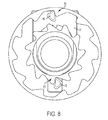
FIG. 8 is a cut-away view of the spool and lever in the extended position;
FIG. 9 is a cut-away view of the spool and lever in a transitional position;
FIG. 10 is a bottom view of the lever;
FIG. 11 is a top view of the spool cap;
FIG. 12 shows the lever peg interacting with the spool cap;
FIGS. 13A and 13B shows a lever and spool cap according to a second embodiment of the invention;
FIG. 14A and 14B shows the lever and spool cap according to a third embodiment of the invention;
DETAILED DESCRIPTION OF THE INVENTION
FIG. 1 shows a string trimmer 10 in accordance with an embodiment of the invention. The string trimmer includes a shaft 12 having a working head 14 on a first forward end, and a handle 16 on a second rearward end. To the rear of the handle 16 is a battery housing 18 for holding a battery to power a motor. It should be understood that AC power may be used as well and still fall within the scope of the invention. The handle 16 includes a trigger 20 to actuate the motor and a button 22 to initiate the line feed, as will be further explained later.
Now referring to FIGS. 2 and 3, the working head 14 houses the motor 15, and includes a spool assembly 24 and a guard 26 to shield the user from flying debris. The spool assembly 24 includes a spool housing 28, a spool 30 housed in the spool housing, and a spool cap 32. Also included is a lever 31 that locks and releases the spool 30 relative to the spool cap 32 to feed out cutting line. The spool cap 32 includes tabs 40 that engage with corresponding apertures 42 in the spool housing 28 to lock the cap 32 to the housing 28. The spool housing 28 is fixedly connected to a drive shaft 34 that is operationally connected to the output shaft 38 of the motor 15 through gears 38. Therefore, the spool housing 28 rotates with the motor 15. The cap 32 also includes an axle 29 around which the spool 30 rotates, and openings 33 allowing for spool line to be fed out of the spool assembly 24.
Now referring to FIGS. 4 and 5, the drawings show a top view of the cap 32 and the lever 31. The lever 31 includes a large oval shaped opening 35 to accommodate the axle 29, and is sized to allow the lever 31 to slide from a retracted position (shown in FIG. 4) to an extended position (shown in FIG. 5). A spring 44 is set against the cap 32 and urges the lever 31 into the retracted position, and when the lever 31 in the extended position, the spring is compressed. The lever 31 has two triangular shaped posts 46 at opposite ends that engage troughs 50, 51 formed within a track 48 in the bottom of the spool 30 (see FIG. 6). The troughs 50, 51 retain the posts 46 and keep the spool 30 from rotating relative to the cap 32.
FIG. 7 shows the position of the posts 46 when the lever 31 is in the retracted position within the troughs 50, 51. One of the posts 46 (in this case, the one at the top) is engaged with the inner trough 51, while the other post (the one at the bottom) is engaged with the outer trough 50. This prevents the spool from rotating in the counterclockwise direction, and feeding additional line out of the spool assembly. FIG. 8 shows the lever 31 in the extended position. Here, the posts 46 are in the opposite troughs so that the top post engages the outer trough 50 and the bottom post engages the inner trough 51. Again the spool is locked and prevented from rotating to feed more line. Referring now to FIG. 9, the lever 31 is shown in the transition position between the retracted and extended position. It is in this position that the posts 46 are freed from both troughs 50, 51 and the spool 30 is free to rotate.
The movement of the lever 31 between its retracted and extended position occurs when the motor is started and stopped. When the motor is stopped, and no forces are acting on the lever 31, and the spring 44 forces the lever 31 into its retracted position. When the motor is started, centrifugal forces act on the lever 31 to force it outwardly, against the spring force, into the extended position. It stays in this position until the motor is again stopped, removing the centrifugal forces so that the lever 31 returns to its retracted position. In this way, line is fed out every time the motor is started or stopped and the lever transitions between its retracted and extended position, as is known in the prior art. However, this design produces a lot of wasted cutting line since users don't need additional cutting line every time the motor is turned on or off.
The present invention overcomes this deficiency by feeding additional cutting line only when the user actually needs more cutting line. This is done by providing an L-shaped slot 52 in the spool cap 32, which cooperates with a peg 54 on the bottom of the lever 31 (see FIGS. 10 and 11). The slot 52 retains the lever 31 in the extended position so that it does not feed line every time the motor is started or stopped.
To illustrate, see FIG. 12. When the motor is stopped, the peg 54 resides at the base 52 a of the slot 52. When the motor is actuated, the spool assembly rotates in the clockwise direction (see arrow), and the lever 31 moves into the extended position due to centrifugal forces, as described previously. The peg 54 moves up from the base 52 a, and because of the rotational forces acting on the lever 31, moves into the arm 52 b of the slot 52. When the motor is de-energized and allowed to gradually reduce speed, the peg 54 engages the arm 52 b and prevents the lever 31 from returning to its retracted position. Therefore no additional cutting line is fed out when the motor is stopped. When the motor is started again, the peg 54 is already in the extended position and locked, so no line is fed out.
Referring back to FIGS. 4 and 5, the spool cap 32 includes internal walls 32 a on both sides of the lever 31. The walls 32 a form a channel within which the lever 31 can slide up and down. Additionally, a small clearance is provided between the walls 32 a and the lever 31 so that the lever 31 can rotate about axle 29 into and out of the arm 52 b.
To unlock the peg 54, the button 22 on the string trimmer is actuated. This brakes the motor 15, and the sudden stopping of the spool assembly from spinning causes the peg 54 to move to the right and be released from the arm 52 b. The lever 31 can then move back into the retracted position, and consequently, feed additional cutting line. It should be appreciated that this result can be achieved any number of ways, so long as the rotation of the spool assembly is abruptly stopped (as opposed to the gradual slowdown of the spool assembly when the user simply releases the power trigger). For example, the motor can be braked or shorted electronically or a mechanical brake can be applied to the spool assembly to effectuate the sudden stop. An example of an electronic braking system is disclosed in U.S. Ser. No. 14/552,682, hereby incorporated by reference.
Also, the dimensions of the arm 52 b are important as it needs to be deep enough to ensure that the peg 54 remains in the locked position during normal operation and withstand the typical forces that may act on the spool assembly, such as the cutting line striking objects while in use. Conversely, the arm 52 b cannot be too deep that the peg 54 cannot be released when the button 22 is actuated and the motor braked. As can be seen in FIG. 12, the depth of the arm 52 b is about ⅙ of the width of the peg 54, and in a preferred embodiment is in the range 1/10 to ½ of the peg width.
FIGS. 13A and 13B show an alternate embodiment of the invention. Here, a lever 60 includes posts 62, which engage the troughs 50, 51 in the spool 30 similar to that described in the previous embodiment. A sliding pin 64 is provided at an outer end of the lever 60, with a resiliently biased arm 66 that urges the pin 64 to the left. When the lever 60 is in the retracted position (shown in FIG. 13A), the pin 64 abuts a retainer 68. When the lever 60 is in the extended position (shown in FIG. 13B), the pin 64 move past the retainer 68 and the arm 66 urges the pin 64 to the left where it engages the retainer 68 and prevents the lever 60 from retracting. Similar to the previous embodiment, the lever 60 will remain in this locked position until a sudden stop urges the pin 64 to the right against the biasing force of the arm 66, and releases it from the retainer 68, allowing the lever 60 to move back to its retracted position. Unlike the previous embodiment, the lever 60 does not rotate about the axle 29, and so the spool cap includes walls 70 that contact the lever 60, allowing only linear movement (eg. sliding up or down in FIG. 13A).
FIGS. 14A and 14B show yet another embodiment of the invention. Here, the lever 80 again includes posts 82 that engage with troughs 50, 51 in the spool 30 to lock the spool 30 from feeding cutting line. The lever 80 includes a cut-out 84 that engages a locking arm 86 that pivots about a pivot point 88. The locking arm 86 includes a head 87 with a first portion 87 a that engages the cut-out 84, and a second portion 87 b that holds a spring 90. The spring 90 urges the arm 86 to the left. When the lever 80 is in the retracted position (see FIG. 14A), the first portion 87 a of the head contacts an outer surface of the lever 80. When the lever 80 moves to the extended position (see FIG. 14B), the first portion 87 a of the head enters the cut-out 84 to lock the lever 80 in the extended position. The lever 80 stays in this locked position until a sudden stop urges the arm 86 to the right against the biasing force of the spring 90, unlocking the lever 80 and allowing it to return to its retracted position. Like the embodiment shown in FIGS. 13A and 13B, the spool cap includes walls 70 that allow the lever 80 to slide up and down, and prevent rotation.
The foregoing description of the embodiments has been provided for purposes of illustration and description. It is not intended to be exhaustive or to limit the disclosure. Individual elements or features of a particular embodiment are generally not limited to that particular embodiment, but, where applicable, are interchangeable and can be used in a selected embodiment, even if not specifically shown or described. The same may also be varied in many ways. Such variations are not to be regarded as a departure from the disclosure, and all such modifications are intended to be included within the scope of the disclosure.

Claims (17)

The invention claimed is:
1. A method of releasing cutting line from a string trimmer comprising the steps:
providing a string trimmer having a working head including a spool assembly and a motor operatively connected to the spool assembly to rotate the spool assembly, the spool assembly having a spool housing and a spool cap that are coupled together to define an interior space, a spool having cutting line thereon and a lever housed in said interior space;
wherein the lever slides transversely between a retracted and an extended position, and in both positions, locking the spool to prevent rotation;
wherein when the motor is not energized, a spring biases the lever in one of the retracted or the extended position;
energizing the motor to rotate the spool assembly and move the lever into the other of the retracted or extended position, the lever having a peg that engages a slot in one of the spool cap or spool housing to lock the lever in the retracted or extended position, wherein the transition of the lever between the lever's retracted and extended positions unlocks the spool allowing the spool to rotate and feed out cutting line.
2. The method of releasing cutting line from a string trimmer according to claim 1, further comprising the step:
de-energizing the motor and allowing the spool assembly to gradually reduce its rotational speed at a first speed reduction rate, wherein at the first speed reduction rate the slot retains the peg and keeps the lever in the locked position so that the spool is prevented from rotating and feeding cutting line.
3. The method of releasing cutting line from a string trimmer according to claim 2, further comprising the step:
actuating a button on the string trimmer that forceably brakes the motor to reduce the motor's rotational speed at a second speed reduction rate, which is faster than the first speed reduction rate, the braking of the motor freeing the peg from the slot so that the lever moves from one of the retracted or the extended position to the other of the retracted or the extended position, and allowing the spool to rotate and feed cutting line.
4. A string trimmer tool comprising:
a shaft having a handle on one end thereof and a working head on an opposite end;
the working head including a spool assembly having a spool housing, a spool, a spool cap and a lever;
a motor operatively connected to rotate the spool assembly;
the spool housing and spool cap being coupled together to define an interior space and housing a spool with cutting line wound thereon;
the lever being movable between a retracted position and an extended position, and in both positions the lever rotationally locks the spool relative to the spool housing or spool cap, and during the transition of the lever between these two positions the spool is in an unlocked state so that the spool is free to rotate and feed out additional cutting line;
wherein the lever slides transversely, and includes a peg to lock the lever in one of the retracted or the extended position; a spring to urge the lever to one of the retracted or the extended position; and wherein one of the spool housing or spool cap includes a slot for engaging the peg to lock the lever in one of the extended or the retracted position.
5. The string trimmer tool according to claim 4, wherein the lever moves into the other extended or the retracted position from spring urged position when the spool assembly is rotating, and the lever is locked in the other extended or retracted position by the slot.
6. The string trimmer tool according to claim 5, wherein the slot is L-shaped and rotation of the spool assembly moves the peg into an arm of the slot to lock the lever in the extended or the retracted position.
7. The string trimmer tool according to claim 6, wherein the arm of the slot has a depth less than the width of the peg, to prevent the entirety of the peg from residing in the arm when locked.
8. The string trimmer tool according to claim 4, wherein the spool includes a track having troughs, and the lever includes posts that move within the track and engage the troughs when the lever is in both the extended and retracted position to lock the spool.
9. The string trimmer tool according to claim 4, wherein the lever includes an opening to accommodate an axle of the spool cap or spool housing.
10. The string trimmer tool according to claim 4, wherein one of the spool cap or spool housing includes interior walls to guide the transverse movement of the lever.
11. The string trimmer tool according to claim 9, wherein clearance space is provided between the interior walls and the lever so that the lever can rotate.
12. A string trimmer tool comprising:
a shaft having a handle on one end thereof and a working head on an opposite end;
the working head including a spool assembly having a spool housing, a spool, a spool cap and a lever;
a motor operatively connected to rotate the spool assembly;
the spool housing and spool cap being coupled together to define an interior space, the spool and lever being housed in said interior space, the spool having cutting line wound thereon;
wherein the lever slides transversely within the interior space between a retracted position and an extended position, and in both positions the lever locks the spool from rotating, and during the transition of the lever between the retracted and extended position the lever is in an unlocked state so that the spool is free to rotate to feed out additional cutting line;
wherein the lever includes a peg, and one of the spool housing or spool cap includes a slot for engaging the peg to lock the lever in one of the extended or retracted position.
13. The string trimmer tool according to claim 12, further including a spring for biasing the lever into the retracted position, wherein the lever moves into the extended position when the spool assembly is rotating, and the lever is locked in the extended position by the slot.
14. The string trimmer tool according to claim 13, wherein the slot is L-shaped and rotational forces move the peg into an arm of the slot to lock the lever in the extended position, and wherein the arm of the slot has a depth less than the width of the peg, to prevent the entirety of the peg from residing in the arm when locked.
15. The string trimmer tool according to claim 14, wherein one of the spool cap or spool housing includes interior walls confining the lever, the walls being spaced from the lever to allow the lever peg to rotate into the slot.
16. The string trimmer tool according to claim 14, wherein the spool includes a track having a series of inner troughs and outer troughs, and the lever includes at least one post that rides within the track and engages the inner and outer troughs to prevent the spool from rotating.
17. The string trimmer tool according to claim 12, wherein the lever includes an opening to accommodate an axle of the spool cap or spool housing.
US15/182,028 2016-06-14 2016-06-14 Cutting head for a string trimmer Active 2036-07-08 US10034422B2 (en)

Priority Applications (3)

Application Number Priority Date Filing Date Title
US15/182,028 US10034422B2 (en) 2016-06-14 2016-06-14 Cutting head for a string trimmer
EP17172880.1A EP3257350B1 (en) 2016-06-14 2017-05-24 Cutting head for a string trimmer
CN201720694938.7U CN207604209U (en) 2016-06-14 2017-06-14 Cutting head for cotton rope trimmer

Applications Claiming Priority (1)

Application Number Priority Date Filing Date Title
US15/182,028 US10034422B2 (en) 2016-06-14 2016-06-14 Cutting head for a string trimmer

Publications (2)

Publication Number Publication Date
US20170354090A1 US20170354090A1 (en) 2017-12-14
US10034422B2 true US10034422B2 (en) 2018-07-31

Family

ID=58772793

Family Applications (1)

Application Number Title Priority Date Filing Date
US15/182,028 Active 2036-07-08 US10034422B2 (en) 2016-06-14 2016-06-14 Cutting head for a string trimmer

Country Status (3)

Country Link
US (1) US10034422B2 (en)
EP (1) EP3257350B1 (en)
CN (1) CN207604209U (en)

Cited By (9)

* Cited by examiner, † Cited by third party
Publication number Priority date Publication date Assignee Title
US20230157205A1 (en) * 2020-04-01 2023-05-25 Husqvarna Ab Control of feed of trimmer line
US12274201B2 (en) 2020-06-19 2025-04-15 Milwaukee Electric Tool Corporation String trimmer
USD1074341S1 (en) * 2023-02-20 2025-05-13 Zhejiang Guyuehu Industry and Trade Co., Ltd. Grass trimmer
USD1074340S1 (en) * 2023-02-20 2025-05-13 Zhejiang Guyuehu Industry and Trade Co., Ltd. Grass trimmer
USD1097737S1 (en) * 2022-07-22 2025-10-14 Husqvarna Ab Trimmer
USD1101524S1 (en) * 2022-08-25 2025-11-11 Nanjing Chervon Industry Co., Ltd. String trimmer head
US12477978B2 (en) 2022-03-18 2025-11-25 Techtronic Cordless Gp Power tool and accessory mount device
US12532806B2 (en) 2023-02-14 2026-01-27 Techtronic Cordless Gp Power tool and compact power feed trimmer head
USD1111723S1 (en) * 2022-07-22 2026-02-10 Husqvarna Ab Trimmer

Families Citing this family (6)

* Cited by examiner, † Cited by third party
Publication number Priority date Publication date Assignee Title
US9924631B2 (en) 2008-04-22 2018-03-27 George E. Alliss Spool for straight through line feed vegetation trimmer apparatus with modules and spokes
USD970321S1 (en) * 2014-11-20 2022-11-22 Torvent Llc Line trimmer component
USD867833S1 (en) * 2017-10-18 2019-11-26 Changzhou Globe Co., Ltd. String trimmer head
DE102018206174A1 (en) * 2018-04-22 2019-10-24 Robert Bosch Gmbh Cutting head for a grass trimmer
USD992379S1 (en) * 2020-11-13 2023-07-18 TwoY. co. ltd. Trimmer head winding wheel
USD1048833S1 (en) * 2023-03-23 2024-10-29 Yu Du String trimmer head

Citations (37)

* Cited by examiner, † Cited by third party
Publication number Priority date Publication date Assignee Title
US4104796A (en) 1977-07-29 1978-08-08 Sheldon John D Filament-type trimmer
US4136446A (en) * 1977-01-24 1979-01-30 Weed Eater, Inc. Rotary cutting assembly with mechanical line feed
US4151646A (en) 1978-02-27 1979-05-01 K & S Industries, Inc. Flexible line trimmer with line feeding apparatus
US4209902A (en) 1977-12-19 1980-07-01 Emerson Electric Co. Apparatus for cutting vegetation
US4245454A (en) * 1979-02-12 1981-01-20 The Toro Company Line metering apparatus
US4254550A (en) 1978-08-18 1981-03-10 Kioritz Corporation Lawn trimmer
US4347666A (en) 1980-07-25 1982-09-07 Emerson Electric Co. Apparatus for cutting vegetation
US4426780A (en) * 1981-09-03 1984-01-24 The Toro Company Line metering apparatus
US4483069A (en) 1979-08-01 1984-11-20 Emerson Electric Co. Apparatus for cutting vegetation
US4607431A (en) 1983-08-24 1986-08-26 Pierre Gay Line-type foliage trimmer with automatic feed
US4651421A (en) 1985-01-31 1987-03-24 Andreas Stihl Cutterhead for a vegetation cutter
US4660286A (en) 1984-07-11 1987-04-28 Nylon Line Cutters (Pty.) Ltd. Apparatus with automatic line feeding
US4817288A (en) 1986-03-25 1989-04-04 Daijo Hirose Cutting head for cord type mower
US4835867A (en) * 1984-07-16 1989-06-06 White Consolidated Industries, Inc. Apparatus for cutting vegetation
US4852258A (en) 1981-03-19 1989-08-01 White Consolidated Industries, Inc. Apparatus for cutting vegetation
US4888871A (en) 1989-01-11 1989-12-26 Centiforce (Proprietary) Limited Driving head for line cutting devices
US4926557A (en) 1988-07-21 1990-05-22 Allegretti & Company Semi-automatic string trimmer head
US5020224A (en) 1988-07-21 1991-06-04 White Consolidated Industries, Inc. Semi-automatic string trimmer head
US5063673A (en) 1989-09-11 1991-11-12 Black & Decker Vegetation cutters
US5222301A (en) 1990-11-16 1993-06-29 Diatop Corporation Cutting head for a cord type mower
US5276968A (en) * 1978-03-30 1994-01-11 White Consolidated Industries, Inc. Apparatus for cutting vegetation
US5311665A (en) 1990-11-16 1994-05-17 Diatop Corporation Cutting head for a cord type mower
US5461787A (en) * 1994-04-07 1995-10-31 Tanaka Kogyo Co., Ltd. Filament-type trimming apparatus
EP0838144A1 (en) 1996-10-28 1998-04-29 Robert Bosch Gmbh Apparatus for cutting vegetation
US5855068A (en) 1994-03-30 1999-01-05 Robert Bosch Gmbh Apparatus for cutting of plants
US6594907B2 (en) 2000-09-05 2003-07-22 Black & Decker Inc. Cutting head for a string trimmer
US6952877B2 (en) 2003-01-10 2005-10-11 Shindaiwa, Inc. Vegetation cutting device
US7624559B2 (en) * 2006-01-10 2009-12-01 Viv Engineering Inc. Anti-wrapping trimmer with idle mow ball
US20120066913A1 (en) 2010-09-20 2012-03-22 Alliss George E Trimmer Head with Automatic Trimmer Line Feed Mechanism
CN103828535A (en) 2012-11-21 2014-06-04 苏州宝时得电动工具有限公司 Grass trimmer
CN203934334U (en) 2014-05-16 2014-11-12 苏州宝时得电动工具有限公司 Mower
CN104170579A (en) 2013-05-20 2014-12-03 苏州宝时得电动工具有限公司 Grass trimmer
CN204069756U (en) 2014-05-08 2015-01-07 苏州宝时得电动工具有限公司 Mower
CN104620756A (en) 2013-11-06 2015-05-20 苏州宝时得电动工具有限公司 Grass trimmer
US20160143218A1 (en) * 2014-11-25 2016-05-26 Black & Decker Inc. Line feed mechanism for string trimmer
US20160249529A1 (en) * 2014-05-16 2016-09-01 Positec Power Tools (Suzhou) Co., Ltd. Grass trimmer and cord delivering method of grass trimmer
WO2017059917A1 (en) 2015-10-08 2017-04-13 Husqvarna Ab Automatic line feed for trimmer

Family Cites Families (1)

* Cited by examiner, † Cited by third party
Publication number Priority date Publication date Assignee Title
DE202015009245U1 (en) * 2014-05-16 2017-02-23 Positec Power Tools (Suzhou) Co., Ltd grass trimmer

Patent Citations (42)

* Cited by examiner, † Cited by third party
Publication number Priority date Publication date Assignee Title
US4136446A (en) * 1977-01-24 1979-01-30 Weed Eater, Inc. Rotary cutting assembly with mechanical line feed
US4104796A (en) 1977-07-29 1978-08-08 Sheldon John D Filament-type trimmer
US4209902A (en) 1977-12-19 1980-07-01 Emerson Electric Co. Apparatus for cutting vegetation
US4151646A (en) 1978-02-27 1979-05-01 K & S Industries, Inc. Flexible line trimmer with line feeding apparatus
US5276968A (en) * 1978-03-30 1994-01-11 White Consolidated Industries, Inc. Apparatus for cutting vegetation
US4254550A (en) 1978-08-18 1981-03-10 Kioritz Corporation Lawn trimmer
US4245454A (en) * 1979-02-12 1981-01-20 The Toro Company Line metering apparatus
US4483069A (en) 1979-08-01 1984-11-20 Emerson Electric Co. Apparatus for cutting vegetation
US4347666A (en) 1980-07-25 1982-09-07 Emerson Electric Co. Apparatus for cutting vegetation
US4852258A (en) 1981-03-19 1989-08-01 White Consolidated Industries, Inc. Apparatus for cutting vegetation
US4426780A (en) * 1981-09-03 1984-01-24 The Toro Company Line metering apparatus
US4607431A (en) 1983-08-24 1986-08-26 Pierre Gay Line-type foliage trimmer with automatic feed
US4660286A (en) 1984-07-11 1987-04-28 Nylon Line Cutters (Pty.) Ltd. Apparatus with automatic line feeding
US4835867A (en) * 1984-07-16 1989-06-06 White Consolidated Industries, Inc. Apparatus for cutting vegetation
US4651421A (en) 1985-01-31 1987-03-24 Andreas Stihl Cutterhead for a vegetation cutter
US4817288A (en) 1986-03-25 1989-04-04 Daijo Hirose Cutting head for cord type mower
US4926557A (en) 1988-07-21 1990-05-22 Allegretti & Company Semi-automatic string trimmer head
US5020224A (en) 1988-07-21 1991-06-04 White Consolidated Industries, Inc. Semi-automatic string trimmer head
US4888871A (en) 1989-01-11 1989-12-26 Centiforce (Proprietary) Limited Driving head for line cutting devices
US5063673A (en) 1989-09-11 1991-11-12 Black & Decker Vegetation cutters
US5526572A (en) 1990-11-16 1996-06-18 Diatop Corporation Cutting head for a cord type mower
US5293692A (en) 1990-11-16 1994-03-15 Diatop Corporation Cutting head for a cord type mower
US5295306A (en) 1990-11-16 1994-03-22 Diatop Corporation Cutting head for a cord type mower
US5311665A (en) 1990-11-16 1994-05-17 Diatop Corporation Cutting head for a cord type mower
US5522141A (en) 1990-11-16 1996-06-04 Diatop Corporation Cutting head for a cord type mower
US5522140A (en) 1990-11-16 1996-06-04 Diatop Corporation Cutting head for a cord type mower
US5222301A (en) 1990-11-16 1993-06-29 Diatop Corporation Cutting head for a cord type mower
US5855068A (en) 1994-03-30 1999-01-05 Robert Bosch Gmbh Apparatus for cutting of plants
US5461787A (en) * 1994-04-07 1995-10-31 Tanaka Kogyo Co., Ltd. Filament-type trimming apparatus
EP0838144A1 (en) 1996-10-28 1998-04-29 Robert Bosch Gmbh Apparatus for cutting vegetation
US6594907B2 (en) 2000-09-05 2003-07-22 Black & Decker Inc. Cutting head for a string trimmer
US6952877B2 (en) 2003-01-10 2005-10-11 Shindaiwa, Inc. Vegetation cutting device
US7624559B2 (en) * 2006-01-10 2009-12-01 Viv Engineering Inc. Anti-wrapping trimmer with idle mow ball
US20120066913A1 (en) 2010-09-20 2012-03-22 Alliss George E Trimmer Head with Automatic Trimmer Line Feed Mechanism
CN103828535A (en) 2012-11-21 2014-06-04 苏州宝时得电动工具有限公司 Grass trimmer
CN104170579A (en) 2013-05-20 2014-12-03 苏州宝时得电动工具有限公司 Grass trimmer
CN104620756A (en) 2013-11-06 2015-05-20 苏州宝时得电动工具有限公司 Grass trimmer
CN204069756U (en) 2014-05-08 2015-01-07 苏州宝时得电动工具有限公司 Mower
CN203934334U (en) 2014-05-16 2014-11-12 苏州宝时得电动工具有限公司 Mower
US20160249529A1 (en) * 2014-05-16 2016-09-01 Positec Power Tools (Suzhou) Co., Ltd. Grass trimmer and cord delivering method of grass trimmer
US20160143218A1 (en) * 2014-11-25 2016-05-26 Black & Decker Inc. Line feed mechanism for string trimmer
WO2017059917A1 (en) 2015-10-08 2017-04-13 Husqvarna Ab Automatic line feed for trimmer

Non-Patent Citations (1)

* Cited by examiner, † Cited by third party
Title
EP Search Report for corresponding EP Application No. 17172880.1 dated Oct. 8, 2017.

Cited By (9)

* Cited by examiner, † Cited by third party
Publication number Priority date Publication date Assignee Title
US20230157205A1 (en) * 2020-04-01 2023-05-25 Husqvarna Ab Control of feed of trimmer line
US12274201B2 (en) 2020-06-19 2025-04-15 Milwaukee Electric Tool Corporation String trimmer
US12477978B2 (en) 2022-03-18 2025-11-25 Techtronic Cordless Gp Power tool and accessory mount device
USD1097737S1 (en) * 2022-07-22 2025-10-14 Husqvarna Ab Trimmer
USD1111723S1 (en) * 2022-07-22 2026-02-10 Husqvarna Ab Trimmer
USD1101524S1 (en) * 2022-08-25 2025-11-11 Nanjing Chervon Industry Co., Ltd. String trimmer head
US12532806B2 (en) 2023-02-14 2026-01-27 Techtronic Cordless Gp Power tool and compact power feed trimmer head
USD1074341S1 (en) * 2023-02-20 2025-05-13 Zhejiang Guyuehu Industry and Trade Co., Ltd. Grass trimmer
USD1074340S1 (en) * 2023-02-20 2025-05-13 Zhejiang Guyuehu Industry and Trade Co., Ltd. Grass trimmer

Also Published As

Publication number Publication date
EP3257350B1 (en) 2020-09-23
EP3257350A1 (en) 2017-12-20
US20170354090A1 (en) 2017-12-14
CN207604209U (en) 2018-07-13

Similar Documents

Publication Publication Date Title
US10034422B2 (en) Cutting head for a string trimmer
US5765287A (en) Cutting head for nylon-cord type mowers
EP1667514B1 (en) Roll-up leash
CN1946913B (en) Rotary locking mechanism for outside vehicle door handle
US4667410A (en) Cutting head for a filament-type cutter
DE19540718A1 (en) Hand tool
US10569433B1 (en) Safety cutter
PL195978B1 (en) Trigger device for chain brake
US6308425B1 (en) Tool clamping mechanism for a power tool
EP0940233B1 (en) Clutch mechanism for a chain saw
EP4327990A1 (en) Knife with sliding gear
EP0538066A1 (en) Miter saw
JP2010119353A (en) Rotary case equipped with mechanism for delivering nylon cutter for mower
KR20160115684A (en) Dual-bearing fishing reel
US5308018A (en) Drag control structure for baitcasting reel
EP0191183B1 (en) Banding machine
EP3626311B1 (en) Fall protection device for vertical lifelines
US3036789A (en) Spinning reel
CN108901917B (en) Dog rope controller
JP4804250B2 (en) Fishing spinning reel
CN110318608B (en) Door lock device and vehicle having the same
US404555A (en) Shuttle and race mechanism for sewing-machines
JPH04360634A (en) Draw ribbon handling tool of animal
CN211248549U (en) Electric tool
US156796A (en) Improvement in hand-pieces for dental drills

Legal Events

Date Code Title Description
AS Assignment

Owner name: BLACK & DECKER INC., CONNECTICUT

Free format text: ASSIGNMENT OF ASSIGNORS INTEREST;ASSIGNOR:PALERMO, JOHN;REEL/FRAME:039073/0900

Effective date: 20160613

STCF Information on status: patent grant

Free format text: PATENTED CASE

MAFP Maintenance fee payment

Free format text: PAYMENT OF MAINTENANCE FEE, 4TH YEAR, LARGE ENTITY (ORIGINAL EVENT CODE: M1551); ENTITY STATUS OF PATENT OWNER: LARGE ENTITY

Year of fee payment: 4

MAFP Maintenance fee payment

Free format text: PAYMENT OF MAINTENANCE FEE, 8TH YEAR, LARGE ENTITY (ORIGINAL EVENT CODE: M1552); ENTITY STATUS OF PATENT OWNER: LARGE ENTITY

Year of fee payment: 8