US10029936B2 - Apparatus for forming glass with edge directors and methods - Google Patents
Apparatus for forming glass with edge directors and methods Download PDFInfo
- Publication number
- US10029936B2 US10029936B2 US14/310,665 US201414310665A US10029936B2 US 10029936 B2 US10029936 B2 US 10029936B2 US 201414310665 A US201414310665 A US 201414310665A US 10029936 B2 US10029936 B2 US 10029936B2
- Authority
- US
- United States
- Prior art keywords
- pair
- tin
- weight
- platinum
- edge director
- Prior art date
- Legal status (The legal status is an assumption and is not a legal conclusion. Google has not performed a legal analysis and makes no representation as to the accuracy of the status listed.)
- Expired - Fee Related, expires
Links
Images


Classifications
-
- C—CHEMISTRY; METALLURGY
- C03—GLASS; MINERAL OR SLAG WOOL
- C03B—MANUFACTURE, SHAPING, OR SUPPLEMENTARY PROCESSES
- C03B17/00—Forming molten glass by flowing-out, pushing-out, extruding or drawing downwardly or laterally from forming slits or by overflowing over lips
- C03B17/06—Forming glass sheets
- C03B17/064—Forming glass sheets by the overflow downdraw fusion process; Isopipes therefor
-
- C—CHEMISTRY; METALLURGY
- C03—GLASS; MINERAL OR SLAG WOOL
- C03B—MANUFACTURE, SHAPING, OR SUPPLEMENTARY PROCESSES
- C03B18/00—Shaping glass in contact with the surface of a liquid
- C03B18/02—Forming sheets
- C03B18/04—Changing or regulating the dimensions of the molten glass ribbon
- C03B18/06—Changing or regulating the dimensions of the molten glass ribbon using mechanical means, e.g. restrictor bars, edge rollers
Definitions
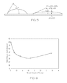
- FIG. 5 illustrates different static contact angles resulting from different sample compositions
- the edge director 111 can include a pair of upper portions 207 a , 207 b that may be joined together by a lower portion 209 . Joining the upper portions together can be beneficial to simplify assembly of the edge director 111 to the forming wedge 105 .
- the upper portions 207 a , 207 b may be provided separately.
- the edge director 111 can be separate from one another and assembled independently to each of the pair of inclined surface portions 107 a , 107 b of the forming wedge 105 . With certain configurations, providing upper portions that are not joined may simplify manufacturing of the edge directors.
- the pair of upper portions 207 a , 207 b of the edge director 111 can include a corresponding pair of first surfaces 211 a , 211 b .
- the first pair of surfaces 211 a , 211 b can each extend from a corresponding one of the pair of inclined surface portions 107 a , 107 b .
- the first surface 211 a can extend from a first inclined surface portion 107 a and the second surface 211 b can extend from the second inclined surface portion 107 b of the forming wedge 105 .
- the first pair of surfaces 211 a , 211 b can be substantially planar although the surfaces can be substantially concave and/or include other surface characteristics in further examples.
- the first pair of surfaces 211 a , 211 b are identical to one another although the surfaces may have different configurations in further examples.
- an existing edge director may be retrofitted to include the outer portion 401 .
- a platinum alloy may be provided as an outer portion 401 on an inner portion 403 comprising an existing platinum edge director.
- a coating of tin, silver and/or copper can be applied onto a standard pure platinum edge director after it is fabricated. Because wetting is a surface phenomenon, only the composition at the surface of the edge director affects the wetting of the glass surface with the molten glass.
- the coating could be applied using one of various methods, although electroplating may be particularly well suited to provide the metal coating.
- the coating could consist of pure tin, silver, copper and/or a mixture of these metals, or a mixture of one or more of these metals with platinum.
- a platinum-tin coating may be applied to a pure platinum edge director in examples of the disclosure.
- Eagle XG® glass is available from Corning, Inc., and has a glass composition of Eagle XG® glass as available from Corning, Inc. on the filing date of this application.
- the sample with the glass cylinder is placed in a furnace that is fitted with a fused silica muffle.
- the furnace is heated at a rate of 10° C./min to 1200° C. measured at the same test location in air.
- the temperature is then held at 1200° C. for 20 hours.
- images of the glass drops are acquired and the static contact angle can then be measured at the interface of the glass drops and the surface of the sample. Exact values of the contact angles may change for different glass compositions.
- features of the disclosure can be used with Alkaline Earth Boro-Aluminosilicate glasses (e.g., Eagle XG® glass) or other glass compositions.
- a surface with relatively high glass wettability can be defined as those surfaces with relatively low contact angles after conducting the testing procedure above.
- a surface with relatively low glass wettability can be defined as those surfaces with relatively high contact angles after conducting the testing procedure above.
- the first and second pair of surfaces 211 a , 211 b , 213 a , 213 b can include a relatively high glass wettability with a static contact angle of less than about 60°, such as from about 30° to about 60°, such as from about 30° to about 50°, such as from about 30° to about 40°, such as from about 30° to about 35°.
- Providing a relatively high glass wettability can be desired to enhance glass formation in accordance with aspects of the disclosure. Indeed, a relatively high glass wettability is believed to facilitate reduction of devitrification growth on the edge director, thereby, increasing the life of the edge director and improve short and long term thickness and fused edge bead quality of the glass ribbon.
- the platinum-tin alloy can include from about 0.5 weight % tin to about 2.5 weight % tin, such as from about 1 weight % tin to about 2 weight % tin, such as about 1.25 weight % tin to about 1.75 weight % tin, such as about 1.5 weight % tin.
- a method for forming glass will now be described with respect to an apparatus 101 including the example edge directors 111 . It will be appreciated that similar or identical method steps may be performed with further examples, for instance, as described throughout the application. Moreover, example methods of the present invention may omit and/or add additional steps. Unless noted, the steps can be performed simultaneously, sequentially or in different orders depending on the particular application.
- FIGS. 1 and 2 methods of forming glass with the example apparatus 101 including the edge directors 111 as schematically illustrated.
- FIG. 2 illustrates example methods being performed with the first edge director 111 located at the first end 109 a of the forming wedge 105 .
- FIG. 2 is also representative of a cross section taken at the opposite direction illustrated in FIG. 1 .
- FIG. 2 also represents example methods being performed with the second edge director 111 located at the second end 109 b.
- the method can include the step of providing the forming wedge 105 including the pair of inclined surface portions 107 a , 107 b extending between the opposed ends 109 a , 109 b of the forming wedge 105 and converging along the downstream direction 201 to form the root 203 .
- the draw plane 205 extends through the root 203 .
- each edge director 111 includes the outer portion 301 , 401 defining the first pair of surfaces 211 a , 211 b and the second pair of surfaces 213 a , 213 b .
- the first pair of surfaces 211 a , 211 b each extends from the corresponding one of the pair of inclined surface portions 107 a , 107 b of the forming wedge 105 .
- the second pair of surfaces 123 a , 213 b extends from the first pair of surfaces 211 a , 211 b and converge toward the draw plane 205 .
- the first and second pair of surfaces 211 a , 211 b , 213 a , 213 b of each edge director 111 includes a glass wettability with a static contact angle of less than about 60°, such as within a range of from about 30° to about 60°, such as from about 30° to about 50°, such as from about 30° to about 40°, such as from about 30° to about 35°.
- the platinum-tin alloy can include from about 0.5 weight % tin (Sn) to about 2.5 weight % tin (Sn), such as from about 1 weight % tin (Sn) to about 2 weight % tin (Sn), such as about 1.25 weight % tin (Sn) to about 1.75 weight % tin (Sn), such as about 1.5 weight % tin (Sn).
- the second edge director 111 also provides a representation of flowing of the second pair of lateral edges (see 125 ) of the molten glass sheets over corresponding first surfaces 211 a , 211 b of the second edge director 111 to decrease the thickness of each of the second pair of lateral edges.
- the surface area of travel increases in the downward direction, thereby stretching out the edge portions of the corresponding glass sheet to decrease the thickness of each of the pair of lateral edges.
- the method further includes the step of flowing the first pair of lateral edges 217 a , 217 b over corresponding second surfaces 213 a , 213 b of the first edge director 111 and flowing the second pair of lateral edges of the molten glass sheets over corresponding second surfaces of the second edge director, wherein the first and second pair of lateral edges each converge together toward the draw plane 205 .
- the method further includes the step of drawing the first pair of lateral edges 217 a , 217 b off the first edge director 111 and drawing the second pair of lateral edges off the second edge director.
- the first pair of lateral edges 217 a , 217 b fuse together to form a first fused edge 127 a of the glass ribbon 103 and the second pair of lateral edges fuse together to form a second fused edge 127 b of the glass ribbon 103 .
Landscapes
- Chemical & Material Sciences (AREA)
- Engineering & Computer Science (AREA)
- Materials Engineering (AREA)
- Organic Chemistry (AREA)
- Joining Of Glass To Other Materials (AREA)
- Mechanical Engineering (AREA)
Abstract
An apparatus for downwardly drawing glass ribbon comprises edge directors, wherein an outer portion defining a first pair of surfaces and a second pair of surfaces. In one example, the first and second pair of surfaces of each edge director includes a glass wettability with a static contact angle within a range of from about 30° to about 60°. In another example, the outer portion comprises a platinum alloy including from about 0.05 weight % tin to about 5 weight % tin. Methods for forming glass include the step of providing the edge director with a desired glass wettability and/or a desired platinum alloy.
Description
This is a divisional of U.S. patent application Ser. No. 13/482,336 filed on May 29, 2012, the content of which is relied upon and incorporated herein by reference in its entirety, and the benefit of priority under 35 U.S.C. §120 is hereby claimed.
The present invention relates generally to apparatus and methods for forming glass, and more particularly, to apparatus and methods for forming glass with edge directors.
It is known to manufacture glass ribbon by downwardly flowing molten glass over a forming wedge. Edge directors are frequently provided at opposed ends of the forming wedge to help maintain sheet width and minimize edge bead. There is a continued need for edge directors to control the sheet edges, for example, with high end glass compositions.
The following presents a simplified summary of the invention in order to provide a basic understanding of some example aspects of the invention. This summary is not an extensive overview of the invention. Moreover, this summary is not intended to identify critical elements of the invention nor delineate the scope of the invention. The sole purpose of the summary is to present some concepts of the invention in simplified form as a prelude to the more detailed description that is presented later.
In accordance with one aspect of the present disclosure, an apparatus for downwardly drawing glass ribbon comprises a forming wedge including a pair of inclined surface portions extending between opposed ends of the forming wedge and converging along a downstream direction to form a root. A draw plane extends through the root. The apparatus also includes an edge director positioned at each of the opposed ends. Each edge director includes an outer portion defining a first pair of surfaces and a second pair of surfaces. The first pair of surfaces each extend from a corresponding one of the pair of inclined surface portions. The second pair of surfaces extend from the first pair of surfaces and converge toward the draw plane. The first and second pair of surfaces of each edge director includes a glass wettability with a static contact angle within a range of from about 30° to about 60°, such as from about 30° to about 50°.
In another example of the aspect, at least the outer portion of each edge director comprises a platinum alloy.
In yet another example of the aspect, the platinum alloy includes a metal selected from the group consisting of tin, copper and silver.
In still another example of the aspect, the platinum alloy includes tin. For instance, the platinum-tin alloy can include less than about 5 weight % tin, such as from about 0.05 weight % tin to about 3.5 weight % tin, such as from about 0.5 weight % tin to about 2.5 weight % tin.
In accordance with another aspect of the disclosure, an apparatus for downwardly drawing glass ribbon comprises a forming wedge including a pair of inclined surface portions extending between opposed ends of the forming wedge and converging along a downstream direction to form a root. A draw plane extends through the root. The apparatus further includes an edge director positioned at each of the opposed ends. Each edge director includes an outer portion defining a first pair of surfaces and a second pair of surfaces. The first pair of surfaces each extend from a corresponding one of the pair of inclined surface portions and the second pair of surfaces extend from the first pair of surfaces and converge toward the draw plane, wherein the outer portion comprises a platinum alloy including from about 0.05 weight % tin to about 5 weight % tin.
In accordance with one example of the aspect, the platinum alloy includes from about 0.05 weight % tin to about 3.5 weight % tin, such as from about 0.5 weight % tin to about 2.5 weight % tin.
In another example of the aspect, the first and second pair of surfaces of each edge director includes a glass wettability with a static contact angle within a range of from about 30° to about 60°, such as from about 30° to about 50°.
In accordance with yet another aspect of the disclosure, a method for forming glass comprises the step of providing a forming wedge including a pair of inclined surface portions extending between opposed ends of the forming wedge and converging along a downstream direction to form a root, wherein a draw plane extends through the root. The method also includes the step of providing an edge director positioned at each of the opposed ends. Each edge director includes an outer portion defining a first pair of surfaces and a second pair of surfaces. The first pair of surfaces each extend from a corresponding one of the pair of inclined surface portions and the second pair of surfaces extend from the first pair of surfaces and converge toward the draw plane. The first and second pair of surfaces of each edge director includes a glass wettability with a static contact angle within a range of from about 30° to about 60°, such as from about 30° to about 50°. The method also includes the step of flowing a molten glass sheet over each of the pair of inclined surface portions of the forming wedge. The method further includes the step of flowing a first pair of lateral edges of the molten glass sheets over corresponding first surfaces of the first edge director and flowing a second pair of lateral edges of the molten glass sheets over corresponding first surfaces of the second edge director, wherein the thickness of each of the first and second pair of lateral edges is decreased. The method also includes the step of flowing the first pair of lateral edges over corresponding second surfaces of the first edge director and flowing the second pair of lateral edges of the molten glass sheets over corresponding second surfaces of the second edge director, wherein the first and second pair of lateral edges each converge together toward the draw plane. The method also includes the step of drawing the first pair of lateral edges off the first edge director and drawing the second pair of lateral edges off the second edge director, wherein the first pair of lateral edges fuse together to form a first fused edge of a glass ribbon and the second pair of lateral edges fuse together to form a second fused edge of the glass ribbon.
In accordance with another example of the aspect, the outer portion comprises a platinum alloy including from about 0.05 weight % tin to about 5 weight % tin, such as from about 0.05 weight % tin to about 3.5 weight % tin.
In accordance with yet another aspect of the disclosure, a method for forming glass comprises the step of providing a forming wedge including a pair of inclined surface portions extending between opposed ends of the forming wedge and converging along a downstream direction to form a root, wherein a draw plane extends through the root. The method also includes the step of providing an edge director positioned at each of the opposed ends. Each edge director includes an outer portion defining a first pair of surfaces and a second pair of surfaces. The first pair of surfaces each extend from a corresponding one of the pair of inclined surface portions and the second pair of surfaces extend from the first pair of surfaces and converge toward the draw plane. The outer portion comprises a platinum alloy including from about 0.05 weight % tin to about 5 weight % tin, such as from about 0.05 weight % tin to about 3.5 weight % tin, such as from about 0.5 weight % tin to about 2.5 weight % tin. The method also includes the step of flowing a molten glass sheet over each of the pair of inclined surface portions of the forming wedge. The method still further includes the step of flowing a first pair of lateral edges of the molten glass sheets over corresponding first surfaces of the first edge director and flowing a second pair of lateral edges of the molten glass sheets over corresponding first surfaces of the second edge director, wherein the thickness of each of the first and second pair of lateral edges is decreased. The method also includes the step of flowing the first pair of lateral edges over corresponding second surfaces of the first edge director and flowing the second pair of lateral edges of the molten glass sheets over corresponding second surfaces of the second edge director, wherein the first and second pair of lateral edges each converge together toward the draw plane. The method also includes the step of drawing the first pair of lateral edges off the first edge director and drawing the second pair of lateral edges off the second edge director, wherein the first pair of lateral edges fuse together to form a first fused edge of a glass ribbon and the second pair of lateral edges fuse together to form a second fused edge of the glass ribbon.
The foregoing and other aspects of the present invention will become apparent to those skilled in the art to which the present invention relates upon reading the following description with reference to the accompanying drawings, in which:
Example embodiments that incorporate one or more aspects of the present invention are described and illustrated in the drawings. These illustrated examples are not intended to be a limitation on the present invention. For example, one or more aspects of the present invention can be utilized in other embodiments and even other types of devices. Moreover, certain terminology is used herein for convenience only and is not to be taken as a limitation on the present invention. Still further, in the drawings, the same reference numerals are employed for designating the same elements.
Aspects of the present invention can be used with various apparatus for drawing glass ribbon. FIGS. 1 and 2 illustrate aspects of one example apparatus 101 for downwardly drawing a glass ribbon 103. The example apparatus 101 comprises a forming wedge 105 including a pair of inclined surface portions 107 a, 107 b extending between opposed ends 109 a, 109 b of the forming wedge 105. As shown in FIG. 2 , the pair of inclined surface portions 107 a, 107 b converges along a downstream direction 201 to form a root 203. A draw plane 205 extends through the root 203 wherein the glass ribbon 103 may be drawn in the downstream direction 201 along the draw plane 205. As shown, the draw plane 205 can bisect the root 203 although the draw plane 205 may extend at other orientations with respect to the root 203.
As shown in FIG. 1 , an edge director can be positioned at each of the opposed ends of the forming wedge. Indeed, a first edge director 111 can be positioned at a first end 109 a and a second identical edge director 111 can be positioned at a second end 109 b. Providing identical edge directors can be beneficial to provide a uniform glass sheet although the edge directors may have different configurations in further examples.
As shown in FIG. 2 , the edge director 111 can include a pair of upper portions 207 a, 207 b that may be joined together by a lower portion 209. Joining the upper portions together can be beneficial to simplify assembly of the edge director 111 to the forming wedge 105. In further examples, the upper portions 207 a, 207 b may be provided separately. For example, the edge director 111 can be separate from one another and assembled independently to each of the pair of inclined surface portions 107 a, 107 b of the forming wedge 105. With certain configurations, providing upper portions that are not joined may simplify manufacturing of the edge directors.
The edge directors 111 can be mounted to the forming wedge 105 by engaging an inner surface portion 208 a of the first upper portion 207 a with the first inclined surface portion 107 a of the forming wedge 105. Likewise, an inner surface portion 208 b of the second upper portion 207 b can be engaged with the second inclined surface portion 107 b of the forming wedge 105. As shown in FIG. 1 , each opposed end 109 a, 109 b can include a retaining block 115 designed to help laterally position the corresponding edge director 111 in place. For example, optional retaining blocks 115 can include a pair of planar surfaces 117 (only one shown in FIG. 1 ) that straddle the forming wedge 105. The planar surfaces 117 are designed to abut corresponding planar surfaces 119 (only one shown in FIG. 1 ) of the pair of upper portions 207 a, 207 b of the edge director 111. Once positioned, the edge directors 111 can be fastened in the position shown.
The pair of upper portions 207 a, 207 b of the edge director 111 can include a corresponding pair of first surfaces 211 a, 211 b. As shown in FIG. 2 , the first pair of surfaces 211 a, 211 b can each extend from a corresponding one of the pair of inclined surface portions 107 a, 107 b. For example, the first surface 211 a can extend from a first inclined surface portion 107 a and the second surface 211 b can extend from the second inclined surface portion 107 b of the forming wedge 105. As shown, the first pair of surfaces 211 a, 211 b can be substantially planar although the surfaces can be substantially concave and/or include other surface characteristics in further examples. Moreover, as shown, the first pair of surfaces 211 a, 211 b are identical to one another although the surfaces may have different configurations in further examples.
As shown in FIG. 1 , each of the first pair of surfaces 211 a, 211 b can include a transverse width “W” that increases in the downstream direction 201. For example, as shown, the first surfaces can have a first transverse width “W1” and a second downstream transverse width “W2” that is greater than the first transverse width “W1.” As shown, the transverse width “W” can increase in a substantially constant manner to define a linear edge 113 configured to follow the profile of the corresponding inclined surface portion of the forming wedge 105. Although not shown, the transverse width of further embodiments herein may increase in nonlinear fashion.
Referring again to FIG. 2 , the edge director 111 can further include a second pair of surfaces 213 a, 213 b extending from the first pair of surfaces 211 a, 211 b and converging toward the draw plane 205 downstream from the root 203. As shown, the second pair of surfaces 213 a, 213 b can be substantially planar although the surfaces can be substantially concave and/or include other surfaces characteristics in further examples. Moreover, as shown, the second pair of surfaces 213 a, 213 b can be substantially identical to one another although the surfaces may have different configurations in further examples.
The edge director 111 can still further include an optional downstream structure extending with respect to the second pair of surfaces 213 a, 213 b and downstream from the root 203. As shown in FIG. 1 , the downstream structure of the edge director 111 can comprise an optional blade 121 extending with respect to the second pair of surfaces 213 a, 213 b. The blade 121 can comprise a first surface 123 extending from the first surface 213 a of the second pair of surface and a second surface (not shown) extending from the second surface 213 b of the second pair of surfaces.
In one example, an existing edge director may be retrofitted to include the outer portion 401. For example, a platinum alloy may be provided as an outer portion 401 on an inner portion 403 comprising an existing platinum edge director. In such an example, a coating of tin, silver and/or copper can be applied onto a standard pure platinum edge director after it is fabricated. Because wetting is a surface phenomenon, only the composition at the surface of the edge director affects the wetting of the glass surface with the molten glass. The coating could be applied using one of various methods, although electroplating may be particularly well suited to provide the metal coating. The coating could consist of pure tin, silver, copper and/or a mixture of these metals, or a mixture of one or more of these metals with platinum. For example, a platinum-tin coating may be applied to a pure platinum edge director in examples of the disclosure.
The first pair of surfaces 211 a, 211 b and the second pair of surfaces 213 a, 213 b defined by the outer portion 301, 401 can include a glass wettability that is relatively high when compared to the surfaces of a conventional edge director. As used throughout the application, glass wettability can be defined as how easily a cylinder Eagle XG® glass spreads over a horizontal surface in accordance with the following testing procedure. The glass wettability, as used herein, can be measured by conducting an experiment where a 9 mm diameter×12 mm height glass cylinder of Eagle XG® glass is placed on a surface of a sample to be tested. Eagle XG® glass is available from Corning, Inc., and has a glass composition of Eagle XG® glass as available from Corning, Inc. on the filing date of this application. During the test, the sample with the glass cylinder is placed in a furnace that is fitted with a fused silica muffle. The furnace is heated at a rate of 10° C./min to 1200° C. measured at the same test location in air. The temperature is then held at 1200° C. for 20 hours. After holding the temperature for 20 hours, images of the glass drops are acquired and the static contact angle can then be measured at the interface of the glass drops and the surface of the sample. Exact values of the contact angles may change for different glass compositions. In some examples, features of the disclosure can be used with Alkaline Earth Boro-Aluminosilicate glasses (e.g., Eagle XG® glass) or other glass compositions.
The left side of FIG. 5 illustrates the glass wettability of a conventional surface of a conventional pure as-rolled platinum sample. As shown, the glass wettability is relatively low since the contact angle (i.e., about) 80° is relatively high. In contrast, the right side of FIG. 5 illustrates the glass wettability of a surface in accordance with aspects of the present disclosure including a platinum alloy that is likewise rolled with a similar surface roughness when compared to the surface roughness of the conventional sample on the left. As shown, the platinum alloy sample of FIG. 5 comprises a platinum alloy including 1.65 weight % tin (Sn) and the remaining weight of the sample comprising platinum (Pt). As shown, the surface of the present invention can include a relatively high wettability since the static contact angle is relatively low (i.e., about 31.5° on the right side of FIG. 5 ).
Glass wettability can be influenced by the surface roughness of the sample. It was observed, however, that the static contact angle of a surface from an as-rolled pure platinum surface was approximately the same as a 320 grit-roughened pure platinum surface having a surface roughness of about 8-10 microinches. However, the static contact angle of a sand-blasted pure platinum sample was significantly higher, indicating a reduced glass wettability. As such, aspects of the disclosure may optionally be used with surface roughnesses of less than 8-10 microinches.
As set forth above, a surface with relatively high glass wettability can be defined as those surfaces with relatively low contact angles after conducting the testing procedure above. Likewise, a surface with relatively low glass wettability can be defined as those surfaces with relatively high contact angles after conducting the testing procedure above. In some examples of the present invention, the first and second pair of surfaces 211 a, 211 b, 213 a, 213 b can include a relatively high glass wettability with a static contact angle of less than about 60°, such as from about 30° to about 60°, such as from about 30° to about 50°, such as from about 30° to about 40°, such as from about 30° to about 35°.
Providing a relatively high glass wettability can be desired to enhance glass formation in accordance with aspects of the disclosure. Indeed, a relatively high glass wettability is believed to facilitate reduction of devitrification growth on the edge director, thereby, increasing the life of the edge director and improve short and long term thickness and fused edge bead quality of the glass ribbon.
Increasing the glass wettability can be achieved, for example, by providing an edge director from a platinum alloy rather than fabricating the edge director from pure platinum. Providing a platinum alloy can increase the strength of the edge director while also increasing the glass wettability. In one example, desirable glass wettability may be achieved wherein the platinum alloy comprises a metal selected from the group consisting of tin, copper and silver. For instance, the platinum alloy can include tin. Tin may be particularly beneficial in applications where the apparatus will be downwardly drawing glass including tin within the composition of the glass. As such, tin will remain in the glass and there will be a reduced tendency of tin otherwise being drawn out of the glass into the pure platinum. In a case where pure platinum is used for the edge director, the outer surface of the pure platinum edge director in contact with the molten glass including tin in the molten glass composition may form a platinum-tin alloy at the contact surface of the edge director but in reduced quantities less than 0.01 weight percent tin and in a quantity that does not result in increased glass wettability to the point where the contact angle would be reduced to a static contact angle of 60° or less.
It is also noted that providing a platinum tin alloy was observed to result in a liquidus temperature for Eagle XG® glass at the Pt—Sn interface (˜98% Pt/2% Sn) that is comparable or lower than that of a Pt interface (100% Pt).
In some examples, at least the outer portion 301, 401 of each edge director 111 comprises a platinum-tin alloy including tin in an amount that is less than about 5 weight % tin. For example, the platinum-tin alloy can include from about 0.05 weight % tin to about 3.5 weight % tin, such as about 0.07 weight % tin to about 3.5 weight % tin, such as about 0.1 weight % tin to about 3.5 weight % tin, such as about 0.3 weight % tin to about 3.5 weight % tin. In another example, the platinum-tin alloy can include from about 0.5 weight % tin to about 2.5 weight % tin, such as from about 1 weight % tin to about 2 weight % tin, such as about 1.25 weight % tin to about 1.75 weight % tin, such as about 1.5 weight % tin.
In further examples, at least the outer portion 301, 401 of each edge director 111 may comprise a platinum alloy (e.g., including tin, copper and/or silver) in an amount such that the static contact angle is less than about 60°, such as from about 30° to about 60°, such as from about 30° to about 50°, such as from about 30° to about 40°, such as from about 30° to about 35°.
A method for forming glass will now be described with respect to an apparatus 101 including the example edge directors 111. It will be appreciated that similar or identical method steps may be performed with further examples, for instance, as described throughout the application. Moreover, example methods of the present invention may omit and/or add additional steps. Unless noted, the steps can be performed simultaneously, sequentially or in different orders depending on the particular application.
As shown in FIGS. 1 and 2 , methods of forming glass with the example apparatus 101 including the edge directors 111 as schematically illustrated. FIG. 2 illustrates example methods being performed with the first edge director 111 located at the first end 109 a of the forming wedge 105. FIG. 2 is also representative of a cross section taken at the opposite direction illustrated in FIG. 1 . Thus, FIG. 2 also represents example methods being performed with the second edge director 111 located at the second end 109 b.
The method can include the step of providing the forming wedge 105 including the pair of inclined surface portions 107 a, 107 b extending between the opposed ends 109 a, 109 b of the forming wedge 105 and converging along the downstream direction 201 to form the root 203. As shown in FIG. 2 , the draw plane 205 extends through the root 203.
The method further includes the step of providing the edge director 111 positioned at each of the opposed ends 109 a, 109 b. As discussed previously with respect to FIGS. 3 and 4 , each edge director 111 includes the outer portion 301, 401 defining the first pair of surfaces 211 a, 211 b and the second pair of surfaces 213 a, 213 b. The first pair of surfaces 211 a, 211 b each extends from the corresponding one of the pair of inclined surface portions 107 a, 107 b of the forming wedge 105. Moreover, the second pair of surfaces 123 a, 213 b extends from the first pair of surfaces 211 a, 211 b and converge toward the draw plane 205.
In one example, the first and second pair of surfaces 211 a, 211 b, 213 a, 213 b of each edge director 111 includes a glass wettability with a static contact angle of less than about 60°, such as within a range of from about 30° to about 60°, such as from about 30° to about 50°, such as from about 30° to about 40°, such as from about 30° to about 35°.
In some examples, at least the outer portion 301, 401 of each edge director 111, such as the entire edge director, can comprise a platinum alloy. In one example, the platinum alloy includes a metal selected from the group consisting of tin, copper and silver to respectively form a platinum-tin alloy, a platinum-copper alloy or a platinum-silver alloy. For instance, the platinum alloy can comprise a platinum-tin alloy including tin in an amount that is less than about 5 weight % tin (Sn). For example, the platinum-tin alloy can include from about 0.05 weight % tin (Sn) to about 3.5 weight % tin (Sn). In another example, the platinum-tin alloy can include from about 0.5 weight % tin (Sn) to about 2.5 weight % tin (Sn), such as from about 1 weight % tin (Sn) to about 2 weight % tin (Sn), such as about 1.25 weight % tin (Sn) to about 1.75 weight % tin (Sn), such as about 1.5 weight % tin (Sn).
The method can further include the step of flowing a molten glass sheet over each of the pair of inclined surface portions 107 a, 107 b of the forming wedge 105. For example, as shown in FIG. 2 , a central portion 215 a of a first molten glass sheet flows over the first inclined surface portion 107 a of the forming wedge 105. Likewise, a central portion 215 b of a second molten glass sheet flows over the second inclined surface portion 107 b of the forming wedge 105.
As shown in FIG. 2 , the method can also include the step of flowing a first pair of lateral edges 217 a, 217 b of the molten glass sheets over corresponding first surfaces 211 a, 211 b of the first edge director 111 and flowing a second pair of lateral edges of the molten glass sheets over corresponding first surfaces 211 a, 211 b of the second edge director, wherein the thickness of each of the first and second pair of lateral edges is decreased. One of a second pair of lateral edges of the molten glass sheets is referenced as 125 in FIG. 1 wherein the other of the pair of lateral edges is hidden. As the first and second edge director can be identical, it will be appreciated that FIG. 2 also provides a representation of flowing of the second pair of lateral edges (see 125) of the molten glass sheets over corresponding first surfaces 211 a, 211 b of the second edge director 111 to decrease the thickness of each of the second pair of lateral edges. As each of the first pair of surfaces 211 a, 211 b extend from a corresponding one of the pair of inclined surface portions 107 a, 107 b, the surface area of travel increases in the downward direction, thereby stretching out the edge portions of the corresponding glass sheet to decrease the thickness of each of the pair of lateral edges.
The method further includes the step of flowing the first pair of lateral edges 217 a, 217 b over corresponding second surfaces 213 a, 213 b of the first edge director 111 and flowing the second pair of lateral edges of the molten glass sheets over corresponding second surfaces of the second edge director, wherein the first and second pair of lateral edges each converge together toward the draw plane 205.
The method further includes the step of drawing the first pair of lateral edges 217 a, 217 b off the first edge director 111 and drawing the second pair of lateral edges off the second edge director. The first pair of lateral edges 217 a, 217 b fuse together to form a first fused edge 127 a of the glass ribbon 103 and the second pair of lateral edges fuse together to form a second fused edge 127 b of the glass ribbon 103.
The invention has been described with reference to the example embodiments described above. Modifications and alterations will occur to others upon a reading and understanding of this specification. Example embodiments incorporating one or more aspects of the invention are intended to include all such modifications and alterations insofar as they come within the scope of the appended claims.
Claims (19)
1. An apparatus for downwardly drawing glass ribbon comprising:
a forming wedge including a pair of inclined surface portions extending between opposed ends of the forming wedge and converging along a downstream direction to form a root, wherein a draw plane extends through the root; and
an edge director positioned at each of the opposed ends, each edge director including an outer portion defining a first pair of surfaces and a second pair of surfaces, wherein the first pair of surfaces each extend from a corresponding one of the pair of inclined surface portions, the second pair of surfaces extend from the first pair of surfaces and converge toward the draw plane, wherein the outer portion comprises a platinum-tin alloy, and wherein the first and second pair of surfaces of each edge director includes a glass wettability with a static contact angle within a range of from about 30° to about 60° for an alkaline earth boro-aluminosilicate glass.
2. The apparatus of claim 1 , wherein the range of the static contact angle is from about 30° to about 50°.
3. The apparatus of claim 2 , wherein the range of the static contact angle is from about 30° to about 40°.
4. The apparatus of claim 2 , wherein the range of the static contact angle is from about 30° to about 35°.
5. The apparatus of claim 1 , wherein the platinum-tin alloy includes less than about 5 weight % tin.
6. The apparatus of claim 5 , wherein the platinum-tin alloy includes from about 0.05 weight % tin to about 5 weight % tin.
7. The apparatus of claim 6 , wherein the range of the static contact angle is from about 30° to about 50°.
8. The apparatus of claim 6 , wherein the platinum-tin alloy includes from about 0.05 weight % tin to about 3.5 weight % tin.
9. The apparatus of claim 8 , wherein the range of the static contact angle is from about 30° to about 50°.
10. The apparatus of claim 8 , wherein the platinum-tin alloy includes from about 0.5 weight % tin to about 2.5 weight % tin.
11. The apparatus of claim 10 , wherein the range of the static contact angle is from about 30° to about 50°.
12. An apparatus for downwardly drawing glass ribbon comprising:
a forming wedge including a pair of inclined surface portions extending between opposed ends of the forming wedge and converging along a downstream direction to form a root, wherein a draw plane extends through the root; and
an edge director positioned at each of the opposed ends, each edge director including an outer portion defining a first pair of surfaces and a second pair of surfaces, wherein the first pair of surfaces each extend from a corresponding one of the pair of inclined surface portions, the second pair of surfaces extend from the first pair of surfaces and converge toward the draw plane, wherein the outer portion comprises a platinum alloy including from about 0.05 weight % tin to about 5 weight % tin.
13. The apparatus of claim 12 , wherein the platinum alloy includes from about 0.05 weight % tin to about 3.5 weight % tin.
14. The apparatus of claim 13 , wherein the platinum alloy includes from about 0.5 weight % tin to about 2.5 weight % tin.
15. An apparatus for downwardly drawing glass ribbon comprising:
a forming wedge including a pair of inclined surface portions extending between opposed ends of the forming wedge and converging along a downstream direction to form a root, wherein a draw plane extends through the root; and
an edge director positioned at each of the opposed ends, each edge director including an outer portion defining a first pair of surfaces and a second pair of surfaces, wherein the first pair of surfaces each extend from a corresponding one of the pair of inclined surface portions, the second pair of surfaces extend from the first pair of surfaces and converge toward the draw plane, wherein the outer portion comprises a platinum alloy including a metal selected from the group consisting of tin, copper and silver, and wherein the first and second pair of surfaces of each edge director includes a glass wettability with a static contact angle within a range of from about 30° to about 60° for an alkaline earth boro-aluminosilicate glass.
16. The apparatus of claim 15 , wherein the range of the static contact angle is from about 30° to about 50°.
17. The apparatus of claim 16 , wherein the range of the static contact angle is from about 30° to about 40°.
18. The apparatus of claim 17 , wherein the range of the static contact angle is from about 30° to about 35°.
19. The apparatus of claim 15 , wherein the platinum alloy includes tin.
Priority Applications (1)
| Application Number | Priority Date | Filing Date | Title |
|---|---|---|---|
| US14/310,665 US10029936B2 (en) | 2012-05-29 | 2014-06-20 | Apparatus for forming glass with edge directors and methods |
Applications Claiming Priority (2)
| Application Number | Priority Date | Filing Date | Title |
|---|---|---|---|
| US13/482,336 US8794034B2 (en) | 2012-05-29 | 2012-05-29 | Apparatus for forming glass with edge directors and methods |
| US14/310,665 US10029936B2 (en) | 2012-05-29 | 2014-06-20 | Apparatus for forming glass with edge directors and methods |
Related Parent Applications (1)
| Application Number | Title | Priority Date | Filing Date |
|---|---|---|---|
| US13/482,336 Division US8794034B2 (en) | 2012-05-29 | 2012-05-29 | Apparatus for forming glass with edge directors and methods |
Publications (2)
| Publication Number | Publication Date |
|---|---|
| US20140298861A1 US20140298861A1 (en) | 2014-10-09 |
| US10029936B2 true US10029936B2 (en) | 2018-07-24 |
Family
ID=49668619
Family Applications (2)
| Application Number | Title | Priority Date | Filing Date |
|---|---|---|---|
| US13/482,336 Expired - Fee Related US8794034B2 (en) | 2012-05-29 | 2012-05-29 | Apparatus for forming glass with edge directors and methods |
| US14/310,665 Expired - Fee Related US10029936B2 (en) | 2012-05-29 | 2014-06-20 | Apparatus for forming glass with edge directors and methods |
Family Applications Before (1)
| Application Number | Title | Priority Date | Filing Date |
|---|---|---|---|
| US13/482,336 Expired - Fee Related US8794034B2 (en) | 2012-05-29 | 2012-05-29 | Apparatus for forming glass with edge directors and methods |
Country Status (6)
| Country | Link |
|---|---|
| US (2) | US8794034B2 (en) |
| JP (1) | JP6246799B2 (en) |
| KR (1) | KR20150022908A (en) |
| CN (1) | CN104507882B (en) |
| TW (1) | TWI602789B (en) |
| WO (1) | WO2013181239A1 (en) |
Families Citing this family (15)
| Publication number | Priority date | Publication date | Assignee | Title |
|---|---|---|---|---|
| US9512025B2 (en) | 2014-05-15 | 2016-12-06 | Corning Incorporated | Methods and apparatuses for reducing heat loss from edge directors |
| US10703664B2 (en) * | 2014-09-30 | 2020-07-07 | Corning Incorporated | Isopipe with curb at the compression end and method for forming a glass ribbon |
| JP6679585B2 (en) * | 2014-10-07 | 2020-04-15 | ショット アクチエンゲゼルシャフトSchott AG | Laminated glass with increased strength |
| WO2017087585A1 (en) * | 2015-11-20 | 2017-05-26 | Corning Incorporated | Laminated glass ribbons and apparatuses for forming laminated glass ribbons |
| US9840431B2 (en) * | 2016-01-11 | 2017-12-12 | Corning Incorporated | Methods and apparatuses for supporting forming bodies of glass forming apparatuses |
| KR20190004358A (en) * | 2016-06-02 | 2019-01-11 | 코닝 인코포레이티드 | Method and apparatus comprising an edge director for forming a glass ribbon |
| KR102526393B1 (en) * | 2017-04-24 | 2023-04-28 | 코닝 인코포레이티드 | Fusion draw device and manufacturing method of glass ribbon |
| KR102490511B1 (en) * | 2017-04-28 | 2023-01-19 | 코닝 인코포레이티드 | Edge directors with internal heating |
| WO2019089525A1 (en) * | 2017-10-31 | 2019-05-09 | Corning Incorporated | Methods of manufacturing glass ribbon |
| JP7261797B2 (en) * | 2017-11-22 | 2023-04-20 | コーニング インコーポレイテッド | Apparatus with edge guide member for shaping glass ribbon |
| CN108793689B (en) * | 2018-08-01 | 2021-08-03 | 彩虹显示器件股份有限公司 | Glass substrate integration overflow shaping controlling means |
| CN111807684B (en) * | 2020-07-01 | 2023-07-07 | 彩虹显示器件股份有限公司 | Control method for forming quality stability of overflow bricks |
| WO2023177540A1 (en) * | 2022-03-16 | 2023-09-21 | Corning Incorporated | Direct heated edge director assembly |
| WO2023211746A1 (en) * | 2022-04-29 | 2023-11-02 | Corning Incorporated | Glass forming apparatus and method for forming a glass ribbon |
| JP2024039850A (en) | 2022-09-12 | 2024-03-25 | Agc株式会社 | Glass molding device |
Citations (15)
| Publication number | Priority date | Publication date | Assignee | Title |
|---|---|---|---|---|
| US2190296A (en) * | 1938-08-27 | 1940-02-13 | Westinghouse Electric & Mfg Co | Guide for molten material |
| US2234986A (en) * | 1936-10-13 | 1941-03-18 | Owens Corning Fiberglass Corp | Mechanically drawing fibers |
| US3451798A (en) * | 1966-04-04 | 1969-06-24 | Corning Glass Works | Sheet glass edge control device |
| US3537834A (en) * | 1968-08-07 | 1970-11-03 | Corning Glass Works | Maintaining sheet glass width |
| US3672880A (en) * | 1965-06-19 | 1972-06-27 | Johnson Matthew & Co Ltd | Platinum-rhodium-gold alloys |
| US4473387A (en) | 1982-10-28 | 1984-09-25 | Societe Vetrotex Saint-Gobain | Fiberizing apparatus intended for the manufacture of continuous glass fibers |
| US5017205A (en) | 1989-04-14 | 1991-05-21 | Nitto Boseki Co., Ltd. | Nozzle plate for spinning glass fibres |
| US20050183455A1 (en) | 2004-02-23 | 2005-08-25 | Pitbladdo Richard B. | Sheet width control for overflow downdraw sheet glass forming apparatus |
| KR20070108252A (en) | 2005-02-24 | 2007-11-08 | 코닝 인코포레이티드 | Method and apparatus for making a glass sheet |
| US7409839B2 (en) * | 2005-04-29 | 2008-08-12 | Corning Incorporated | Method and apparatus for making a glass sheet |
| KR20090016564A (en) | 2006-04-28 | 2009-02-16 | 코닝 인코포레이티드 | Apparatus and method for forming a glass substrate with increased edge stability |
| US20100083704A1 (en) * | 2008-10-08 | 2010-04-08 | Paul Richard Grzesik | Methods and apparatus for manufacturing glass sheet |
| US20110209502A1 (en) | 2010-02-26 | 2011-09-01 | Ahdi El Kahlout | Methods and apparatus for reducing heat loss from an edge director |
| WO2011136109A1 (en) | 2010-04-28 | 2011-11-03 | 旭硝子株式会社 | Molten glass treatment apparatus, process for production thereof, and use thereof |
| KR20110130438A (en) | 2009-02-26 | 2011-12-05 | 코닝 인코포레이티드 | Apparatus for forming glass with edge directors and methods |
Family Cites Families (2)
| Publication number | Priority date | Publication date | Assignee | Title |
|---|---|---|---|---|
| US372880A (en) * | 1887-11-08 | John keil tullis | ||
| WO2006091389A2 (en) * | 2005-02-24 | 2006-08-31 | Corning Incorporated | Apparatus and method for making a glass sheet |
-
2012
- 2012-05-29 US US13/482,336 patent/US8794034B2/en not_active Expired - Fee Related
-
2013
- 2013-05-27 TW TW102118686A patent/TWI602789B/en not_active IP Right Cessation
- 2013-05-29 CN CN201380034758.0A patent/CN104507882B/en not_active Expired - Fee Related
- 2013-05-29 KR KR20147036541A patent/KR20150022908A/en active IP Right Grant
- 2013-05-29 JP JP2015515147A patent/JP6246799B2/en not_active Expired - Fee Related
- 2013-05-29 WO PCT/US2013/043093 patent/WO2013181239A1/en active Application Filing
-
2014
- 2014-06-20 US US14/310,665 patent/US10029936B2/en not_active Expired - Fee Related
Patent Citations (16)
| Publication number | Priority date | Publication date | Assignee | Title |
|---|---|---|---|---|
| US2234986A (en) * | 1936-10-13 | 1941-03-18 | Owens Corning Fiberglass Corp | Mechanically drawing fibers |
| US2190296A (en) * | 1938-08-27 | 1940-02-13 | Westinghouse Electric & Mfg Co | Guide for molten material |
| US3672880A (en) * | 1965-06-19 | 1972-06-27 | Johnson Matthew & Co Ltd | Platinum-rhodium-gold alloys |
| US3451798A (en) * | 1966-04-04 | 1969-06-24 | Corning Glass Works | Sheet glass edge control device |
| US3537834A (en) * | 1968-08-07 | 1970-11-03 | Corning Glass Works | Maintaining sheet glass width |
| US4473387A (en) | 1982-10-28 | 1984-09-25 | Societe Vetrotex Saint-Gobain | Fiberizing apparatus intended for the manufacture of continuous glass fibers |
| US5017205A (en) | 1989-04-14 | 1991-05-21 | Nitto Boseki Co., Ltd. | Nozzle plate for spinning glass fibres |
| US20050183455A1 (en) | 2004-02-23 | 2005-08-25 | Pitbladdo Richard B. | Sheet width control for overflow downdraw sheet glass forming apparatus |
| KR20070108252A (en) | 2005-02-24 | 2007-11-08 | 코닝 인코포레이티드 | Method and apparatus for making a glass sheet |
| US7409839B2 (en) * | 2005-04-29 | 2008-08-12 | Corning Incorporated | Method and apparatus for making a glass sheet |
| US7685841B2 (en) * | 2005-04-29 | 2010-03-30 | Corning Incorporated | Method for making a glass sheet |
| KR20090016564A (en) | 2006-04-28 | 2009-02-16 | 코닝 인코포레이티드 | Apparatus and method for forming a glass substrate with increased edge stability |
| US20100083704A1 (en) * | 2008-10-08 | 2010-04-08 | Paul Richard Grzesik | Methods and apparatus for manufacturing glass sheet |
| KR20110130438A (en) | 2009-02-26 | 2011-12-05 | 코닝 인코포레이티드 | Apparatus for forming glass with edge directors and methods |
| US20110209502A1 (en) | 2010-02-26 | 2011-09-01 | Ahdi El Kahlout | Methods and apparatus for reducing heat loss from an edge director |
| WO2011136109A1 (en) | 2010-04-28 | 2011-11-03 | 旭硝子株式会社 | Molten glass treatment apparatus, process for production thereof, and use thereof |
Non-Patent Citations (7)
| Title |
|---|
| Copley, G.J., Rivers, A.D., Smith, R., "Contact angle measurements of E-Glass with platinum group metals", journal of Materials Science 10 (1975) 1285-1290. * |
| English Translation of CN201380034758.0 First Office Action dated March 23, 2016, China Office Patent. |
| English Translation of Taiwan Search Report TW102118686 dated Sep. 1, 2016, Taiwan Patent Office. |
| International Search Report and Written Opinion of the International Searching Authority; PCT/US2013/043093; dated Aug. 19, 2013. |
| L. Cao, T. P. Price, M. Weiss and D. Gao, Langmuir, 2008, 24, 1640-1643. * |
| Materials Science of Noble Metal, Edited by Li Dingxin, p. 443, South China University of Industry Press, Nov. 1991. |
| Ning, Y. Wang, Y., and Yuan, Q., "a bond parameter approach to wettability of molten glass on Pt alloy", Acta Metallurgical Sinica , vol. 17, No. 4, Aug. 1981, p. 461-466. * |
Also Published As
| Publication number | Publication date |
|---|---|
| US20130319049A1 (en) | 2013-12-05 |
| TWI602789B (en) | 2017-10-21 |
| JP2015523953A (en) | 2015-08-20 |
| JP6246799B2 (en) | 2017-12-13 |
| WO2013181239A1 (en) | 2013-12-05 |
| US8794034B2 (en) | 2014-08-05 |
| KR20150022908A (en) | 2015-03-04 |
| TW201402476A (en) | 2014-01-16 |
| US20140298861A1 (en) | 2014-10-09 |
| CN104507882B (en) | 2017-09-12 |
| CN104507882A (en) | 2015-04-08 |
Similar Documents
| Publication | Publication Date | Title |
|---|---|---|
| US10029936B2 (en) | Apparatus for forming glass with edge directors and methods | |
| CN103313945B (en) | Sheet glass manufacturing installation | |
| US10305239B2 (en) | Pane comprising an electrical connection element | |
| EP1756017B1 (en) | Isopipe mass distribution for forming glass substrates | |
| JP5898203B2 (en) | Glass plate | |
| KR102071373B1 (en) | Device for manufacturing sheet glass, and method for manufacturing sheet glass | |
| KR101464870B1 (en) | Electroconductive material for connection component | |
| DE202012013541U1 (en) | Washer with an electrical connection element | |
| CN106955892B (en) | Method for producing Fe-Ni alloy thin plate | |
| BR112013028115B1 (en) | panel with at least one electrical connection element, method for producing and using such panel | |
| KR20090028481A (en) | Sliding element and process for its production | |
| US11530153B2 (en) | Laminated glass ribbons and apparatuses for forming laminated glass ribbons | |
| US10512169B2 (en) | Glazing equipped with an electrically conductive device possessing an improved resistance to temperature cycling tests | |
| CN104736488B (en) | Sheet glass forming method and sheet glass forming device | |
| JP2014124659A (en) | Electrolytic capacitor aluminum foil and manufacturing method thereof | |
| CN109311718A (en) | It is used to form the method for glass tape and the equipment comprising edge guide | |
| KR20100029760A (en) | Isopipe sag control using improved end support conditions | |
| US20110236633A1 (en) | Apparatus for manufacturing glass plate and method of manufacturing glass plate | |
| US9580347B2 (en) | System and method for forming a glass sheet | |
| CN105683101A (en) | Tin alloy float bath, device for manufacturing float glass, method of manufacturing float glass, and float glass | |
| CN107405730B (en) | Solder and heat exchanger brazing sheet | |
| JP5882840B2 (en) | Glass composition and glass substrate for display using the same | |
| EP4197978A1 (en) | Compositions and method for preventing baggy warp defects | |
| EP2905352B1 (en) | Wire for piston rings | |
| JP5088603B2 (en) | Manufacturing method of glass substrate |
Legal Events
| Date | Code | Title | Description |
|---|---|---|---|
| STCF | Information on status: patent grant |
Free format text: PATENTED CASE |
|
| FEPP | Fee payment procedure |
Free format text: MAINTENANCE FEE REMINDER MAILED (ORIGINAL EVENT CODE: REM.); ENTITY STATUS OF PATENT OWNER: LARGE ENTITY |
|
| LAPS | Lapse for failure to pay maintenance fees |
Free format text: PATENT EXPIRED FOR FAILURE TO PAY MAINTENANCE FEES (ORIGINAL EVENT CODE: EXP.); ENTITY STATUS OF PATENT OWNER: LARGE ENTITY |
|
| STCH | Information on status: patent discontinuation |
Free format text: PATENT EXPIRED DUE TO NONPAYMENT OF MAINTENANCE FEES UNDER 37 CFR 1.362 |
|
| FP | Lapsed due to failure to pay maintenance fee |
Effective date: 20220724 |