US10029927B2 - Modular sand filtration-anchor system and wave energy water desalination system and methods of using potable water produced by wave energy desalination - Google Patents
Modular sand filtration-anchor system and wave energy water desalination system and methods of using potable water produced by wave energy desalination Download PDFInfo
- Publication number
- US10029927B2 US10029927B2 US15/023,791 US201415023791A US10029927B2 US 10029927 B2 US10029927 B2 US 10029927B2 US 201415023791 A US201415023791 A US 201415023791A US 10029927 B2 US10029927 B2 US 10029927B2
- Authority
- US
- United States
- Prior art keywords
- water
- filter
- desired application
- potable water
- application comprises
- Prior art date
- Legal status (The legal status is an assumption and is not a legal conclusion. Google has not performed a legal analysis and makes no representation as to the accuracy of the status listed.)
- Active, expires
Links
- XLYOFNOQVPJJNP-UHFFFAOYSA-N water Substances O XLYOFNOQVPJJNP-UHFFFAOYSA-N 0.000 title claims abstract description 122
- 235000012206 bottled water Nutrition 0.000 title claims abstract description 83
- 239000003651 drinking water Substances 0.000 title claims abstract description 81
- 238000000034 method Methods 0.000 title claims abstract description 55
- 238000010612 desalination reaction Methods 0.000 title claims abstract description 30
- 239000004576 sand Substances 0.000 title abstract description 28
- 150000003839 salts Chemical class 0.000 claims abstract description 57
- 238000001223 reverse osmosis Methods 0.000 claims abstract description 40
- 239000012528 membrane Substances 0.000 claims abstract description 30
- 230000009471 action Effects 0.000 claims abstract description 14
- 238000007667 floating Methods 0.000 claims abstract description 8
- 238000004519 manufacturing process Methods 0.000 claims description 16
- 230000033001 locomotion Effects 0.000 claims description 14
- 239000013505 freshwater Substances 0.000 claims description 12
- 239000012530 fluid Substances 0.000 claims description 11
- 239000000463 material Substances 0.000 claims description 10
- 238000012545 processing Methods 0.000 claims description 10
- 238000009360 aquaculture Methods 0.000 claims description 9
- 244000144974 aquaculture Species 0.000 claims description 9
- 239000002689 soil Substances 0.000 claims description 9
- 230000008878 coupling Effects 0.000 claims description 6
- 238000010168 coupling process Methods 0.000 claims description 6
- 238000005859 coupling reaction Methods 0.000 claims description 6
- 238000004378 air conditioning Methods 0.000 claims description 5
- 238000001816 cooling Methods 0.000 claims description 5
- 235000015097 nutrients Nutrition 0.000 claims description 5
- 238000004891 communication Methods 0.000 claims description 4
- 238000006243 chemical reaction Methods 0.000 abstract description 7
- 238000005067 remediation Methods 0.000 abstract description 4
- 238000004140 cleaning Methods 0.000 abstract description 3
- 230000000694 effects Effects 0.000 abstract description 2
- 230000002262 irrigation Effects 0.000 abstract description 2
- 238000003973 irrigation Methods 0.000 abstract description 2
- 238000009877 rendering Methods 0.000 abstract 1
- 239000013535 sea water Substances 0.000 description 21
- 238000010586 diagram Methods 0.000 description 12
- 238000004873 anchoring Methods 0.000 description 7
- 238000009826 distribution Methods 0.000 description 7
- 239000004746 geotextile Substances 0.000 description 7
- 230000008901 benefit Effects 0.000 description 5
- 238000005086 pumping Methods 0.000 description 5
- 238000011109 contamination Methods 0.000 description 4
- 229910000831 Steel Inorganic materials 0.000 description 3
- 230000005611 electricity Effects 0.000 description 3
- 239000004744 fabric Substances 0.000 description 3
- 230000035699 permeability Effects 0.000 description 3
- 239000010959 steel Substances 0.000 description 3
- 238000010276 construction Methods 0.000 description 2
- 235000020188 drinking water Nutrition 0.000 description 2
- 238000001914 filtration Methods 0.000 description 2
- 238000005188 flotation Methods 0.000 description 2
- 238000001802 infusion Methods 0.000 description 2
- -1 polyethylene Polymers 0.000 description 2
- 241000251468 Actinopterygii Species 0.000 description 1
- 241000785736 Pholis crassispina Species 0.000 description 1
- 239000004698 Polyethylene Substances 0.000 description 1
- HCHKCACWOHOZIP-UHFFFAOYSA-N Zinc Chemical compound [Zn] HCHKCACWOHOZIP-UHFFFAOYSA-N 0.000 description 1
- 230000003466 anti-cipated effect Effects 0.000 description 1
- 238000013459 approach Methods 0.000 description 1
- QVGXLLKOCUKJST-UHFFFAOYSA-N atomic oxygen Chemical compound [O] QVGXLLKOCUKJST-UHFFFAOYSA-N 0.000 description 1
- 239000000356 contaminant Substances 0.000 description 1
- 238000005260 corrosion Methods 0.000 description 1
- 230000007797 corrosion Effects 0.000 description 1
- 238000013016 damping Methods 0.000 description 1
- 230000002950 deficient Effects 0.000 description 1
- 238000013461 design Methods 0.000 description 1
- 238000005868 electrolysis reaction Methods 0.000 description 1
- 238000011156 evaluation Methods 0.000 description 1
- 238000011010 flushing procedure Methods 0.000 description 1
- 229920001903 high density polyethylene Polymers 0.000 description 1
- 239000004700 high-density polyethylene Substances 0.000 description 1
- 238000011065 in-situ storage Methods 0.000 description 1
- 230000007246 mechanism Effects 0.000 description 1
- 238000012986 modification Methods 0.000 description 1
- 230000004048 modification Effects 0.000 description 1
- 229910052760 oxygen Inorganic materials 0.000 description 1
- 239000001301 oxygen Substances 0.000 description 1
- 229920000573 polyethylene Polymers 0.000 description 1
- 238000011045 prefiltration Methods 0.000 description 1
- 230000008569 process Effects 0.000 description 1
- 230000004044 response Effects 0.000 description 1
- 238000009287 sand filtration Methods 0.000 description 1
- 239000004575 stone Substances 0.000 description 1
- 239000000758 substrate Substances 0.000 description 1
- 239000008400 supply water Substances 0.000 description 1
- 238000005406 washing Methods 0.000 description 1
- 239000002759 woven fabric Substances 0.000 description 1
- 239000011701 zinc Substances 0.000 description 1
- 229910052725 zinc Inorganic materials 0.000 description 1
Images


Classifications
-
- C—CHEMISTRY; METALLURGY
- C02—TREATMENT OF WATER, WASTE WATER, SEWAGE, OR SLUDGE
- C02F—TREATMENT OF WATER, WASTE WATER, SEWAGE, OR SLUDGE
- C02F1/00—Treatment of water, waste water, or sewage
- C02F1/44—Treatment of water, waste water, or sewage by dialysis, osmosis or reverse osmosis
- C02F1/441—Treatment of water, waste water, or sewage by dialysis, osmosis or reverse osmosis by reverse osmosis
-
- B—PERFORMING OPERATIONS; TRANSPORTING
- B01—PHYSICAL OR CHEMICAL PROCESSES OR APPARATUS IN GENERAL
- B01D—SEPARATION
- B01D24/00—Filters comprising loose filtering material, i.e. filtering material without any binder between the individual particles or fibres thereof
- B01D24/02—Filters comprising loose filtering material, i.e. filtering material without any binder between the individual particles or fibres thereof with the filter bed stationary during the filtration
- B01D24/04—Filters comprising loose filtering material, i.e. filtering material without any binder between the individual particles or fibres thereof with the filter bed stationary during the filtration the filtering material being clamped between pervious fixed walls
- B01D24/042—Filters comprising loose filtering material, i.e. filtering material without any binder between the individual particles or fibres thereof with the filter bed stationary during the filtration the filtering material being clamped between pervious fixed walls the filtering material being held in a flexible porous bag
-
- B—PERFORMING OPERATIONS; TRANSPORTING
- B01—PHYSICAL OR CHEMICAL PROCESSES OR APPARATUS IN GENERAL
- B01D—SEPARATION
- B01D24/00—Filters comprising loose filtering material, i.e. filtering material without any binder between the individual particles or fibres thereof
- B01D24/02—Filters comprising loose filtering material, i.e. filtering material without any binder between the individual particles or fibres thereof with the filter bed stationary during the filtration
- B01D24/10—Filters comprising loose filtering material, i.e. filtering material without any binder between the individual particles or fibres thereof with the filter bed stationary during the filtration the filtering material being held in a closed container
- B01D24/14—Downward filtration, the container having distribution or collection headers or pervious conduits
-
- B—PERFORMING OPERATIONS; TRANSPORTING
- B01—PHYSICAL OR CHEMICAL PROCESSES OR APPARATUS IN GENERAL
- B01D—SEPARATION
- B01D61/00—Processes of separation using semi-permeable membranes, e.g. dialysis, osmosis or ultrafiltration; Apparatus, accessories or auxiliary operations specially adapted therefor
- B01D61/02—Reverse osmosis; Hyperfiltration ; Nanofiltration
- B01D61/025—Reverse osmosis; Hyperfiltration
-
- B—PERFORMING OPERATIONS; TRANSPORTING
- B01—PHYSICAL OR CHEMICAL PROCESSES OR APPARATUS IN GENERAL
- B01D—SEPARATION
- B01D61/00—Processes of separation using semi-permeable membranes, e.g. dialysis, osmosis or ultrafiltration; Apparatus, accessories or auxiliary operations specially adapted therefor
- B01D61/02—Reverse osmosis; Hyperfiltration ; Nanofiltration
- B01D61/04—Feed pretreatment
-
- B—PERFORMING OPERATIONS; TRANSPORTING
- B01—PHYSICAL OR CHEMICAL PROCESSES OR APPARATUS IN GENERAL
- B01D—SEPARATION
- B01D61/00—Processes of separation using semi-permeable membranes, e.g. dialysis, osmosis or ultrafiltration; Apparatus, accessories or auxiliary operations specially adapted therefor
- B01D61/02—Reverse osmosis; Hyperfiltration ; Nanofiltration
- B01D61/06—Energy recovery
-
- B—PERFORMING OPERATIONS; TRANSPORTING
- B01—PHYSICAL OR CHEMICAL PROCESSES OR APPARATUS IN GENERAL
- B01D—SEPARATION
- B01D61/00—Processes of separation using semi-permeable membranes, e.g. dialysis, osmosis or ultrafiltration; Apparatus, accessories or auxiliary operations specially adapted therefor
- B01D61/02—Reverse osmosis; Hyperfiltration ; Nanofiltration
- B01D61/08—Apparatus therefor
-
- B—PERFORMING OPERATIONS; TRANSPORTING
- B01—PHYSICAL OR CHEMICAL PROCESSES OR APPARATUS IN GENERAL
- B01D—SEPARATION
- B01D65/00—Accessories or auxiliary operations, in general, for separation processes or apparatus using semi-permeable membranes
- B01D65/02—Membrane cleaning or sterilisation ; Membrane regeneration
-
- C—CHEMISTRY; METALLURGY
- C02—TREATMENT OF WATER, WASTE WATER, SEWAGE, OR SLUDGE
- C02F—TREATMENT OF WATER, WASTE WATER, SEWAGE, OR SLUDGE
- C02F1/00—Treatment of water, waste water, or sewage
- C02F1/001—Processes for the treatment of water whereby the filtration technique is of importance
- C02F1/004—Processes for the treatment of water whereby the filtration technique is of importance using large scale industrial sized filters
-
- E—FIXED CONSTRUCTIONS
- E02—HYDRAULIC ENGINEERING; FOUNDATIONS; SOIL SHIFTING
- E02B—HYDRAULIC ENGINEERING
- E02B9/00—Water-power plants; Layout, construction or equipment, methods of, or apparatus for, making same
- E02B9/08—Tide or wave power plants
-
- E—FIXED CONSTRUCTIONS
- E03—WATER SUPPLY; SEWERAGE
- E03B—INSTALLATIONS OR METHODS FOR OBTAINING, COLLECTING, OR DISTRIBUTING WATER
- E03B1/00—Methods or layout of installations for water supply
- E03B1/02—Methods or layout of installations for water supply for public or like main supply for industrial use
-
- F—MECHANICAL ENGINEERING; LIGHTING; HEATING; WEAPONS; BLASTING
- F03—MACHINES OR ENGINES FOR LIQUIDS; WIND, SPRING, OR WEIGHT MOTORS; PRODUCING MECHANICAL POWER OR A REACTIVE PROPULSIVE THRUST, NOT OTHERWISE PROVIDED FOR
- F03B—MACHINES OR ENGINES FOR LIQUIDS
- F03B13/00—Adaptations of machines or engines for special use; Combinations of machines or engines with driving or driven apparatus; Power stations or aggregates
- F03B13/12—Adaptations of machines or engines for special use; Combinations of machines or engines with driving or driven apparatus; Power stations or aggregates characterised by using wave or tide energy
- F03B13/14—Adaptations of machines or engines for special use; Combinations of machines or engines with driving or driven apparatus; Power stations or aggregates characterised by using wave or tide energy using wave energy
- F03B13/16—Adaptations of machines or engines for special use; Combinations of machines or engines with driving or driven apparatus; Power stations or aggregates characterised by using wave or tide energy using wave energy using the relative movement between a wave-operated member, i.e. a "wom" and another member, i.e. a reaction member or "rem"
- F03B13/20—Adaptations of machines or engines for special use; Combinations of machines or engines with driving or driven apparatus; Power stations or aggregates characterised by using wave or tide energy using wave energy using the relative movement between a wave-operated member, i.e. a "wom" and another member, i.e. a reaction member or "rem" wherein both members, i.e. wom and rem are movable relative to the sea bed or shore
-
- B—PERFORMING OPERATIONS; TRANSPORTING
- B01—PHYSICAL OR CHEMICAL PROCESSES OR APPARATUS IN GENERAL
- B01D—SEPARATION
- B01D2101/00—Types of filters having loose filtering material
- B01D2101/04—Sand or gravel filters
-
- B—PERFORMING OPERATIONS; TRANSPORTING
- B01—PHYSICAL OR CHEMICAL PROCESSES OR APPARATUS IN GENERAL
- B01D—SEPARATION
- B01D2201/00—Details relating to filtering apparatus
- B01D2201/26—Transport systems for filtering devices
-
- B—PERFORMING OPERATIONS; TRANSPORTING
- B01—PHYSICAL OR CHEMICAL PROCESSES OR APPARATUS IN GENERAL
- B01D—SEPARATION
- B01D2311/00—Details relating to membrane separation process operations and control
- B01D2311/04—Specific process operations in the feed stream; Feed pretreatment
-
- B—PERFORMING OPERATIONS; TRANSPORTING
- B01—PHYSICAL OR CHEMICAL PROCESSES OR APPARATUS IN GENERAL
- B01D—SEPARATION
- B01D2313/00—Details relating to membrane modules or apparatus
- B01D2313/06—External membrane module supporting or fixing means
-
- B—PERFORMING OPERATIONS; TRANSPORTING
- B01—PHYSICAL OR CHEMICAL PROCESSES OR APPARATUS IN GENERAL
- B01D—SEPARATION
- B01D2313/00—Details relating to membrane modules or apparatus
- B01D2313/24—Specific pressurizing or depressurizing means
- B01D2313/243—Pumps
-
- B—PERFORMING OPERATIONS; TRANSPORTING
- B01—PHYSICAL OR CHEMICAL PROCESSES OR APPARATUS IN GENERAL
- B01D—SEPARATION
- B01D2313/00—Details relating to membrane modules or apparatus
- B01D2313/36—Energy sources
-
- B—PERFORMING OPERATIONS; TRANSPORTING
- B01—PHYSICAL OR CHEMICAL PROCESSES OR APPARATUS IN GENERAL
- B01D—SEPARATION
- B01D2313/00—Details relating to membrane modules or apparatus
- B01D2313/36—Energy sources
- B01D2313/367—Renewable energy sources, e.g. wind or solar sources
-
- C—CHEMISTRY; METALLURGY
- C02—TREATMENT OF WATER, WASTE WATER, SEWAGE, OR SLUDGE
- C02F—TREATMENT OF WATER, WASTE WATER, SEWAGE, OR SLUDGE
- C02F2103/00—Nature of the water, waste water, sewage or sludge to be treated
- C02F2103/02—Non-contaminated water, e.g. for industrial water supply
-
- C—CHEMISTRY; METALLURGY
- C02—TREATMENT OF WATER, WASTE WATER, SEWAGE, OR SLUDGE
- C02F—TREATMENT OF WATER, WASTE WATER, SEWAGE, OR SLUDGE
- C02F2103/00—Nature of the water, waste water, sewage or sludge to be treated
- C02F2103/08—Seawater, e.g. for desalination
-
- C—CHEMISTRY; METALLURGY
- C02—TREATMENT OF WATER, WASTE WATER, SEWAGE, OR SLUDGE
- C02F—TREATMENT OF WATER, WASTE WATER, SEWAGE, OR SLUDGE
- C02F2201/00—Apparatus for treatment of water, waste water or sewage
- C02F2201/008—Mobile apparatus and plants, e.g. mounted on a vehicle
-
- C—CHEMISTRY; METALLURGY
- C02—TREATMENT OF WATER, WASTE WATER, SEWAGE, OR SLUDGE
- C02F—TREATMENT OF WATER, WASTE WATER, SEWAGE, OR SLUDGE
- C02F2201/00—Apparatus for treatment of water, waste water or sewage
- C02F2201/009—Apparatus with independent power supply, e.g. solar cells, windpower, fuel cells
-
- C—CHEMISTRY; METALLURGY
- C02—TREATMENT OF WATER, WASTE WATER, SEWAGE, OR SLUDGE
- C02F—TREATMENT OF WATER, WASTE WATER, SEWAGE, OR SLUDGE
- C02F2303/00—Specific treatment goals
- C02F2303/16—Regeneration of sorbents, filters
-
- F—MECHANICAL ENGINEERING; LIGHTING; HEATING; WEAPONS; BLASTING
- F05—INDEXING SCHEMES RELATING TO ENGINES OR PUMPS IN VARIOUS SUBCLASSES OF CLASSES F01-F04
- F05B—INDEXING SCHEME RELATING TO WIND, SPRING, WEIGHT, INERTIA OR LIKE MOTORS, TO MACHINES OR ENGINES FOR LIQUIDS COVERED BY SUBCLASSES F03B, F03D AND F03G
- F05B2220/00—Application
- F05B2220/62—Application for desalination
-
- Y—GENERAL TAGGING OF NEW TECHNOLOGICAL DEVELOPMENTS; GENERAL TAGGING OF CROSS-SECTIONAL TECHNOLOGIES SPANNING OVER SEVERAL SECTIONS OF THE IPC; TECHNICAL SUBJECTS COVERED BY FORMER USPC CROSS-REFERENCE ART COLLECTIONS [XRACs] AND DIGESTS
- Y02—TECHNOLOGIES OR APPLICATIONS FOR MITIGATION OR ADAPTATION AGAINST CLIMATE CHANGE
- Y02A—TECHNOLOGIES FOR ADAPTATION TO CLIMATE CHANGE
- Y02A20/00—Water conservation; Efficient water supply; Efficient water use
- Y02A20/124—Water desalination
- Y02A20/131—Reverse-osmosis
-
- Y—GENERAL TAGGING OF NEW TECHNOLOGICAL DEVELOPMENTS; GENERAL TAGGING OF CROSS-SECTIONAL TECHNOLOGIES SPANNING OVER SEVERAL SECTIONS OF THE IPC; TECHNICAL SUBJECTS COVERED BY FORMER USPC CROSS-REFERENCE ART COLLECTIONS [XRACs] AND DIGESTS
- Y02—TECHNOLOGIES OR APPLICATIONS FOR MITIGATION OR ADAPTATION AGAINST CLIMATE CHANGE
- Y02A—TECHNOLOGIES FOR ADAPTATION TO CLIMATE CHANGE
- Y02A20/00—Water conservation; Efficient water supply; Efficient water use
- Y02A20/124—Water desalination
- Y02A20/138—Water desalination using renewable energy
- Y02A20/144—Wave energy
-
- Y—GENERAL TAGGING OF NEW TECHNOLOGICAL DEVELOPMENTS; GENERAL TAGGING OF CROSS-SECTIONAL TECHNOLOGIES SPANNING OVER SEVERAL SECTIONS OF THE IPC; TECHNICAL SUBJECTS COVERED BY FORMER USPC CROSS-REFERENCE ART COLLECTIONS [XRACs] AND DIGESTS
- Y02—TECHNOLOGIES OR APPLICATIONS FOR MITIGATION OR ADAPTATION AGAINST CLIMATE CHANGE
- Y02A—TECHNOLOGIES FOR ADAPTATION TO CLIMATE CHANGE
- Y02A20/00—Water conservation; Efficient water supply; Efficient water use
- Y02A20/20—Controlling water pollution; Waste water treatment
- Y02A20/208—Off-grid powered water treatment
- Y02A20/211—Solar-powered water purification
-
- Y—GENERAL TAGGING OF NEW TECHNOLOGICAL DEVELOPMENTS; GENERAL TAGGING OF CROSS-SECTIONAL TECHNOLOGIES SPANNING OVER SEVERAL SECTIONS OF THE IPC; TECHNICAL SUBJECTS COVERED BY FORMER USPC CROSS-REFERENCE ART COLLECTIONS [XRACs] AND DIGESTS
- Y02—TECHNOLOGIES OR APPLICATIONS FOR MITIGATION OR ADAPTATION AGAINST CLIMATE CHANGE
- Y02A—TECHNOLOGIES FOR ADAPTATION TO CLIMATE CHANGE
- Y02A20/00—Water conservation; Efficient water supply; Efficient water use
- Y02A20/20—Controlling water pollution; Waste water treatment
- Y02A20/208—Off-grid powered water treatment
- Y02A20/212—Solar-powered wastewater sewage treatment, e.g. spray evaporation
-
- Y—GENERAL TAGGING OF NEW TECHNOLOGICAL DEVELOPMENTS; GENERAL TAGGING OF CROSS-SECTIONAL TECHNOLOGIES SPANNING OVER SEVERAL SECTIONS OF THE IPC; TECHNICAL SUBJECTS COVERED BY FORMER USPC CROSS-REFERENCE ART COLLECTIONS [XRACs] AND DIGESTS
- Y02—TECHNOLOGIES OR APPLICATIONS FOR MITIGATION OR ADAPTATION AGAINST CLIMATE CHANGE
- Y02E—REDUCTION OF GREENHOUSE GAS [GHG] EMISSIONS, RELATED TO ENERGY GENERATION, TRANSMISSION OR DISTRIBUTION
- Y02E10/00—Energy generation through renewable energy sources
- Y02E10/30—Energy from the sea, e.g. using wave energy or salinity gradient
-
- Y02E10/38—
Definitions
- the present invention is generally directed to the generation of potable water. More particularly, the present invention is directed to articulated wave energy conversion system (AWECS) with reverse osmosis (RO) membranes to generate potable water for various applications.
- AECS articulated wave energy conversion system
- RO reverse osmosis
- Desalinization plants are located around the world, and are operated using electricity to pressurize the incoming source water. Depending on the location, there may be pretreatment requirements to optimize the influent for processing through the RO membranes.
- SWISS Subfloor Water Intake Structure System
- the U.S. Department of Interior (DOI) funded the Subfloor Water Intake Structure System (SWISS), currently utilized in desalination plants in California and Japan.
- SWISS approach is to install a permanent subfloor well/intake system for the source-water for the traditional shore structures.
- the in-situ sand provides the filtration media. See, for example, Lovo, Robert, “Initial Evaluation of the Subfloor Water Intake Structure System (SWISS) vs. Conventional Multimedia Pretreatment Techniques,” Assistance Agreement No. 98-FC-81-0044, Desalination Research and Development Program Report No. 66, U.S. Dept. of Interior, May 2001.
- Ocean wave-energy conversion is directed to the exploitation of ocean wave energy to produce energy in one or more of four forms, those being hydraulic, pneumatic, mechanical or electrical. See McCormick, “Ocean Wave Energy Conversion,” published by Wiley-Interscience, New York (1981, reprinted by Dover Publication, Long Island, N.Y. in 2007).
- the articulated-barge wave-energy conversion system dates back to the 1970's when both Sir Christopher in the United Kingdom and Glen Hagen of the United States suggested the system.
- the system was studied in the late 1970's by P. Haren (1978) at MIT. He found that the optimum articulated-barge configuration was a three-barge system. In the 1980's, Dr.
- Dr. McCabe showed that the efficiency of the three-barge system could be substantially improved by suspending an inertial-damping plate below the center barge.
- Dr. McCabe then, produced a prototype of the system, coined the McCabe Wave Pump (MWP), which was deployed and studied in the Shannon Estuary for approximately nine years. See, U.S. Pat. No. 5,132,550 (McCabe).
- the MWP was primarily designed as a producer of potable water.
- Ocean Energy Systems is in the business of designing and manufacturing articulated-barge systems to produce potable water by reverse-osmosis (RO) desalination of sea water.
- U.S. Patent Publication No. 2009/0084296 (McCormick), which is incorporated by reference herein, describes a system directed to a wave-powered device having enhanced motion.
- an articulated barge wave energy converter system which shall hereinafter be referred to as the AWECS.
- the AWECS basically comprises a forward barge, a rear barge and an intermediate or center barge, all of which arranged to float on a body of water having waves.
- the barges are hingedly coupled together so that they can articulate with respect to each other in response to wave motion.
- the AWECS also includes high-pressure pumps which straddle and pivotably connect the barge-pairs, e.g., at least one pump connects the forward barge and the intermediate barge, and at least another pump connects the rear barge and the intermediate barge.
- the pumps are designed to draw in the water through a pre-filter, pressurize the water, and deliver the water to an on-board reverse osmosis (RO) desalination system. That system includes an RO membrane.
- RO reverse osmosis
- the invention of the '575 application entails a floating device having a first portion (e.g., a first barge) movably coupled (e.g., hinged) to a second portion (e.g., a second barge); at least one hydraulic or pneumatic pump (e.g., a linear pump) coupled between the first portion the said second portion, the hydraulic pump driving a hydraulic fluid therein when the first portion moves with respect to the second portion due to wave energy.
- a fluid rectifier is provided in the AWECS and is in fluid communication with the at least one hydraulic or pneumatic pump, that generates a unidirectional hydraulic or pneumatic fluid flow.
- a rotary vane pump is coupled to the fluid rectifier.
- the rotary vane pump uses the unidirectional flow to generate a rotational motion via a drive member.
- a rotating electrical generator e.g., a DC generator
- the drive member causes the rotating electrical generator to generate electricity when the drive member is rotating.
- a system for producing potable water for various applications basically comprises an articulating barge system and at least one filter-anchor.
- the articulated barge system is arranged for floating on a body of salt water having waves and includes a desalination system to produce potable water from filtered salt water.
- the barge system is arranged for converting energy of the waves into energy to pump the filtered salt water to the desalination system.
- the desalination system includes a reverse osmosis membrane, which is arranged to be self-cleaned by the action of the waves on the barge system.
- the at least one filter-anchor is arranged for placement on the floor of the body of salt water and comprises a filter housing and a filter.
- the filter housing has an interior chamber, at least one inlet, at least one outlet, and a filter, e.g., a sand filter, located within the filter housing.
- the at least one inlet is arranged for providing salt water to the filter.
- the filter is adapted to filter the salt water to produce filtered salt water.
- the outlet of the at least one filter-anchor is coupled to the desalination system, whereupon the salt water can be drawn into the filter and filtered to produce filtered water which can be pumped from the outlet to the desalination system by the energy of the waves.
- the potable water produced by the desalination system can then be used for various purposes in accordance with method aspects of this invention (to be discussed later).
- the inlets for providing sea water to the filter-anchor may provide for a surface intake velocity of less than 0.5 feet per second to restrict incursion of fish larva and macro or micro vertebrae.
- the filter-anchor may be of a size to permit container transportable via truck transportation.
- the interior chamber of the filter anchor may be substantially filled with clean, washed, coarse sand, from either a local beach or shoreline source or from sand obtained from a commercial sand source.
- the filter housing may have hatches between the exterior and the interior chamber which, when opened, provide for submersion of the filter housing via flooding of the interior chamber and controlled sinking of the filter-anchor to the floor of the body of salt water.
- the filter-anchor prior to use as a filter, may be floatable and towable to a deployment site in the body of salt water.
- the filter-anchors may be provided with associated (respective) mooring buoys, which are preferably attached to the filter-anchors by a mooring line.
- At least one submersible pump and submersible air snorkel may be included such that the filter-anchor is re-floatable when the hatches are in a closed position, wherein the interior chamber is substantially filled with air, wherein the submersible pump and air snorkel are activatable to float the filter-anchor.
- the barge system includes a desalination system to produce potable water from filtered salt water.
- the desalination system includes a reverse osmosis membrane.
- At least one filter-anchor is disposed on the floor of the body of salt water.
- the filter-anchor comprises a filter housing and a filter.
- the filter housing has an interior chamber, at least one inlet, at least one outlet, and a filter located within the filter housing.
- the at least one inlet is arranged for providing salt water to the filter.
- the filter is adapted to filter the salt water to produce filtered salt water.
- the method also entails coupling the outlet of the filter-anchor to the desalination system on the barge system and using the barge system to convert the energy of the waves into energy to pump the filtered salt water to the desalination system, whereupon the filtered salt water is converted to potable water utilizing the reverse osmosis membrane.
- the reverse osmosis membrane is self-cleaned by the action of the waves on the barge system.
- potable water produced from salt water using wave powered reverse osmosis are the following: producing bottled drinking water; introducing potable drinking water into a drinking water system (e.g., public or private); replenishing an aquifer by introducing potable water into the aquifer; remediating a contaminated aquifer by introducing potable water into the aquifer; remediating contaminated soil by introducing potable water into the soil; effecting drought relief by providing potable water for irrigating crops; effecting material manufacturing by providing potable water for manufacturing a product; effecting material manufacturing by providing potable water for manufacturing a product; and effecting food processing by providing potable water for processing a food.
- a drinking water system e.g., public or private
- replenishing an aquifer by introducing potable water into the aquifer
- remediating a contaminated aquifer by introducing potable water into the aquifer
- remediating contaminated soil by introducing potable water into the soil
- effecting drought relief by providing pot
- Those methods entail floating an articulated barge system on a body of water (salt or fresh) having waves and using the barge system to convert the energy of the waves into energy to pump the water from the body of water to some location for various applications.
- various applications for using the pumped water produced by those methods are the following: effecting air conditioning by introducing pumped water into a cooling system; and effecting aquaculture by pumping the water from one location in an aquaculture farm to another location therein to circulate nutrients.
- FIG. 1 is a simplified schematic diagram of an articulated wave energy conversion system and a modular sand filtration-anchoring system in accordance with an exemplary embodiment of the present invention
- FIG. 2 is an isometric view of the modular sand filtration-anchoring system of FIG. 1 ;
- FIG. 3 is a front cross-section view of the modular sand filtration-anchoring system of FIG. 1 ;
- FIG. 4 is a side elevation view of the modular sand filtration-anchoring system of FIG. 1 ;
- FIG. 5 is a top, plan view of the modular sand filtration-anchoring system of FIG. 1 ;
- FIG. 6 is a functional diagram of an AWECS pump depicting how a high pressure flow of filter sea water is generated by wave motion of the barges for provision to a RO membrane in the barges to produce potable water thereat;
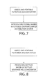
- FIG. 7 is a block diagram showing one exemplary method of utilizing potable water produced by the systems of this invention for one desired application, e.g., introducing potable water into a public or private water distribution system;
- FIG. 8 is a block diagram showing another exemplary method of utilizing potable water produced by the systems of this invention for another desired application, e.g., producing bottled drinking water;
- FIG. 9 is a block diagram showing another exemplary method of utilizing potable water produced by the systems of this invention for another desired application, e.g., replenishing an aquifer by introducing the potable water into the aquifer;
- FIG. 10 is a block diagram showing another exemplary method of utilizing potable water produced by the systems of this invention for another desired application, e.g., remediating a contaminated aquifer by introducing the potable water into the aquifer;
- FIG. 11 is a block diagram showing another exemplary method of utilizing potable water produced by the systems of this invention for another desired application, e.g., remediating contaminated soil by introducing the potable water into the soil;
- FIG. 12 is a block diagram showing another exemplary method of utilizing potable water produced by the systems of this invention for another desired application, e.g., drought relief by providing the potable water for irrigating crops;
- FIG. 13 is a block diagram showing another exemplary method of utilizing potable water produced by the systems of this invention for another desired application, e.g., material manufacturing by providing the potable water for manufacturing a product;
- FIG. 14 is a block diagram showing another exemplary method of utilizing potable water produced by the systems of this invention for another desired application, e.g., food processing by providing the potable water for processing a food;
- FIG. 15 is a block diagram showing another exemplary method of utilizing water pumped from a body of water utilizing wave action for a desired application, e.g., air conditioning by introducing pumped water into a cooling system; and
- FIG. 16 is a block diagram showing another exemplary method of utilizing water pumped from a body of water utilizing wave action for a desired application, e.g., aquaculture by pumping the water from one location in an aquaculture farm to another location therein to circulate nutrients.
- a desired application e.g., aquaculture by pumping the water from one location in an aquaculture farm to another location therein to circulate nutrients.
- FIG. 1 a system for producing potable water from salt water in a body of water, e.g., a sea, having waves.
- the system basically comprises an AWECS and a portable filtration-anchor system.
- the AWECS is a system in the form of articulated barge and includes a desalination system.
- the desalination system is constructed similarly to the AWECS described above, e.g., it includes a forward barge 12 A, a rear barge 12 B and an intermediate or center barge 12 C.
- the barges are hinged to each other and include at least one pump 13 A straddling the forward barge 12 A and center barge 12 C and at least one pump 13 B straddling the rear barge 12 B and center barge 12 C.
- a reverse osmosis membrane 15 is disposed in one of the barges and is arranged to process filtered salt water provided from the portable filtration-anchor system to produce potable water.
- the portable filtration-anchor system is arranged for disposition on the floor or bed of the body of salt water to filter the salt water which is brought into it and to provide the filtered salt water to the desalination system on the articulated barge system.
- Power for drawing the salt water from the body of water into the filter-anchor, where it is filtered into filtered salt water, and for providing the filtered saltwater to the desalination system on the articulated barge system is accomplished by the action of the waves of the body of water on the barge system.
- the AWECS includes pumps which are powered by the energy extracted from the action of the waves on the barge system.
- FIG. 1 one exemplary embodiment of an AWECS 10 constructed in accordance with an exemplary embodiment of the present invention is shown in FIG. 1 and includes the three previously identified articulated barges 12 A, 12 B and 12 C.
- the barges are anchored using, for example, a 3-point anchoring system utilizing mooring buoys 14 , 16 , 18 having filter-anchor units 20 , 22 , 24 .
- the filter-anchor units 20 , 22 , 24 form one exemplary embodiment of the portable filtration-anchor system and serve as intakes for the articulated barges, allowing seawater to be pre-filtered prior to entering designated barges, with negligible effects on aquatic life.
- This system is, for example, a containerized version of the SWISS (as discussed in the Background, above).
- the seawater will be pressurized and processed through an onboard reverse osmosis system.
- the onboard reverse osmosis system can be of any suitable construction and includes a conventional reverse osmosis (RO) membrane 15 .
- the reverse osmosis system operates in a conventional manner to produce potable water from salt water exposed to the RO membrane.
- the fact that the RO membrane is located in the articulated barge system renders it self-cleaning.
- the barge system is floating on the body of salt water where it is exposed to the rocking action of the waves (an exemplary direction of the wave flow is shown by the arrow in FIG. 1 ), this rocking action effectively shakes or otherwise disturbs the RO membrane to effectively clean it.
- the RO membrane is effectively self-cleaning.
- the exemplary potable water producing system of this invention shown in FIG. 1 and described further below can produce an average of 100,000 gallons per day (gpd) of potable water. This value is based on 200,000 gpd of source water taken in through the sand filtration system. However, it is intended that the AWECS 10 will operate in greater and lesser seas, wherein the potable-water production will vary with the sea conditions.
- the filter-anchor units 20 , 22 , 24 are preferably built to be transportable via over-the-road trucking (as are all of the AWECS components).
- the small barge-like filter-anchors 20 , 22 , 24 include respective interior chambers 48 , which are preferably lined with a porous fabric, such as a woven geotextile bag 26 (e.g., a Geotube® brand permeable fabric) filled with sand 28 .
- a porous fabric such as a woven geotextile bag 26 (e.g., a Geotube® brand permeable fabric) filled with sand 28 .
- the permeability of the geotextile is in gallons per square feet. It will not be the restricting permeability of the system.
- a porous cover formed of the same material as the bag 26 , may be provided over the body of sand within the chamber 48 to hold the sand in place within the chamber.
- the sand 28 to be used in the filter-anchors 20 , 22 , 24 is preferably coarse washed sand placed into the geotextile bag 26 .
- the estimated coefficient of permeability (K) of the sand is expected to be between 0.003 and 0.00003 ft/s. Any combination of engineered sand and gravel may be used to obtain best filtering results
- the surface area for a single filter may be 30′ ⁇ 6′ or 180 square feet.
- the surface area would be approximately 540 square feet.
- all three units would allow 1.62 cubic feet/second or 12.1 gallons/second. This translates to 726 gallons per minute or 1,045,440 gallons per day.
- Each modular filter-anchor 20 , 22 , 24 is estimated to handle approximately 348,480 gallons/day, depending on the sea state.
- the AWECS 10 is designed to be deployed (e.g., floated) in a body of salt water, e.g., sea having, for example, a 1.5-meter significant wave height and seven-second period.
- a body of salt water e.g., sea having, for example, a 1.5-meter significant wave height and seven-second period.
- the AWECS 10 will operate in greater and lesser seas or bodies of salt water, and the potable-water production will vary with the sea/salt water conditions.
- each filter-anchor 20 , 22 , 24 is in the form of a modular filter housing 30 having an exterior 50 and an interior chamber 48 .
- the woven geotextile bag 26 with the sand 28 therein is disposed within the interior chamber 48 .
- the housing 50 includes at least one inlet 52 for providing sea water to the interior chamber 48 , and at least one water conduction outlet conduit 38 for enabling the filtered water to exit (i.e., be pumped out) the interior chamber 48 .
- the filter-anchor 20 includes at least one feed line 36 located in the interior chamber 48 to provide the filtered water to the water conduction outlet conduit 38 .
- the feed lines 36 are perforated or otherwise allow for the salt water filtered by the sand that is in chamber 48 to enter the lines 36 .
- the feed lines 36 can be V-line well piping. Only water that passes through the filter (e.g., the geotextile bag 26 ) may enter the feed lines 36 .
- the modular filter housing 30 may be constructed from steel sheet 32 .
- the at least one inlet 52 may be in the form of apertures or openings in the side of the filter housing 30 and may have manually or automatically controlled hatches to control water flow therethrough.
- each housing 30 is a barge-like structure that can be floated into place adjacent the AWECS. That is, the modular filter housing 30 will, first, be able to barge the sand 28 in the geotextile bag 26 to the site where it will be used to make potable water.
- the sheet steel 32 will be used for the skin, for example, is approximately 3 ⁇ 8 inch thick.
- beam members 34 either I-beams or channel beams to provide structural support for the housing.
- the modular filter housing 30 will preferably be protected from electrolysis using sacrificial zinc anodic protection. It may also be painted to reduce the surface corrosion, as determined necessary. While the exemplary embodiment of the filter housing 30 is shown and described as being formed of sheet steel, other materials can be used. For example, another possible material for the filter housing 30 may be concrete.
- the geotextile bag 26 may be, for example, polyethylene, woven fabric. Seam strength may be, for example, approximately 450 pounds per inch pull.
- the bag 26 (or a porous cover formed of the same material as the bag) serves to keep the sand 28 from washing from the submerged filter structure.
- the feed lines 36 may be constructed of, for example, high density polyethylene, and may be encased in filter fabric and stone sleeve to prevent sand 28 from being pulled into the feed lines 36 .
- the feed lines 36 serve to transport filtered salt water, e.g., sea water, through a manifold 37 to preferably, a single water conduction outlet conduit 38 that is, for example, six inches in diameter.
- the water conduction conduit 38 penetrates the filter housing 30 and is the source for water lines 60 , 62 , 64 (see FIG. 1 ) extending to the AWECS pumps.
- two four-inch feed lines 36 connect to the six-inch water conduction outlet conduit 38 .
- the operation of the AWECS pumps 13 A and 13 B pulls the filtered sea water from the chamber 48 to the reverse osmosis membrane 15 in the AWECS.
- the power for operating the pumps is provided by the wave energy captured by the articulating barges 12 A- 12 C.
- the filter housing 30 may have manually-operated scuttles or hatches at the inlets 52 in the sides 44 of the housing to allow for flooding of the entire filter housing 30 .
- the number of hatches will be sufficient to allow for a controlled submersion and re-flotation of the unit.
- the re-flotation will be done by, first, attaching a snorkel (not shown) through the free-surface of the water and, then, using a submerged pump (not shown) to de-water the filter system. Air is drawn in through the snorkel to replace the purged water in the bilge and gunnel areas of the modular filter-anchors 20 , 22 , 24 .
- the filter housing 30 may be capped and made water tight prior to re-float to allow removal of as much water as possible from this area to provide the additional buoyancy required for re-float.
- a method of anchoring a wave energy conversion system 10 and providing filtered water to the desalination system includes the steps of towing an articulated barges for converting wave energy into energy used to pump water to an RO membrane to generate potable water to a location in an ocean, sea or other salt water body having waves, towing at least one filter-anchor 20 , 22 , 24 (as described above) to the same location and sinking each filter-anchor to the ocean bed. That action is accomplished by filling the interior chamber of the filter housing with water.
- a mooring buoy 14 , 16 , 18 is provided for each filter-anchor 20 , 22 , 24 at their respective locations.
- the mooring buoys 14 , 16 , 18 are attached to respective ones of the filter-anchors 20 , 22 , 24 by respective mooring lines 54 , 56 , 58 .
- the filter-anchors 20 , 22 , 24 are attached to the articulated barges 12 .
- Source salt water to the RO membrane is then provided from the filter-anchors via the water lines 60 , 62 and 64 by the operation of the AWECS pumps.
- an AWECS pump ( 13 A or 13 B) comprises a bi-directional linear pump 100 that is powered by the relative motions of the barges 12 A/ 12 C or 12 B/ 12 C via movable couplings (e.g., hinges).
- movable couplings e.g., hinges
- movement of a piston 102 A within a piston chamber 102 B as driven by a piston rod 102 C whose other end (not shown) is coupled to either barge 12 A or 12 B causes sea water from a filter-anchor unit to be moved in opposite linear directions.
- a “flow rectifier” 200 is required to convert this bi-directional sea water flow into a unidirectional fluid flow.
- This unidirectional sea water flow is then delivered to the reverse osmosis membrane 15 .
- the housing 102 B comprises pressure taps 104 that feed into corresponding pressure tap pairs 204 in the flow rectifier 200 via control pressure lines 106 .
- Intake/Exhaust taps 108 are coupled via intake/exhaust lines 110 respectively to rectifier passageways 205 .
- Rectifier valve pairs 206 A and 206 B (e.g., cone-head valves) correspond to the pressure tap pairs 204 .
- the valves 206 A/ 206 B are received in valve seats 208 when the valves are closed.
- Pressure relief taps 209 are provided and wherein seat pressure relief taps 210 are coupled via pressure relief lines 212 .
- Flow ports 214 act as the input ports for the sea water and are in fluid communication with a corresponding filter-anchor unit 20 , 22 or 24 .
- Arrows 112 indicate the corresponding piston motion direction while arrows 114 indicate the pressure-force direction.
- Arrows 216 indicate the sea water flow direction.
- the high-pressure sea water feed flow line is indicated by 218 while the low-pressure intake flow line is indicated by 220 .
- a high pressure manifold 222 takes the high-pressure sea water flow via path 224 to the reverse osmosis membrane 50 .
- the piston/rod assembly 102 A/ 102 C is excited by an alternating energy source, namely, the water waves.
- the piston/rod assembly 102 A/ 102 C travels in alternating directions over the period associated with the water wave in the piston housing 102 B.
- the motions create alternating pressures in the taps 104 / 204 due to the alternating piston-rod assembly motions 112 .
- the alternating pressures are transmitted through the control pressure lines 106 , producing alternating pressure forces with directions shown as 114 .
- the piston-rod assembly motions 112 cause the sea water in the pump 100 to be alternatively expelled at high pressure and refilled at low pressure through the intake/exhaust taps 108 .
- the alternating flows through the taps 108 are transmitted through the intake/exhaust lines 110 .
- the pressure forces 114 in the control pressure lines 106 alternately cause the cone-head valves 206 A and 206 B to open and close.
- the cone-head of the valves mate with the conical valve seats 208 when the valve is closed.
- sea water is passed into the seat 208 through the seat pressure relief tap 210 which is partially supplied by the pressure relief tap 209 .
- the taps 209 and 210 are interconnected by the pressure relief lines 212 .
- the resulting flows in the sea water flow ports 214 are in the directions indicated by 220 .
- the high pressure flow in the high pressure feed flow lines 218 travel in the direction 216 .
- the low pressure flow in the low pressure intake flow lines 220 in the direction 221 come from the corresponding filter-anchor unit 20 , 22 or 24 .
- the high pressure flow components through flow lines 218 are combined in a manifold 224 and this combined flow 226 is supplied to the reverse osmosis membrane 58 .
- the potable or pure water produced by the systems of this invention can be utilized in various ways in accordance with various methods of this invention.
- the potable water produced by the systems of this invention can be supplied either directly or indirectly to public or privately owned water distribution systems, such as shown in FIG. 7 . That can be accomplished by use of a distribution system including conduits, valves, meters, etc. which couple the AWECS to an inlet of the public or privately owned water distribution system.
- the potable water produced by the systems of this invention can be supplied to water bottlers for the production of bottled drinking water, such as shown in FIG. 8 .
- the potable water can be used to supply bottled water for disaster relief applications.
- the systems of this can be deployed to areas that recently experienced natural or man-made disasters that have rendered the localized water supply inoperable or unsafe, such as Haiti, Fukishima, and other disaster regions that require outside sources of potable water.
- the systems can then be operated to produce potable water which can be bottled for distribution to the persons affected by the disaster.
- the systems of this invention can also be used in accordance with another method of this invention to serve as a fresh water source for material manufacturing, such as shown in FIG. 13 , and food processing, such as shown in FIG. 14 , since the water produced by the reverse osmosis system of the AWECS is very pure.
- the systems of this invention can be deployed to provide drought relief in accordance with another method of this invention, such as shown in FIG. 12 .
- the AWECS can provide either water source, with salt water pumping into irrigation distribution networks, being a viable capability of the AWECS.
- the systems of this invention can be deployed for aquifer recharging applications in accordance with still another method of this invention, such as shown in FIG. 9 .
- FIG. 9 it is well known that existing water aquifers are being drained at a significant, and perhaps alarming, rate.
- One of the more publicized examples is in the State of Florida, where the freshwater levels have dropped significantly, creating dangerous sinkholes.
- the potable water produced by the AWECS can be used to recharge the aquifer and thereby stabilize the sinkhole situation.
- the systems of this invention can be used in accordance with methods of this invention to recharge or replenish aquifers for any reason, such as shown in FIG. 9 .
- Such recharging or replenishing could provide a natural and far-reaching water distribution mechanism for regions where the aquifers are in danger.
- the systems of this invention can be deployed for remediation of aquifer contamination, such as shown in FIG. 10 and/or ground or soil contamination, such as shown in FIG. 11 , in accordance with yet other methods of this invention.
- aquifer contamination such as shown in FIG. 10
- ground or soil contamination such as shown in FIG. 11
- Existing techniques for remediation include pumping and treating of the contaminated water, and the infusion of air into the geological substrate to flush out the easily volatilized contaminate.
- the infusion of potable water back into the ground can assist in the flushing of the contaminants from the ground, thereby providing a viable and low cost remediation technique.
- the AWECS can be used to merely pump seawater without treating that water with reverse osmosis in accordance with another method of this invention.
- the AWECS can be used, as shown in FIG. 15 , for effecting air conditioning by introducing water (salt or fresh) pumped by wave action from a body of water into a cooling system.
- it can be used, as shown in FIG. 16 , in aquaculture farms to pump salt or fresh water from one location to another to circulate nutrients where the temperature gradients create stagnant or oxygen deficient conditions.
Landscapes
- Engineering & Computer Science (AREA)
- Chemical & Material Sciences (AREA)
- Water Supply & Treatment (AREA)
- Chemical Kinetics & Catalysis (AREA)
- Life Sciences & Earth Sciences (AREA)
- Hydrology & Water Resources (AREA)
- General Engineering & Computer Science (AREA)
- Nanotechnology (AREA)
- Environmental & Geological Engineering (AREA)
- Mechanical Engineering (AREA)
- Organic Chemistry (AREA)
- Combustion & Propulsion (AREA)
- Structural Engineering (AREA)
- Civil Engineering (AREA)
- Health & Medical Sciences (AREA)
- Public Health (AREA)
- Separation Using Semi-Permeable Membranes (AREA)
Abstract
A potable water producing system for disposition at a salt water body and methods of producing potable water are provided. The system includes a wave energy conversion system (AWECS) and a portable filtration-anchor system. The AWECS forms a floating articulated barge having a desalination system including a reverse osmosis membrane. The filtration-anchor system is submerged in the salt water body and includes a sand filter to filter the adjacent salt water for providing the filtered salt water to the desalination system on the articulated barge. Wave action on the articulated barge provides energy to pump the filtered salt water from the sand filter to the reverse osmosis member to produce potable water. The wave action on the articulated barge effects the shaking of the reverse osmosis filter, thereby rendering it self-cleaning. The potable water can be used for various applications, e.g., bottling, replenishing aquifers, ground and/or aquifer remediation, irrigation, etc.
Description
This U.S. National Phase application claims the benefit under 35 U.S.C. § 371 of PCT Application No. PCT/US2014/056243 filed on Sep. 18, 2014 which claims the benefit under 35 U.S.C. § 120 of application Ser. No. 14/037,684 (now U.S. Pat. No. 8,778,176) filed on Sep. 26, 2013 and entitled “Modular Sand Filtration-Anchor System and Wave Energy Water Desalination System Incorporating the Same” which in turn is a Continuation-in-Part Application, and claims the benefit under 35 U.S.C. § 120, of application Ser. No. 13/929,171 (now U.S. Pat. No. 8,784,653) filed on Jun. 27, 2013 and entitled “Modular Sand Filtration-Anchor System and Wave Energy Water Desalination System Incorporating the Same” which in turn takes the benefit under 35 U.S.C. § 119(e) of Application Ser. No. 61/668,213 filed on Jul. 5, 2012 entitled “Modular Sand Filtration-Anchor System” and all of whose entire disclosures are incorporated by reference. PCT Application No. PCT/US2014/056243 filed on Sep. 18, 2014 which claims the benefit under 35 U.S.C. § 119(e) of Application Ser. No. 62/028,895 filed on Jul. 25, 2014 and entitled “Methods of Using Potable Water Produced by Wave Energy Desalination” and all of whose entire disclosures are also incorporated by reference herein.
The present invention is generally directed to the generation of potable water. More particularly, the present invention is directed to articulated wave energy conversion system (AWECS) with reverse osmosis (RO) membranes to generate potable water for various applications.
Desalinization plants are located around the world, and are operated using electricity to pressurize the incoming source water. Depending on the location, there may be pretreatment requirements to optimize the influent for processing through the RO membranes.
The U.S. Department of Interior (DOI) funded the Subfloor Water Intake Structure System (SWISS), currently utilized in desalination plants in California and Japan. The SWISS approach is to install a permanent subfloor well/intake system for the source-water for the traditional shore structures. The in-situ sand provides the filtration media. See, for example, Lovo, Robert, “Initial Evaluation of the Subfloor Water Intake Structure System (SWISS) vs. Conventional Multimedia Pretreatment Techniques,” Assistance Agreement No. 98-FC-81-0044, Desalination Research and Development Program Report No. 66, U.S. Dept. of Interior, May 2001.
Ocean wave-energy conversion is directed to the exploitation of ocean wave energy to produce energy in one or more of four forms, those being hydraulic, pneumatic, mechanical or electrical. See McCormick, “Ocean Wave Energy Conversion,” published by Wiley-Interscience, New York (1981, reprinted by Dover Publication, Long Island, N.Y. in 2007). The articulated-barge wave-energy conversion system dates back to the 1970's when both Sir Christopher in the United Kingdom and Glen Hagen of the United States suggested the system. The system was studied in the late 1970's by P. Haren (1978) at MIT. He found that the optimum articulated-barge configuration was a three-barge system. In the 1980's, Dr. Peter McCabe showed that the efficiency of the three-barge system could be substantially improved by suspending an inertial-damping plate below the center barge. Dr. McCabe, then, produced a prototype of the system, coined the McCabe Wave Pump (MWP), which was deployed and studied in the Shannon Estuary for approximately nine years. See, U.S. Pat. No. 5,132,550 (McCabe). The MWP was primarily designed as a producer of potable water.
Ocean Energy Systems (OES) is in the business of designing and manufacturing articulated-barge systems to produce potable water by reverse-osmosis (RO) desalination of sea water. U.S. Patent Publication No. 2009/0084296 (McCormick), which is incorporated by reference herein, describes a system directed to a wave-powered device having enhanced motion. In particular, there is disclosed an articulated barge wave energy converter system, which shall hereinafter be referred to as the AWECS. See also U.S. Patent Publication No. 2010/0320759 (Lightfoot, et al.). The AWECS basically comprises a forward barge, a rear barge and an intermediate or center barge, all of which arranged to float on a body of water having waves. The barges are hingedly coupled together so that they can articulate with respect to each other in response to wave motion. The AWECS also includes high-pressure pumps which straddle and pivotably connect the barge-pairs, e.g., at least one pump connects the forward barge and the intermediate barge, and at least another pump connects the rear barge and the intermediate barge. The pumps are designed to draw in the water through a pre-filter, pressurize the water, and deliver the water to an on-board reverse osmosis (RO) desalination system. That system includes an RO membrane. As an incoming wave makes contact with the forward barge first, the hydraulic fluid in the pump(s) coupled between the forward barge and the center barge are driven in a first direction; as the wave continues, the hydraulic fluid in the pump(s) coupled between the rear barge and the center barge are driven in a second opposite direction. The end results are bi-directional hydraulic pumps.
In U.S. Patent Publication No. 2014/0091575 (McCormick, et al.), there is disclosed an AWECS arranged for producing electrical energy from the wave energy. To that end it makes use of an AWECS similar to that described above, except that it can make use of a commercially-available rotary-vane pump to drive a generator to produce the electricity. To that end, the invention of the '575 application entails a floating device having a first portion (e.g., a first barge) movably coupled (e.g., hinged) to a second portion (e.g., a second barge); at least one hydraulic or pneumatic pump (e.g., a linear pump) coupled between the first portion the said second portion, the hydraulic pump driving a hydraulic fluid therein when the first portion moves with respect to the second portion due to wave energy. A fluid rectifier is provided in the AWECS and is in fluid communication with the at least one hydraulic or pneumatic pump, that generates a unidirectional hydraulic or pneumatic fluid flow. A rotary vane pump is coupled to the fluid rectifier. The rotary vane pump uses the unidirectional flow to generate a rotational motion via a drive member. A rotating electrical generator (e.g., a DC generator) is coupled to that drive member, so that the drive member causes the rotating electrical generator to generate electricity when the drive member is rotating.
All references cited herein are incorporated herein by reference in their entireties.
In accordance with one aspect of this invention a system for producing potable water for various applications is provided. The system basically comprises an articulating barge system and at least one filter-anchor. The articulated barge system is arranged for floating on a body of salt water having waves and includes a desalination system to produce potable water from filtered salt water. The barge system is arranged for converting energy of the waves into energy to pump the filtered salt water to the desalination system. The desalination system includes a reverse osmosis membrane, which is arranged to be self-cleaned by the action of the waves on the barge system. The at least one filter-anchor is arranged for placement on the floor of the body of salt water and comprises a filter housing and a filter. The filter housing has an interior chamber, at least one inlet, at least one outlet, and a filter, e.g., a sand filter, located within the filter housing. The at least one inlet is arranged for providing salt water to the filter. The filter is adapted to filter the salt water to produce filtered salt water. The outlet of the at least one filter-anchor is coupled to the desalination system, whereupon the salt water can be drawn into the filter and filtered to produce filtered water which can be pumped from the outlet to the desalination system by the energy of the waves. The potable water produced by the desalination system can then be used for various purposes in accordance with method aspects of this invention (to be discussed later).
In accordance with one preferred embodiment of a system of this invention the inlets for providing sea water to the filter-anchor may provide for a surface intake velocity of less than 0.5 feet per second to restrict incursion of fish larva and macro or micro vertebrae. The filter-anchor may be of a size to permit container transportable via truck transportation. The interior chamber of the filter anchor may be substantially filled with clean, washed, coarse sand, from either a local beach or shoreline source or from sand obtained from a commercial sand source. The filter housing may have hatches between the exterior and the interior chamber which, when opened, provide for submersion of the filter housing via flooding of the interior chamber and controlled sinking of the filter-anchor to the floor of the body of salt water. The filter-anchor, prior to use as a filter, may be floatable and towable to a deployment site in the body of salt water. The filter-anchors may be provided with associated (respective) mooring buoys, which are preferably attached to the filter-anchors by a mooring line. At least one submersible pump and submersible air snorkel may be included such that the filter-anchor is re-floatable when the hatches are in a closed position, wherein the interior chamber is substantially filled with air, wherein the submersible pump and air snorkel are activatable to float the filter-anchor.
Other aspects of this invention entail methods of using potable water produced from salt water using wave energy. Those methods entail floating an articulated barge system on a body of salt water having waves. The barge system includes a desalination system to produce potable water from filtered salt water. The desalination system includes a reverse osmosis membrane. At least one filter-anchor is disposed on the floor of the body of salt water. The filter-anchor comprises a filter housing and a filter. The filter housing has an interior chamber, at least one inlet, at least one outlet, and a filter located within the filter housing. The at least one inlet is arranged for providing salt water to the filter. The filter is adapted to filter the salt water to produce filtered salt water. The method also entails coupling the outlet of the filter-anchor to the desalination system on the barge system and using the barge system to convert the energy of the waves into energy to pump the filtered salt water to the desalination system, whereupon the filtered salt water is converted to potable water utilizing the reverse osmosis membrane. The reverse osmosis membrane is self-cleaned by the action of the waves on the barge system. Among the various applications for using the potable water produced from salt water using wave powered reverse osmosis are the following: producing bottled drinking water; introducing potable drinking water into a drinking water system (e.g., public or private); replenishing an aquifer by introducing potable water into the aquifer; remediating a contaminated aquifer by introducing potable water into the aquifer; remediating contaminated soil by introducing potable water into the soil; effecting drought relief by providing potable water for irrigating crops; effecting material manufacturing by providing potable water for manufacturing a product; effecting material manufacturing by providing potable water for manufacturing a product; and effecting food processing by providing potable water for processing a food.
In accordance with another aspect of this invention methods for pumping seawater using wave energy for various applications are provided. Those methods entail floating an articulated barge system on a body of water (salt or fresh) having waves and using the barge system to convert the energy of the waves into energy to pump the water from the body of water to some location for various applications. Among the various applications for using the pumped water produced by those methods are the following: effecting air conditioning by introducing pumped water into a cooling system; and effecting aquaculture by pumping the water from one location in an aquaculture farm to another location therein to circulate nutrients.
The invention will be described in conjunction with the following drawings in which like reference numerals designate like elements and wherein:
Referring now to the drawing wherein like characters refer to like parts, there is shown in FIG. 1 a system for producing potable water from salt water in a body of water, e.g., a sea, having waves. The system basically comprises an AWECS and a portable filtration-anchor system. The AWECS is a system in the form of articulated barge and includes a desalination system. The desalination system is constructed similarly to the AWECS described above, e.g., it includes a forward barge 12A, a rear barge 12B and an intermediate or center barge 12C. The barges are hinged to each other and include at least one pump 13A straddling the forward barge 12A and center barge 12C and at least one pump 13B straddling the rear barge 12B and center barge 12C. A reverse osmosis membrane 15 is disposed in one of the barges and is arranged to process filtered salt water provided from the portable filtration-anchor system to produce potable water. The portable filtration-anchor system is arranged for disposition on the floor or bed of the body of salt water to filter the salt water which is brought into it and to provide the filtered salt water to the desalination system on the articulated barge system. Power for drawing the salt water from the body of water into the filter-anchor, where it is filtered into filtered salt water, and for providing the filtered saltwater to the desalination system on the articulated barge system is accomplished by the action of the waves of the body of water on the barge system. In particular, as will be discussed in detail later the AWECS includes pumps which are powered by the energy extracted from the action of the waves on the barge system.
The system for producing potable water will be illustrated in more detail with reference to the following embodiments, but it should be understood that the present invention is not deemed to be limited thereto. To that end, one exemplary embodiment of an AWECS 10 constructed in accordance with an exemplary embodiment of the present invention is shown in FIG. 1 and includes the three previously identified articulated barges 12A, 12B and 12C. The barges are anchored using, for example, a 3-point anchoring system utilizing mooring buoys 14, 16, 18 having filter- anchor units 20, 22, 24. The filter- anchor units 20, 22, 24 form one exemplary embodiment of the portable filtration-anchor system and serve as intakes for the articulated barges, allowing seawater to be pre-filtered prior to entering designated barges, with negligible effects on aquatic life. This system is, for example, a containerized version of the SWISS (as discussed in the Background, above).
The seawater will be pressurized and processed through an onboard reverse osmosis system. The onboard reverse osmosis system can be of any suitable construction and includes a conventional reverse osmosis (RO) membrane 15. The reverse osmosis system operates in a conventional manner to produce potable water from salt water exposed to the RO membrane. However, the fact that the RO membrane is located in the articulated barge system renders it self-cleaning. In this regard, since the barge system is floating on the body of salt water where it is exposed to the rocking action of the waves (an exemplary direction of the wave flow is shown by the arrow in FIG. 1 ), this rocking action effectively shakes or otherwise disturbs the RO membrane to effectively clean it. Thus, the RO membrane is effectively self-cleaning.
For the design sea (for example, a 1.5-meter significant wave height and 7-second period), the exemplary potable water producing system of this invention shown in FIG. 1 and described further below can produce an average of 100,000 gallons per day (gpd) of potable water. This value is based on 200,000 gpd of source water taken in through the sand filtration system. However, it is intended that the AWECS 10 will operate in greater and lesser seas, wherein the potable-water production will vary with the sea conditions.
The filter- anchor units 20, 22, 24 are preferably built to be transportable via over-the-road trucking (as are all of the AWECS components).
As can be seen in FIGS. 3 and 5 , and which will be described later, the small barge-like filter- anchors 20, 22, 24 include respective interior chambers 48, which are preferably lined with a porous fabric, such as a woven geotextile bag 26 (e.g., a Geotube® brand permeable fabric) filled with sand 28. The permeability of the geotextile is in gallons per square feet. It will not be the restricting permeability of the system. As an alternative to a bag 26, a porous cover, formed of the same material as the bag 26, may be provided over the body of sand within the chamber 48 to hold the sand in place within the chamber.
The sand 28 to be used in the filter- anchors 20, 22, 24 is preferably coarse washed sand placed into the geotextile bag 26. The estimated coefficient of permeability (K) of the sand is expected to be between 0.003 and 0.00003 ft/s. Any combination of engineered sand and gravel may be used to obtain best filtering results
It is anticipated that (for example) 200,000 gpd of supply water will be pulled through the three filter- anchors 20, 22, 24 in the present example. In this exemplary embodiment, the surface area for a single filter may be 30′×6′ or 180 square feet. For three such filter- anchors 20, 22, 24, the surface area would be approximately 540 square feet. At a rate of 0.003 fps, all three units would allow 1.62 cubic feet/second or 12.1 gallons/second. This translates to 726 gallons per minute or 1,045,440 gallons per day. Each modular filter- anchor 20, 22, 24 is estimated to handle approximately 348,480 gallons/day, depending on the sea state.
As stated above, the AWECS 10 is designed to be deployed (e.g., floated) in a body of salt water, e.g., sea having, for example, a 1.5-meter significant wave height and seven-second period. However, the AWECS 10 will operate in greater and lesser seas or bodies of salt water, and the potable-water production will vary with the sea/salt water conditions.
As can be seen in FIGS. 2-5 , each filter- anchor 20, 22, 24 is in the form of a modular filter housing 30 having an exterior 50 and an interior chamber 48. The woven geotextile bag 26 with the sand 28 therein is disposed within the interior chamber 48. The housing 50 includes at least one inlet 52 for providing sea water to the interior chamber 48, and at least one water conduction outlet conduit 38 for enabling the filtered water to exit (i.e., be pumped out) the interior chamber 48.
The filter-anchor 20 includes at least one feed line 36 located in the interior chamber 48 to provide the filtered water to the water conduction outlet conduit 38. The feed lines 36 are perforated or otherwise allow for the salt water filtered by the sand that is in chamber 48 to enter the lines 36. The feed lines 36 can be V-line well piping. Only water that passes through the filter (e.g., the geotextile bag 26) may enter the feed lines 36.
The modular filter housing 30 may be constructed from steel sheet 32. The at least one inlet 52 may be in the form of apertures or openings in the side of the filter housing 30 and may have manually or automatically controlled hatches to control water flow therethrough.
Referring now to FIGS. 2-5 more details of the construction of the modular filter housing 30 will be provided. To that end, each housing 30 is a barge-like structure that can be floated into place adjacent the AWECS. That is, the modular filter housing 30 will, first, be able to barge the sand 28 in the geotextile bag 26 to the site where it will be used to make potable water. The sheet steel 32 will be used for the skin, for example, is approximately ⅜ inch thick. There will be various beam members 34 either I-beams or channel beams to provide structural support for the housing. Moreover, the modular filter housing 30 will preferably be protected from electrolysis using sacrificial zinc anodic protection. It may also be painted to reduce the surface corrosion, as determined necessary. While the exemplary embodiment of the filter housing 30 is shown and described as being formed of sheet steel, other materials can be used. For example, another possible material for the filter housing 30 may be concrete.
The geotextile bag 26 may be, for example, polyethylene, woven fabric. Seam strength may be, for example, approximately 450 pounds per inch pull. The bag 26 (or a porous cover formed of the same material as the bag) serves to keep the sand 28 from washing from the submerged filter structure.
The feed lines 36 may be constructed of, for example, high density polyethylene, and may be encased in filter fabric and stone sleeve to prevent sand 28 from being pulled into the feed lines 36.
The feed lines 36 serve to transport filtered salt water, e.g., sea water, through a manifold 37 to preferably, a single water conduction outlet conduit 38 that is, for example, six inches in diameter. The water conduction conduit 38 penetrates the filter housing 30 and is the source for water lines 60, 62, 64 (see FIG. 1 ) extending to the AWECS pumps. For example, two four-inch feed lines 36 connect to the six-inch water conduction outlet conduit 38. The operation of the AWECS pumps 13A and 13B pulls the filtered sea water from the chamber 48 to the reverse osmosis membrane 15 in the AWECS. The power for operating the pumps is provided by the wave energy captured by the articulating barges 12A-12C.
As can be seen in schematically in FIG. 2 , the filter housing 30 may have manually-operated scuttles or hatches at the inlets 52 in the sides 44 of the housing to allow for flooding of the entire filter housing 30. The number of hatches will be sufficient to allow for a controlled submersion and re-flotation of the unit. The re-flotation will be done by, first, attaching a snorkel (not shown) through the free-surface of the water and, then, using a submerged pump (not shown) to de-water the filter system. Air is drawn in through the snorkel to replace the purged water in the bilge and gunnel areas of the modular filter- anchors 20, 22, 24. The filter housing 30 may be capped and made water tight prior to re-float to allow removal of as much water as possible from this area to provide the additional buoyancy required for re-float.
A method of anchoring a wave energy conversion system 10 and providing filtered water to the desalination system is also provided. The method includes the steps of towing an articulated barges for converting wave energy into energy used to pump water to an RO membrane to generate potable water to a location in an ocean, sea or other salt water body having waves, towing at least one filter- anchor 20, 22, 24 (as described above) to the same location and sinking each filter-anchor to the ocean bed. That action is accomplished by filling the interior chamber of the filter housing with water. A mooring buoy 14, 16, 18 is provided for each filter- anchor 20, 22, 24 at their respective locations. The mooring buoys 14, 16, 18 are attached to respective ones of the filter- anchors 20, 22, 24 by respective mooring lines 54, 56, 58. The filter- anchors 20, 22, 24 are attached to the articulated barges 12. Source salt water to the RO membrane is then provided from the filter-anchors via the water lines 60, 62 and 64 by the operation of the AWECS pumps.
As mentioned earlier, the AWECS pumps 13A and 13B pull the filtered sea water from the chamber 48 to the reverse osmosis membrane 15. As shown most clearly in FIG. 6 , an AWECS pump (13A or 13B) comprises a bi-directional linear pump 100 that is powered by the relative motions of the barges 12A/12C or 12B/12C via movable couplings (e.g., hinges). As can be appreciated from FIG. 6 , movement of a piston 102A within a piston chamber 102B as driven by a piston rod 102C whose other end (not shown) is coupled to either barge 12A or 12B, causes sea water from a filter-anchor unit to be moved in opposite linear directions. As a result, a “flow rectifier” 200 is required to convert this bi-directional sea water flow into a unidirectional fluid flow. This unidirectional sea water flow is then delivered to the reverse osmosis membrane 15. The housing 102B comprises pressure taps 104 that feed into corresponding pressure tap pairs 204 in the flow rectifier 200 via control pressure lines 106. Intake/Exhaust taps 108 are coupled via intake/exhaust lines 110 respectively to rectifier passageways 205. Rectifier valve pairs 206A and 206B (e.g., cone-head valves) correspond to the pressure tap pairs 204. The valves 206A/206B are received in valve seats 208 when the valves are closed. Pressure relief taps 209 are provided and wherein seat pressure relief taps 210 are coupled via pressure relief lines 212. Flow ports 214 act as the input ports for the sea water and are in fluid communication with a corresponding filter- anchor unit 20, 22 or 24. Arrows 112 indicate the corresponding piston motion direction while arrows 114 indicate the pressure-force direction. Arrows 216 indicate the sea water flow direction. The high-pressure sea water feed flow line is indicated by 218 while the low-pressure intake flow line is indicated by 220. A high pressure manifold 222 takes the high-pressure sea water flow via path 224 to the reverse osmosis membrane 50.
In operation, the piston/rod assembly 102A/102C is excited by an alternating energy source, namely, the water waves. The piston/rod assembly 102A/102C travels in alternating directions over the period associated with the water wave in the piston housing 102B. The motions create alternating pressures in the taps 104/204 due to the alternating piston-rod assembly motions 112. The alternating pressures are transmitted through the control pressure lines 106, producing alternating pressure forces with directions shown as 114. The piston-rod assembly motions 112 cause the sea water in the pump 100 to be alternatively expelled at high pressure and refilled at low pressure through the intake/exhaust taps 108. The alternating flows through the taps 108 are transmitted through the intake/exhaust lines 110. The pressure forces 114 in the control pressure lines 106 alternately cause the cone- head valves 206A and 206B to open and close. The cone-head of the valves mate with the conical valve seats 208 when the valve is closed. When the valve is to be opened by the pressure force 114, sea water is passed into the seat 208 through the seat pressure relief tap 210 which is partially supplied by the pressure relief tap 209. The taps 209 and 210 are interconnected by the pressure relief lines 212. The resulting flows in the sea water flow ports 214 are in the directions indicated by 220. In particular, the high pressure flow in the high pressure feed flow lines 218 travel in the direction 216. The low pressure flow in the low pressure intake flow lines 220 in the direction 221 come from the corresponding filter- anchor unit 20, 22 or 24. The high pressure flow components through flow lines 218 are combined in a manifold 224 and this combined flow 226 is supplied to the reverse osmosis membrane 58.
The potable or pure water produced by the systems of this invention can be utilized in various ways in accordance with various methods of this invention. For example the potable water produced by the systems of this invention can be supplied either directly or indirectly to public or privately owned water distribution systems, such as shown in FIG. 7 . That can be accomplished by use of a distribution system including conduits, valves, meters, etc. which couple the AWECS to an inlet of the public or privately owned water distribution system.
The potable water produced by the systems of this invention can be supplied to water bottlers for the production of bottled drinking water, such as shown in FIG. 8 . Alternatively the potable water can be used to supply bottled water for disaster relief applications. For example, the systems of this can be deployed to areas that recently experienced natural or man-made disasters that have rendered the localized water supply inoperable or unsafe, such as Haiti, Fukishima, and other disaster regions that require outside sources of potable water. The systems can then be operated to produce potable water which can be bottled for distribution to the persons affected by the disaster.
The systems of this invention can also be used in accordance with another method of this invention to serve as a fresh water source for material manufacturing, such as shown in FIG. 13 , and food processing, such as shown in FIG. 14 , since the water produced by the reverse osmosis system of the AWECS is very pure.
The systems of this invention can be deployed to provide drought relief in accordance with another method of this invention, such as shown in FIG. 12 . In particular, there are productive agriculture techniques that use both fresh and salt water to support the growth of the crops. The AWECS can provide either water source, with salt water pumping into irrigation distribution networks, being a viable capability of the AWECS.
The systems of this invention can be deployed for aquifer recharging applications in accordance with still another method of this invention, such as shown in FIG. 9 . For example, it is well known that existing water aquifers are being drained at a significant, and perhaps alarming, rate. One of the more publicized examples is in the State of Florida, where the freshwater levels have dropped significantly, creating dangerous sinkholes. The potable water produced by the AWECS can be used to recharge the aquifer and thereby stabilize the sinkhole situation. In fact, the systems of this invention can be used in accordance with methods of this invention to recharge or replenish aquifers for any reason, such as shown in FIG. 9 . Such recharging or replenishing could provide a natural and far-reaching water distribution mechanism for regions where the aquifers are in danger.
The systems of this invention can be deployed for remediation of aquifer contamination, such as shown in FIG. 10 and/or ground or soil contamination, such as shown in FIG. 11 , in accordance with yet other methods of this invention. In this regard, there is a significant issue with ground and/or aquifer contamination that has been plaguing industrial-based societies, where the contamination has occurred many decades into the past but remains extant. Existing techniques for remediation include pumping and treating of the contaminated water, and the infusion of air into the geological substrate to flush out the easily volatilized contaminate. With the production of pure water by the systems of this invention, the infusion of potable water back into the ground can assist in the flushing of the contaminants from the ground, thereby providing a viable and low cost remediation technique.
It should be pointed out at this juncture that the AWECS can be used to merely pump seawater without treating that water with reverse osmosis in accordance with another method of this invention. For example, the AWECS can be used, as shown in FIG. 15 , for effecting air conditioning by introducing water (salt or fresh) pumped by wave action from a body of water into a cooling system. Alternatively, it can be used, as shown in FIG. 16 , in aquaculture farms to pump salt or fresh water from one location to another to circulate nutrients where the temperature gradients create stagnant or oxygen deficient conditions.
While the invention has been described in detail and with reference to specific embodiments thereof and methods of use, it will be apparent to one skilled in the art that various changes and modifications can be made therein without departing from the spirit and scope thereof.
Claims (20)
1. A method of producing potable water for a desired application comprising:
(a) floating an articulated barge system on a body of salt water having waves, the barge system including a desalination system to produce potable water from filtered salt water and wherein at least one bi-directional pump is positioned between portions of the barge system that articulate based on wave motion to drive the at least one bi-directional pump in two alternating directions, the desalination system including a reverse osmosis membrane;
(b) disposing at least one filter-anchor on the floor of the body of salt water, the filter anchor comprises a filter housing and a filter, the filter housing having an interior chamber, at least one inlet, at least one outlet in fluid communication with said at least one bi-directional pump, and a filter located within the filter housing, the at least one inlet being arranged for providing salt water through the filter, the filter being adapted to filter the salt water to produce filtered salt water whenever the pump is energized by wave motion to pull salt water from said at least one inlet, through said filter and into said outlet;
(c) coupling the outlet to an input to a flow rectifier and coupling an output of said flow rectifier to the desalination system;
(d) utilizing the barge system to convert the energy of the waves into energy to pump the filtered salt water, moved in two alternating directions by said at least one bi-directional pump and rectified into a unidirectional filtered salt water flow by said flow rectifier to the desalination system, whereupon the filtered salt water is converted to potable water utilizing the reverse osmosis membrane, the reverse osmosis membrane being self-cleaned by the action of the waves on the barge system; and
(e) providing the potable water for use in the desired application.
2. The method of claim 1 wherein the desired application comprises bottling the potable water.
3. The method of claim 1 wherein the desired application comprises replenishing an aquifer by introducing the potable water into the aquifer.
4. The method of claim 1 wherein the desired application comprises remediating a contaminated aquifer by introducing the potable water into the aquifer.
5. The method of claim 1 wherein the desired application comprises remediating contaminated soil by introducing the potable water into the soil.
6. The method of claim 1 wherein the desired application comprises drought relief by providing the potable water for irrigating crops.
7. The method of claim 1 wherein the desired application comprises material manufacturing by providing the potable water for manufacturing a product.
8. The method of claim 1 wherein the desired application comprises food processing by providing the potable water for processing a food.
9. The method of claim 1 wherein the desired application comprises air conditioning by providing the pumped water into a cooling system.
10. The method of claim 1 wherein the desired application comprises aquaculture and wherein the water is pumped from one location in an aquaculture farm to another location therein to circulate nutrients.
11. A method of producing potable water for a desired application comprising:
(a) floating an articulated barge system on a body of fresh water having waves, the barge system including a reverse osmosis membrane to produce potable water from filtered fresh water and wherein at least one bi-directional pump is positioned between portions of the barge system that articulate based on wave motion to drive the at least one bi-directional pump in two alternating directions;
(b) disposing at least one filter-anchor on the floor of the body of fresh water, the filter anchor comprises a filter housing and a filter, the filter housing having an interior chamber, at least one inlet, at least one outlet in fluid communication with said at least one bi-directional pump, and a filter located within the filter housing, the at least one inlet being arranged for providing fresh water through the filter, the filter being adapted to filter the fresh water to produce filtered fresh water whenever the pump is energized by wave motion to pull fresh water from said at least one inlet, through said filter and into said outlet;
(c) coupling the outlet to an input to a flow rectifier and coupling an output of said flow rectifier to the reverse osmosis membrane;
(d) utilizing the barge system to convert the energy of the waves into energy to pump the filtered salt water, moved in two alternating directions by said at least one bi-directional pump and rectified into a unidirectional filtered fresh water flow by said flow rectifier to the reverse osmosis membrane, whereupon the filtered fresh water is converted to potable water utilizing the reverse osmosis membrane, the reverse osmosis membrane being self-cleaned by the action of the waves on the barge system; and
(e) providing the potable water for use in the desired application.
12. The method of claim 11 wherein the desired application comprises bottling the potable water.
13. The method of claim 11 wherein the desired application comprises replenishing an aquifer by introducing the potable water into the aquifer.
14. The method of claim 11 wherein the desired application comprises remediating a contaminated aquifer by introducing the potable water into the aquifer.
15. The method of claim 11 wherein the desired application comprises remediating contaminated soil by introducing the potable water into the soil.
16. The method of claim 11 wherein the desired application comprises drought relief by providing the potable water for irrigating crops.
17. The method of claim 11 wherein the desired application comprises material manufacturing by providing the potable water for manufacturing a product.
18. The method of claim 11 wherein the desired application comprises food processing by providing the potable water for processing a food.
19. The method of claim 11 wherein the desired application comprises air conditioning by providing the pumped water into a cooling system.
20. The method of claim 11 wherein the desired application comprises aquaculture and wherein the water is pumped from one location in an aquaculture farm to another location therein to circulate nutrients.
Priority Applications (1)
| Application Number | Priority Date | Filing Date | Title |
|---|---|---|---|
| US15/023,791 US10029927B2 (en) | 2012-07-05 | 2014-09-18 | Modular sand filtration-anchor system and wave energy water desalination system and methods of using potable water produced by wave energy desalination |
Applications Claiming Priority (6)
| Application Number | Priority Date | Filing Date | Title |
|---|---|---|---|
| US201261668213P | 2012-07-05 | 2012-07-05 | |
| US13/929,171 US8784653B2 (en) | 2012-07-05 | 2013-06-27 | Modular sand filtration-anchor system and wave energy water desalinization system incorporating the same |
| US14/037,684 US8778176B2 (en) | 2012-07-05 | 2013-09-26 | Modular sand filtration—anchor system and wave energy water desalination system incorporating the same |
| US201462028895P | 2014-07-25 | 2014-07-25 | |
| PCT/US2014/056243 WO2015047855A1 (en) | 2013-09-26 | 2014-09-18 | Modular sand filtration-anchor system and wave energy water desalination system and methods of using potable water produced by wave energy desalination |
| US15/023,791 US10029927B2 (en) | 2012-07-05 | 2014-09-18 | Modular sand filtration-anchor system and wave energy water desalination system and methods of using potable water produced by wave energy desalination |
Related Parent Applications (2)
| Application Number | Title | Priority Date | Filing Date |
|---|---|---|---|
| US14/037,684 Continuation US8778176B2 (en) | 2012-07-05 | 2013-09-26 | Modular sand filtration—anchor system and wave energy water desalination system incorporating the same |
| PCT/US2014/056243 A-371-Of-International WO2015047855A1 (en) | 2012-07-05 | 2014-09-18 | Modular sand filtration-anchor system and wave energy water desalination system and methods of using potable water produced by wave energy desalination |
Related Child Applications (1)
| Application Number | Title | Priority Date | Filing Date |
|---|---|---|---|
| US15/409,075 Continuation-In-Part US10155678B2 (en) | 2012-07-05 | 2017-01-18 | Damping plate sand filtration system and wave energy water desalination system and methods of using potable water produced by wave energy desalination |
Publications (2)
| Publication Number | Publication Date |
|---|---|
| US20160236950A1 US20160236950A1 (en) | 2016-08-18 |
| US10029927B2 true US10029927B2 (en) | 2018-07-24 |
Family
ID=50879805
Family Applications (2)
| Application Number | Title | Priority Date | Filing Date |
|---|---|---|---|
| US14/037,684 Active US8778176B2 (en) | 2012-07-05 | 2013-09-26 | Modular sand filtration—anchor system and wave energy water desalination system incorporating the same |
| US15/023,791 Active 2033-10-27 US10029927B2 (en) | 2012-07-05 | 2014-09-18 | Modular sand filtration-anchor system and wave energy water desalination system and methods of using potable water produced by wave energy desalination |
Family Applications Before (1)
| Application Number | Title | Priority Date | Filing Date |
|---|---|---|---|
| US14/037,684 Active US8778176B2 (en) | 2012-07-05 | 2013-09-26 | Modular sand filtration—anchor system and wave energy water desalination system incorporating the same |
Country Status (1)
| Country | Link |
|---|---|
| US (2) | US8778176B2 (en) |
Cited By (6)
| Publication number | Priority date | Publication date | Assignee | Title |
|---|---|---|---|---|
| US10352290B2 (en) * | 2017-02-14 | 2019-07-16 | The Texas A&M University System | Method and apparatus for wave energy conversion |
| US10359023B2 (en) * | 2017-01-18 | 2019-07-23 | Murtech, Inc. | Articulating wave energy conversion system using a compound lever-arm barge |
| US11346319B2 (en) * | 2018-08-28 | 2022-05-31 | Kuo-Chang Huang | Wave electricity generator system |
| US11502322B1 (en) | 2022-05-09 | 2022-11-15 | Rahul S Nana | Reverse electrodialysis cell with heat pump |
| US11502323B1 (en) | 2022-05-09 | 2022-11-15 | Rahul S Nana | Reverse electrodialysis cell and methods of use thereof |
| US11855324B1 (en) | 2022-11-15 | 2023-12-26 | Rahul S. Nana | Reverse electrodialysis or pressure-retarded osmosis cell with heat pump |
Families Citing this family (8)
| Publication number | Priority date | Publication date | Assignee | Title |
|---|---|---|---|---|
| GB201010261D0 (en) * | 2010-06-18 | 2010-08-04 | Marine Power Systems Ltd | Wave powered generator |
| US8778176B2 (en) | 2012-07-05 | 2014-07-15 | Murtech, Inc. | Modular sand filtration—anchor system and wave energy water desalination system incorporating the same |
| US10155678B2 (en) | 2012-07-05 | 2018-12-18 | Murtech, Inc. | Damping plate sand filtration system and wave energy water desalination system and methods of using potable water produced by wave energy desalination |
| US9334860B2 (en) | 2014-07-11 | 2016-05-10 | Murtech, Inc. | Remotely reconfigurable high pressure fluid passive control system for controlling bi-directional piston pumps as active sources of high pressure fluid, as inactive rigid structural members or as isolated free motion devices |
| US9702334B2 (en) | 2015-03-16 | 2017-07-11 | Murtech, Inc. | Hinge system for an articulated wave energy conversion system |
| EP3571164A1 (en) * | 2017-01-18 | 2019-11-27 | Murtech Inc. | Damping plate sand filtration system and wave energy water desalination system and methods of using potable water produced by wave energy desalination |
| CN110498523A (en) * | 2019-08-15 | 2019-11-26 | 深圳市中粤海洋能源科技有限公司 | A kind of comprehensive electric generating and seawater desalination system |
| WO2021050029A1 (en) * | 2019-09-10 | 2021-03-18 | Вячеслав Викторович ОВСЯНКИН | Ovsyankin desalination wave station |
Citations (84)
| Publication number | Priority date | Publication date | Assignee | Title |
|---|---|---|---|---|
| US260016A (en) | 1882-06-27 | Yielding and buoyant pile breakwater | ||
| US344813A (en) | 1886-07-06 | And haydbn h | ||
| US1078323A (en) | 1912-12-05 | 1913-11-11 | Lyman A Trull | Wave-motion motor. |
| US1636447A (en) | 1926-03-30 | 1927-07-19 | Thomas L Standish | Submarine detection float |
| US2731799A (en) | 1956-01-24 | Shore protective devices | ||
| US3022632A (en) | 1955-10-31 | 1962-02-27 | Jersey Prod Res Co | Breakwater |
| US3191202A (en) | 1963-07-31 | 1965-06-29 | Eugene H Handler | Minimum motion moored buoy system |
| US3376588A (en) | 1965-10-24 | 1968-04-09 | Chicago Bridge & Iron Co | Buoy with buoyancy produced by liquefied gas vaporization |
| US3628334A (en) | 1969-07-31 | 1971-12-21 | Arthur J Coleman | Floating breakwater |
| US3755836A (en) | 1970-09-28 | 1973-09-04 | Itt | Stabilization arrangement for communication buoys |
| DE2248260A1 (en) | 1972-10-02 | 1974-04-18 | Jobst Huelsemann | DYNAMIC BREAKER |
| US3818523A (en) | 1971-10-18 | 1974-06-25 | Sanders Associates Inc | Subsurface current utilizing buoy system |
| US3846990A (en) | 1972-06-28 | 1974-11-12 | Ritchie W | Floating wave barrier |
| US3848419A (en) | 1973-03-07 | 1974-11-19 | Ritchie W | Floating wave barrier |
| US4004308A (en) | 1976-03-11 | 1977-01-25 | The Bendix Corporation | Hydrodynamic stabilizing device |
| US4048802A (en) | 1974-07-05 | 1977-09-20 | William Barney Ritchie, Jr. | Floating wave barrier |
| US4077213A (en) | 1976-02-13 | 1978-03-07 | Williams, Inc. | Wave driven generator |
| US4098084A (en) | 1975-04-28 | 1978-07-04 | Wavepower Limited | Apparatus for extracting energy from wave movement of the sea |
| US4118932A (en) | 1976-05-25 | 1978-10-10 | Lucas Industries Limited | Energy conversion systems |
| FR2437507A1 (en) | 1978-09-27 | 1980-04-25 | Sea Energy Associates Ltd | Marine wave powered generator - has floating column with oscillating lobed float and ballast weight to maintain specified angle |
| US4209283A (en) | 1978-09-13 | 1980-06-24 | Fendall Marbury | Wave-to-hydraulic power converter |
| US4210821A (en) | 1976-03-31 | 1980-07-01 | Wavepower Limited | Apparatus for extracting energy from movement of water |
| US4255066A (en) | 1977-09-13 | 1981-03-10 | Sentralinstitutt For Industriell Forskning | Arrangement for concentrating sea waves |
| US4264233A (en) | 1979-09-06 | 1981-04-28 | Mccambridge Joseph | Fluid dynamic repeller for protecting coast from erosion |
| US4280238A (en) | 1975-09-03 | 1981-07-28 | Single Buoy Moorings, Inc. | Single-point mooring buoy |
| US4326840A (en) | 1980-03-10 | 1982-04-27 | University Of Delaware | Wave driven pump |
| US4335576A (en) | 1979-01-15 | 1982-06-22 | Hopfe Harold H | Wave energy desalinization |
| USRE31111E (en) | 1976-02-13 | 1982-12-28 | Williams, Inc. | Wave driven generator |
| GB2113311A (en) | 1981-10-02 | 1983-08-03 | Richard Peter Mccabe | A wave powered prime mover |
| US4408454A (en) | 1980-07-21 | 1983-10-11 | Sea Energy Corporation | Fluid coupled wave generator array with subsea structure |
| US4421461A (en) | 1979-09-17 | 1983-12-20 | University Of Delaware | Wave-powered desalination of seawater |
| US4512886A (en) | 1981-05-26 | 1985-04-23 | University Of Delaware | Wave-powered desalination of water |
| CA1193490A (en) | 1982-07-06 | 1985-09-17 | Trevor I. Silvey | Stabilised underwater apparatus for being towed or tethered |
| US4686377A (en) | 1986-01-10 | 1987-08-11 | Gary Gargos | System for generating power from waves |
| US4698969A (en) | 1984-03-12 | 1987-10-13 | Wave Power Industries, Ltd. | Wave power converter |
| US4781023A (en) | 1987-11-30 | 1988-11-01 | Sea Energy Corporation | Wave driven power generation system |
| US4894873A (en) | 1988-04-21 | 1990-01-23 | Kiefer Jack K | Wave suppression means |
| US4954110A (en) | 1988-04-12 | 1990-09-04 | Thomson-Csf | Underwater buoy provided with hydrodynamic stabilizing means and designed to be suspended, notably from a helicopter |
| US5112483A (en) | 1991-02-04 | 1992-05-12 | Cluff C Brent | Slow sand/nanofiltration water treatment system |
| US5132550A (en) | 1988-10-19 | 1992-07-21 | Hydam Limited | Wave powered prime mover |
| US5186822A (en) | 1991-02-25 | 1993-02-16 | Ocean Resources Engineering, Inc. | Wave powered desalination apparatus with turbine-driven pressurization |
| US5359229A (en) | 1993-08-06 | 1994-10-25 | Youngblood George M | Apparatus for converting wave motion into electrical energy |
| WO1995010706A1 (en) | 1993-10-13 | 1995-04-20 | Friedman, Mark, M. | System for conversion of sea wave energy |
| US5558459A (en) | 1995-02-13 | 1996-09-24 | Odenbach; Peter W. | Wave suppression means for large waves |
| US5879105A (en) | 1996-12-18 | 1999-03-09 | Bishop; Robert | Wave energy dispersion system |
| WO2001096738A1 (en) | 2000-06-16 | 2001-12-20 | Wavebob Limited | Wave energy converter |
| JP2002142498A (en) | 2000-11-01 | 2002-05-17 | Tomiji Watabe | Controller of pendulum type wave power generator |
| US6406221B1 (en) | 1999-03-04 | 2002-06-18 | Forest Michael Collier | Bridge pillar debris deflection apparatus |
| US6451204B1 (en) | 2001-04-12 | 2002-09-17 | Sea Solar Power, Inc. | Ocean power plant inlet screen |
| US6476511B1 (en) | 1998-09-24 | 2002-11-05 | Ocean Power Delivery Limited | Floating apparatus and method for extracting power from sea waves |
| US20030010691A1 (en) | 2001-07-16 | 2003-01-16 | Broussard Ronney L. | Underwater filtration operator |
| WO2003026954A1 (en) | 2001-09-25 | 2003-04-03 | Inocean As | System for utilization of sinus-shaped motion pattern |
| US20030121408A1 (en) | 2001-12-28 | 2003-07-03 | Linerode James D. | Implement pressure control for hydraulic circuit |
| US6647716B2 (en) | 2000-06-08 | 2003-11-18 | Secil Boyd | Ocean wave power generator (a “modular power-producing network”) |
| US6863806B2 (en) | 2002-04-04 | 2005-03-08 | Lunatech, Llc | Barge-mounted tidal-powered desalinization system |
| US20060012871A1 (en) | 2004-07-16 | 2006-01-19 | Joerg-Michael Funk | Light scanning electron microscope and use |
| US7023104B2 (en) | 2002-07-11 | 2006-04-04 | Alvin Kobashikawa | Wave energy conversion device for desalination, ETC |
| US7042112B2 (en) | 2004-02-03 | 2006-05-09 | Seawood Designs Inc. | Wave energy conversion system |
| US20060283802A1 (en) | 2005-06-21 | 2006-12-21 | Water Standard Company, Llc | Methods and systems for producing electricity and desalinated water |
| US20070108112A1 (en) | 2005-11-15 | 2007-05-17 | Anthony Jones | Synthetic infiltration collection system |
| US7245041B1 (en) | 2006-05-05 | 2007-07-17 | Olson Chris F | Ocean wave energy converter |
| US20070200353A1 (en) | 2004-06-23 | 2007-08-30 | Hans-Olav Ottersen | Multiphased And Multidimentional Wave Converter |
| US7264420B2 (en) | 2005-09-15 | 2007-09-04 | Hannspree, Inc. | Floating overturn prevention device |
| US20090084296A1 (en) | 2005-11-30 | 2009-04-02 | Ocean Energy Systems Llc | Wave-Powered Energy Conversion System |
| US7579704B2 (en) | 2003-10-14 | 2009-08-25 | Wave Star Energy Aps | Wave power apparatus having a float and means for locking the float in a position above the ocean surface |
| GB2459112A (en) | 2008-04-10 | 2009-10-14 | Wavebob Ltd | Control for hydraulic system of wave energy device |
| US7658843B2 (en) | 2005-05-31 | 2010-02-09 | Dsh International, Inc. | Deep sea water harvesting method, apparatus, and product |
| US20100054961A1 (en) | 2006-11-16 | 2010-03-04 | Palecek Gary M | Apparatus and method for a submersible pump system and linear electrofusion |
| US7728453B2 (en) | 2005-08-15 | 2010-06-01 | Andrew Caaius Evans | Ocean wave energy converter (OWEC) |
| CN201620995U (en) | 2009-04-22 | 2010-11-03 | 刘威廉 | Kneading high-efficiency floating type wave energy electricity generation method |
| US20100320759A1 (en) | 2009-06-22 | 2010-12-23 | Fred-Mershon Lightfoot | Method and apparatus for ocean energy conversion, storage and transportation to shore-based distribution centers |
| KR20110020077A (en) | 2009-08-21 | 2011-03-02 | 주식회사 고려산업 | Sea water intake apparatus |
| US7900571B2 (en) | 2005-10-18 | 2011-03-08 | Ultra Electronics Limited | Buoy |
| US20110121572A1 (en) | 2009-11-20 | 2011-05-26 | Leonid Levchets | Wave Motion Power Generator |
| US20110299927A1 (en) | 2010-06-02 | 2011-12-08 | Murtech, Inc. | Buoy systems and methods for minimizing beach erosion and other applications for attenuating water surface activity |
| US20120025532A1 (en) | 2010-07-30 | 2012-02-02 | Ki-Suk Song | Wave power generator |
| US20120067820A1 (en) | 2010-09-21 | 2012-03-22 | Water Standard Company Llc | Method and apparatus for dynamic, variable-pressure, customizable, membrane-based water treatment for use in improved hydrocarbon recovery operations |
| US20130008158A1 (en) | 2009-11-06 | 2013-01-10 | Raphael Hon | Wave Energy Conversion Device |
| US20130008164A1 (en) | 2010-06-23 | 2013-01-10 | Wave Energy Conversion Corporation of America | System and method for renewable electrical power production using wave energy |
| US8564151B1 (en) | 2012-08-16 | 2013-10-22 | Robert L. Huebner | System and method for generating electricity |
| US8650869B1 (en) | 2009-06-08 | 2014-02-18 | The United States Of America, As Represented By The Secretary Of The Navy | Automatic hydraulic/pneumatic flow rectifier for bi-directional pumps |
| US8778176B2 (en) | 2012-07-05 | 2014-07-15 | Murtech, Inc. | Modular sand filtration—anchor system and wave energy water desalination system incorporating the same |
| US8784653B2 (en) | 2012-07-05 | 2014-07-22 | Murtech, Inc. | Modular sand filtration-anchor system and wave energy water desalinization system incorporating the same |
| US8866321B2 (en) | 2012-09-28 | 2014-10-21 | Murtech, Inc. | Articulated-raft/rotary-vane pump generator system |
Family Cites Families (1)
| Publication number | Priority date | Publication date | Assignee | Title |
|---|---|---|---|---|
| AUPR448901A0 (en) | 2001-04-19 | 2001-05-24 | Dyhrberg, Roger Wayne Richard | Improved mooring system |
-
2013
- 2013-09-26 US US14/037,684 patent/US8778176B2/en active Active
-
2014
- 2014-09-18 US US15/023,791 patent/US10029927B2/en active Active
Patent Citations (86)
| Publication number | Priority date | Publication date | Assignee | Title |
|---|---|---|---|---|
| US344813A (en) | 1886-07-06 | And haydbn h | ||
| US2731799A (en) | 1956-01-24 | Shore protective devices | ||
| US260016A (en) | 1882-06-27 | Yielding and buoyant pile breakwater | ||
| US1078323A (en) | 1912-12-05 | 1913-11-11 | Lyman A Trull | Wave-motion motor. |
| US1636447A (en) | 1926-03-30 | 1927-07-19 | Thomas L Standish | Submarine detection float |
| US3022632A (en) | 1955-10-31 | 1962-02-27 | Jersey Prod Res Co | Breakwater |
| US3191202A (en) | 1963-07-31 | 1965-06-29 | Eugene H Handler | Minimum motion moored buoy system |
| US3376588A (en) | 1965-10-24 | 1968-04-09 | Chicago Bridge & Iron Co | Buoy with buoyancy produced by liquefied gas vaporization |
| US3628334A (en) | 1969-07-31 | 1971-12-21 | Arthur J Coleman | Floating breakwater |
| US3755836A (en) | 1970-09-28 | 1973-09-04 | Itt | Stabilization arrangement for communication buoys |
| US3818523A (en) | 1971-10-18 | 1974-06-25 | Sanders Associates Inc | Subsurface current utilizing buoy system |
| US3846990A (en) | 1972-06-28 | 1974-11-12 | Ritchie W | Floating wave barrier |
| DE2248260A1 (en) | 1972-10-02 | 1974-04-18 | Jobst Huelsemann | DYNAMIC BREAKER |
| US3848419A (en) | 1973-03-07 | 1974-11-19 | Ritchie W | Floating wave barrier |
| US4048802A (en) | 1974-07-05 | 1977-09-20 | William Barney Ritchie, Jr. | Floating wave barrier |
| US4098084A (en) | 1975-04-28 | 1978-07-04 | Wavepower Limited | Apparatus for extracting energy from wave movement of the sea |
| US4280238A (en) | 1975-09-03 | 1981-07-28 | Single Buoy Moorings, Inc. | Single-point mooring buoy |
| US4077213A (en) | 1976-02-13 | 1978-03-07 | Williams, Inc. | Wave driven generator |
| USRE31111E (en) | 1976-02-13 | 1982-12-28 | Williams, Inc. | Wave driven generator |
| US4004308A (en) | 1976-03-11 | 1977-01-25 | The Bendix Corporation | Hydrodynamic stabilizing device |
| US4210821A (en) | 1976-03-31 | 1980-07-01 | Wavepower Limited | Apparatus for extracting energy from movement of water |
| US4118932A (en) | 1976-05-25 | 1978-10-10 | Lucas Industries Limited | Energy conversion systems |
| US4255066A (en) | 1977-09-13 | 1981-03-10 | Sentralinstitutt For Industriell Forskning | Arrangement for concentrating sea waves |
| US4209283A (en) | 1978-09-13 | 1980-06-24 | Fendall Marbury | Wave-to-hydraulic power converter |
| FR2437507A1 (en) | 1978-09-27 | 1980-04-25 | Sea Energy Associates Ltd | Marine wave powered generator - has floating column with oscillating lobed float and ballast weight to maintain specified angle |
| US4335576A (en) | 1979-01-15 | 1982-06-22 | Hopfe Harold H | Wave energy desalinization |
| US4264233A (en) | 1979-09-06 | 1981-04-28 | Mccambridge Joseph | Fluid dynamic repeller for protecting coast from erosion |
| US4421461A (en) | 1979-09-17 | 1983-12-20 | University Of Delaware | Wave-powered desalination of seawater |
| US4326840A (en) | 1980-03-10 | 1982-04-27 | University Of Delaware | Wave driven pump |
| US4408454A (en) | 1980-07-21 | 1983-10-11 | Sea Energy Corporation | Fluid coupled wave generator array with subsea structure |
| US4512886A (en) | 1981-05-26 | 1985-04-23 | University Of Delaware | Wave-powered desalination of water |
| GB2113311A (en) | 1981-10-02 | 1983-08-03 | Richard Peter Mccabe | A wave powered prime mover |
| CA1193490A (en) | 1982-07-06 | 1985-09-17 | Trevor I. Silvey | Stabilised underwater apparatus for being towed or tethered |
| US4698969A (en) | 1984-03-12 | 1987-10-13 | Wave Power Industries, Ltd. | Wave power converter |
| US4686377A (en) | 1986-01-10 | 1987-08-11 | Gary Gargos | System for generating power from waves |
| US4781023A (en) | 1987-11-30 | 1988-11-01 | Sea Energy Corporation | Wave driven power generation system |
| US4954110A (en) | 1988-04-12 | 1990-09-04 | Thomson-Csf | Underwater buoy provided with hydrodynamic stabilizing means and designed to be suspended, notably from a helicopter |
| US4894873A (en) | 1988-04-21 | 1990-01-23 | Kiefer Jack K | Wave suppression means |
| US5132550A (en) | 1988-10-19 | 1992-07-21 | Hydam Limited | Wave powered prime mover |
| US5112483A (en) | 1991-02-04 | 1992-05-12 | Cluff C Brent | Slow sand/nanofiltration water treatment system |
| US5186822A (en) | 1991-02-25 | 1993-02-16 | Ocean Resources Engineering, Inc. | Wave powered desalination apparatus with turbine-driven pressurization |
| US5359229A (en) | 1993-08-06 | 1994-10-25 | Youngblood George M | Apparatus for converting wave motion into electrical energy |
| WO1995010706A1 (en) | 1993-10-13 | 1995-04-20 | Friedman, Mark, M. | System for conversion of sea wave energy |
| US5558459A (en) | 1995-02-13 | 1996-09-24 | Odenbach; Peter W. | Wave suppression means for large waves |
| US5879105A (en) | 1996-12-18 | 1999-03-09 | Bishop; Robert | Wave energy dispersion system |
| US6476511B1 (en) | 1998-09-24 | 2002-11-05 | Ocean Power Delivery Limited | Floating apparatus and method for extracting power from sea waves |
| US6406221B1 (en) | 1999-03-04 | 2002-06-18 | Forest Michael Collier | Bridge pillar debris deflection apparatus |
| US6647716B2 (en) | 2000-06-08 | 2003-11-18 | Secil Boyd | Ocean wave power generator (a “modular power-producing network”) |
| WO2001096738A1 (en) | 2000-06-16 | 2001-12-20 | Wavebob Limited | Wave energy converter |
| JP2002142498A (en) | 2000-11-01 | 2002-05-17 | Tomiji Watabe | Controller of pendulum type wave power generator |
| US6451204B1 (en) | 2001-04-12 | 2002-09-17 | Sea Solar Power, Inc. | Ocean power plant inlet screen |
| US20030010691A1 (en) | 2001-07-16 | 2003-01-16 | Broussard Ronney L. | Underwater filtration operator |
| WO2003026954A1 (en) | 2001-09-25 | 2003-04-03 | Inocean As | System for utilization of sinus-shaped motion pattern |
| US20030121408A1 (en) | 2001-12-28 | 2003-07-03 | Linerode James D. | Implement pressure control for hydraulic circuit |
| US6863806B2 (en) | 2002-04-04 | 2005-03-08 | Lunatech, Llc | Barge-mounted tidal-powered desalinization system |
| US7023104B2 (en) | 2002-07-11 | 2006-04-04 | Alvin Kobashikawa | Wave energy conversion device for desalination, ETC |
| US7694513B2 (en) | 2003-10-14 | 2010-04-13 | Wave Star Energy Aps | Wave power apparatus comprising a plurality of arms arranged to pivot with a mutual phase shift |
| US7579704B2 (en) | 2003-10-14 | 2009-08-25 | Wave Star Energy Aps | Wave power apparatus having a float and means for locking the float in a position above the ocean surface |
| US7042112B2 (en) | 2004-02-03 | 2006-05-09 | Seawood Designs Inc. | Wave energy conversion system |
| US7443047B2 (en) | 2004-06-23 | 2008-10-28 | Hans-Olav Ottersen | Multiphased and multidimentional wave converter |
| US20070200353A1 (en) | 2004-06-23 | 2007-08-30 | Hans-Olav Ottersen | Multiphased And Multidimentional Wave Converter |
| US20060012871A1 (en) | 2004-07-16 | 2006-01-19 | Joerg-Michael Funk | Light scanning electron microscope and use |
| US7658843B2 (en) | 2005-05-31 | 2010-02-09 | Dsh International, Inc. | Deep sea water harvesting method, apparatus, and product |
| US20060283802A1 (en) | 2005-06-21 | 2006-12-21 | Water Standard Company, Llc | Methods and systems for producing electricity and desalinated water |
| US7728453B2 (en) | 2005-08-15 | 2010-06-01 | Andrew Caaius Evans | Ocean wave energy converter (OWEC) |
| US7264420B2 (en) | 2005-09-15 | 2007-09-04 | Hannspree, Inc. | Floating overturn prevention device |
| US7900571B2 (en) | 2005-10-18 | 2011-03-08 | Ultra Electronics Limited | Buoy |
| US20070108112A1 (en) | 2005-11-15 | 2007-05-17 | Anthony Jones | Synthetic infiltration collection system |
| US20090084296A1 (en) | 2005-11-30 | 2009-04-02 | Ocean Energy Systems Llc | Wave-Powered Energy Conversion System |
| US7245041B1 (en) | 2006-05-05 | 2007-07-17 | Olson Chris F | Ocean wave energy converter |
| US20100054961A1 (en) | 2006-11-16 | 2010-03-04 | Palecek Gary M | Apparatus and method for a submersible pump system and linear electrofusion |
| GB2459112A (en) | 2008-04-10 | 2009-10-14 | Wavebob Ltd | Control for hydraulic system of wave energy device |
| CN201620995U (en) | 2009-04-22 | 2010-11-03 | 刘威廉 | Kneading high-efficiency floating type wave energy electricity generation method |
| US8650869B1 (en) | 2009-06-08 | 2014-02-18 | The United States Of America, As Represented By The Secretary Of The Navy | Automatic hydraulic/pneumatic flow rectifier for bi-directional pumps |
| US20100320759A1 (en) | 2009-06-22 | 2010-12-23 | Fred-Mershon Lightfoot | Method and apparatus for ocean energy conversion, storage and transportation to shore-based distribution centers |
| KR20110020077A (en) | 2009-08-21 | 2011-03-02 | 주식회사 고려산업 | Sea water intake apparatus |
| US20130008158A1 (en) | 2009-11-06 | 2013-01-10 | Raphael Hon | Wave Energy Conversion Device |
| US20110121572A1 (en) | 2009-11-20 | 2011-05-26 | Leonid Levchets | Wave Motion Power Generator |
| US20110299927A1 (en) | 2010-06-02 | 2011-12-08 | Murtech, Inc. | Buoy systems and methods for minimizing beach erosion and other applications for attenuating water surface activity |
| US20130008164A1 (en) | 2010-06-23 | 2013-01-10 | Wave Energy Conversion Corporation of America | System and method for renewable electrical power production using wave energy |
| US20120025532A1 (en) | 2010-07-30 | 2012-02-02 | Ki-Suk Song | Wave power generator |
| US20120067820A1 (en) | 2010-09-21 | 2012-03-22 | Water Standard Company Llc | Method and apparatus for dynamic, variable-pressure, customizable, membrane-based water treatment for use in improved hydrocarbon recovery operations |
| US8778176B2 (en) | 2012-07-05 | 2014-07-15 | Murtech, Inc. | Modular sand filtration—anchor system and wave energy water desalination system incorporating the same |
| US8784653B2 (en) | 2012-07-05 | 2014-07-22 | Murtech, Inc. | Modular sand filtration-anchor system and wave energy water desalinization system incorporating the same |
| US8564151B1 (en) | 2012-08-16 | 2013-10-22 | Robert L. Huebner | System and method for generating electricity |
| US8866321B2 (en) | 2012-09-28 | 2014-10-21 | Murtech, Inc. | Articulated-raft/rotary-vane pump generator system |
Non-Patent Citations (31)
| Title |
|---|
| Bernitsas, et al., "VIVACE (Vortex Induced Vibration for Aquatic Clean Energy): A New Concept in Generation of Clean and Renewable Energy from Fluid Flow," Proceedings of OMAE2006, Paper OMAE06-92645, Hamburg, Germany Jun. 4-9, 2006, pp. 1-18. |
| Blevins, Robert D., "Flow-Induced Vibrations," Van Nostrand Reinhold, New York, 1990, pp. 194-213. |
| Budar, et al., "A Resonant Point Absorber of Ocean-Wave Power," Nature, vol. 256, Aug. 1975, pp. 478-480. |
| Cébron, et al., "Vortex-Induced Vibrations Using Wake Oscillator Model Comparison on 2D Response with Experiments," Institute of Thermomechanics, Prague, 2008. |
| Falnes, Johannes, "Ocean Waves Oscillating Systems," Cambridge University Press, pp. 196-224, 2002. |
| Farshidianfar, et al., "The Lock-in Phenomenon in VIV Using a Modified Wake Oscillator Model for Both High and Low Mass-Damping Ratio," Iranian Journal of Mechanical Engineering, vol. 10, No. 2, Sep. 2009. |
| Garnaud, et al, "Comparison of Wave Power Extraction by a Compact Array of Small Buoys and by a Large Buoy," Proceedings of the 8th European Wave and Tidal Energy Conference, Uppsala, Sweden, 2009, pp. 934-942. |
| International Seach Report for corresponding PCT Application No. PCT/US2016/022438 dated Jun. 21, 2016. |
| International Search Report for corresponding PCT Application No. PCT/US2014/056243 dated Dec. 15, 2014. |
| International Search Report for related PCT Application No. PCT/US2013/048906 dated Sep. 30, 2013. |
| International Search Report for related PCT Application No. PCT/US2013/059175 dated Mar. 19, 2014. |
| Jauvitis, et al., The Effect of Two Degrees of Freedom on Vortex-Induced Vibration at Low Mass and Damping,: J. Fluid Mechanics, vol. 509, 2004, pp. 23-62. |
| Lee, et al., "On the Floating Breakwater-A New Arrangement," Proceedings, International Conf. on Coastal Engineering, Taipei, 1986, pp. 2017-2022. |
| Lee, et al., "On the Floating Breakwater—A New Arrangement," Proceedings, International Conf. on Coastal Engineering, Taipei, 1986, pp. 2017-2022. |
| Leong, et al., "Two-Degree-of-Freedom Vortex-Induced Vibration of a Pivoted Cylinder Below Critical Mass Ratio," Proceedings of the Royal Society A, vol. 464, 2008, pp. 2907-2927. |
| Liang, et al., "A Study of Spar Buoy Floating Breakwater," Ocean Engineering, vol. 31, 2004, pp. 43-60. |
| Long Beach Water Department, Under-Ocean Floor Seawater intake and Discharge Test Plan, Apr. 1, 2009. |
| Lovo, Robert, "Initial Evaluation of the Subfloor Water Intake Structure System (SWISS) vs. Conventional Multimedia Pretreatment Techniques," Assistance Agreement No. 98-FC-81/0044, Desalination Research and Development Program Report No. 66, U.S. Dept. of Interior, May 2001. |
| McCormick, "Ocean Wave Energy Conversion," Wiley-Interscience, New York (1981, reprinted by Dover Publication, Long Island, New York in 2007). |
| McCormick, et al., "Full-Scale Experimental Study of Bi-Modal Buoy," Report EW 01-11, Department of Naval Architecture and Ocean Engineering, U.S. Naval Academy, Jun. 2011, 32 pages. |
| McCormick, et al., "Planing Characteristics of Fast-Water Buoys," Journal of the Waterways Harbors and Coastal and Engineering Division, vol. 99, No. WW4, Nov. 1973, pp. 485-493. |
| McCormick, et al., "Prototype Study of a Passive Wave-Energy Attenuating Bi-Modal Buoy," Murtech, Inc. Report M-12-1, Jan. 2012, 26 pages. |
| Miles, John W., "On the Interference Factors for Finned Bodies," J. Aeronautical Sciences, vol. 19, No. 4, Apr. 1952, p. 287. |
| Murali, et al., "Performance of Cage Floating Breakwater," Journal of Waterway, Port, Costal and Ocean Engineering, Jul./Aug. 1997, pp. 1-8. |
| Ng, et al., "An Examination of Wake Oscillator Models for Vortex-Induced Vibrations," Naval Undersea Warfare Center Division, Newport, RI, Technical Report 11,298, Aug. 1, 2011, 18 pages. |
| Ogink, et al., "A Wake Oscillator With Frequency Dependent Coupling for the Modeling of Vortex-Induced Vibration," Journal of Sound and Vibration, No. 329, 2010, pp. 5452-5473. |
| Rodenbusch, George, "Response of a Pendulum Spar to 2-Dimensional Random Waves and a Uniform Current," Massachusetts Institute of Technology and Woods Hole Oceanographic Institution, Engineering Program, Ph.D. Dissertation, Aug. 1978, 138 pages. |
| Ryan, et. al., "Energy Transfer in a Vortex Induced Vibrating Tethered Cylinder System", Conf. on Bluff Body Wakes and Vortex-Induced Vibrations, Port Douglas, Australia, Dec. 2002, 4 pages. |
| Shiguemoto, et al., "Vortex Induced Motions of Subsurface Buoy with a Vertical Riser: A Comparison Between Two Phenomenological Models" Proceedings, 23° Congresso Nacional de Transporte Aquaviário, Construção Naval e Offshore, Rio de Janeiro, Oct. 25-29, 2010, pp. 1-9. |
| Sobey, et al., "Hydrodynamic of Circular Piles," Proceedings, 6th Australian Hydraulics and Fluid Mechanics Conference, Adelaide, Dec. 1977, pp. 253-256. |
| WateReuse Association, "Overview of Desalination Plan Intake Alternatives", Mar. 2011. |
Cited By (9)
| Publication number | Priority date | Publication date | Assignee | Title |
|---|---|---|---|---|
| US10359023B2 (en) * | 2017-01-18 | 2019-07-23 | Murtech, Inc. | Articulating wave energy conversion system using a compound lever-arm barge |
| US10352290B2 (en) * | 2017-02-14 | 2019-07-16 | The Texas A&M University System | Method and apparatus for wave energy conversion |
| US11346319B2 (en) * | 2018-08-28 | 2022-05-31 | Kuo-Chang Huang | Wave electricity generator system |
| US11502322B1 (en) | 2022-05-09 | 2022-11-15 | Rahul S Nana | Reverse electrodialysis cell with heat pump |
| US11502323B1 (en) | 2022-05-09 | 2022-11-15 | Rahul S Nana | Reverse electrodialysis cell and methods of use thereof |
| US11563229B1 (en) | 2022-05-09 | 2023-01-24 | Rahul S Nana | Reverse electrodialysis cell with heat pump |
| US11611099B1 (en) | 2022-05-09 | 2023-03-21 | Rahul S Nana | Reverse electrodialysis cell and methods of use thereof |
| US11699803B1 (en) | 2022-05-09 | 2023-07-11 | Rahul S Nana | Reverse electrodialysis cell with heat pump |
| US11855324B1 (en) | 2022-11-15 | 2023-12-26 | Rahul S. Nana | Reverse electrodialysis or pressure-retarded osmosis cell with heat pump |
Also Published As
| Publication number | Publication date |
|---|---|
| US20160236950A1 (en) | 2016-08-18 |
| US20140158624A1 (en) | 2014-06-12 |
| US8778176B2 (en) | 2014-07-15 |
Similar Documents
| Publication | Publication Date | Title |
|---|---|---|
| US10029927B2 (en) | Modular sand filtration-anchor system and wave energy water desalination system and methods of using potable water produced by wave energy desalination | |
| US8784653B2 (en) | Modular sand filtration-anchor system and wave energy water desalinization system incorporating the same | |
| US10766793B2 (en) | Damping plate sand filtration system and wave energy water desalination system and methods of using potable water produced by wave energy desalination | |
| ES2927386T3 (en) | System and method for desalination of water by reverse osmosis | |
| US6656352B2 (en) | Seawater pressure-driven desalinization apparatus and method with gravity-driven brine return | |
| US7731847B2 (en) | Submersible reverse osmosis desalination apparatus and method | |
| US20100276369A1 (en) | Desalination System | |
| US11846305B2 (en) | Submerged reverse osmosis system | |
| JP2006346666A (en) | Emergency mobile reverse osmosis membrane water-purifying device for disaster | |
| AU2014327210B2 (en) | Modular sand filtration-anchor system and wave energy water desalination system and methods of using potable water produced by wave energy desalination | |
| AU2018210292B2 (en) | Damping plate sand filtration system and wave energy water desalination system and methods of using potable water produced by wave energy desalination | |
| CA2671835A1 (en) | Desalination system |
Legal Events
| Date | Code | Title | Description |
|---|---|---|---|
| AS | Assignment |
Owner name: MURTECH, INC., MARYLAND Free format text: ASSIGNMENT OF ASSIGNORS INTEREST;ASSIGNORS:MURTHA, ROBERT;MCCORMICK, MICHAEL E.;WASHINGTON, MARK K.;REEL/FRAME:038545/0197 Effective date: 20140813 |
|
| STCF | Information on status: patent grant |
Free format text: PATENTED CASE |
|
| MAFP | Maintenance fee payment |
Free format text: PAYMENT OF MAINTENANCE FEE, 4TH YR, SMALL ENTITY (ORIGINAL EVENT CODE: M2551); ENTITY STATUS OF PATENT OWNER: SMALL ENTITY Year of fee payment: 4 |