US10027858B2 - Camera device - Google Patents
Camera device Download PDFInfo
- Publication number
- US10027858B2 US10027858B2 US14/883,992 US201514883992A US10027858B2 US 10027858 B2 US10027858 B2 US 10027858B2 US 201514883992 A US201514883992 A US 201514883992A US 10027858 B2 US10027858 B2 US 10027858B2
- Authority
- US
- United States
- Prior art keywords
- camera device
- guard member
- projecting part
- lens cover
- camera
- Prior art date
- Legal status (The legal status is an assumption and is not a legal conclusion. Google has not performed a legal analysis and makes no representation as to the accuracy of the status listed.)
- Active
Links
Images


Classifications
-
- H04N5/2252—
-
- B—PERFORMING OPERATIONS; TRANSPORTING
- B60—VEHICLES IN GENERAL
- B60R—VEHICLES, VEHICLE FITTINGS, OR VEHICLE PARTS, NOT OTHERWISE PROVIDED FOR
- B60R11/00—Arrangements for holding or mounting articles, not otherwise provided for
- B60R11/04—Mounting of cameras operative during drive; Arrangement of controls thereof relative to the vehicle
-
- H—ELECTRICITY
- H04—ELECTRIC COMMUNICATION TECHNIQUE
- H04N—PICTORIAL COMMUNICATION, e.g. TELEVISION
- H04N23/00—Cameras or camera modules comprising electronic image sensors; Control thereof
- H04N23/50—Constructional details
- H04N23/51—Housings
-
- H—ELECTRICITY
- H04—ELECTRIC COMMUNICATION TECHNIQUE
- H04N—PICTORIAL COMMUNICATION, e.g. TELEVISION
- H04N7/00—Television systems
- H04N7/18—Closed-circuit television [CCTV] systems, i.e. systems in which the video signal is not broadcast
- H04N7/183—Closed-circuit television [CCTV] systems, i.e. systems in which the video signal is not broadcast for receiving images from a single remote source
-
- B—PERFORMING OPERATIONS; TRANSPORTING
- B60—VEHICLES IN GENERAL
- B60R—VEHICLES, VEHICLE FITTINGS, OR VEHICLE PARTS, NOT OTHERWISE PROVIDED FOR
- B60R11/00—Arrangements for holding or mounting articles, not otherwise provided for
- B60R2011/0094—Arrangements for holding or mounting articles, not otherwise provided for characterised by means for covering after user, e.g. boxes, shutters or the like
Definitions
- the present invention relates to a camera device that is installed on a vehicle such as a bus, and can view the vicinity of the vehicle within the visual field.
- a driver can view the vicinity of the vehicle within the visual field of the camera.
- passengers are boarding and de-boarding in the vicinity of the vehicle at a high frequency such that it is necessary to ensure a sufficient range of a visual field for the purpose of safety, and for example, according to Japanese Patent Unexamined Publication No. 8-113082, a camera is used while being mounted on the exterior of the vehicle.
- the camera When the camera is mounted on the exterior of the vehicle as such, the camera is required to be designed in harmony with the vehicle, and to have robustness against contact between the camera and roadside trees or the like. Particularly in a bus or the like, cameras affect passengers' impression of the bus or the like, and thus the cameras installed on a side part (the vicinity of a boarding entrance of the bus) and a rear part of the vehicle are required to have a uniform shape from the viewpoint of design.
- the present invention is made to solve this problem in the related art, and a main object of the present invention is to provide a camera device that is installed on a vehicle such as a bus, and can view the vicinity of the vehicle within the visual field.
- a camera device including: a camera body; a transparent lens cover configured to cover a lens part of the camera body; and a guard member configured to protect the lens cover from external impact, in which a projecting part is formed in the guard member, and when the camera device is mounted on a target object, the camera device is in a first state in which the lens cover is disposed between the projecting part of the guard member and the target object, or is in a second state in which the projecting part of the guard member is disposed between the lens cover and the target object.
- the projecting part of the guard member when the camera device is installed on a side part of the vehicle such as a bus, the projecting part of the guard member is disposed further outside of the lens cover relative to the vehicle such that the guard member protects the lens cover from impact against roadside trees or the like.
- the projecting part of the guard member when the camera device is installed in a rear part of the vehicle, the projecting part of the guard member is disposed closer to the vehicle than the lens cover such that the rearward visual field is not limited by the guard member. That is, it is possible to provide the camera device which can view the vicinity of the vehicle within the visual field.
- FIG. 1 is a view illustrating a mounting state of a camera device in a first exemplary embodiment
- FIG. 2A is a perspective view of the camera device in the first exemplary embodiment
- FIG. 2B is another perspective view of the camera device the first exemplary embodiment
- FIG. 3 is an exploded perspective view of the camera device in the first exemplary embodiment
- FIG. 4A is a view of the camera device when seen from the bottom in the first exemplary embodiment
- FIG. 4B is a view of the camera device when seen from the right in the first exemplary embodiment
- FIG. 5 is a sectional view of the camera device in the first exemplary embodiment taken along line V-V in FIG. 4A ;
- FIG. 6A is a view illustrating the visual field of the camera device in the first exemplary embodiment
- FIG. 6B is a view illustrating the visual field of the camera device in the first exemplary embodiment
- FIG. 7 is a view illustrating an example of the shape of a guard member in a second exemplary embodiment
- FIG. 8 is a view illustrating another example of a mounting state of the camera device in a third exemplary embodiment
- FIG. 9 is a view illustrating still another example of a mounting state of the camera device in the third exemplary embodiment.
- FIG. 10 is a view illustrating an example of the shape of the guard member in the third exemplary embodiment
- FIG. 11 is a perspective view of a camera device in a fourth exemplary embodiment
- FIG. 12 is a perspective view of the camera device in the fourth exemplary embodiment.
- FIG. 13 is an exploded perspective view of the camera device in the fourth exemplary embodiment
- FIG. 14 is a perspective view of the camera device in a fifth exemplary embodiment
- FIG. 15 is a perspective view of the camera device in the fifth exemplary embodiment.
- FIG. 16 is an exploded perspective view of the camera device in the fifth exemplary embodiment.
- FIG. 17 is an exploded perspective view of the camera device in the fifth exemplary embodiment.
- FIG. 1 is a view illustrating a mounting state of camera device 100 in a first exemplary embodiment.
- FIG. 1 an example of when camera device 100 is mounted on a side part and a rear part of bus 10 will be described.
- camera device 100 is mounted in a region above the vicinity of a boarding entrance door on the left side part of bus 10 , which is a blind spot in which the safety of passengers boarding and de-boarding bus 10 cannot be confirmed.
- camera device 100 is not required to ensure the visual field for a distant side region that does not lie in a movement direction of bus 10 .
- bus 10 moves forwards, camera device 100 is required to be protected from impact against roadside trees or the like.
- camera device 100 is mounted in an upper central region in the rear part of bus 10 so as to confirm a blind spot in the back of the vehicle when bus 10 moves rearwards. At this time, camera device 100 is required to ensure a sufficient range of a visual field for a distant rear region that lies in the backward movement direction of bus 10 . In contrast, since camera device 100 is positioned on the back of the vehicle moving forwards, the necessity of protecting camera device 100 from impact against roadside trees or the like decreases.
- FIG. 2A is a perspective view of camera device 100 in the first exemplary embodiment.
- camera device 100 is assumably mounted on the side part of bus 10 .
- Camera device 100 is protected from hard rain, sand dust, or the like by camera cover 102 that supports and covers camera body 101 (to be described later), and transparent lens cover 104 that covers lens portion 103 (to be described later) of camera body 101 .
- camera device 100 includes guard member 105 which is a feature of the exemplary embodiment.
- Guard member 105 is attached to camera cover 102 in such a way as to surround lens cover 104 .
- Guard member 105 has projecting part 106 that is formed by projecting a portion of guard member 105 so as to protect lens cover 104 from impact against roadside trees or the like when bus 10 is traveling.
- Camera device 100 is mounted on bus 10 with mounting screws 107 .
- a positional relationship between components of camera device 100 , or a positional relationship in the mounting of the components is described using the directions represented by three axial arrows in FIG. 2A .
- a “vehicle side” refers to a side on which camera device 100 is mounted on bus 10 with mounting screws 107
- an “outside” refers to a direction in which mounted camera device 100 is detached.
- a “lower side” refers to a side on which lens cover 104 is positioned, in other words, a subject is present
- an “upward side” refers to a side on which camera cover 102 covering camera body 101 is present.
- a “rightward direction” and a “leftward direction refer to rightward and leftward directions when camera device 100 (which is mounted in such a way that an upward and downward direction of camera device 100 corresponds to an upward and downward direction of bus 10 ) is seen from the “outside” to the “vehicle side”.
- Projecting part 106 of guard member 105 projects in a direction in which a subject is present, that is, toward the “lower side”.
- FIG. 2A when camera device 100 is mounted on the side part of bus 10 in such a way that the “upward and downward direction” of camera device 100 corresponds to the upward and downward direction of bus 10 , projecting part 106 of guard member 105 , lens cover 104 , and bus 10 are sequentially disposed from the “outside” to the “vehicle side”. In other words, lens cover 104 is disposed between projecting part 106 of guard member 105 and bus 10 .
- guard member 105 when camera device 100 is mounted on the side part of bus 10 , projecting part 106 of guard member 105 can protect lens cover 104 from impact against roadside trees or the like.
- a substantially longitudinal rectangular portion in camera cover 102 serves as a cover for removing a storage medium or the like, and since the substantially longitudinal rectangular portion does not affect the feature of the exemplary embodiment, a description thereof will be omitted in FIG. 2A and the subsequent drawings.
- FIG. 2B is a perspective view of camera device 100 in the first exemplary embodiment.
- camera device 100 is assumably mounted on the rear part of bus 10 .
- the point of difference between camera device 100 in FIG. 2B and camera device 100 in FIG. 2A is a positional relationship between projecting part 106 of guard member 105 and bus 10 . That is, projecting part 106 of guard member 105 is positioned on the “vehicle side” in FIG. 2B whereas projecting part 106 is positioned on the “outside” in FIG. 2A .
- FIG. 2B when camera device 100 is mounted on the rear part of bus 10 in such a way that the “upward and downward direction” of camera device 100 corresponds to the upward and downward direction of bus 10 , lens cover 104 , projecting part 106 of guard member 105 , and bus 10 are sequentially disposed from the “outside” to the “vehicle side”. In other words, projecting part 106 of guard member 105 is disposed between lens cover 104 and bus 10 .
- FIG. 3 is an exploded perspective view of camera device 100 in the first exemplary embodiment.
- guard member 105 is formed in a substantially circular ring shape, and as described above, a portion of guard member 105 projects in the direction in which a subject is present, that is, toward the “lower side” such that the portion of guard member 105 forms projecting part 106 .
- Guard member 105 is fixed to camera cover 102 with fixing screws 108 in such a way so as to surround lens cover 104 . In the configuration illustrated in FIG. 2A , guard member 105 is fixed as illustrated in FIG. 3 .
- guard member 105 It is possible to unfix guard member 105 fixed with fixing screws 108 , to rotate guard member 105 by 180 degrees as illustrated by the dotted line, and then to fix guard member 105 with fixing screws 108 . In the configuration illustrated in FIG. 2B , guard member 105 is fixed in this state.
- guard member 105 has a substantially circular ring shape, and guard member 105 is detached and rotated by 180 degrees; however, the time and labor required to detach guard member 105 may be eliminated by forming guard member 105 in an accurate circular ring shape. The reason for this is that the time and labor required to detach guard member 105 is not only eliminated but guard member 105 can also be prevented from being lost during storage of camera device 100 .
- guard member 105 when the substantially circular ring shape of guard member 105 is an elliptical shape with the major axis in the rightward and leftward direction, a wide base portion of projecting part 106 of guard member 105 is obtained, and thus it is possible to avoid impact from roadside trees or the like.
- guard member 105 When the substantially circular ring shape of guard member 105 is an elliptical shape with the minor axis in the rightward and leftward direction, the base portion of projecting part 106 of guard member 105 can be attached while being separate from lens cover 104 , and thus it is possible to minimize vignetting caused by projecting part 106 .
- Guard member 105 with a substantially circular ring shape or an accurate circular ring shape has been described; however, insofar as guard member 105 can be fixed with fixing screws 108 , guard member 105 may be a member with a circular arc shape which forms a portion of the substantially circular ring shape, or may be a member with a circular arc shape which forms a portion of the accurate circular ring shape.
- FIG. 4A is a view of camera device 100 in the first exemplary embodiment when seen from the “lower side”.
- Camera device 100 is configured as illustrated in FIG. 2A .
- a substantially circular guard member 105 surrounding the circumference of the lens cover 104 is fixed to camera cover 102 with two fixing screws 108 .
- Fixing screw 109 between a hemispherical portion of lens cover 104 and guard member 105 is used to fix an edge portion of lens cover 104 to camera cover 102 .
- the edge portion of lens cover 104 is fixed to camera cover 102
- guard member 105 is fixed in such a way as to press the edge portion.
- FIG. 4B is a view of camera device 100 in the first exemplary embodiment when seen from the right.
- Camera device 100 is configured as illustrated in FIG. 2A .
- Camera cover 102 is formed in a streamline shape in which the “outside” of camera cover 102 , that is, the upper side in FIG. 4B is widened on the “lower side”, that is, in a direction in which lens cover 104 is present, and projecting part 106 of guard member 105 extends from streamline camera cover 102 , and further projects toward the “lower side”.
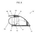
- FIG. 5 is a sectional view of camera device 100 in the first exemplary embodiment taken along line A-A.
- FIG. 5 illustrates a section taken along line A-A in FIG. 4A .
- camera body 101 configured to image a subject is supported by and covered with camera cover 102 .
- Lens portion 103 of camera body 101 is covered with lens cover 104 .
- lens cover 104 Since the edge portion of lens cover 104 is fixed to camera cover 102 while being in close contact therewith, camera body 101 including lens portion 103 is protected from hard rain, sand dust, or the like.
- Cover member 105 is attached in such a way as to surround lens cover 104 . Since guard member 105 is formed in an elliptical shape with the minor axis in the “rightward and leftward direction”, the base portion of projecting part 106 of guard member 105 is further separated from lens cover 104 than other portions (portions of guard member 105 in which projecting part 106 is not provided).
- FIG. 6A is a view illustrating the visual field of camera device 100 in the first exemplary embodiment.
- FIG. 6A illustrates a case in which camera device 100 illustrated in FIG. 2A is mounted on the side part of bus 10 in such a way that the “upward and downward direction” of camera device 100 corresponds to the upward and downward direction of bus 10 .
- Reference sign 201 represents the viewing angle of camera device 100 , which is mounted in this way, for the vicinity of the vehicle. As understood from FIG. 6A , the viewing angle is limited by projecting part 106 of guard member 105 fixed on the “outside”.
- FIG. 6B is a view illustrating the visual field of camera device 100 in the first exemplary embodiment.
- FIG. 6B illustrates a case in which camera device 100 illustrated in FIG. 2B is mounted on the rear part of bus 10 in such a way that the “upward and downward direction” of camera device 100 corresponds to the upward and downward direction of bus 10 .
- Reference sign 202 represents the viewing angle of camera device 100 , which is mounted in this way, for the vicinity of the vehicle. As understood from FIG. 6B , the viewing angle is not limited by projecting part 106 of guard member 105 fixed on the “vehicle side”.
- guard member 105 when camera device 100 is installed on the side part of bus 10 , projecting part 106 of guard member 105 is disposed further outside of lens cover 104 relative to the vehicle such that guard member 105 can protect lens cover 104 from impact against roadside trees or the like.
- guard member 105 When camera device 100 is installed on the rear part of bus 10 , projecting part 106 of guard member 105 is disposed closer to the vehicle than lens cover 104 such that the rearward visual field is not limited by guard member 105 . That is, camera device 100 can view the vicinity of the vehicle within the visual field.
- FIG. 7 is a view illustrating an example of the shape of guard member 105 in the second exemplary embodiment.
- FIG. 7 illustrates a state in which camera device 100 is mounted on the side part of bus 10 in such a way that the “upward and downward direction” of camera device 100 corresponds to the upward and downward direction of bus 10 , and the vicinity of lens cover 104 is seen from the “outside” to the “vehicle side”.
- lens cover 104 is actually hidden by projecting part 106 of guard member 105 , lens cover 104 is illustrated by the dotted line.
- Projecting part 106 of guard member 105 is formed in the shape of a gentle sloped mountain in which projecting part 106 is widened from a distal end portion to a base portion thereof such that lens cover 104 is protected.
- the width of the base portion of projecting part 106 of guard member 105 is set to be greater than that of lens cover 104 .
- the height of the distal end portion of projecting part 106 of guard member 105 is greater than that of lens cover 104 .
- Projecting part 106 of guard member 105 has a bilateral symmetrical shape when seen from the “outside” to the “vehicle side”. For this reason, even if camera device 100 is mounted on the right side part of bus 10 , it is possible to obtain the same effect.
- projecting part 106 of guard member 105 is formed in the shape of a gentle sloped mountain in which projecting part 106 is widened toward the direction of the base portion, and thus it is possible to protect lens cover 104 from impact against roadside trees or the like by guard member 105 .
- FIG. 8 is another example of a mounting state of camera device 100 in the third exemplary embodiment.
- FIG. 8 illustrates a state in which camera device 100 is mounted on the rear part of bus 10 in such a way that the “upward and downward direction” of camera device 100 corresponds to a forward and rearward direction of bus 10 .
- FIG. 9 is still another example of a mounting state of camera device 100 in the third exemplary embodiment.
- FIG. 9 illustrates a state in which camera device 100 is mounted on the rear part of bus 10 in such a way that the “upward and downward direction” of camera device 100 corresponds to a direction from the forward upper side to the rearward lower side of bus 10 .
- the “upper side” of camera device 100 is positioned on a front side of bus 10
- the “lower side” of camera device 100 is positioned on a rear side of bus 10 .
- mounted camera device 100 is formed in a streamline shape such that camera cover 102 along with projecting part 106 of guard member 105 is widened from the front side to the rear side of bus 10 .
- FIG. 10 is a view illustrating an example of the shape of guard member 105 in the third exemplary embodiment.
- the slope of streamline camera cover 102 can allow obstacle 20 such as a roadside tree to graze camera cover 102 as shown by curved arrow.
- Projecting part 106 of guard member 105 extends from streamline camera cover 102 , and projects further toward the “lower side” than lens cover 104 . For this reason, even if grazing obstacle 20 such as a roadside tree rebounds and returns its original position, lens cover 104 can be protected by projecting part 106 of guard member 105 .
- guard member 105 extends from streamline camera cover 102 , and projects further toward the “lower side” than lens cover 104 , and thus guard member 105 can protect lens cover 104 from impact against roadside trees or the like.
- guard member 105 particularly, projecting part 106 of camera device 100 described in the first exemplary embodiment is different. Duplicate portions of the description given in the first exemplary embodiment will be briefly described or omitted.
- FIG. 11 is a perspective view of camera device 300 in the fourth exemplary embodiment.
- camera device 300 is mounted on the side part of bus 10 in such a way that the “upward and downward direction” of camera device 300 corresponds to the upward and downward direction of bus 10 .
- Guard member 301 of camera device 300 has projecting part 302 for protecting lens cover 104 .
- Projecting part 302 of guard member 301 is formed in a substantially half-cylindrical shape that covers a portion of the circumference of the lens cover so as to protect lens cover 104 .
- a distal end portion and a base portion of projecting part 302 have substantially the same width. Accordingly, projecting part 302 covers a wide range of the circumference of the lens cover compared to when the projecting part 302 is formed in the shape of a gentle sloped mountain, the width of which is widened from the distal end portion to the base portion.
- a half cylinder refers to a half portion of a cylinder when the cylinder is divided by a plane including the axis.
- the sectional shape of the half cylinder sectioned by a plane that is perpendicular to the axis is a semicircular arc.
- the “substantially half-cylinder shape” of projecting part 302 may be a circular arc which is larger than (that is, a major arc) or smaller than (that is, a minor arc) a half of the full circumference.
- the radius of one circular arc of the half cylinder in an axial direction may be different from that of the other circular arc in the axial direction.
- the examples of the “substantially half cylinder” include a half elliptical cylinder, and a half cylinder that is obtained by cutting off both ends of a spheroid (which is obtained by rotating an ellipse around the major axis) in a direction along the major axis by a pair of planes that is perpendicular to the major axis in addition to a half true cylinder.
- Both circumferential ends of projecting part 302 are disposed in a state where both circumferential ends extend to the vicinities of both diametral ends of lens cover 104 .
- projecting part 302 When projecting part 302 is attached as illustrated in FIG. 11 , a left end 303 of the circumferential direction and a right end 304 of the circumferential direction are disposed remotely from lens cover 104 . That is, projecting part 302 can protect lens cover 104 in a state where lens cover 104 is remotely covered with projecting part 302 . Accordingly, guard member 301 can prevent roadside trees or the like from coming into contact with lens cover 104 .
- FIG. 12 is a perspective view of camera device 300 in the fourth exemplary embodiment.
- camera device 300 is assumably mounted on the rear part of bus 10 .
- the point of difference between camera device 300 in FIG. 12 and camera device 300 in FIG. 11 is a positional relationship between projecting part 302 of guard member 301 and bus 10 . That is, projecting part 302 of guard member 301 positioned on the “outside” in FIG. 11 is positioned on the “vehicle side” in FIG. 12 .
- FIG. 12 when camera device 300 is mounted on the rear part of bus 10 in such a way that an “upward and downward direction” of camera device 300 corresponds to the upward and downward direction of bus 10 , lens cover 104 , projecting part 302 of guard member 301 , and bus 10 are sequentially disposed from the “outside” to the “vehicle side”. In other words, projecting part 302 of guard member 301 is disposed between lens cover 104 and bus 10 .
- FIG. 13 is an exploded perspective view of camera device 300 in the fourth exemplary embodiment.
- Guard member 301 has a ring-shaped body part which is formed in a substantially circular ring shape.
- the ring-shaped body part of guard member 301 is fixed to camera cover 102 with fixing screws 108 in such a way as to surround lens cover 104 .
- Fixing screws 108 are fixed into a pair of first screw holes 305 which are provided on the circumference of camera cover 102 .
- Guard member 301 fixed as illustrated in FIG. 13 has the configuration illustrated with reference to FIG. 11 .
- Guard member 301 fixed in this state has the configuration illustrated with reference to FIG. 12 .
- projecting part 302 of guard member 301 is formed in a substantially half cylindrical shape which covers a portion of the circumference of lens cover 104 .
- projecting part 302 of guard member 301 covers almost all of the outside of lens cover 104 which is opposite to the vehicle. As a result, it is possible to better protect lens cover 104 from impact against roadside trees or the like.
- guard member 301 When camera device 300 is installed on the rear part of bus 10 , projecting part 302 of guard member 301 is disposed closer to the vehicle than lens cover 104 such that the rearward visual field is not limited by guard member 301 . That is, camera device 300 can view the vicinity of the vehicle within the visual field.
- FIG. 14 is a perspective view of camera device 300 in the fifth exemplary embodiment.
- FIG. 14 illustrates a state in which camera device 300 is mounted on the left side part of the vehicle in the forward movement direction of bus 10 in such a way that the “upward and downward direction” of camera device 300 corresponds to the forward and rearward direction of bus 10 .
- FIG. 15 is a perspective view of camera device 300 in the fifth exemplary embodiment.
- FIG. 15 illustrates a state in which camera device 300 is mounted on the right side part of the vehicle in the forward movement direction of bus 10 in such a way that the “upward and downward direction” of camera device 300 corresponds to the forward and rearward direction of bus 10 .
- FIG. 16 is an exploded perspective view of camera device 300 in the fifth exemplary embodiment.
- fixing screws 108 are fixed into a pair of second screw holes 306 which are provided on the circumference of camera cover 102 .
- guard member 301 of camera device 300 is disposed while being rotated in a clockwise direction compared to when guard member 301 is fixed via first screw holes 305 .
- the right end 304 of the circumferential direction is positioned at approximately one o'clock, and the left end 303 of the circumferential direction is positioned at approximately seven o'clock. Accordingly, the right end 304 of the circumferential direction in projecting part 302 of guard member 301 is attached in contiguity with the left side part of the vehicle in the forward movement direction of bus 10 .
- FIG. 17 is an exploded perspective view of camera device 300 in the fifth exemplary embodiment.
- fixing screws 108 are fixed into a pair of third screw holes 307 which are provided on the circumference of camera cover 102 .
- guard member 301 of camera device 300 is disposed while being rotated in a counter-clockwise direction compared to when guard member 301 is fixed via first screw holes 305 .
- the right end 304 of the circumferential direction is positioned at approximately five o'clock, and the left end 303 of the circumferential direction is positioned at approximately eleven o'clock. Accordingly, the left end 303 of the circumferential direction in projecting part 302 of guard member 301 is attached in contiguity with the right side part of the vehicle in the forward movement direction of bus 10 .
- guard member 301 can be referred to as a “rotating visor”
- one end or the other end of the circumferential direction in projecting part 302 is disposed in contiguity with bus 10 . That is, when camera device 300 is installed on the left side part of the vehicle in the forward movement direction of bus 10 , the right end 304 of the circumferential direction in projecting part 302 is disposed in contiguity with the left side part of the vehicle.
Landscapes
- Engineering & Computer Science (AREA)
- Multimedia (AREA)
- Signal Processing (AREA)
- Mechanical Engineering (AREA)
- Studio Devices (AREA)
- Camera Bodies And Camera Details Or Accessories (AREA)
- Accessories Of Cameras (AREA)
- Fittings On The Vehicle Exterior For Carrying Loads, And Devices For Holding Or Mounting Articles (AREA)
Abstract
Description
Claims (20)
Applications Claiming Priority (4)
| Application Number | Priority Date | Filing Date | Title |
|---|---|---|---|
| JP2014-237354 | 2014-11-25 | ||
| JP2014237354 | 2014-11-25 | ||
| JP2015-034919 | 2015-02-25 | ||
| JP2015034919A JP5830709B1 (en) | 2014-11-25 | 2015-02-25 | Camera device |
Publications (2)
| Publication Number | Publication Date |
|---|---|
| US20160144798A1 US20160144798A1 (en) | 2016-05-26 |
| US10027858B2 true US10027858B2 (en) | 2018-07-17 |
Family
ID=54784400
Family Applications (1)
| Application Number | Title | Priority Date | Filing Date |
|---|---|---|---|
| US14/883,992 Active US10027858B2 (en) | 2014-11-25 | 2015-10-15 | Camera device |
Country Status (2)
| Country | Link |
|---|---|
| US (1) | US10027858B2 (en) |
| JP (1) | JP5830709B1 (en) |
Families Citing this family (8)
| Publication number | Priority date | Publication date | Assignee | Title |
|---|---|---|---|---|
| DE102012024660A1 (en) * | 2012-12-17 | 2014-06-18 | Connaught Electronics Ltd. | A method of operating a camera in a covered state, camera for a motor vehicle and motor vehicle |
| DE102015117778A1 (en) * | 2015-04-30 | 2016-11-03 | Huf Hülsbeck & Fürst Gmbh & Co. Kg | Camera device for a motor vehicle |
| JP1584677S (en) * | 2016-02-02 | 2017-08-28 | ||
| US10099629B2 (en) * | 2016-09-06 | 2018-10-16 | Huf North America Automotive Parts Manufacturing Corp. | Deployable sensor assembly |
| JP6820059B2 (en) * | 2016-10-07 | 2021-01-27 | 株式会社ザクティ | Camera device |
| USD863399S1 (en) * | 2018-03-20 | 2019-10-15 | Zheng Li | Solar cell camera |
| CA188726S (en) * | 2019-01-30 | 2021-03-18 | Axis Ab | Monitoring camera |
| CN113099079A (en) * | 2021-03-04 | 2021-07-09 | 林贻富 | Prevent camera device for building of falling rocks |
Citations (4)
| Publication number | Priority date | Publication date | Assignee | Title |
|---|---|---|---|---|
| JPH08113082A (en) | 1994-10-18 | 1996-05-07 | Hino Motors Ltd | Dirt preventing device of vehicle video camera |
| US6268882B1 (en) * | 1998-12-31 | 2001-07-31 | Elbex Video Ltd. | Dome shaped camera with simplified construction and positioning |
| US20070075918A1 (en) * | 2005-04-13 | 2007-04-05 | Cuprys Lawrence M | Auxiliary targeting viewer |
| US8764318B2 (en) | 2010-06-23 | 2014-07-01 | Panasonic Corporation | Dome camera |
Family Cites Families (3)
| Publication number | Priority date | Publication date | Assignee | Title |
|---|---|---|---|---|
| JPH05338491A (en) * | 1992-06-08 | 1993-12-21 | Toshiba Corp | Movable vehicle camera device |
| JP3412757B2 (en) * | 2000-01-17 | 2003-06-03 | 株式会社アドバネット | Lens protection container |
| DE112006000936B4 (en) * | 2005-04-20 | 2011-09-15 | Autonetworks Technologies, Ltd. | Vehicle camera system |
-
2015
- 2015-02-25 JP JP2015034919A patent/JP5830709B1/en active Active
- 2015-10-15 US US14/883,992 patent/US10027858B2/en active Active
Patent Citations (4)
| Publication number | Priority date | Publication date | Assignee | Title |
|---|---|---|---|---|
| JPH08113082A (en) | 1994-10-18 | 1996-05-07 | Hino Motors Ltd | Dirt preventing device of vehicle video camera |
| US6268882B1 (en) * | 1998-12-31 | 2001-07-31 | Elbex Video Ltd. | Dome shaped camera with simplified construction and positioning |
| US20070075918A1 (en) * | 2005-04-13 | 2007-04-05 | Cuprys Lawrence M | Auxiliary targeting viewer |
| US8764318B2 (en) | 2010-06-23 | 2014-07-01 | Panasonic Corporation | Dome camera |
Also Published As
| Publication number | Publication date |
|---|---|
| JP5830709B1 (en) | 2015-12-09 |
| JP2016105149A (en) | 2016-06-09 |
| US20160144798A1 (en) | 2016-05-26 |
Similar Documents
| Publication | Publication Date | Title |
|---|---|---|
| US10027858B2 (en) | Camera device | |
| CN108696678B (en) | Camera module | |
| KR101498804B1 (en) | Mirror replacement system for a vehicle | |
| CN104321224B (en) | There is the motor vehicle of camera supervised system | |
| JP4640404B2 (en) | Vehicle driver state detection device | |
| US20200361398A1 (en) | External sensor attachment portion structure | |
| JP2016037109A (en) | Rear visual recognition device | |
| US9630568B2 (en) | Camera system for a motor vehicle | |
| JP2015076352A (en) | Headlight unit | |
| JP2013255064A (en) | Reflection reductive on-vehicle camera system | |
| WO2016092967A1 (en) | Image generation device and image generation method | |
| CN106061795A (en) | Rearward imaging device | |
| CN113966288B (en) | Rearview mirror replacement system with camera antifouling feature | |
| JP2017181634A (en) | Imaging device and in-vehicle camera system | |
| US8330815B2 (en) | Vehicle-mounted camera system | |
| JP2002325191A (en) | Surrounding monitoring device for vehicle | |
| JP2017081261A (en) | Stereo camera cover | |
| CN110861585B (en) | Arrangement structure of imaging unit for vehicle | |
| JP7063776B2 (en) | Imaging unit for vehicles | |
| EP3184370B1 (en) | Vehicle interior imaging apparatus | |
| JP7090715B2 (en) | Imaging unit for vehicles | |
| JP5807405B2 (en) | Vehicle periphery photographing device | |
| CN212484048U (en) | A detection camera assembly for automobile production line | |
| JP2018107518A (en) | Vehicle periphery monitoring device | |
| EP3620577A1 (en) | Measuring device and mobile measuring apparatus incorporating the measuring device |
Legal Events
| Date | Code | Title | Description |
|---|---|---|---|
| AS | Assignment |
Owner name: PANASONIC INTELLECTUAL PROPERTY MANAGEMENT CO., LT Free format text: ASSIGNMENT OF ASSIGNORS INTEREST;ASSIGNORS:YOSHIKUNI, YUKI;TASHIRO, HIROYUKI;KONDOU, MASAYOSHI;AND OTHERS;SIGNING DATES FROM 20150803 TO 20150818;REEL/FRAME:037094/0754 |
|
| STCF | Information on status: patent grant |
Free format text: PATENTED CASE |
|
| AS | Assignment |
Owner name: PANASONIC I-PRO SENSING SOLUTIONS CO., LTD., JAPAN Free format text: ASSIGNMENT OF ASSIGNORS INTEREST;ASSIGNOR:PANASONIC INTELLECTUAL PROPERTY MANAGEMENT CO., LTD.;REEL/FRAME:051369/0172 Effective date: 20191001 |
|
| AS | Assignment |
Owner name: PANASONIC I-PRO SENSING SOLUTIONS CO., LTD., JAPAN Free format text: CHANGE OF NAME;ASSIGNOR:PSP HOLDINGS CO., LTD;REEL/FRAME:054883/0234 Effective date: 20200401 Owner name: PSP HOLDINGS CO., LTD, JAPAN Free format text: MERGER;ASSIGNOR:PANASONIC I-PRO SENSING SOLUTIONS CO., LTD.;REEL/FRAME:054883/0201 Effective date: 20200401 Owner name: PANASONIC I-PRO SENSING SOLUTIONS CO., LTD., JAPAN Free format text: CHANGE OF ADDRESS;ASSIGNOR:PANASONIC I-PRO SENSING SOLUTIONS CO., LTD.;REEL/FRAME:054883/0248 Effective date: 20200401 |
|
| MAFP | Maintenance fee payment |
Free format text: PAYMENT OF MAINTENANCE FEE, 4TH YEAR, LARGE ENTITY (ORIGINAL EVENT CODE: M1551); ENTITY STATUS OF PATENT OWNER: LARGE ENTITY Year of fee payment: 4 |
|
| AS | Assignment |
Owner name: I-PRO CO., LTD., JAPAN Free format text: CHANGE OF NAME;ASSIGNOR:PANASONIC I-PRO SENSING SOLUTIONS CO., LTD.;REEL/FRAME:063101/0966 Effective date: 20220401 Owner name: I-PRO CO., LTD., JAPAN Free format text: CHANGE OF ADDRESS;ASSIGNOR:I-PRO CO., LTD.;REEL/FRAME:063102/0075 Effective date: 20221001 |
|
| MAFP | Maintenance fee payment |
Free format text: PAYMENT OF MAINTENANCE FEE, 8TH YEAR, LARGE ENTITY (ORIGINAL EVENT CODE: M1552); ENTITY STATUS OF PATENT OWNER: LARGE ENTITY Year of fee payment: 8 |