US10026782B2 - Implementation of VMCO area switching cell to VBL architecture - Google Patents
Implementation of VMCO area switching cell to VBL architecture Download PDFInfo
- Publication number
- US10026782B2 US10026782B2 US15/633,054 US201715633054A US10026782B2 US 10026782 B2 US10026782 B2 US 10026782B2 US 201715633054 A US201715633054 A US 201715633054A US 10026782 B2 US10026782 B2 US 10026782B2
- Authority
- US
- United States
- Prior art keywords
- layer
- memory
- word line
- bit line
- amorphous silicon
- Prior art date
- Legal status (The legal status is an assumption and is not a legal conclusion. Google has not performed a legal analysis and makes no representation as to the accuracy of the status listed.)
- Active, expires
Links
Images


Classifications
-
- H01L27/249—
-
- H—ELECTRICITY
- H10—SEMICONDUCTOR DEVICES; ELECTRIC SOLID-STATE DEVICES NOT OTHERWISE PROVIDED FOR
- H10B—ELECTRONIC MEMORY DEVICES
- H10B63/00—Resistance change memory devices, e.g. resistive RAM [ReRAM] devices
- H10B63/80—Arrangements comprising multiple bistable or multi-stable switching components of the same type on a plane parallel to the substrate, e.g. cross-point arrays
- H10B63/84—Arrangements comprising multiple bistable or multi-stable switching components of the same type on a plane parallel to the substrate, e.g. cross-point arrays arranged in a direction perpendicular to the substrate, e.g. 3D cell arrays
- H10B63/845—Arrangements comprising multiple bistable or multi-stable switching components of the same type on a plane parallel to the substrate, e.g. cross-point arrays arranged in a direction perpendicular to the substrate, e.g. 3D cell arrays the switching components being connected to a common vertical conductor
-
- G—PHYSICS
- G11—INFORMATION STORAGE
- G11C—STATIC STORES
- G11C13/00—Digital stores characterised by the use of storage elements not covered by groups G11C11/00, G11C23/00, or G11C25/00
- G11C13/0002—Digital stores characterised by the use of storage elements not covered by groups G11C11/00, G11C23/00, or G11C25/00 using resistive RAM [RRAM] elements
- G11C13/0007—Digital stores characterised by the use of storage elements not covered by groups G11C11/00, G11C23/00, or G11C25/00 using resistive RAM [RRAM] elements comprising metal oxide memory material, e.g. perovskites
-
- G—PHYSICS
- G11—INFORMATION STORAGE
- G11C—STATIC STORES
- G11C13/00—Digital stores characterised by the use of storage elements not covered by groups G11C11/00, G11C23/00, or G11C25/00
- G11C13/0002—Digital stores characterised by the use of storage elements not covered by groups G11C11/00, G11C23/00, or G11C25/00 using resistive RAM [RRAM] elements
- G11C13/0021—Auxiliary circuits
- G11C13/0023—Address circuits or decoders
- G11C13/0026—Bit-line or column circuits
-
- G—PHYSICS
- G11—INFORMATION STORAGE
- G11C—STATIC STORES
- G11C13/00—Digital stores characterised by the use of storage elements not covered by groups G11C11/00, G11C23/00, or G11C25/00
- G11C13/0002—Digital stores characterised by the use of storage elements not covered by groups G11C11/00, G11C23/00, or G11C25/00 using resistive RAM [RRAM] elements
- G11C13/0021—Auxiliary circuits
- G11C13/0023—Address circuits or decoders
- G11C13/0028—Word-line or row circuits
-
- G—PHYSICS
- G11—INFORMATION STORAGE
- G11C—STATIC STORES
- G11C13/00—Digital stores characterised by the use of storage elements not covered by groups G11C11/00, G11C23/00, or G11C25/00
- G11C13/0002—Digital stores characterised by the use of storage elements not covered by groups G11C11/00, G11C23/00, or G11C25/00 using resistive RAM [RRAM] elements
- G11C13/0021—Auxiliary circuits
- G11C13/0038—Power supply circuits
-
- G—PHYSICS
- G11—INFORMATION STORAGE
- G11C—STATIC STORES
- G11C13/00—Digital stores characterised by the use of storage elements not covered by groups G11C11/00, G11C23/00, or G11C25/00
- G11C13/0002—Digital stores characterised by the use of storage elements not covered by groups G11C11/00, G11C23/00, or G11C25/00 using resistive RAM [RRAM] elements
- G11C13/0021—Auxiliary circuits
- G11C13/004—Reading or sensing circuits or methods
-
- G—PHYSICS
- G11—INFORMATION STORAGE
- G11C—STATIC STORES
- G11C13/00—Digital stores characterised by the use of storage elements not covered by groups G11C11/00, G11C23/00, or G11C25/00
- G11C13/0002—Digital stores characterised by the use of storage elements not covered by groups G11C11/00, G11C23/00, or G11C25/00 using resistive RAM [RRAM] elements
- G11C13/0021—Auxiliary circuits
- G11C13/0069—Writing or programming circuits or methods
-
- H01L45/085—
-
- H01L45/1233—
-
- H01L45/1246—
-
- H01L45/146—
-
- H01L45/1683—
-
- H—ELECTRICITY
- H10—SEMICONDUCTOR DEVICES; ELECTRIC SOLID-STATE DEVICES NOT OTHERWISE PROVIDED FOR
- H10B—ELECTRONIC MEMORY DEVICES
- H10B63/00—Resistance change memory devices, e.g. resistive RAM [ReRAM] devices
- H10B63/20—Resistance change memory devices, e.g. resistive RAM [ReRAM] devices comprising selection components having two electrodes, e.g. diodes
- H10B63/24—Resistance change memory devices, e.g. resistive RAM [ReRAM] devices comprising selection components having two electrodes, e.g. diodes of the Ovonic threshold switching type
-
- H—ELECTRICITY
- H10—SEMICONDUCTOR DEVICES; ELECTRIC SOLID-STATE DEVICES NOT OTHERWISE PROVIDED FOR
- H10N—ELECTRIC SOLID-STATE DEVICES NOT OTHERWISE PROVIDED FOR
- H10N70/00—Solid-state devices having no potential barriers, and specially adapted for rectifying, amplifying, oscillating or switching
- H10N70/011—Manufacture or treatment of multistable switching devices
- H10N70/021—Formation of switching materials, e.g. deposition of layers
-
- H—ELECTRICITY
- H10—SEMICONDUCTOR DEVICES; ELECTRIC SOLID-STATE DEVICES NOT OTHERWISE PROVIDED FOR
- H10N—ELECTRIC SOLID-STATE DEVICES NOT OTHERWISE PROVIDED FOR
- H10N70/00—Solid-state devices having no potential barriers, and specially adapted for rectifying, amplifying, oscillating or switching
- H10N70/011—Manufacture or treatment of multistable switching devices
- H10N70/061—Shaping switching materials
- H10N70/066—Shaping switching materials by filling of openings, e.g. damascene method
-
- H—ELECTRICITY
- H10—SEMICONDUCTOR DEVICES; ELECTRIC SOLID-STATE DEVICES NOT OTHERWISE PROVIDED FOR
- H10N—ELECTRIC SOLID-STATE DEVICES NOT OTHERWISE PROVIDED FOR
- H10N70/00—Solid-state devices having no potential barriers, and specially adapted for rectifying, amplifying, oscillating or switching
- H10N70/20—Multistable switching devices, e.g. memristors
- H10N70/24—Multistable switching devices, e.g. memristors based on migration or redistribution of ionic species, e.g. anions, vacancies
- H10N70/245—Multistable switching devices, e.g. memristors based on migration or redistribution of ionic species, e.g. anions, vacancies the species being metal cations, e.g. programmable metallization cells
-
- H—ELECTRICITY
- H10—SEMICONDUCTOR DEVICES; ELECTRIC SOLID-STATE DEVICES NOT OTHERWISE PROVIDED FOR
- H10N—ELECTRIC SOLID-STATE DEVICES NOT OTHERWISE PROVIDED FOR
- H10N70/00—Solid-state devices having no potential barriers, and specially adapted for rectifying, amplifying, oscillating or switching
- H10N70/801—Constructional details of multistable switching devices
- H10N70/821—Device geometry
- H10N70/823—Device geometry adapted for essentially horizontal current flow, e.g. bridge type devices
-
- H—ELECTRICITY
- H10—SEMICONDUCTOR DEVICES; ELECTRIC SOLID-STATE DEVICES NOT OTHERWISE PROVIDED FOR
- H10N—ELECTRIC SOLID-STATE DEVICES NOT OTHERWISE PROVIDED FOR
- H10N70/00—Solid-state devices having no potential barriers, and specially adapted for rectifying, amplifying, oscillating or switching
- H10N70/801—Constructional details of multistable switching devices
- H10N70/821—Device geometry
- H10N70/826—Device geometry adapted for essentially vertical current flow, e.g. sandwich or pillar type devices
- H10N70/8265—Device geometry adapted for essentially vertical current flow, e.g. sandwich or pillar type devices on sidewalls of dielectric structures, e.g. mesa-shaped or cup-shaped devices
-
- H—ELECTRICITY
- H10—SEMICONDUCTOR DEVICES; ELECTRIC SOLID-STATE DEVICES NOT OTHERWISE PROVIDED FOR
- H10N—ELECTRIC SOLID-STATE DEVICES NOT OTHERWISE PROVIDED FOR
- H10N70/00—Solid-state devices having no potential barriers, and specially adapted for rectifying, amplifying, oscillating or switching
- H10N70/801—Constructional details of multistable switching devices
- H10N70/821—Device geometry
- H10N70/828—Current flow limiting means within the switching material region, e.g. constrictions
-
- H—ELECTRICITY
- H10—SEMICONDUCTOR DEVICES; ELECTRIC SOLID-STATE DEVICES NOT OTHERWISE PROVIDED FOR
- H10N—ELECTRIC SOLID-STATE DEVICES NOT OTHERWISE PROVIDED FOR
- H10N70/00—Solid-state devices having no potential barriers, and specially adapted for rectifying, amplifying, oscillating or switching
- H10N70/801—Constructional details of multistable switching devices
- H10N70/841—Electrodes
-
- H—ELECTRICITY
- H10—SEMICONDUCTOR DEVICES; ELECTRIC SOLID-STATE DEVICES NOT OTHERWISE PROVIDED FOR
- H10N—ELECTRIC SOLID-STATE DEVICES NOT OTHERWISE PROVIDED FOR
- H10N70/00—Solid-state devices having no potential barriers, and specially adapted for rectifying, amplifying, oscillating or switching
- H10N70/801—Constructional details of multistable switching devices
- H10N70/881—Switching materials
- H10N70/882—Compounds of sulfur, selenium or tellurium, e.g. chalcogenides
-
- H—ELECTRICITY
- H10—SEMICONDUCTOR DEVICES; ELECTRIC SOLID-STATE DEVICES NOT OTHERWISE PROVIDED FOR
- H10N—ELECTRIC SOLID-STATE DEVICES NOT OTHERWISE PROVIDED FOR
- H10N70/00—Solid-state devices having no potential barriers, and specially adapted for rectifying, amplifying, oscillating or switching
- H10N70/801—Constructional details of multistable switching devices
- H10N70/881—Switching materials
- H10N70/883—Oxides or nitrides
- H10N70/8833—Binary metal oxides, e.g. TaOx
-
- H—ELECTRICITY
- H10—SEMICONDUCTOR DEVICES; ELECTRIC SOLID-STATE DEVICES NOT OTHERWISE PROVIDED FOR
- H10W—GENERIC PACKAGES, INTERCONNECTIONS, CONNECTORS OR OTHER CONSTRUCTIONAL DETAILS OF DEVICES COVERED BY CLASS H10
- H10W20/00—Interconnections in chips, wafers or substrates
- H10W20/40—Interconnections external to wafers or substrates, e.g. back-end-of-line [BEOL] metallisations or vias connecting to gate electrodes
- H10W20/41—Interconnections external to wafers or substrates, e.g. back-end-of-line [BEOL] metallisations or vias connecting to gate electrodes characterised by their conductive parts
- H10W20/43—Layouts of interconnections
-
- H—ELECTRICITY
- H10—SEMICONDUCTOR DEVICES; ELECTRIC SOLID-STATE DEVICES NOT OTHERWISE PROVIDED FOR
- H10W—GENERIC PACKAGES, INTERCONNECTIONS, CONNECTORS OR OTHER CONSTRUCTIONAL DETAILS OF DEVICES COVERED BY CLASS H10
- H10W20/00—Interconnections in chips, wafers or substrates
- H10W20/40—Interconnections external to wafers or substrates, e.g. back-end-of-line [BEOL] metallisations or vias connecting to gate electrodes
- H10W20/41—Interconnections external to wafers or substrates, e.g. back-end-of-line [BEOL] metallisations or vias connecting to gate electrodes characterised by their conductive parts
- H10W20/44—Conductive materials thereof
- H10W20/4403—Conductive materials thereof based on metals, e.g. alloys, metal silicides
- H10W20/4437—Conductive materials thereof based on metals, e.g. alloys, metal silicides the principal metal being a transition metal
- H10W20/4441—Conductive materials thereof based on metals, e.g. alloys, metal silicides the principal metal being a transition metal the principal metal being a refractory metal
-
- G—PHYSICS
- G11—INFORMATION STORAGE
- G11C—STATIC STORES
- G11C13/00—Digital stores characterised by the use of storage elements not covered by groups G11C11/00, G11C23/00, or G11C25/00
- G11C13/0002—Digital stores characterised by the use of storage elements not covered by groups G11C11/00, G11C23/00, or G11C25/00 using resistive RAM [RRAM] elements
- G11C13/0009—RRAM elements whose operation depends upon chemical change
- G11C13/0011—RRAM elements whose operation depends upon chemical change comprising conductive bridging RAM [CBRAM] or programming metallization cells [PMCs]
-
- G—PHYSICS
- G11—INFORMATION STORAGE
- G11C—STATIC STORES
- G11C2213/00—Indexing scheme relating to G11C13/00 for features not covered by this group
- G11C2213/30—Resistive cell, memory material aspects
- G11C2213/32—Material having simple binary metal oxide structure
-
- G—PHYSICS
- G11—INFORMATION STORAGE
- G11C—STATIC STORES
- G11C2213/00—Indexing scheme relating to G11C13/00 for features not covered by this group
- G11C2213/50—Resistive cell structure aspects
- G11C2213/51—Structure including a barrier layer preventing or limiting migration, diffusion of ions or charges or formation of electrolytes near an electrode
-
- G—PHYSICS
- G11—INFORMATION STORAGE
- G11C—STATIC STORES
- G11C2213/00—Indexing scheme relating to G11C13/00 for features not covered by this group
- G11C2213/70—Resistive array aspects
- G11C2213/71—Three dimensional array
-
- G—PHYSICS
- G11—INFORMATION STORAGE
- G11C—STATIC STORES
- G11C2213/00—Indexing scheme relating to G11C13/00 for features not covered by this group
- G11C2213/70—Resistive array aspects
- G11C2213/72—Array wherein the access device being a diode
-
- G—PHYSICS
- G11—INFORMATION STORAGE
- G11C—STATIC STORES
- G11C2213/00—Indexing scheme relating to G11C13/00 for features not covered by this group
- G11C2213/70—Resistive array aspects
- G11C2213/79—Array wherein the access device being a transistor
-
- H—ELECTRICITY
- H10—SEMICONDUCTOR DEVICES; ELECTRIC SOLID-STATE DEVICES NOT OTHERWISE PROVIDED FOR
- H10B—ELECTRONIC MEMORY DEVICES
- H10B63/00—Resistance change memory devices, e.g. resistive RAM [ReRAM] devices
- H10B63/30—Resistance change memory devices, e.g. resistive RAM [ReRAM] devices comprising selection components having three or more electrodes, e.g. transistors
- H10B63/34—Resistance change memory devices, e.g. resistive RAM [ReRAM] devices comprising selection components having three or more electrodes, e.g. transistors of the vertical channel field-effect transistor type
-
- H—ELECTRICITY
- H10—SEMICONDUCTOR DEVICES; ELECTRIC SOLID-STATE DEVICES NOT OTHERWISE PROVIDED FOR
- H10D—INORGANIC ELECTRIC SEMICONDUCTOR DEVICES
- H10D30/00—Field-effect transistors [FET]
- H10D30/60—Insulated-gate field-effect transistors [IGFET]
- H10D30/67—Thin-film transistors [TFT]
- H10D30/6728—Vertical TFTs
-
- H—ELECTRICITY
- H10—SEMICONDUCTOR DEVICES; ELECTRIC SOLID-STATE DEVICES NOT OTHERWISE PROVIDED FOR
- H10D—INORGANIC ELECTRIC SEMICONDUCTOR DEVICES
- H10D86/00—Integrated devices formed in or on insulating or conducting substrates, e.g. formed in silicon-on-insulator [SOI] substrates or on stainless steel or glass substrates
- H10D86/40—Integrated devices formed in or on insulating or conducting substrates, e.g. formed in silicon-on-insulator [SOI] substrates or on stainless steel or glass substrates characterised by multiple TFTs
- H10D86/60—Integrated devices formed in or on insulating or conducting substrates, e.g. formed in silicon-on-insulator [SOI] substrates or on stainless steel or glass substrates characterised by multiple TFTs wherein the TFTs are in active matrices
Definitions
- Semiconductor memory is widely used in various electronic devices such as mobile computing devices, mobile phones, solid-state drives, digital cameras, personal digital assistants, medical electronics, servers, and non-mobile computing devices.
- Semiconductor memory may comprise non-volatile memory or volatile memory.
- a non-volatile memory device allows information to be stored or retained even when the non-volatile memory device is not connected to a source of power (e.g., a battery).
- non-volatile memory examples include flash memory (e.g., NAND-type and NOR-type flash memory), Electrically Erasable Programmable Read-Only Memory (EEPROM), ferroelectric memory (e.g., FeRAM), magnetoresistive memory (e.g., MRAM), and phase change memory (e.g., PRAM).
- flash memory e.g., NAND-type and NOR-type flash memory
- EEPROM Electrically Erasable Programmable Read-Only Memory
- FeRAM ferroelectric memory
- MRAM magnetoresistive memory
- PRAM phase change memory
- FIGS. 2A-2B depict various embodiments of a portion of a three-dimensional memory array.
- FIG. 6 depicts a cross-sectional view of a memory structure with vertical bit lines.
- FIGS. 7A-7L depict various embodiments of processes for forming portions of a memory array.
- FIGS. 8A-8B depict flowcharts describing embodiments of processes for forming portions of a memory array.
- VMCO structures may be partially or fully embedded within word line layers of a memory array, such as a memory array arranged using a VBL architecture (e.g., a memory array architecture in which memory cells are arranged between horizontal word lines and vertical bit lines that are orthogonal to a substrate).
- a VMCO structure may be partially or fully formed within a word line layer of a memory array.
- a VMCO stack may comprise a layer of amorphous silicon and a layer titanium oxide. In some cases, the VMCO stack may comprise a layer of thin aluminum oxide or other metal oxides arranged between the layer of amorphous silicon and the layer titanium oxide.
- the thickness of the VMCO layers required for reliable memory cell switching may limit the ability to scale or shrink the memory array (e.g., the layer of amorphous silicon may have to be at least 10 nm and/or the layer of titanium oxide may have to be at least 10 nm).
- the layer of amorphous silicon may have to be at least 10 nm and/or the layer of titanium oxide may have to be at least 10 nm.
- Partially or fully embedding a VMCO structure (or other memory cell switching structure, such as a ReRAM material structure or a phase change material structure) into a recessed portion of a word line layer may allow for a reduction in die area and may improve the reliability of the memory cell structures (by providing improved isolation between VMCO structures).
- amorphous silicon and titanium oxide may also be used.
- the layer of amorphous silicon may be replaced with a layer of hafnium oxide or other high-k dielectrics that are characterized by a high barrier height and the layer of titanium oxide may be replaced with a layer of tungsten oxide, tantalum oxide, or other lower barrier height dielectrics.
- a layer of thin aluminum oxide and other high-k dielectrics may be arranged between the layer of amorphous silicon and the layer of titanium oxide.
- a memory array may comprise a cross-point memory array.
- a cross-point memory array may refer to a memory array in which two-terminal memory cells are placed at the intersections of a first set of control lines (e.g., word lines) arranged in a first direction and a second set of control lines (e.g., bit lines) arranged in a second direction perpendicular to the first direction.
- the two-terminal memory cells may include a resistance-switching material, such as a phase change material, a ferroelectric material, or a metal oxide (e.g., nickel oxide or hafnium oxide).
- each memory cell in a cross-point memory array may be placed in series with a steering element or an isolation element, such as a diode, in order to reduce leakage currents.
- a steering element or an isolation element such as a diode
- controlling and minimizing leakage currents may be a significant issue, especially since leakage currents may vary greatly over biasing voltage and temperature.
- a non-volatile storage system may include one or more two-dimensional arrays of non-volatile memory cells.
- the memory cells within a two-dimensional memory array may form a single layer of memory cells and may be selected via control lines (e.g., word lines and bit lines) in the X and Y directions.
- a non-volatile storage system may include one or more monolithic three-dimensional memory arrays in which two or more layers of memory cells may be formed above a single substrate without any intervening substrates.
- a three-dimensional memory array may include one or more vertical columns of memory cells located above and orthogonal to a substrate.
- a non-volatile storage system may include a memory array with vertical bit lines or bit lines that are arranged orthogonal to a semiconductor substrate.
- the substrate may comprise a silicon substrate.
- the memory array may include rewriteable non-volatile memory cells, wherein each memory cell includes a reversible resistance-switching element without an isolation element in series with the reversible resistance-switching element (e.g., no diode in series with the reversible resistance-switching element).
- a non-volatile storage system may include a monolithic three-dimensional memory array.
- the monolithic three-dimensional memory array may include one or more levels of memory cells.
- Each memory cell within a first level of the one or more levels of memory cells may include an active area that is located above a substrate (e.g., a single-crystal substrate or a crystalline silicon substrate).
- the active area may include a semiconductor junction (e.g., a P-N junction).
- the active area may include a portion of a source or drain region of a transistor.
- the active area may include a channel region of a transistor.
- the memory cells within a memory array may comprise re-writable non-volatile memory cells including a reversible resistance-switching element.
- a reversible resistance-switching element may include a reversible resistivity-switching material having a resistivity that may be reversibly switched between two or more states.
- the reversible resistance-switching material may include a metal oxide (e.g., a binary metal oxide).
- the metal oxide may include nickel oxide or hafnium oxide.
- the reversible resistance-switching material may include a phase change material.
- the phase change material may include a chalcogenide material.
- the re-writeable non-volatile memory cells may comprise resistive RAM (ReRAM) memory cells.
- the re-writeable non-volatile memory cells may comprise conductive bridge memory cells or programmable metallization memory cells.
- FIG. 1A depicts one embodiment of a memory system 101 and a host 106 .
- the memory system 101 may comprise a non-volatile storage system interfacing with the host (e.g., a mobile computing device or a server). In some cases, the memory system 101 may be embedded within the host 106 .
- the memory system 101 may comprise a memory card, a solid-state drive (SSD) such a high density MLC SSD (e.g., 2-bits/cell or 3-bits/cell) or a high performance SLC SSD, or a hybrid HDD/SSD drive.
- SSD solid-state drive
- the memory system 101 includes a memory chip controller 105 and a memory chip 102 .
- the memory chip 102 may include volatile memory and/or non-volatile memory.
- the memory system 101 may include more than one memory chip (e.g., four or eight memory chips).
- the memory chip controller 105 may receive data and commands from host 106 and provide memory chip data to host 106 .
- the memory chip controller 105 may include one or more state machines, page registers, SRAM, and control circuitry for controlling the operation of memory chip 102 .
- the one or more state machines, page registers, SRAM, and control circuitry for controlling the operation of the memory chip may be referred to as managing or control circuits.
- the managing or control circuits may facilitate one or more memory array operations including forming, erasing, programming, or reading operations.
- the managing or control circuits (or a portion of the managing or control circuits) for facilitating one or more memory array operations may be integrated within the memory chip 102 .
- the memory chip controller 105 and memory chip 102 may be arranged on a single integrated circuit or arranged on a single die. In other embodiments, the memory chip controller 105 and memory chip 102 may be arranged on different integrated circuits. In some cases, the memory chip controller 105 and memory chip 102 may be integrated on a system board, logic board, or a PCB.
- the memory chip 102 includes memory core control circuits 104 and a memory core 103 .
- Memory core control circuits 104 may include logic for controlling the selection of memory blocks (or arrays) within memory core 103 , controlling the generation of voltage references for biasing a particular memory array into a read or write state, and generating row and column addresses.
- the memory core 103 may include one or more two-dimensional arrays of memory cells or one or more three-dimensional arrays of memory cells.
- the memory core control circuits 104 and memory core 103 may be arranged on a single integrated circuit. In other embodiments, the memory core control circuits 104 (or a portion of the memory core control circuits) and memory core 103 may be arranged on different integrated circuits.
- a memory operation may be initiated when host 106 sends instructions to memory chip controller 105 indicating that it would like to read data from memory system 101 or write data to memory system 101 .
- host 106 may send to memory chip controller 105 both a write command and the data to be written.
- the data to be written may be buffered by memory chip controller 105 and error correcting code (ECC) data may be generated corresponding with the data to be written.
- ECC error correcting code
- the ECC data which allows data errors that occur during transmission or storage to be detected and/or corrected, may be written to memory core 103 or stored in non-volatile memory within memory chip controller 105 .
- the ECC data is generated and data errors are corrected by circuitry within memory chip controller 105 .
- one or more managing or control circuits may be used for controlling the operation of a memory array within the memory core 103 .
- the one or more managing or control circuits may provide control signals to a memory array in order to perform a read operation and/or a write operation on the memory array.
- the one or more managing or control circuits may include any one of or a combination of control circuitry, state machines, decoders, sense amplifiers, read/write circuits, and/or controllers.
- the one or more managing circuits may perform or facilitate one or more memory array operations including erasing, programming, or reading operations.
- one or more managing circuits may comprise an on-chip memory controller for determining row and column address, word line and bit line addresses, memory array enable signals, and data latching signals.
- FIG. 1B depicts one embodiment of memory core control circuits 104 .
- the memory core control circuits 104 include address decoders 170 , voltage generators for selected control lines 172 , and voltage generators for unselected control lines 174 .
- Control lines may include word lines, bit lines, or a combination of word lines and bit lines.
- Selected control lines may include selected word lines or selected bit lines that are used to place memory cells into a selected state.
- Unselected control lines may include unselected word lines or unselected bit lines that are used to place memory cells into an unselected state.
- the voltage generators (or voltage regulators) for selected control lines 172 may comprise one or more voltage generators for generating selected control line voltages.
- the voltage generators for unselected control lines 174 may comprise one or more voltage generators for generating unselected control line voltages.
- Address decoders 170 may generate memory block addresses, as well as row addresses and column addresses for a particular memory block.
- the memory system 101 may perform a read-before-write (RBW) operation to read the data currently stored at the target address before performing a write operation to write the set of data to the target address.
- the memory system 101 may then determine whether a particular memory cell may stay at its current state (i.e., the memory cell is already at the correct state), needs to be set to a “0” state, or needs to be reset to a “1” state.
- the memory system 101 may then write a first subset of the memory cells to the “0” state and then write a second subset of the memory cells to the “1” state.
- the memory cells that are already at the correct state may be skipped over, thereby improving programming speed and reducing the cumulative voltage stress applied to unselected memory cells.
- read/write circuits 306 may be used to program a particular memory cell to be in one of three or more data/resistance states (i.e., the particular memory cell may comprise a multi-level memory cell).
- the read/write circuits 306 may apply a first voltage difference (e.g., 2V) across the particular memory cell to program the particular memory cell into a first state of the three or more data/resistance states or a second voltage difference (e.g., 1V) across the particular memory cell that is less than the first voltage difference to program the particular memory cell into a second state of the three or more data/resistance states.
- a first voltage difference e.g., 2V
- a second voltage difference e.g., 1V
- Applying a smaller voltage difference across the particular memory cell may cause the particular memory cell to be partially programmed or programmed at a slower rate than when applying a larger voltage difference.
- the read/write circuits 306 may apply a first voltage difference across the particular memory cell for a first time period (e.g., 150 ns) to program the particular memory cell into a first state of the three or more data/resistance states or apply the first voltage difference across the particular memory cell for a second time period less than the first time period (e.g., 50 ns).
- One or more programming pulses followed by a memory cell verification phase may be used to program the particular memory cell to be in the correct state.
- FIG. 1E depicts one embodiment of memory block 310 in FIG. 1D .
- memory block 310 includes a memory array 301 , row decoder 304 , and column decoder 302 .
- Memory array 301 may comprise a contiguous group of memory cells having contiguous word lines and bit lines.
- Memory array 301 may comprise one or more layers of memory cells.
- Memory array 310 may comprise a two-dimensional memory array or a three-dimensional memory array.
- the row decoder 304 decodes a row address and selects a particular word line in memory array 301 when appropriate (e.g., when reading or writing memory cells in memory array 301 ).
- FIG. 1F depicts one embodiment of a memory bay 332 .
- Memory bay 332 is one example of an alternative implementation for memory bay 330 in FIG. 1D .
- row decoders, column decoders, and read/write circuits may be split or shared between memory arrays.
- row decoder 349 is shared between memory arrays 352 and 354 because row decoder 349 controls word lines in both memory arrays 352 and 354 (i.e., the word lines driven by row decoder 349 are shared).
- Row decoders 348 and 349 may be split such that even word lines in memory array 352 are driven by row decoder 348 and odd word lines in memory array 352 are driven by row decoder 349 .
- FIG. 1G depicts one embodiment of a schematic diagram (including word lines and bit lines) corresponding with memory bay 332 in FIG. 1F .
- word lines WL 1 , WL 3 , and WL 5 are shared between memory arrays 352 and 354 and controlled by row decoder 349 of FIG. 1F .
- Word lines WL 0 , WL 2 , WL 4 , and WL 6 are driven from the left side of memory array 352 and controlled by row decoder 348 of FIG. 1F .
- Word lines WL 14 , WL 16 , WL 18 , and WL 20 are driven from the right side of memory array 354 and controlled by row decoder 350 of FIG. 1F .
- the memory arrays 352 and 354 may comprise memory layers that are oriented in a horizontal plane that is horizontal to the supporting substrate. In another embodiment, the memory arrays 352 and 354 may comprise memory layers that are oriented in a vertical plane that is vertical with respect to the supporting substrate (i.e., the vertical plane is perpendicular to the supporting substrate). In this case, the bit lines of the memory arrays may comprise vertical bit lines.
- the diodes of the first memory level 218 may be upward pointing diodes as indicated by arrow A 1 (e.g., with p regions at the bottom of the diodes), while the diodes of the second memory level 220 may be downward pointing diodes as indicated by arrow A 2 (e.g., with n regions at the bottom of the diodes), or vice versa.
- each memory cell includes a state change element and does not include a steering element. The absence of a diode (or other steering element) from a memory cell may reduce the process complexity and costs associated with manufacturing a memory array.
- the memory cells 200 of FIG. 2A may comprise re-writable non-volatile memory cells including a reversible resistance-switching element.
- a reversible resistance-switching element may include a reversible resistivity-switching material having a resistivity that may be reversibly switched between two or more states.
- the reversible resistance-switching material may include a metal oxide (e.g., a binary metal oxide).
- the metal oxide may include nickel oxide or hafnium oxide.
- the reversible resistance-switching material may include a phase change material.
- the phase change material may include a chalcogenide material.
- the re-writeable non-volatile memory cells may comprise resistive RAM (ReRAM) devices.
- ReRAM resistive RAM
- the memory cells 200 of FIG. 2A may include conductive bridge memory elements.
- a conductive bridge memory element may also be referred to as a programmable metallization cell.
- a conductive bridge memory element may be used as a state change element based on the physical relocation of ions within a solid electrolyte.
- a conductive bridge memory element may include two solid metal electrodes, one relatively inert (e.g., tungsten) and the other electrochemically active (e.g., silver or copper), with a thin film of the solid electrolyte between the two electrodes.
- the conductive bridge memory element may have a wide range of programming thresholds over temperature.
- the data stored in one of the plurality of memory cells 200 may be read by biasing one of the word lines (i.e., the selected word line) to a selected word line voltage in read mode (e.g., 0V).
- a read circuit may then be used to bias a selected bit line connected to the selected memory cell to the selected bit line voltage in read mode (e.g., 1.0V).
- the unselected word lines may be biased to the same voltage as the selected bit lines (e.g., 1.0V).
- both the unselected word lines and the unselected bit lines may be biased to an intermediate voltage that is between the selected word line voltage and the selected bit line voltage. Applying the same voltage to both the unselected word lines and the unselected bit lines may reduce the voltage stress across the unselected memory cells driven by both the unselected word lines and the unselected bit lines; however, the reduced voltage stress comes at the expense of increased leakage currents associated with the selected word line and the selected bit line.
- the selected bit line voltage may be applied to the selected bit line, and a read circuit may then sense an auto zero amount of current through the selected memory bit line which is subtracted from the bit line current in a second current sensing when the selected word line voltage is applied to the selected word line.
- the leakage current may be subtracted out by using the auto zero current sensing.
- the reversible resistance-switching material may be in an initial high-resistivity state that is switchable to a low-resistivity state upon application of a first voltage and/or current. Application of a second voltage and/or current may return the reversible resistance-switching material back to the high-resistivity state.
- the reversible resistance-switching material may be in an initial low-resistance state that is reversibly switchable to a high-resistance state upon application of the appropriate voltage(s) and/or current(s).
- one resistance state When used in a memory cell, one resistance state may represent a binary data “0” while another resistance state may represent a binary data “1.”
- a memory cell When used in a memory cell, one resistance state may represent a binary data “0” while another resistance state may represent a binary data “1.”
- a memory cell may be considered to comprise more than two data/resistance states (i.e., a multi-level memory cell).
- a write operation may be similar to a read operation except with a larger voltage range placed across the selected memory cells.
- the process of switching the resistance of a reversible resistance-switching element from a high-resistivity state to a low-resistivity state may be referred to as SETTING the reversible resistance-switching element.
- the process of switching the resistance from the low-resistivity state to the high-resistivity state may be referred to as RESETTING the reversible resistance-switching element.
- the high-resistivity state may be associated with binary data “1” and the low-resistivity state may be associated with binary data “0.” In other embodiments, SETTING and RESETTING operations and/or the data encoding may be reversed.
- the high-resistivity state may be associated with binary data “0” and the low-resistivity state may be associated with binary data “1.”
- a higher than normal programming voltage may be required the first time a reversible resistance-switching element is SET into the low-resistivity state as the reversible resistance-switching element may have been placed into a resistance state that is higher than the high-resistivity state when fabricated.
- the term “FORMING” may refer to the setting of a reversible resistance-switching element into a low-resistivity state for the first time after fabrication or the resetting of a reversible resistance-switching element into a high-resistivity state for the first time after fabrication.
- the reversible resistance-switching element may be RESET to the high-resistivity state and then SET again to the low-resistivity state.
- data may be written to one of the plurality of memory cells 200 by biasing one of the word lines (i.e., the selected word line) to the selected word line voltage in write mode (e.g., 5V).
- a write circuit may be used to bias the bit line connected to the selected memory cell to the selected bit line voltage in write mode (e.g., 0V).
- the unselected bit lines may be biased such that a first voltage difference between the selected word line voltage and the unselected bit line voltage is less than a first disturb threshold.
- the unselected word lines may be biased such that a second voltage difference between the unselected word line voltage and the selected bit line voltage is less than a second disturb threshold.
- the first disturb threshold and the second disturb threshold may be different depending on the amount of time in which the unselected memory cells susceptible to disturb are stressed.
- both the unselected word lines and the unselected bit lines may be biased to an intermediate voltage that is between the selected word line voltage and the selected bit line voltage.
- the intermediate voltage may be generated such that a first voltage difference across unselected memory cells sharing a selected word line is greater than a second voltage difference across other unselected memory cells sharing a selected bit line.
- One reason for placing the larger voltage difference across the unselected memory cells sharing a selected word line is that the memory cells sharing the selected word line may be verified immediately after a write operation in order to detect a write disturb.
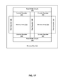
- FIG. 2B depicts a subset of the memory array and routing layers of one embodiment of a three-dimensional memory array, such as memory array 301 in FIG. 1E .
- the Memory Array layers are positioned above the Substrate.
- the Memory Array layers include bit line layers BL 0 , BL 1 and BL 2 , and word line layers WL 0 and WL 1 . In other embodiments, additional bit line and word line layers can also be implemented.
- Supporting circuitry e.g., row decoders, column decoders, and read/write circuits
- An integrated circuit implementing a three-dimensional memory array may also include multiple metal layers for routing signals between different components of the supporting circuitry, and between the supporting circuitry and the bit lines and word lines of the memory array. These routing layers can be arranged above the supporting circuitry that is implemented on the surface of the Substrate and below the Memory Array layers.
- two metal layers R 1 and R 2 may be used for routing layers; however, other embodiments can include more or less than two metal layers.
- these metal layers R 1 and R 2 may be formed of tungsten (about 1 ohm/square).
- Positioned above the Memory Array layers may be one or more top metal layers used for routing signals between different components of the integrated circuit, such as the Top Metal layer.
- the Top Metal layer is formed of copper or aluminum (about 0.05 ohms/square), which may provide a smaller resistance per unit area than metal layers R 1 and R 2 .
- FIG. 3A depicts one embodiment of a cross-point memory array 360 .
- the cross-point memory array 360 may correspond with memory array 201 in FIG. 2A .
- cross-point memory array 360 includes word lines 365 - 368 and bit lines 361 - 364 .
- the bit lines 361 may comprise vertical bit lines or horizontal bit lines.
- Word line 366 comprises a selected word line and bit line 362 comprises a selected bit line.
- S cell select memory cell
- the voltage across the S cell is the difference between the selected word line voltage and the selected bit line voltage.
- Memory cells at the intersections of the selected word line 366 and the unselected bit lines 361 , 363 , and 364 comprise unselected memory cells (H cells).
- H cells are unselected memory cells that share a selected word line that is biased to the selected word line voltage. The voltage across the H cells is the difference between the selected word line voltage and the unselected bit line voltage.
- Memory cells at the intersections of the selected bit line 362 and the unselected word lines 365 , 367 , and 368 comprise unselected memory cells (F cells).
- F cells are unselected memory cells that share a selected bit line that is biased to a selected bit line voltage. The voltage across the F cells is the difference between the unselected word line voltage and the selected bit line voltage.
- Memory cells at the intersections of the unselected word lines 365 , 367 , and 368 and the unselected bit lines 361 , 363 , and 364 comprise unselected memory cells (U cells).
- the voltage across the U cells is the difference between the unselected word line voltage and the unselected bit line voltage.
- the number of F cells is related to the length of the bit lines (or the number of memory cells connected to a bit line) while the number of H cells is related to the length of the word lines (or the number of memory cells connected to a word line).
- the number of U cells is related to the product of the word line length and the bit line length.
- each memory cell sharing a particular word line such as word line 365 , may be associated with a particular page stored within the cross-point memory array 360 .
- FIG. 3B depicts an alternative embodiment of a cross-point memory array 370 .
- the cross-point memory array 370 may correspond with memory array 201 in FIG. 2A .
- cross-point memory array 370 includes word lines 375 - 378 and bit lines 371 - 374 .
- the bit lines 361 may comprise vertical bit lines or horizontal bit lines.
- Word line 376 comprises a selected word line and bit lines 372 and 374 comprise selected bit lines. Although both bit lines 372 and 374 are selected, the voltages applied to bit line 372 and bit line 374 may be different.
- bit line 372 may be biased to a selected bit line voltage in order to program the first memory cell.
- bit line 374 may be biased to a program inhibit voltage (i.e., to a bit line voltage that will prevent the second memory cell from being programmed).
- a program inhibited memory cell At the intersection of selected word line 376 and selected bit line 374 is a program inhibited memory cell (an I cell).
- the voltage across the I cell is the difference between the selected word line voltage and the program inhibit voltage.
- Memory cells at the intersections of the selected bit line 374 and the unselected word lines 375 , 377 , and 378 comprise unselected memory cells (X cells).
- X cells are unselected memory cells that share a selected bit line that is biased to a program inhibit voltage.
- the voltage across the X cells is the difference between the unselected word line voltage and the program inhibit voltage.
- the program inhibit voltage applied to the selected bit line 374 may be the same as or substantially the same as the unselected bit line voltage.
- the program inhibit voltage may be a voltage that is greater than or less than the unselected bit line voltage.
- the program inhibit voltage may be set to a voltage that is between the selected word line voltage and the unselected bit line voltage.
- the program inhibit voltage applied may be a function of temperature.
- the program inhibit voltage may track the unselected bit line voltage over temperature.
- two or more pages may be associated with a particular word line.
- word line 375 may be associated with a first page and a second page.
- the first page may correspond with bit lines 371 and 373 and the second page may correspond with bit lines 372 and 374 .
- the first page and the second page may correspond with interdigitated memory cells that share the same word line.
- one or more other pages also associated with the selected word line 376 may comprise H cells because the memory cells associated with the one or more other pages will share the same selected word line as the first page.
- not all unselected bit lines may be driven to an unselected bit line voltage. Instead, a number of unselected bit lines may be floated and indirectly biased via the unselected word lines.
- the memory cells of memory array 370 may comprise resistive memory elements without isolating diodes.
- the bit lines 372 and 373 may comprise vertical bit lines in a three dimensional memory array comprising comb shaped word lines.
- FIG. 4A depicts one embodiment of a portion of a monolithic three-dimensional memory array 416 that includes a first memory level 412 positioned below a second memory level 410 .
- Memory array 416 is one example of an implementation for memory array 301 in FIG. 1E .
- the local bit lines LBL 11 -LBL 33 are arranged in a first direction (i.e., a vertical direction) and the word lines WL 10 -WL 23 are arranged in a second direction perpendicular to the first direction.
- This arrangement of vertical bit lines in a monolithic three-dimensional memory array is one embodiment of a vertical bit line memory array.
- each local bit line and each word line is a particular memory cell (e.g., memory cell M 111 is disposed between local bit line LBL 11 and word line WL 10 ).
- the particular memory cell may include a floating gate device or a charge trap device (e.g., using a silicon nitride material).
- the particular memory cell may include a reversible resistance-switching material, a metal oxide, a phase change material, or a ReRAM material.
- the global bit lines GBL 1 -GBL 3 are arranged in a third direction that is perpendicular to both the first direction and the second direction.
- a set of bit line select devices may be used to select a set of local bit lines (e.g., LBL 11 -LBL 31 ).
- bit line select devices Q 11 -Q 31 are used to select the local bit lines LBL 11 -LBL 31 and to connect the local bit lines LBL 11 -LBL 31 to the global bit lines GBL 1 -GBL 3 using row select line SG 1 .
- bit line select devices Q 12 -Q 32 are used to selectively connect the local bit lines LBL 12 -LBL 32 to the global bit lines GBL 1 -GBL 3 using row select line SG 2 and bit line select devices Q 13 -Q 33 are used to selectively connect the local bit lines LBL 13 -LBL 33 to the global bit lines GBL 1 -GBL 3 using row select line SG 3 .
- a first set of local bit lines e.g., LBL 11 -LBL 31
- the other local bit lines e.g., LBL 12 -LBL 32 and LBL 13 -LBL 33
- all local bit lines within the memory array are first biased to an unselected bit line voltage by connecting each of the global bit lines to one or more local bit lines.
- the one or more selected bit line voltages may correspond with, for example, one or more read voltages during a read operation or one or more programming voltages during a programming operation.
- a vertical bit line memory array such as memory array 416 , includes a greater number of memory cells along the word lines as compared with the number of memory cells along the vertical bit lines (e.g., the number of memory cells along a word line may be more than 10 times the number of memory cells along a bit line). In one example, the number of memory cells along each bit line may be 16 or 32, while the number of memory cells along each word line may be 2048 or more than 4096.
- FIG. 4B depicts one embodiment of a portion of a monolithic three-dimensional memory array that includes vertical strips of a non-volatile memory material.
- the physical structure depicted in FIG. 4B may comprise one implementation for a portion of the monolithic three-dimensional memory array depicted in FIG. 4A .
- the vertical strips of non-volatile memory material may be formed in a direction that is perpendicular to a substrate (e.g., in the Z direction).
- a vertical strip of the non-volatile memory material 414 may include, for example, a vertical oxide layer, a vertical metal oxide layer (e.g., nickel oxide or hafnium oxide), a vertical layer of phase change material, or a vertical charge trapping layer (e.g., a layer of silicon nitride).
- the vertical strip of material may comprise a single continuous layer of material that may be used by a plurality of memory cells or devices.
- portions of the vertical strip of the non-volatile memory material 414 may comprise a part of a first memory cell associated with the cross section between WL 12 and LBL 13 and a part of a second memory cell associated with the cross section between WL 22 and LBL 13 .
- a vertical bit line such as LBL 13
- LBL 13 may comprise a vertical structure (e.g., a rectangular prism, a cylinder, or a pillar) and the non-volatile material may completely or partially surround the vertical structure (e.g., a conformal layer of phase change material surrounding the sides of the vertical structure).
- each of the vertical bit lines may be connected to one of a set of global bit lines via a select transistor.
- the select transistor may comprise a MOS device (e.g., an NMOS device) or a vertical thin-film transistor (TFT).
- FIG. 5 depicts one embodiment of a read/write circuit 502 along with a portion of a memory array 501 .
- Read/write circuit 502 is one example of an implementation of read/write circuit 306 in FIG. 1D .
- the portion of a memory array 501 includes two of the many bit lines (one selected bit line labeled “Selected BL” and one unselected bit line labeled “Unselected BL”) and two of the many word lines (one selected word line labeled “Selected WL” and one unselected word line labeled “Unselected WL”).
- the portion of a memory array also includes a selected memory cell 550 and unselected memory cells 552 - 556 .
- the portion of a memory array 501 may comprise a memory array with bit lines arranged in a direction horizontal to the substrate, such as memory array 201 in FIG. 2A .
- the portion of a memory array 501 may comprise a memory array with bit lines arranged in a vertical direction that is perpendicular to the substrate, such as memory array 416 in FIG. 4A .
- the selected bit line may be biased to 1V
- the unselected word line may be biased to 0.6V
- the selected word line may be biased to 0V
- the unselected bit line may be biased to 0.5V.
- the selected bit line may be biased to a selected bit line voltage (e.g., 2.0V)
- the unselected word line may be biased to an unselected word line voltage (e.g., 1.0V)
- the selected word line may be biased to a selected word line voltage (e.g., 0V)
- the unselected bit line may be biased to an unselected bit line voltage (e.g., 1V).
- the unselected memory cells sharing the selected word line will be biased to the voltage difference between the selected word line voltage and the unselected bit line voltage.
- the memory array biasing scheme depicted in FIG. 5 may be reversed such that the selected bit line is biased to 0V, the unselected word line is biased to 0.4V, the selected word line is biased to 1V, and the unselected bit line is biased to 0.5V.
- the SELB node of read/write circuit 502 may be electrically coupled to the selected bit line via column decoder 504 .
- column decoder 504 may correspond with column decoder 302 depicted in FIG. 1E .
- Transistor 562 couples (or electrically connects) node SELB to the Vsense node.
- the transistor 562 may comprise a low VT nMOS device.
- Clamp control circuit 564 controls the gate of transistor 562 .
- the Vsense node is connected to reference current Iref and one input of sense amplifier 566 .
- the other input of sense amplifier 566 receives Vref-read, which is the voltage level used for comparing the Vsense node voltage in read mode.
- the output of sense amplifier 566 is connected to the data out terminal and to data latch 568 .
- Write circuit 560 is connected to node SELB, the Data In terminal, and data latch 568 .
- read/write circuit 502 biases the selected bit line to the selected bit line voltage in read mode. Prior to sensing data, read/write circuit 502 will precharge the Vsense node to 2V (or some other voltage greater than the selected bit line voltage). When sensing data, read/write circuit 502 attempts to regulate the SELB node to the selected bit line voltage (e.g., 1V) via clamp control circuit 564 and transistor 562 in a source-follower configuration.
- the selected bit line voltage e.g., 1V
- Vref-read e.g., set to 1.5V
- the sense amplifier 566 will read out a data “0.” Outputting a data “0” represents that the selected memory cell 550 is in a low resistance state (e.g., a SET state). If the current through the selected memory cell 550 is less than Iref, then the Vsense node will stay above Vref-read and the sense amplifier 566 will read out a data “1.” Outputting a data “1” represents that the selected memory cell 550 is in a high resistance state (e.g., a RESET state).
- Data latch 568 may latch the output of sense amplifier 566 after a time period of sensing the current through the selected memory cell (e.g., after 400 ns).
- read/write circuit 502 may bias SELB to the selected bit line voltage for programming a data “0” in write mode (e.g., 1.2V for a SET operation) via write circuit 560 .
- the duration of programming the memory cell may be a fixed time period (e.g., using a fixed-width programming pulse) or variable (e.g., using a write circuit 560 that senses whether a memory cell has been programmed while programming).
- read/write circuit 502 may bias SELB to the selected bit line voltage for programming a data “1” in write mode (e.g., 0V or ⁇ 1.2V for a RESET operation) via write circuit 560 .
- write circuit 560 may bias SELB to a program inhibit voltage during write mode.
- the program inhibit voltage may be the same as or close to the unselected bit line voltage.
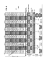
- FIG. 6 depicts a cross-sectional view of a memory structure using the vertically oriented select devices shown in FIG. 4B .
- the memory structure of FIG. 6 may comprise a continuous mesh array of memory elements because there are memory elements connected to both sides of the bit lines and memory elements connected to both sides of the word lines.
- a silicon substrate is depicted.
- various metal lines including ML- 0 , ML- 1 , and ML- 2 .
- Line 526 of ML- 2 serves as a respective global bit line (GBL).
- the Pillar Select Layer includes two oxide layers 520 with a gate material layer 522 sandwiched there between.
- the oxide layers 520 can be SiO 2 .
- the metal line ML- 2 526 serving as a global bit line can be implemented of any suitable material, including Tungsten, or Tungsten on a Titanium Nitride adhesion layer or a sandwich of n+ polysilicon on Tungsten on Titanium Nitride adhesion layer.
- Gate material 522 can be polysilicon, Titanium Nitride, Tantalum Nitride, Nickel Silicide or any other suitable material.
- Gate material 522 implements the row select lines SG x (e.g. SG 1 , SG 2 , . . . of FIG. 4B ), which are labeled in FIG. 6 as row select lines 580 , 582 , 584 , 586 , 588 and 590 .
- the memory layer includes a set of vertical bit lines 530 (comprising N+ polysilicon). Interspersed between the vertical bit lines 530 are alternating oxide layers 534 and word line layers 536 . In one embodiment, the word lines are made from TiN. Between the vertical bit lines 530 and the stacks of alternating oxide layers 536 and word line layers 536 are vertically oriented layers of reversible resistance switching material 532 . In one embodiment the reversible resistance switching material is made of Hafnium Oxide HfO 2 . In another embodiment, the reversible resistance switching material 532 may include a layer of amorphous silicon (e.g., a Si barrier layer) and a layer titanium oxide (e.g., a TiO2 switching layer).
- amorphous silicon e.g., a Si barrier layer
- titanium oxide e.g., a TiO2 switching layer
- Box 540 depicts one example memory element which includes the reversible resistance switching material 532 sandwiched between a word line 536 and vertical bit line 530 .
- each vertical bit line 530 Directly below each vertical bit line 530 are the vertically oriented select devices 504 , each of which comprises (in one example embodiment) a n+/p ⁇ /n+ TFT.
- Each of the vertically oriented select devices 504 have oxide layers 505 on each side.
- FIG. 6 also shows an n+ polysilicon layer 524 .
- the npn TFT of vertically oriented select devices 504 can be used to connect the global bit line GBL (layer 526 ) with any of the vertical bit lines 530 .
- FIG. 6 shows six row select lines (SG x ) 580 , 582 , 584 , 586 , 588 and 590 in the gate material layer 522 , each underneath a stack of multiple word lines.
- Each of the row select lines 580 , 582 , 584 , 586 , 588 and 590 is positioned between two vertically oriented select devices 504 , above and not in the substrate.
- Each row select line may serve as the gate signal to either of the two neighboring vertically oriented select devices 504 ; therefore, the vertically oriented select devices 504 are said to be double gated.
- Each vertically oriented select device 504 can be controlled by two different row select lines, in this embodiment.
- One aspect of the vertically oriented select devices incorporated to the base portion of each bit line pillar is that two adjacent vertically oriented select devices share the same gate region. This allows the vertically oriented select devices to be closer together.
- a portion of a memory array may be formed by first etching through an alternating stack of word line layers and dielectric layers (e.g., etching through layers of TiN or polysilicon that are separated by oxide layers) to form a plurality of memory holes.
- the plurality of memory holes may comprise rectangular, square, or cylindrical holes.
- the plurality of memory holes may be formed by patterning and then removing material using various etching techniques such as dry etching, wet chemical etching, plasma etching, or reactive-ion etching (RIE).
- RIE reactive-ion etching
- the layers for forming vertical pillars within the plurality of memory holes may be deposited.
- the layers of the vertical pillars may be deposited using various deposition techniques such as chemical vapor deposition (CVD), physical vapor deposition (PVD), or atomic layer deposition (ALD).
- FIGS. 8A-8B depict flowcharts describing embodiments of processes for forming portions of a memory array.
- the flowcharts may omit common processing steps (e.g., the formation of isolation regions or structures, various implant and annealing steps, the formation of vias/contacts, the formation of a passivation layer, planarization, etc.) in order to highlight the processing steps described.
- common processing steps e.g., the formation of isolation regions or structures, various implant and annealing steps, the formation of vias/contacts, the formation of a passivation layer, planarization, etc.
- FIGS. 7A-7L depict various embodiments of processes for forming portions of a memory array.
- FIGS. 7A-7L may depict various stages of fabrication using cross-sectional views and may be referred to when describing the process of FIGS. 8A-8B .
- an alternating stack of word line layers and dielectric layers are formed.
- the alternating stack of word line layers and dielectric layers may comprise an alternating stack of TiN or polysilicon that are separated by layers of oxide or silicon dioxide.
- the alternating stack of word line layers and dielectric layers may be formed over one or more global bit lines or above a global bit line layer.
- the layers may be formed over an n+ polysilicon layer, such as n+ polysilicon layer 524 in FIG. 6 or positioned above a substrate, such as a silicon substrate or glass substrate.
- the alternating stack of word line layers and dielectric layers may be deposited using various deposition techniques such as chemical vapor deposition (CVD), physical vapor deposition (PVD), or atomic layer deposition (ALD).
- CVD chemical vapor deposition
- PVD physical vapor deposition
- ALD atomic layer deposition
- a memory hole is etched extending through the alternating stack of word line layers and dielectric layers.
- the memory hole may be etched using various etching techniques such as dry etching, wet chemical etching, plasma etching, or reactive-ion etching (RIE).
- the word line layers include word line layer 712 , which may comprise a layer of TiN, polysilicon, titanium, tantalum, or tungsten (W).
- the dielectric layers include dielectric layer 711 , which may comprise a layer of silicon dioxide.
- a portion of the word line layers is recessed.
- the word line layers may be recessed using a selective etch or a timed etch.
- a portion 704 of the word line layers has been recessed or removed.
- the portion of the word line layers that was recessed is filled with a first material.
- the portion of the word line layers has been filled with a first material 752 .
- the first material 752 may comprise amorphous silicon.
- the first material 752 may comprise titanium oxide.
- a second material is deposited within the memory hole.
- titanium nitride or tungsten nitride may be deposited within the memory hole. In some cases, the layer of titanium nitride or tungsten nitride may be omitted.
- a conducting material e.g., tungsten
- a second material 720 has been deposited within the memory hole, along with a layer of titanium nitride 724 and a layer of conducting material 722 (e.g., tungsten).
- the conducting material 722 within the memory hole may correspond with a vertical bit line.
- the first material 752 may comprise amorphous silicon and the second material 720 may comprise titanium oxide. In another embodiment, the first material 752 may comprise titanium oxide and the second material 720 may comprise amorphous silicon. In some cases, the arrangement of the first material 752 and the second material 720 may be swapped with each other.
- an alternating stack of word line layers and dielectric layers are formed.
- the alternating stack of word line layers and dielectric layers may comprise an alternating stack of TiN or polysilicon that are separated by layers of oxide or silicon dioxide.
- the alternating stack of word line layers and dielectric layers may be formed over one or more global bit lines or above a global bit line layer.
- the layers may be formed over an n+ polysilicon layer, such as n+ polysilicon layer 524 in FIG. 6 or above a substrate, such as a silicon substrate or glass substrate.
- the alternating stack of word line layers and dielectric layers may be deposited using various deposition techniques such as chemical vapor deposition (CVD), physical vapor deposition (PVD), or atomic layer deposition (ALD).
- CVD chemical vapor deposition
- PVD physical vapor deposition
- ALD atomic layer deposition
- a memory hole is etched extending through the alternating stack of word line layers and dielectric layers.
- the memory hole may be etched using various etching techniques such as dry etching, wet chemical etching, plasma etching, or reactive-ion etching (RIE).
- a portion of the word line layers is recessed.
- the word line layers may be recessed using a selective etch or a timed etch.
- the etching process may be performed using various etching techniques such as dry etching, wet chemical etching, plasma etching, or reactive-ion etching (RIE).
- the etching process may remove the word line material while being highly selective to the dielectric material (i.e., without removing a threshold amount of the dielectric material).
- the etching process may comprise a mixed acid wet etch process.
- a first region of the portion of the word line layers is filled with the first material.
- a second region of the portion of the word line layers is filled with a second material different from the first material.
- the first material may comprise titanium oxide that is deposited using atomic layer deposition. Excess material may be removed using a wet process until the surface is level with the silicon dioxide boundary of the memory hole. Referring to FIGS. 7E, 7G, 7I, and 7K , the portion of the word line layers that was recessed or removed has been filled with a first material 752 and a second material 720 .
- the first material 752 may comprise amorphous silicon and the second material 720 may comprise titanium oxide.
- step 832 titanium nitride (or other material used as a liner) is deposited within the memory hole.
- a conducting material e.g., tungsten
- a layer of titanium nitride (TiN) 724 and a layer of conducting material 722 have been deposited within the memory hole.
- the conducting material 722 may comprise n+ polysilicon or tungsten and may correspond with a vertical bit line.
- two or more material layers may be formed within the recessed portion of the word line layers.
- the first material 752 may comprise amorphous silicon and the second material 720 may comprise titanium oxide or aluminum oxide.
- a thin layer of aluminum oxide and/or a layer of other high-k dielectrics may be formed between the layer of amorphous silicon and a layer titanium oxide formed within the recessed portion of the word line layers.
- the two or more material layers may be conformally deposited within the recessed portion of the word line layers and excess material may be removed using a wet process such that the two or more material layers do not extend into the memory hole.
- the first material 752 may be conformally deposited within the recessed portion of the word line layer and the second material 720 may be formed over or deposited on the first material 752 to form the structure depicted in FIG. 7I . In some cases, the first material 752 may partially surround the second material 720 such that the second material 720 is not in direct contact with any dielectric layers. In another embodiment, referring to FIG. 7K , the second material 720 may be conformally deposited within the recessed portion of the word line layer and the first material 752 may be formed over or deposited on the second material 720 to form the structure depicted in FIG. 7K . In some cases, the second material 720 may partially surround the first material 752 such that the first material 752 is not in direct contact with any dielectric layers.
- a layer of titanium oxide may be partially embedded within a recessed region of a word line layer while a layer of amorphous silicon is formed within a memory hole and is not formed within the recessed region of the word line layer.
- the word line layers within the alternating stack of word line layers and dielectric layers may be formed using titanium metal.
- a thin layer of titanium nitride may be used on the top and/or bottom of each layer of titanium metal in order to prevent excess oxidation of titanium by dielectric layers comprising silicon dioxide.
- a layer of titanium oxide and a layer of amorphous silicon may be fully embedded within a recessed region of the word line layer.
- both the layer of titanium oxide and the layer of amorphous silicon may be totally formed within the recessed region and may not extend outside of the recessed region.
- the word line layers may comprise titanium metal and the word line layers may be recessed with a mixed acid wet etch process.
- a word line layer may comprise a particular metal (e.g., titanium, tantalum, or tungsten) and a portion of the VMCO structure or the memory cell structure may be formed via oxidation of the word line layer (e.g., after etching of a memory hole or after recessing a portion of the word line layer).
- the portion of the VMCO structure or the memory cell structure may comprise a metal oxide.
- the word line layer may comprise titanium and the portion of the memory cell structure may comprise titanium oxide.
- the word line layer may comprise tungsten and the portion of the memory cell structure may comprise tungsten oxide.
- the word line layer may comprise tantalum and the portion of the memory cell structure may comprise tantalum oxide.
- One embodiment of the disclosed technology includes forming an alternating stack of word line layers and dielectric layers, etching a memory hole extending through the alternating stack of word line layers and dielectric layers, recessing a portion of a first word line layer of the word line layers subsequent to etching the memory hole, depositing a layer of amorphous silicon within a first region of the recessed portion of the first word line layer, depositing a layer of titanium oxide within a second region of the recessed portion of the first word line layer, and filling at least a portion of the memory hole with a conducting material subsequent to depositing the layer of amorphous silicon and the layer of titanium oxide.
- One embodiment of the disclosed technology includes depositing a word line material above a dielectric material, etching a memory hole extending through the word line material and the dielectric material, recessing a portion of the word line material without removing a threshold amount of the dielectric material subsequent to etching the memory hole, depositing a layer of amorphous silicon within a first region of the recessed portion of the word line material, depositing a layer of titanium oxide within a second region of the recessed portion of the word line material, and filling at least a portion of the memory hole with a conducting material, the layer of amorphous silicon and the layer of titanium oxide do not extend into the memory hole.
- One embodiment of the disclosed technology includes a vertical bit line arranged orthogonal to a substrate, a first memory cell arranged between a first word line and the vertical bit line, and a second memory cell arranged between a second word line and the vertical bit line.
- the first memory cell includes a first portion of a layer of amorphous silicon and a first portion of a layer of titanium oxide.
- the second word line is arranged above the first word line.
- the second memory cell includes a second portion of the layer of amorphous silicon and a second portion of the layer of titanium oxide. The first portion of the layer of amorphous silicon does not directly contact or abut the second portion of the layer of amorphous silicon.
- the first portion of the layer of titanium oxide does not directly contact or abut the second portion of the layer of titanium oxide.
- the first portion of the layer of amorphous silicon and the second portion of the layer of amorphous silicon were formed during the same deposition step in which the layer of amorphous silicon was deposited within recessed regions of the first word line and the second word line.
- the first portion of the layer of titanium oxide and the second portion of the layer of titanium oxide were formed during the same deposition step in which the layer of titanium oxide was deposited within recessed regions of the first word line and the second word line.
- a first layer may be over or above a second layer if zero, one, or more intervening layers are between the first layer and the second layer.
- a connection may be a direct connection or an indirect connection (e.g., via another part).
- the element may be directly connected to the other element or indirectly connected to the other element via intervening elements.
- intervening elements When an element is referred to as being directly connected to another element, then there are no intervening elements between the element and the other element.
- set of objects may refer to a “set” of one or more of the objects.
Landscapes
- Engineering & Computer Science (AREA)
- Manufacturing & Machinery (AREA)
- Chemical & Material Sciences (AREA)
- Materials Engineering (AREA)
- Semiconductor Memories (AREA)
- Physics & Mathematics (AREA)
- Geometry (AREA)
Abstract
Description
Claims (18)
Priority Applications (1)
| Application Number | Priority Date | Filing Date | Title |
|---|---|---|---|
| US15/633,054 US10026782B2 (en) | 2016-02-16 | 2017-06-26 | Implementation of VMCO area switching cell to VBL architecture |
Applications Claiming Priority (3)
| Application Number | Priority Date | Filing Date | Title |
|---|---|---|---|
| US201662296063P | 2016-02-16 | 2016-02-16 | |
| US15/085,813 US9735202B1 (en) | 2016-02-16 | 2016-03-30 | Implementation of VMCO area switching cell to VBL architecture |
| US15/633,054 US10026782B2 (en) | 2016-02-16 | 2017-06-26 | Implementation of VMCO area switching cell to VBL architecture |
Related Parent Applications (1)
| Application Number | Title | Priority Date | Filing Date |
|---|---|---|---|
| US15/085,813 Continuation US9735202B1 (en) | 2016-02-16 | 2016-03-30 | Implementation of VMCO area switching cell to VBL architecture |
Publications (2)
| Publication Number | Publication Date |
|---|---|
| US20170309681A1 US20170309681A1 (en) | 2017-10-26 |
| US10026782B2 true US10026782B2 (en) | 2018-07-17 |
Family
ID=59561223
Family Applications (3)
| Application Number | Title | Priority Date | Filing Date |
|---|---|---|---|
| US15/085,813 Expired - Fee Related US9735202B1 (en) | 2016-02-16 | 2016-03-30 | Implementation of VMCO area switching cell to VBL architecture |
| US15/432,544 Active US10109679B2 (en) | 2016-02-16 | 2017-02-14 | Wordline sidewall recess for integrating planar selector device |
| US15/633,054 Active 2036-04-11 US10026782B2 (en) | 2016-02-16 | 2017-06-26 | Implementation of VMCO area switching cell to VBL architecture |
Family Applications Before (2)
| Application Number | Title | Priority Date | Filing Date |
|---|---|---|---|
| US15/085,813 Expired - Fee Related US9735202B1 (en) | 2016-02-16 | 2016-03-30 | Implementation of VMCO area switching cell to VBL architecture |
| US15/432,544 Active US10109679B2 (en) | 2016-02-16 | 2017-02-14 | Wordline sidewall recess for integrating planar selector device |
Country Status (4)
| Country | Link |
|---|---|
| US (3) | US9735202B1 (en) |
| EP (1) | EP3375022A1 (en) |
| CN (1) | CN108431979A (en) |
| WO (1) | WO2017142790A1 (en) |
Families Citing this family (31)
| Publication number | Priority date | Publication date | Assignee | Title |
|---|---|---|---|---|
| US20160019960A1 (en) * | 2014-05-20 | 2016-01-21 | Sandisk 3D Llc | Operation modes for adjustable resistance bit line structures |
| US10276555B2 (en) * | 2016-10-01 | 2019-04-30 | Samsung Electronics Co., Ltd. | Method and system for providing a magnetic cell usable in spin transfer torque applications and including a switchable shunting layer |
| KR102673120B1 (en) * | 2016-12-05 | 2024-06-05 | 삼성전자주식회사 | Semiconductor device and method for fabricating the same |
| KR102551799B1 (en) * | 2016-12-06 | 2023-07-05 | 삼성전자주식회사 | Semiconductor devices |
| KR102036882B1 (en) | 2017-06-07 | 2019-10-25 | 한양대학교 산학협력단 | Phase change random access memory element having reversed phase change feature and phase change random access memory having high density three-dimensional architecture using the same |
| US10249682B2 (en) | 2017-08-23 | 2019-04-02 | Sandisk Technologies Llc | Non-volatile memory system with serially connected non-volatile reversible resistance-switching memory cells |
| US10283562B2 (en) | 2017-08-23 | 2019-05-07 | Sandisk Technologies Llc | Process for fabricating three dimensional non-volatile memory system |
| US10217795B1 (en) * | 2017-08-23 | 2019-02-26 | Sandisk Technologies Llc | Memory cell for non-volatile memory system |
| US10283710B2 (en) * | 2017-09-05 | 2019-05-07 | Sandisk Technologies Llc | Resistive random access memory device containing replacement word lines and method of making thereof |
| US10256402B1 (en) * | 2017-09-25 | 2019-04-09 | Sandisk Technologies Llc | ReRAM read state verification based on cell turn-on characteristics |
| US10141503B1 (en) * | 2017-11-03 | 2018-11-27 | International Business Machines Corporation | Selective phase change material growth in high aspect ratio dielectric pores for semiconductor device fabrication |
| WO2019132888A1 (en) * | 2017-12-27 | 2019-07-04 | Intel Corporation | Three dimensional memory structures and methods for making same |
| US10290348B1 (en) * | 2018-02-12 | 2019-05-14 | Sandisk Technologies Llc | Write-once read-many amorphous chalcogenide-based memory |
| US10256316B1 (en) * | 2018-02-12 | 2019-04-09 | International Business Machines Corporation | Steep-switch field effect transistor with integrated bi-stable resistive system |
| JP2019161056A (en) | 2018-03-14 | 2019-09-19 | 東芝メモリ株式会社 | Nonvolatile semiconductor memory device |
| US10593399B2 (en) * | 2018-03-19 | 2020-03-17 | Micron Technology, Inc. | Self-selecting memory array with horizontal bit lines |
| US10729012B2 (en) * | 2018-04-24 | 2020-07-28 | Micron Technology, Inc. | Buried lines and related fabrication techniques |
| US10825867B2 (en) | 2018-04-24 | 2020-11-03 | Micron Technology, Inc. | Cross-point memory array and related fabrication techniques |
| US10950663B2 (en) | 2018-04-24 | 2021-03-16 | Micron Technology, Inc. | Cross-point memory array and related fabrication techniques |
| US20200013951A1 (en) * | 2018-07-06 | 2020-01-09 | Taiwan Semiconductor Manufacturing Co., Ltd. | Pcram structure |
| CN109378313B (en) * | 2018-09-23 | 2020-10-30 | 复旦大学 | A low-power three-dimensional non-volatile memory and preparation method thereof |
| US10593730B1 (en) | 2018-10-10 | 2020-03-17 | Micron Technology, Inc. | Three-dimensional memory array |
| US10734073B1 (en) | 2019-02-12 | 2020-08-04 | Sandisk Technologies Llc | Three terminal isolation elements and methods |
| US10714534B1 (en) * | 2019-02-12 | 2020-07-14 | Sandisk Technologies Llc | Three terminal isolation elements and methods |
| CN110121778B (en) * | 2019-03-04 | 2020-08-25 | 长江存储科技有限责任公司 | Three-dimensional memory device |
| US10910438B2 (en) * | 2019-05-01 | 2021-02-02 | Micron Technology, Inc. | Memory array with graded memory stack resistances |
| US11121317B2 (en) * | 2019-11-14 | 2021-09-14 | Micron Technology, Inc. | Low resistance crosspoint architecture |
| US11587874B2 (en) * | 2020-02-24 | 2023-02-21 | Intel Corporation | Resistance reduction for word lines in memory arrays |
| KR102766575B1 (en) | 2020-04-07 | 2025-02-12 | 삼성전자주식회사 | Memory devices |
| WO2022032550A1 (en) * | 2020-08-13 | 2022-02-17 | Yangtze Advanced Memory Industrial Innovation Center Co., Ltd | Novel integration scheme to form vertical 3d x-point memory with lower cost |
| US11587931B2 (en) | 2021-03-03 | 2023-02-21 | Micron Technology, Inc. | Multiplexor for a semiconductor device |
Citations (9)
| Publication number | Priority date | Publication date | Assignee | Title |
|---|---|---|---|---|
| US20120243292A1 (en) | 2011-03-22 | 2012-09-27 | Akira Takashima | Memory device |
| US20130292630A1 (en) | 2012-05-01 | 2013-11-07 | Hitachi, Ltd. | Semiconductor memory device |
| US20130336037A1 (en) | 2012-06-15 | 2013-12-19 | Sandisk 3D Llc | 3d memory having vertical switches with surround gates and method thereof |
| US20140332748A1 (en) | 2013-05-13 | 2014-11-13 | Seagate Technology Llc | Three dimensional resistive memory |
| US20150069318A1 (en) * | 2013-09-12 | 2015-03-12 | Kabushiki Kaisha Toshiba | Memory device and method for manufacturing the same |
| US20150069314A1 (en) | 2013-09-12 | 2015-03-12 | Kabushiki Kaisha Toshiba | Memory device and method for manufacturing the same |
| EP2887396A1 (en) | 2013-12-20 | 2015-06-24 | Imec | Three-dimensional resistive memory array |
| US20160019952A1 (en) | 2014-05-20 | 2016-01-21 | Sandisk 3D Llc | Intrinsic vertical bit line architecture |
| US9450023B1 (en) | 2015-04-08 | 2016-09-20 | Sandisk Technologies Llc | Vertical bit line non-volatile memory with recessed word lines |
Family Cites Families (4)
| Publication number | Priority date | Publication date | Assignee | Title |
|---|---|---|---|---|
| CN101826598B (en) * | 2010-05-05 | 2011-06-22 | 北京大学 | Polymorphic organic resistive random access memory and preparation method |
| CN102810634B (en) * | 2012-07-25 | 2015-10-14 | 中国科学院宁波材料技术与工程研究所 | Resistor type random access memory of a kind of high stability and preparation method thereof |
| US8908444B2 (en) * | 2012-08-13 | 2014-12-09 | Sandisk Technologies Inc. | Erase for 3D non-volatile memory with sequential selection of word lines |
| KR102074942B1 (en) * | 2013-07-29 | 2020-02-10 | 삼성전자 주식회사 | Nonvolatile memory transistor and device including the same |
-
2016
- 2016-03-30 US US15/085,813 patent/US9735202B1/en not_active Expired - Fee Related
-
2017
- 2017-02-09 CN CN201780005073.1A patent/CN108431979A/en active Pending
- 2017-02-09 WO PCT/US2017/017235 patent/WO2017142790A1/en not_active Ceased
- 2017-02-09 EP EP17706639.6A patent/EP3375022A1/en not_active Withdrawn
- 2017-02-14 US US15/432,544 patent/US10109679B2/en active Active
- 2017-06-26 US US15/633,054 patent/US10026782B2/en active Active
Patent Citations (9)
| Publication number | Priority date | Publication date | Assignee | Title |
|---|---|---|---|---|
| US20120243292A1 (en) | 2011-03-22 | 2012-09-27 | Akira Takashima | Memory device |
| US20130292630A1 (en) | 2012-05-01 | 2013-11-07 | Hitachi, Ltd. | Semiconductor memory device |
| US20130336037A1 (en) | 2012-06-15 | 2013-12-19 | Sandisk 3D Llc | 3d memory having vertical switches with surround gates and method thereof |
| US20140332748A1 (en) | 2013-05-13 | 2014-11-13 | Seagate Technology Llc | Three dimensional resistive memory |
| US20150069318A1 (en) * | 2013-09-12 | 2015-03-12 | Kabushiki Kaisha Toshiba | Memory device and method for manufacturing the same |
| US20150069314A1 (en) | 2013-09-12 | 2015-03-12 | Kabushiki Kaisha Toshiba | Memory device and method for manufacturing the same |
| EP2887396A1 (en) | 2013-12-20 | 2015-06-24 | Imec | Three-dimensional resistive memory array |
| US20160019952A1 (en) | 2014-05-20 | 2016-01-21 | Sandisk 3D Llc | Intrinsic vertical bit line architecture |
| US9450023B1 (en) | 2015-04-08 | 2016-09-20 | Sandisk Technologies Llc | Vertical bit line non-volatile memory with recessed word lines |
Non-Patent Citations (10)
| Title |
|---|
| Govoreanu, et al., "Vacancy-modulated conductive oxide resistive RAM (VMCO-RRAM): An Area-Scalable Switching Current, Self-Compliant, Highly Nonlinear and Wide On/Off-Window Resistive Switching Cell," 2013 IEEE International Electron Devices Meeting, Dec. 9-11, 2013, Washington, DC. |
| Notice of Allowance dated Jun. 20, 2017, U.S. Appl. No. 15/085,813. |
| Office Action dated Dec. 20, 2016, U.S. Appl. No. 15/085,813. |
| Office Action dated Oct. 3, 2016, U.S. Appl. No. 15/085,813. |
| Office Action dated Oct. 5, 2017, U.S. Appl. No. 15/432,544. |
| PCT International Search Report and Written Opinion of the International Searching Authority dated Sep. 9, 2015, PCT Patent Application No. PCT/US2015/031804. |
| PCT International Search Report dated May 10, 2017, PCT Patent Application PCT/US2017/017235. |
| PCT Written Opinion of the International Searching Authority dated May 10, 2017, PCT Patent Application PCT/US2017/017235. |
| Response to Office Action dated Dec. 22, 2017, U.S. Appl. No. 15/432,544. |
| Response to Office Action dated Nov. 3, 2016, U.S. Appl. No. 15/085,813. |
Also Published As
| Publication number | Publication date |
|---|---|
| US20170309681A1 (en) | 2017-10-26 |
| US9735202B1 (en) | 2017-08-15 |
| US20170236871A1 (en) | 2017-08-17 |
| EP3375022A1 (en) | 2018-09-19 |
| CN108431979A (en) | 2018-08-21 |
| US20170236873A1 (en) | 2017-08-17 |
| WO2017142790A1 (en) | 2017-08-24 |
| US10109679B2 (en) | 2018-10-23 |
Similar Documents
| Publication | Publication Date | Title |
|---|---|---|
| US10026782B2 (en) | Implementation of VMCO area switching cell to VBL architecture | |
| US10276792B2 (en) | Low power barrier modulated cell for storage class memory | |
| US11101326B2 (en) | Methods of forming a phase change memory with vertical cross-point structure | |
| US9922716B2 (en) | Architecture for CMOS under array | |
| US9318533B2 (en) | Methods and systems to reduce location-based variations in switching characteristics of 3D ReRAM arrays | |
| US10290680B2 (en) | ReRAM MIM structure formation | |
| US9373396B2 (en) | Side wall bit line structures | |
| US10147876B1 (en) | Phase change memory electrode with multiple thermal interfaces | |
| US10120816B2 (en) | Bad column management with data shuffle in pipeline | |
| US9672917B1 (en) | Stacked vertical memory array architectures, systems and methods | |
| US10026478B1 (en) | Biasing scheme for multi-layer cross-point ReRAM | |
| US10388870B2 (en) | Barrier modulated cell structures with intrinsic vertical bit line architecture | |
| US9646691B2 (en) | Monolithic three dimensional memory arrays with staggered vertical bit lines and dual-gate bit line select transistors | |
| US10153430B1 (en) | Germanium-based barrier modulated cell | |
| US10290348B1 (en) | Write-once read-many amorphous chalcogenide-based memory | |
| US10468459B2 (en) | Multiple vertical TFT structures for a vertical bit line architecture | |
| US9754999B1 (en) | Vertical thin film transistors with surround gates |
Legal Events
| Date | Code | Title | Description |
|---|---|---|---|
| AS | Assignment |
Owner name: SANDISK TECHNOLOGIES LLC, TEXAS Free format text: CHANGE OF NAME;ASSIGNOR:SANDISK TECHNOLOGIES INC.;REEL/FRAME:043053/0443 Effective date: 20160516 Owner name: SANDISK TECHNOLOGIES INC., TEXAS Free format text: ASSIGNMENT OF ASSIGNORS INTEREST;ASSIGNORS:TANAKA, YOICHIRO;CHEN, YANGYIN;FU, CHU-CHEN;AND OTHERS;SIGNING DATES FROM 20160323 TO 20160329;REEL/FRAME:042826/0589 |
|
| STCF | Information on status: patent grant |
Free format text: PATENTED CASE |
|
| MAFP | Maintenance fee payment |
Free format text: PAYMENT OF MAINTENANCE FEE, 4TH YEAR, LARGE ENTITY (ORIGINAL EVENT CODE: M1551); ENTITY STATUS OF PATENT OWNER: LARGE ENTITY Year of fee payment: 4 |
|
| AS | Assignment |
Owner name: SANDISK TECHNOLOGIES, INC., CALIFORNIA Free format text: ASSIGNMENT OF ASSIGNORS INTEREST;ASSIGNOR:SANDISK TECHNOLOGIES LLC;REEL/FRAME:069796/0423 Effective date: 20241227 |
|
| AS | Assignment |
Owner name: SANDISK TECHNOLOGIES, INC., CALIFORNIA Free format text: PARTIAL RELEASE OF SECURITY INTERESTS;ASSIGNOR:JPMORGAN CHASE BANK, N.A., AS AGENT;REEL/FRAME:071382/0001 Effective date: 20250424 Owner name: JPMORGAN CHASE BANK, N.A., AS COLLATERAL AGENT, ILLINOIS Free format text: SECURITY AGREEMENT;ASSIGNOR:SANDISK TECHNOLOGIES, INC.;REEL/FRAME:071050/0001 Effective date: 20250424 |
|
| MAFP | Maintenance fee payment |
Free format text: PAYMENT OF MAINTENANCE FEE, 8TH YEAR, LARGE ENTITY (ORIGINAL EVENT CODE: M1552); ENTITY STATUS OF PATENT OWNER: LARGE ENTITY Year of fee payment: 8 |