US10026151B2 - Head-up display warping controller - Google Patents
Head-up display warping controller Download PDFInfo
- Publication number
- US10026151B2 US10026151B2 US15/024,774 US201315024774A US10026151B2 US 10026151 B2 US10026151 B2 US 10026151B2 US 201315024774 A US201315024774 A US 201315024774A US 10026151 B2 US10026151 B2 US 10026151B2
- Authority
- US
- United States
- Prior art keywords
- line
- image
- warping
- output
- unit
- Prior art date
- Legal status (The legal status is an assumption and is not a legal conclusion. Google has not performed a legal analysis and makes no representation as to the accuracy of the status listed.)
- Active
Links
- 239000000872 buffer Substances 0.000 claims abstract description 80
- 230000004044 response Effects 0.000 claims abstract description 6
- 230000015654 memory Effects 0.000 claims description 77
- 238000000034 method Methods 0.000 claims description 29
- 238000012545 processing Methods 0.000 claims description 19
- 230000008569 process Effects 0.000 claims description 16
- 238000012360 testing method Methods 0.000 claims description 15
- 230000009977 dual effect Effects 0.000 claims description 2
- 230000006870 function Effects 0.000 description 11
- 238000007726 management method Methods 0.000 description 11
- 230000009466 transformation Effects 0.000 description 10
- 238000004590 computer program Methods 0.000 description 7
- 230000008901 benefit Effects 0.000 description 5
- 238000010586 diagram Methods 0.000 description 5
- 230000005540 biological transmission Effects 0.000 description 3
- 238000004364 calculation method Methods 0.000 description 2
- 238000012986 modification Methods 0.000 description 2
- 230000004048 modification Effects 0.000 description 2
- 230000003287 optical effect Effects 0.000 description 2
- 230000026676 system process Effects 0.000 description 2
- 101000694017 Homo sapiens Sodium channel protein type 5 subunit alpha Proteins 0.000 description 1
- 230000003044 adaptive effect Effects 0.000 description 1
- 238000004891 communication Methods 0.000 description 1
- 238000000354 decomposition reaction Methods 0.000 description 1
- 230000001419 dependent effect Effects 0.000 description 1
- 230000000694 effects Effects 0.000 description 1
- 230000005294 ferromagnetic effect Effects 0.000 description 1
- 230000010365 information processing Effects 0.000 description 1
- 238000012886 linear function Methods 0.000 description 1
- 230000005291 magnetic effect Effects 0.000 description 1
- 238000002360 preparation method Methods 0.000 description 1
- 238000012913 prioritisation Methods 0.000 description 1
- 238000009877 rendering Methods 0.000 description 1
- 238000005070 sampling Methods 0.000 description 1
- 239000004065 semiconductor Substances 0.000 description 1
- 230000003068 static effect Effects 0.000 description 1
- 230000002123 temporal effect Effects 0.000 description 1
- 238000000844 transformation Methods 0.000 description 1
- 230000000007 visual effect Effects 0.000 description 1
Images


Classifications
-
- G06T3/18—
-
- G—PHYSICS
- G06—COMPUTING; CALCULATING OR COUNTING
- G06T—IMAGE DATA PROCESSING OR GENERATION, IN GENERAL
- G06T3/00—Geometric image transformation in the plane of the image
- G06T3/0093—Geometric image transformation in the plane of the image for image warping, i.e. transforming by individually repositioning each pixel
-
- G—PHYSICS
- G02—OPTICS
- G02B—OPTICAL ELEMENTS, SYSTEMS OR APPARATUS
- G02B27/00—Optical systems or apparatus not provided for by any of the groups G02B1/00 - G02B26/00, G02B30/00
- G02B27/0025—Optical systems or apparatus not provided for by any of the groups G02B1/00 - G02B26/00, G02B30/00 for optical correction, e.g. distorsion, aberration
-
- G—PHYSICS
- G02—OPTICS
- G02B—OPTICAL ELEMENTS, SYSTEMS OR APPARATUS
- G02B27/00—Optical systems or apparatus not provided for by any of the groups G02B1/00 - G02B26/00, G02B30/00
- G02B27/01—Head-up displays
- G02B27/0101—Head-up displays characterised by optical features
-
- G—PHYSICS
- G06—COMPUTING; CALCULATING OR COUNTING
- G06T—IMAGE DATA PROCESSING OR GENERATION, IN GENERAL
- G06T3/00—Geometric image transformation in the plane of the image
- G06T3/005—Geometric image transformation in the plane of the image for projecting an image on a non-planar surface, e.g. a geodetic screen
-
- G06T3/08—
-
- G—PHYSICS
- G02—OPTICS
- G02B—OPTICAL ELEMENTS, SYSTEMS OR APPARATUS
- G02B27/00—Optical systems or apparatus not provided for by any of the groups G02B1/00 - G02B26/00, G02B30/00
- G02B27/01—Head-up displays
- G02B27/0101—Head-up displays characterised by optical features
- G02B2027/011—Head-up displays characterised by optical features comprising device for correcting geometrical aberrations, distortion
-
- G—PHYSICS
- G02—OPTICS
- G02B—OPTICAL ELEMENTS, SYSTEMS OR APPARATUS
- G02B27/00—Optical systems or apparatus not provided for by any of the groups G02B1/00 - G02B26/00, G02B30/00
- G02B27/01—Head-up displays
- G02B27/0101—Head-up displays characterised by optical features
- G02B2027/013—Head-up displays characterised by optical features comprising a combiner of particular shape, e.g. curvature
-
- G—PHYSICS
- G02—OPTICS
- G02B—OPTICAL ELEMENTS, SYSTEMS OR APPARATUS
- G02B27/00—Optical systems or apparatus not provided for by any of the groups G02B1/00 - G02B26/00, G02B30/00
- G02B27/01—Head-up displays
- G02B27/0101—Head-up displays characterised by optical features
- G02B2027/014—Head-up displays characterised by optical features comprising information/image processing systems
-
- G—PHYSICS
- G02—OPTICS
- G02B—OPTICAL ELEMENTS, SYSTEMS OR APPARATUS
- G02B27/00—Optical systems or apparatus not provided for by any of the groups G02B1/00 - G02B26/00, G02B30/00
- G02B27/01—Head-up displays
Definitions
- This invention relates to an apparatus, a system, a method and a program product of operating a head-up display controller.
- HUD head-up displays
- HDD head-down displays
- the input image projected to the surface is distorted because the display surface is not flat such that the driver sees a distorted version of the input image if specific precautions are not taken.
- image warping is commonly used to compensate for geometric and optical distortions thanks to the application of geometric transformations to an image that redefines the spatial relationship between points in the image. It is to be noted that such process of image warping can be done optically or electronically. A detailed description of the process of image warping can be found in the following document: George Wolberg, “Digital Image Warping”, IEEE Computer Society Press, 1988.
- this document considers solely implementing the warping process into hardware in order to achieve low latency and reduce cost.
- this document is silent about how to dynamically determine the requirements for buffer management for each line-buffer so as to deliver the resulting output pixels on time to the display surface.
- the present invention provides an apparatus, a system, a method and a program product of operating a head-up display controller as described in the accompanying claims. Specific embodiments of the invention are set forth in the dependent claims. These and other aspects of the invention will be apparent from an elucidated with reference to the embodiments described hereinafter.
- FIG. 1 is a schematic diagram of a head-up display system according to an embodiment of the subject application.
- FIG. 2 is a schematic block diagram of an apparatus in accordance with the subject application.
- FIGS. 3A-3B are schematic block diagrams of line-buffer-based memory in accordance with the subject application.
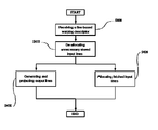
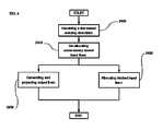
- FIG. 4 is a schematic flow diagram of a method according to an embodiment of the subject application.
- HUD are commonly used to provide visual information to a driver such as vehicle speed, warnings, gas level, gears position, radio setting and position navigation.
- a driver such as vehicle speed, warnings, gas level, gears position, radio setting and position navigation.
- HUD are commonly used to provide visual information to a driver
- persons skilled in the art of safety systems will understand that the proposed solution may also be implemented in other domains having similar objectives such as in the aviation or military fields.
- Image warping can be easily understood if one contemplates, as an example, an image printed on a sheet of rubber. In fact, image warping has the same effect on an image as does stretching or pinching the rubber sheet at interesting places. Such desired distortion of an image may be modelled by a warping transformation function Warp( ). In other words, and relative to the automotive field, a warping transformation function Warp( ) mathematically describes the way an input image is distorted by the windshield of a car while being projected by a HUD.
- a warping transformation function Warp( ) is usually a non-linear function which consists of a set of parameters defining the correspondence between an input pixel in an input image image input given to the HUD and an output pixel of an output image image output observed in the line of sight of the driver.
- Warp( ) is usually a non-linear function which consists of a set of parameters defining the correspondence between an input pixel in an input image image input given to the HUD and an output pixel of an output image image output observed in the line of sight of the driver.
- warping can be performed in two ways:
- FIG. 1 there is diagrammatically shown therein an exemplary head-up display (HUD) system 1000 according to an embodiment of the subject application.
- the communication system 1000 as shown comprises:
- a script-driven HUD controller 100 a script-driven HUD controller 100 .
- a storing unit 300 such as a read only memory (ROM) or random access memory (RAM).
- ROM read only memory
- RAM random access memory
- the storing unit 300 is adapted to store at least one source image 301 and a line-based warping descriptor 302 .
- the storing unit 300 may be implemented as a first memory adapted to store the source image 301 and a second memory adapted to store the line-based warping descriptor 302 , for instance.
- the source image 301 may be a digital image of a given format representing the speed of the vehicle, warnings, gas level, gears position, radio setting and position navigation.
- the line-based warping descriptor 302 may be a binary file, a text file, or a combination thereof.
- the storing unit 300 is operably coupled to the script-driven HUD controller 100 .
- the non-flat display unit 200 is adapted to reflect a projected image into the line of sight of a driver of a car. Therefore, for instance, the non-flat display unit may be the windshield of the car.
- other non-flat display units having different form factor i.e., shape, size, curvature and structure
- form factor i.e., shape, size, curvature and structure
- the script-driven HUD controller 100 as shown comprises:
- an image projection unit 120 such as a projector.
- the image warping unit 110 and the image projection unit 120 may be implemented as hardware, software or any combination thereof, for instance.
- the image projection unit 120 is adapted to project lines of an output image, referred to as output lines, onto the non-flat display unit 200 .
- lines of an output image referred to as output lines
- the image warping unit 110 is adapted to generate at least one output line where the output image corresponds to the result of an electronic image warping of the source image 301 .
- the electronic image warping process may be performed by the image warping unit 110 .
- the image warping unit 110 is operably coupled to the image projection unit 120 and is adapted to receive the line-based warping descriptor 302 .
- the line-based warping descriptor 302 comprises a first information associated with a distortion of a test pattern image caused by the non-flat display unit 200 while the test pattern image is projected by the image projection unit 120 onto the non-flat display unit 200 without prior application of an electronic image warping process to the test pattern image.
- the first information mathematically describes the distortion of a projected image due to the non-flat display unit 200 .
- the first information may be associated with the above-mentioned warping transformation function Warp( ).
- the image warping unit 110 in response to the reception of the line-based warping descriptor 302 , the image warping unit 110 is further adapted to, based on the line-based warping descriptor 302 , fetch one or more lines of the source image 301 , thereinafter referred to as input lines.
- the image warping unit 110 is also further adapted to generate at least one output line of the output image, the at least one output line being associated with an electronic image warping of one or more pixels of the one or more input lines.
- the image warping unit 110 is further adapted to output the at least one output line to the image projection unit 120 for projection onto the non-flat display unit.
- the image warping unit 110 as shown comprises a processing unit 111 and a line-buffer-based memory 112 .
- the line-buffer-based memory 112 may be a dual port circular line-buffer-based memory comprising independent first input port 112 1 and second output port 112 2 , respectively adapted to simultaneously store input lines and output one or more pixels of one or more stored input lines.
- the line-buffer-based memory 112 may comprise at least one memory instance adapted to store input lines or output one or more pixels of one or more stored input lines according to a time-multiplexed scheme. Namely, in this embodiment it is not possible to store input lines and output stored input lines at the same time for a given memory instance of line-buffer-based memory 112 .
- the line-buffer-based memory 112 is adapted to store the one or more input lines of the source image 301 .
- an electronic image warping process usually requires one or more inputs lines since the distortion due to the non-flat display 200 for a given output pixel may originate from several input pixels coming from one or more different input lines. This is due to the fact that an input image is usually distorted vertically and horizontally while being projected on the non-flat display 200 .
- the line-buffer-based memory 112 may be physically limited in terms of the maximum number of fetched input lines to be stored at once versus the image warping unit 110 outputting one output line.
- the line-buffer-based memory 112 may have a limited size of ten lines and be allowed to store two fetched input lines while the image warping unit 110 outputs one output line.
- the image warping unit 110 is configured to:
- the image warping unit 110 fetches two input lines (i.e., lines 1 and 2 ) of the source image and stores them into the line-buffer-based memory 112 .
- the stored input lines are represented as hashed lines.
- T 1 there is no fetching issue since it is allowed to fetch up to two input lines and it has been fetched two input lines.
- no output line is generated since fetching and outputting are to be performed in parallel and the two required input lines for generating the first output line were not present on time.
- it is fetched two additional input lines (i.e., lines 3 and 4 ) and the first output line is generated.
- T 0 may correspond to a moment in time wherein image warping unit 110 is prevented from doing anything visible to the non-flat display until after a new output image is started to be displayed (e.g., vertical sync).
- the image warping unit 110 fetches three input lines (i.e., lines 1 , 2 and 3 ) of the source image and stores them into the line-buffer-based memory 112 .
- no output line is generated by the image warping unit 110 since nothing is to be displayed onto the non-flat display unit 200 during this moment.
- T 1 it is fetched two additional input lines (i.e., lines 4 and 5 ) and the first output line may be generated.
- T 2 one additional input lines is fetched (i.e., lines 6 ) and the second output line may be outputted since at T 1 we already fetched the missing two lines to have the required five input lines in the line-buffer-based memory 112 . Therefore, with such proposed buffer management that can be determine off-line, it is possible to generate the first and second output lines on time.
- the foregoing problem may be solved by knowing in advance the content of the line-buffer-based memory 112 at any moment in time such that pre-fetching may be performed in advance in order to anticipate any shortage of stored input lines necessary to generate output lines.
- performing such buffer management on-the-fly in the hardware is quite tricky and may result in a loss of synchronisation with the non-flat display unit 200 which could be catastrophic.
- critical information such as vehicle speed, or position navigation may not be displayed to the driver anymore thus probably leading to a loss attention of the driver.
- buffer management is rather static and therefore it can be pre-calculated off-line as proposed in the subject application.
- the line-based warping descriptor 302 further comprises a second information associated with buffer management instructions which are calculated off-line based on at least:
- the line-buffer-based memory 112 may be physically limited in terms of the maximum number of fetched input lines to be stored at once versus the image warping unit 110 outputting one output line.
- the storing unit 300 may be shared by other components of the HUD system 1000 or other components of a system comprising the HUD system 1000 such as a graphic processing unit (GPU) or a common processing resources (e.g., a CPU). It is reminded that the source image 301 and the line-based warping descriptor 302 are stored on the storing unit 300 . Therefore, if the storing unit 300 is shared, this means that the processing unit 111 may not necessarily access them when needed.
- GPU graphic processing unit
- a common processing resources e.g., a CPU
- the GPU needs at least 30% of the bandwidth to the storing unit 300 or 100% of the bandwidth during a first period of time and 50% of the bandwidth during a second period of time.
- the storing unit 300 needs to be load-balanced between the processing unit 111 needs and those of the GPU.
- determining in off-line calculations the buffer management instructions would be much easier than doing it on-the-fly since bandwidth requirements for the image warping unit 110 could be average out over time.
- the processing unit 111 is adapted to perform the operations of:
- the second information could be seen by the processing unit 111 as a script giving instructions as to how the line-buffer-based memory 112 should be managed at given moment in time for a given output line to be outputted.
- the line-based warping descriptor 302 may further comprise a third information describing an association of one output pixel of an output line with one or more input pixels of one or more input lines stored in the line-buffer-based memory 112 .
- the line-based warping descriptor 302 may further comprise a fourth information describing an interpolation scheme to be used by the line-buffer-based memory 112 in order to generate the corresponding output pixel. For instance, bilinear interpolation or bicubic interpolation may be indicated in the fourth information.
- the fourth information may be different for every output pixel associated with more than one input pixels. Also, the fourth information may be similar for groups of contiguous output pixels associated with more than one input pixels.
- the line-based warping descriptor may further comprise a fifth information describing how the output pixel is to be displayed on the non-flat display unit 200 ;
- the image warping unit may be further adapted to generate the output pixel based on the fifth information.
- the fifth information may instruct the processing unit 111 to generate an output pixel not based on any input pixel.
- the fifth information may instruct the processing unit 111 to generate an output pixel with a special characteristics for it to appear as being invisible. For instance, such output pixels could be set to a black or white color depending on the environment and the type of non-flat display unit 200 .
- the image warping unit 110 may be further adapted to, when outputting the current output line, fetch one or more lines input lines associated with the generation of at least one further output line yet to be outputted.
- the allocated input lines may be pre-fetched in advance, at certain moment in time in order to prevent any shortage of stored input lines required to generate an output line. For example, if at a given moment in time it is allowed to fetch five input lines but it is need only three input lines for the current output line, it may be more efficient to fetch four or five input lines at once in preparation for a further output line yet to be generated.
- FIG. 4 there is diagrammatically shown therein a flow diagram of a method according to an embodiment of the subject application and with regard to the HUD controller 110 of FIG. 2 .
- S 400 it is received at the image warping unit 110 a line-based warping descriptor 302 and a source image 301 .
- the proposed solution implements a complete image warping unit 110 on-chip without the use of off-chip memories by solely using the line-buffer-based memory 112 of the image warping unit 110 which is configured to receive lines of pixels coming from the input image.
- This solution is achieved by the image warping unit 110 being driven by a script instructing the processing unit 111 to perform proper buffer management.
- the subject application takes advantage of external processing resources capabilities in order to determine buffer management instructions to be followed by the processing unit 111 of the image warping unit 110 thus avoiding the need to perform, on chip, on-the-fly resourceful calculations.
- the proposed solution may require less processing resources on-chip, thus reducing power consumption, saving access bandwidth memory and saving off-chip memories.
- first, second, third, fourth and fifth information may be combined into one or more information inside the line-based warping descriptor 302 .
- first, third and fourth information may be combined into a single information describing the distortion due to the non-flat display unit 200 and the association between output lines and input lines.
- the proposed solution may also be implemented in a computer program product stored in a non-transitory computer-readable storage medium that stores computer-executable code which causes a processor computer to perform the operation of the image warping module 110 , for instance.
- a computer program product is a list of instructions such as a particular application program and/or an operating system.
- the computer program may for example include one or more of: a subroutine, a function, a procedure, an object method, an object implementation, an executable application, an applet, a servlet, a source code, an object code, a shared library/dynamic load library and/or other sequence of instructions designed for execution on a computer system.
- the computer program may be stored internally on computer readable storage medium or transmitted to the computer system via a computer readable transmission medium. All or some of the computer program may be provided on computer readable media permanently, removably or remotely coupled to an information processing system.
- the computer readable media may include, for example and without limitation, any number of the following: magnetic storage media including disk and tape storage media; optical storage media such as compact disk media (e.g., CD-ROM, CD-R, etc.) and digital video disk storage media; non-volatile memory unit storage media including semiconductor-based memory units such as FLASH memory, EEPROM, EPROM, ROM; ferromagnetic digital memories; MRAM; volatile storage media including registers, buffers or caches, main memory, RAM, etc.; and data transmission media including computer networks, point-to-point telecommunication equipment, and carrier wave transmission media, just to name a few.
- a computer process typically includes an executing (running) program or portion of a program, current program values and state information, and the resources used by the operating system to manage the execution of the process.
- An operating system is the software that manages the sharing of the resources of a computer and provides programmers with an interface used to access those resources.
- An operating system processes system data and user input, and responds by allocating and managing tasks and internal system resources as an operation to users and programs of the system.
- the computer system may for example include at least one processing unit, associated memory unit and a number of input/output (I/O) devices.
- I/O input/output
- the computer system processes information according to the computer program and produces resultant output information via I/O devices.
- logic blocks are merely illustrative and that alternative embodiments may merge logic blocks or circuit elements or impose an alternate decomposition of functionality upon various logic blocks or circuit elements.
- the architectures depicted herein are merely exemplary, and that in fact many other architectures may be implemented which achieve the same functionality.
- the user alert device and the driver alert may be combined in a single module.
- one or more sensors may be combined in a single module.
- any arrangement of devices to achieve the same functionality is effectively “associated” such that the desired functionality is achieved.
- any two devices herein combined to achieve a particular functionality may be seen as “associated with” each other such that the desired functionality is achieved, irrespective of architectures or intermediate devices.
- any two devices so associated can also be viewed as being “operably connected,” or “operably coupled,” to each other to achieve the desired functionality.
- the examples, or portions thereof may implemented as soft or code representations of physical circuitry or of logical representations convertible into physical circuitry, such as in a hardware description language of any appropriate type.
- the proposed solution is not limited to physical devices or units implemented in nonprogrammable hardware but can also be applied in programmable devices or units able to perform the desired device functions by operating in accordance with suitable program code, such as mainframes, minicomputers, servers, workstations, personal computers, notepads, personal digital assistants, electronic games, automotive and other embedded systems, cell phones and various other wireless devices, commonly denoted in this application as ‘computer systems’.
- suitable program code such as mainframes, minicomputers, servers, workstations, personal computers, notepads, personal digital assistants, electronic games, automotive and other embedded systems, cell phones and various other wireless devices, commonly denoted in this application as ‘computer systems’.
- any reference signs placed between parentheses shall not be construed as limiting the claim.
- the word ‘comprising’ does not exclude the presence of other elements or operations then those listed in a claim.
- the terms “a” or “an,” as used herein, are defined as one or as more than one.
Landscapes
- Physics & Mathematics (AREA)
- General Physics & Mathematics (AREA)
- Optics & Photonics (AREA)
- Engineering & Computer Science (AREA)
- Theoretical Computer Science (AREA)
- Controls And Circuits For Display Device (AREA)
- Control Of Indicators Other Than Cathode Ray Tubes (AREA)
Abstract
-
- receive a line-based warping descriptor comprising first information associated with a distortion caused by a non-flat display; and,
- in response to the reception of the line-based warping descriptor, the image warping unit is further adapted to, based on the line-based warping descriptor:
- fetch one or more lines of the source image; and,
- output to the image projection unit at least one output line of the output image associated with an electronic image warping of one or more pixels of the one or more input lines,
and wherein the line-based warping descriptor further comprises second information associated with buffer management instructions calculated off-line.
Description
-
- forwardly, by looping over all pixels in the input image imageinput and projecting them into the output image imageoutput based on the warping transformation function Warp( ), or
- backwardly, by sampling for each output pixel the corresponding pixels in the input images imageoutput.
-
- the first information mathematically describing the distortion due to the
non-flat display unit 200; and, - one physical characteristic of the line-buffer-based
memory 112.
- the first information mathematically describing the distortion due to the
-
- allocating fetched input lines into the line-buffer-based
memory 112, and - de-allocating input lines from the line-buffer-based
memory 112 when not needed by theimage warping unit 110.
- allocating fetched input lines into the line-buffer-based
Claims (17)
Applications Claiming Priority (1)
| Application Number | Priority Date | Filing Date | Title |
|---|---|---|---|
| PCT/IB2013/058929 WO2015044716A1 (en) | 2013-09-27 | 2013-09-27 | Head-up display warping controller |
Publications (2)
| Publication Number | Publication Date |
|---|---|
| US20160247255A1 US20160247255A1 (en) | 2016-08-25 |
| US10026151B2 true US10026151B2 (en) | 2018-07-17 |
Family
ID=52742153
Family Applications (1)
| Application Number | Title | Priority Date | Filing Date |
|---|---|---|---|
| US15/024,774 Active US10026151B2 (en) | 2013-09-27 | 2013-09-27 | Head-up display warping controller |
Country Status (2)
| Country | Link |
|---|---|
| US (1) | US10026151B2 (en) |
| WO (1) | WO2015044716A1 (en) |
Families Citing this family (5)
| Publication number | Priority date | Publication date | Assignee | Title |
|---|---|---|---|---|
| US20170178288A1 (en) * | 2015-12-21 | 2017-06-22 | Stanislaw Adaszewski | Two-dimensional piecewise approximation to compress image warping fields |
| KR101785027B1 (en) * | 2016-01-14 | 2017-11-06 | 주식회사 라온텍 | Image distortion compensation display device and image distortion compensation method using the same |
| DE102016212687A1 (en) | 2016-07-12 | 2018-01-18 | Audi Ag | Method for operating a display device of a motor vehicle |
| DE102016224166B3 (en) | 2016-12-05 | 2018-05-30 | Continental Automotive Gmbh | Head-Up Display |
| US10043318B2 (en) * | 2016-12-09 | 2018-08-07 | Qualcomm Incorporated | Display synchronized image warping |
Citations (21)
| Publication number | Priority date | Publication date | Assignee | Title |
|---|---|---|---|---|
| US6272431B1 (en) * | 1997-04-29 | 2001-08-07 | Thomas Zamojdo | Method for displaying a map in a vehicle en-route guidance system |
| US20030058368A1 (en) * | 2001-09-24 | 2003-03-27 | Mark Champion | Image warping using pixel pages |
| US20030215230A1 (en) * | 2002-05-14 | 2003-11-20 | Eastman Kodak Company | Method and system for correcting non-symmetric distortion in an image |
| JP2004098834A (en) * | 2002-09-09 | 2004-04-02 | Denso Corp | Vehicular head-up display |
| JP2004226469A (en) * | 2003-01-20 | 2004-08-12 | Denso Corp | Head-up display device for vehicle |
| JP2006091104A (en) | 2004-09-21 | 2006-04-06 | Denso Corp | Head up display for vehicle |
| US20060267925A1 (en) * | 2005-05-30 | 2006-11-30 | Renesas Technology Corp. | Liquid crystal display drive and control device, morbile terminal system, and data processing system |
| US20070159317A1 (en) * | 2006-01-10 | 2007-07-12 | Denso Corporation | Display apparatus |
| US20070291051A1 (en) * | 2003-05-19 | 2007-12-20 | Microvision, Inc. | Image generation with interpolation and distortion correction |
| JP2008010518A (en) | 2006-06-27 | 2008-01-17 | Citizen Holdings Co Ltd | Fluorescent device |
| US20080088527A1 (en) * | 2006-10-17 | 2008-04-17 | Keitaro Fujimori | Heads Up Display System |
| US20080088528A1 (en) * | 2006-10-17 | 2008-04-17 | Takashi Shindo | Warp Image Circuit |
| US20080088526A1 (en) * | 2006-10-17 | 2008-04-17 | Tatiana Pavlovna Kadantseva | Method And Apparatus For Rendering An Image Impinging Upon A Non-Planar Surface |
| US20080101711A1 (en) * | 2006-10-26 | 2008-05-01 | Antonius Kalker | Rendering engine for forming an unwarped reproduction of stored content from warped content |
| US20080297868A1 (en) * | 2007-05-28 | 2008-12-04 | Konica Minolta Opto, Inc. | Image display apparatus |
| US20100253489A1 (en) * | 2009-04-02 | 2010-10-07 | Gm Global Technology Operations, Inc. | Distortion and perspective correction of vector projection display |
| US20110227937A1 (en) * | 2010-03-17 | 2011-09-22 | Qualcomm Mems Technologies, Inc. | System and method for frame buffer storage and retrieval in alternating orientations |
| US20120224062A1 (en) * | 2009-08-07 | 2012-09-06 | Light Blue Optics Ltd | Head up displays |
| US20130083298A1 (en) * | 2011-09-30 | 2013-04-04 | Seiko Epson Corporation | Projector and method for controlling projector |
| US20140002503A1 (en) * | 2012-07-02 | 2014-01-02 | Seiko Epson Corporation | Projector and method for controlling the same |
| US8766998B1 (en) * | 2008-08-22 | 2014-07-01 | Aechelon Technology, Inc. | Sampling of non-planar display surfaces |
-
2013
- 2013-09-27 US US15/024,774 patent/US10026151B2/en active Active
- 2013-09-27 WO PCT/IB2013/058929 patent/WO2015044716A1/en active Application Filing
Patent Citations (21)
| Publication number | Priority date | Publication date | Assignee | Title |
|---|---|---|---|---|
| US6272431B1 (en) * | 1997-04-29 | 2001-08-07 | Thomas Zamojdo | Method for displaying a map in a vehicle en-route guidance system |
| US20030058368A1 (en) * | 2001-09-24 | 2003-03-27 | Mark Champion | Image warping using pixel pages |
| US20030215230A1 (en) * | 2002-05-14 | 2003-11-20 | Eastman Kodak Company | Method and system for correcting non-symmetric distortion in an image |
| JP2004098834A (en) * | 2002-09-09 | 2004-04-02 | Denso Corp | Vehicular head-up display |
| JP2004226469A (en) * | 2003-01-20 | 2004-08-12 | Denso Corp | Head-up display device for vehicle |
| US20070291051A1 (en) * | 2003-05-19 | 2007-12-20 | Microvision, Inc. | Image generation with interpolation and distortion correction |
| JP2006091104A (en) | 2004-09-21 | 2006-04-06 | Denso Corp | Head up display for vehicle |
| US20060267925A1 (en) * | 2005-05-30 | 2006-11-30 | Renesas Technology Corp. | Liquid crystal display drive and control device, morbile terminal system, and data processing system |
| US20070159317A1 (en) * | 2006-01-10 | 2007-07-12 | Denso Corporation | Display apparatus |
| JP2008010518A (en) | 2006-06-27 | 2008-01-17 | Citizen Holdings Co Ltd | Fluorescent device |
| US20080088527A1 (en) * | 2006-10-17 | 2008-04-17 | Keitaro Fujimori | Heads Up Display System |
| US20080088528A1 (en) * | 2006-10-17 | 2008-04-17 | Takashi Shindo | Warp Image Circuit |
| US20080088526A1 (en) * | 2006-10-17 | 2008-04-17 | Tatiana Pavlovna Kadantseva | Method And Apparatus For Rendering An Image Impinging Upon A Non-Planar Surface |
| US20080101711A1 (en) * | 2006-10-26 | 2008-05-01 | Antonius Kalker | Rendering engine for forming an unwarped reproduction of stored content from warped content |
| US20080297868A1 (en) * | 2007-05-28 | 2008-12-04 | Konica Minolta Opto, Inc. | Image display apparatus |
| US8766998B1 (en) * | 2008-08-22 | 2014-07-01 | Aechelon Technology, Inc. | Sampling of non-planar display surfaces |
| US20100253489A1 (en) * | 2009-04-02 | 2010-10-07 | Gm Global Technology Operations, Inc. | Distortion and perspective correction of vector projection display |
| US20120224062A1 (en) * | 2009-08-07 | 2012-09-06 | Light Blue Optics Ltd | Head up displays |
| US20110227937A1 (en) * | 2010-03-17 | 2011-09-22 | Qualcomm Mems Technologies, Inc. | System and method for frame buffer storage and retrieval in alternating orientations |
| US20130083298A1 (en) * | 2011-09-30 | 2013-04-04 | Seiko Epson Corporation | Projector and method for controlling projector |
| US20140002503A1 (en) * | 2012-07-02 | 2014-01-02 | Seiko Epson Corporation | Projector and method for controlling the same |
Non-Patent Citations (4)
| Title |
|---|
| Internation Search Report for the International application No. PCT/IB2013/058929 dated Jun. 16, 2014. |
| Motten et al., "Adaptive memory architecture for real-time image warping", IEEE 2012, pp. 466-471. |
| Wolberg, George, "Digital Image Warping", IEEE Computer Society Press, 1988 (extract-electronic file not available). |
| Wolberg, George, "Digital Image Warping", IEEE Computer Society Press, 1988 (extract—electronic file not available). |
Also Published As
| Publication number | Publication date |
|---|---|
| US20160247255A1 (en) | 2016-08-25 |
| WO2015044716A1 (en) | 2015-04-02 |
Similar Documents
| Publication | Publication Date | Title |
|---|---|---|
| KR101980990B1 (en) | Exploiting frame to frame coherency in a sort-middle architecture | |
| US10885607B2 (en) | Storage for foveated rendering | |
| US10026151B2 (en) | Head-up display warping controller | |
| CN113225427B (en) | Image display method and terminal equipment | |
| US8384738B2 (en) | Compositing windowing system | |
| US9569862B2 (en) | Bandwidth reduction using texture lookup by adaptive shading | |
| US10410398B2 (en) | Systems and methods for reducing memory bandwidth using low quality tiles | |
| US9934739B2 (en) | Low power symbology generator and display driver | |
| US20200273431A1 (en) | Display control device and method, and display system | |
| US9766458B2 (en) | Image generating system, image generating method, and information storage medium | |
| US20190035049A1 (en) | Dithered variable rate shading | |
| US20150194131A1 (en) | Image data output control method and electronic device supporting the same | |
| US20130107055A1 (en) | Image synthesis device | |
| CN107646131B (en) | Dithering for image data to be displayed | |
| JP6480100B2 (en) | Semiconductor device, video display system, and signal processing method | |
| CN109697739B (en) | Reverse color display method of handwriting reading equipment and handwriting reading equipment | |
| US10672367B2 (en) | Providing data to a display in data processing systems | |
| US10417814B2 (en) | Method and apparatus for blending layers within a graphics display component | |
| CN109859328B (en) | Scene switching method, device, equipment and medium | |
| CN114765018A (en) | Transparent display device and method of driving the same | |
| JP2008092316A (en) | Display device | |
| JP2019082727A (en) | Semiconductor device, video display system, and signal processing method | |
| CN113936615A (en) | Image display method, image display system, display device, head-mounted display device, and medium |
Legal Events
| Date | Code | Title | Description |
|---|---|---|---|
| AS | Assignment |
Owner name: FREESCALE SEMICONDUCTOR, INC., TEXAS Free format text: ASSIGNMENT OF ASSIGNORS INTEREST;ASSIGNORS:STAUDENMAIER, MICHAEL ANDREAS;BAJAJ, KSHITIJ;SINGH, CHANPREET;SIGNING DATES FROM 20130927 TO 20131015;REEL/FRAME:038096/0526 |
|
| AS | Assignment |
Owner name: MORGAN STANLEY SENIOR FUNDING, INC., MARYLAND Free format text: SUPPLEMENT TO THE SECURITY AGREEMENT;ASSIGNOR:FREESCALE SEMICONDUCTOR, INC.;REEL/FRAME:039138/0001 Effective date: 20160525 |
|
| AS | Assignment |
Owner name: NXP, B.V., F/K/A FREESCALE SEMICONDUCTOR, INC., NETHERLANDS Free format text: RELEASE BY SECURED PARTY;ASSIGNOR:MORGAN STANLEY SENIOR FUNDING, INC.;REEL/FRAME:040925/0001 Effective date: 20160912 Owner name: NXP, B.V., F/K/A FREESCALE SEMICONDUCTOR, INC., NE Free format text: RELEASE BY SECURED PARTY;ASSIGNOR:MORGAN STANLEY SENIOR FUNDING, INC.;REEL/FRAME:040925/0001 Effective date: 20160912 |
|
| AS | Assignment |
Owner name: MORGAN STANLEY SENIOR FUNDING, INC., MARYLAND Free format text: CORRECTIVE ASSIGNMENT TO CORRECT THE INCORRECT PCT NUMBERS IB2013000664, US2013051970, US201305935 PREVIOUSLY RECORDED AT REEL: 037444 FRAME: 0787. ASSIGNOR(S) HEREBY CONFIRMS THE ASSIGNMENT AND ASSUMPTION OF SECURITY INTEREST IN PATENTS;ASSIGNOR:CITIBANK, N.A.;REEL/FRAME:040450/0715 Effective date: 20151207 |
|
| AS | Assignment |
Owner name: NXP B.V., NETHERLANDS Free format text: RELEASE BY SECURED PARTY;ASSIGNOR:MORGAN STANLEY SENIOR FUNDING, INC.;REEL/FRAME:040928/0001 Effective date: 20160622 |
|
| AS | Assignment |
Owner name: NXP USA, INC., TEXAS Free format text: CHANGE OF NAME;ASSIGNOR:FREESCALE SEMICONDUCTOR INC.;REEL/FRAME:040626/0683 Effective date: 20161107 |
|
| AS | Assignment |
Owner name: NXP USA, INC., TEXAS Free format text: CORRECTIVE ASSIGNMENT TO CORRECT THE NATURE OF CONVEYANCE PREVIOUSLY RECORDED AT REEL: 040626 FRAME: 0683. ASSIGNOR(S) HEREBY CONFIRMS THE MERGER AND CHANGE OF NAME;ASSIGNOR:FREESCALE SEMICONDUCTOR INC.;REEL/FRAME:041414/0883 Effective date: 20161107 Owner name: NXP USA, INC., TEXAS Free format text: CORRECTIVE ASSIGNMENT TO CORRECT THE NATURE OF CONVEYANCE PREVIOUSLY RECORDED AT REEL: 040626 FRAME: 0683. ASSIGNOR(S) HEREBY CONFIRMS THE MERGER AND CHANGE OF NAME EFFECTIVE NOVEMBER 7, 2016;ASSIGNORS:NXP SEMICONDUCTORS USA, INC. (MERGED INTO);FREESCALE SEMICONDUCTOR, INC. (UNDER);SIGNING DATES FROM 20161104 TO 20161107;REEL/FRAME:041414/0883 |
|
| STCF | Information on status: patent grant |
Free format text: PATENTED CASE |
|
| AS | Assignment |
Owner name: NXP B.V., NETHERLANDS Free format text: RELEASE BY SECURED PARTY;ASSIGNOR:MORGAN STANLEY SENIOR FUNDING, INC.;REEL/FRAME:050744/0097 Effective date: 20190903 |
|
| AS | Assignment |
Owner name: NXP B.V., NETHERLANDS Free format text: CORRECTIVE ASSIGNMENT TO CORRECT THE REMOVEAPPLICATION 11759915 AND REPLACE IT WITH APPLICATION11759935 PREVIOUSLY RECORDED ON REEL 040928 FRAME 0001. ASSIGNOR(S) HEREBY CONFIRMS THE RELEASE OF SECURITYINTEREST;ASSIGNOR:MORGAN STANLEY SENIOR FUNDING, INC.;REEL/FRAME:052915/0001 Effective date: 20160622 |
|
| AS | Assignment |
Owner name: NXP, B.V. F/K/A FREESCALE SEMICONDUCTOR, INC., NETHERLANDS Free format text: CORRECTIVE ASSIGNMENT TO CORRECT THE REMOVEAPPLICATION 11759915 AND REPLACE IT WITH APPLICATION11759935 PREVIOUSLY RECORDED ON REEL 040925 FRAME 0001. ASSIGNOR(S) HEREBY CONFIRMS THE RELEASE OF SECURITYINTEREST;ASSIGNOR:MORGAN STANLEY SENIOR FUNDING, INC.;REEL/FRAME:052917/0001 Effective date: 20160912 |
|
| MAFP | Maintenance fee payment |
Free format text: PAYMENT OF MAINTENANCE FEE, 4TH YEAR, LARGE ENTITY (ORIGINAL EVENT CODE: M1551); ENTITY STATUS OF PATENT OWNER: LARGE ENTITY Year of fee payment: 4 |