US10025115B2 - Spectacle lens having a plurality of diffraction structures for light - Google Patents
Spectacle lens having a plurality of diffraction structures for light Download PDFInfo
- Publication number
- US10025115B2 US10025115B2 US15/359,476 US201615359476A US10025115B2 US 10025115 B2 US10025115 B2 US 10025115B2 US 201615359476 A US201615359476 A US 201615359476A US 10025115 B2 US10025115 B2 US 10025115B2
- Authority
- US
- United States
- Prior art keywords
- diffraction
- light
- angle
- wavelength
- incidence
- Prior art date
- Legal status (The legal status is an assumption and is not a legal conclusion. Google has not performed a legal analysis and makes no representation as to the accuracy of the status listed.)
- Active, expires
Links
Images


Classifications
-
- G—PHYSICS
- G02—OPTICS
- G02C—SPECTACLES; SUNGLASSES OR GOGGLES INSOFAR AS THEY HAVE THE SAME FEATURES AS SPECTACLES; CONTACT LENSES
- G02C7/00—Optical parts
- G02C7/02—Lenses; Lens systems ; Methods of designing lenses
- G02C7/06—Lenses; Lens systems ; Methods of designing lenses bifocal; multifocal ; progressive
- G02C7/061—Spectacle lenses with progressively varying focal power
- G02C7/063—Shape of the progressive surface
-
- B—PERFORMING OPERATIONS; TRANSPORTING
- B29—WORKING OF PLASTICS; WORKING OF SUBSTANCES IN A PLASTIC STATE IN GENERAL
- B29D—PRODUCING PARTICULAR ARTICLES FROM PLASTICS OR FROM SUBSTANCES IN A PLASTIC STATE
- B29D11/00—Producing optical elements, e.g. lenses or prisms
- B29D11/00009—Production of simple or compound lenses
-
- B—PERFORMING OPERATIONS; TRANSPORTING
- B29—WORKING OF PLASTICS; WORKING OF SUBSTANCES IN A PLASTIC STATE IN GENERAL
- B29D—PRODUCING PARTICULAR ARTICLES FROM PLASTICS OR FROM SUBSTANCES IN A PLASTIC STATE
- B29D11/00—Producing optical elements, e.g. lenses or prisms
- B29D11/0074—Production of other optical elements not provided for in B29D11/00009- B29D11/0073
- B29D11/00769—Producing diffraction gratings
-
- G—PHYSICS
- G02—OPTICS
- G02B—OPTICAL ELEMENTS, SYSTEMS OR APPARATUS
- G02B27/00—Optical systems or apparatus not provided for by any of the groups G02B1/00 - G02B26/00, G02B30/00
- G02B27/42—Diffraction optics, i.e. systems including a diffractive element being designed for providing a diffractive effect
- G02B27/4266—Diffraction theory; Mathematical models
-
- G—PHYSICS
- G02—OPTICS
- G02B—OPTICAL ELEMENTS, SYSTEMS OR APPARATUS
- G02B5/00—Optical elements other than lenses
- G02B5/32—Holograms used as optical elements
-
- G—PHYSICS
- G02—OPTICS
- G02C—SPECTACLES; SUNGLASSES OR GOGGLES INSOFAR AS THEY HAVE THE SAME FEATURES AS SPECTACLES; CONTACT LENSES
- G02C7/00—Optical parts
- G02C7/02—Lenses; Lens systems ; Methods of designing lenses
- G02C7/024—Methods of designing ophthalmic lenses
- G02C7/028—Special mathematical design techniques
-
- G—PHYSICS
- G02—OPTICS
- G02C—SPECTACLES; SUNGLASSES OR GOGGLES INSOFAR AS THEY HAVE THE SAME FEATURES AS SPECTACLES; CONTACT LENSES
- G02C7/00—Optical parts
- G02C7/02—Lenses; Lens systems ; Methods of designing lenses
- G02C7/06—Lenses; Lens systems ; Methods of designing lenses bifocal; multifocal ; progressive
-
- G—PHYSICS
- G02—OPTICS
- G02C—SPECTACLES; SUNGLASSES OR GOGGLES INSOFAR AS THEY HAVE THE SAME FEATURES AS SPECTACLES; CONTACT LENSES
- G02C2202/00—Generic optical aspects applicable to one or more of the subgroups of G02C7/00
- G02C2202/20—Diffractive and Fresnel lenses or lens portions
-
- G—PHYSICS
- G02—OPTICS
- G02C—SPECTACLES; SUNGLASSES OR GOGGLES INSOFAR AS THEY HAVE THE SAME FEATURES AS SPECTACLES; CONTACT LENSES
- G02C2202/00—Generic optical aspects applicable to one or more of the subgroups of G02C7/00
- G02C2202/22—Correction of higher order and chromatic aberrations, wave front measurement and calculation
Definitions
- the invention relates to a spectacle lens for an observer, comprising a body which is transparent or at least partly transparent to light and has a phase object which guides the light incident at an angle of incidence ⁇ on a side distant from the observer into a direction depending on the wavelength ⁇ of the light and the angle of incidence ⁇ of the light.
- the invention also extends to a production method for such a spectacle lens, and to a method for establishing the configuration of such a spectacle lens.
- a spectacle lens of the type set forth at the outset is known from WO 99/34248 A1.
- a spectacle lens with holographic optical elements (HOE) lying one above the other is described therein.
- the holographic optical elements form a volume grating, by means of which the light incident on the spectacle lens at a certain angle of incidence is diffracted, leading to deflection of the light, incident on the spectacle lens, for this angle of incidence.
- WO 2014/064163 A1 describes a spectacle lens with a multiplicity of light-diffracting zones, which have a different refractive power.
- Spectacle lenses in the form of refractive progressive lenses allow an observer suffering from a visual impairment to be able to observe objects arranged at different distances with a more or less sharp visual impression, even if the accommodation capability of the eyes of this observer is no longer there, for example, due to old age, or greatly limited.
- Visual zones are usually defined for the configuration of refractive progressive lenses. These visual zones relate to regions of the surface of a progressive lens penetrated by the viewing direction of an observer. If the observer peers through different visual zones, this observer can see objects at different object distances in focus, without an eye requiring accommodation herefor.
- Refractive progressive lenses generally have a distance zone which, when these lenses are used as intended, is penetrated by the viewing direction of an eye of an observer peering into the distance. When peering through the distance zone, the objects arranged at infinity for the observer should be imaged in focus on the retina.
- refractive progressive lenses usually also have a so-called near zone in addition to the distance zone, the near zone being spaced apart from the distance zone and, when the progressive lens is used as intended, being peered through by an observer with a maximum accommodation in order to observe objects arranged at a near distance (for example, 40 cm) in front of the eyes.
- Progressive lenses often have a so-called progression channel between the near zone and the distance zone. This progression channel connects the distance zone to the near zone.
- the refractive power of the progressive lens differs locally in the progression channel.
- the progression channel In order to provide a wide visual field to an observer with the progressive lens, attempts are made, as a matter of principle, for the progression channel to be as wide as possible.
- the obtainable width of the progression channel is restricted due to the differential geometric Minkwitz theorem.
- a consequence of this mathematical theorem is that an observer must accept non-correctable astigmatic imaging aberrations with increasing width of the progression channel, that is, an astigmatism caused by the Minkwitz theorem.
- fundamental limits are placed on the imaging quality of refractive progressive lenses and on the possible extent of the near region zone and distance region zone of refractive progressive lenses.
- the optical effect of a spectacle lens is understood to mean the property of deflecting light.
- the invention is based on the idea that, for an observer with a spectacle lens, different distance regions can be visualized in focus and without the astigmatic imaging aberrations necessarily occurring in the peripheral regions of a progressive lens if the light beams imaging the object region are deflected not by refraction but by diffraction.
- the diffraction of light is understood to mean the physical phenomenon of the change in the phase of the light, caused by a phase object, on account of interactions between light and matter.
- a phase object is preferably a transparent object which influences or changes the phase of the light.
- a phase object needs a diffraction structure in order to diffract light at the phase object.
- Such a diffraction structure represents a regular, or else irregular, spatial modulation of the complex refractive index, for example, in the form of a grating, which may extend in one dimension or in two dimensions (plane grating) or in three dimensions (volume grating).
- a diffraction structure diffracts the light in a manner dependent on the angle of incidence of the light, at which it is incident on the diffraction structure, and in a manner dependent on the wavelength ⁇ of the light. If light is diffracted at a diffraction structure, it can be deflected in one or more different, discrete directions due to constructive interference. In the present case, these directions are referred to as orders of diffraction and denoted, in line with general convention, by integers 0, ⁇ 1, ⁇ 2, ⁇ 3, . . . , with the central order being denoted by 0 and all further orders being numbered consecutively.
- ⁇ 1 is understood to mean the deflection of the light in the direction defined by the order of diffraction which arises by constructive interference of phase-shifted light.
- a spectacle lens according to the invention allows an observer, in particular, to perceive objects arranged in different distance regions in focus and without imaging aberrations which distort the visual impression, even in the case of a restricted accommodation capability of the eyes.
- a spectacle lens according to the invention has a body which is transparent or at least partly transparent to the light.
- a body is at least partly transparent to the light.
- the angle to which a light beam is diffracted by a diffraction structure and the angle at which a light beam diffracted by the diffraction structure may be incident on the diffraction structure increase with increasing absolute value of the order of diffraction in this case.
- a positive order of diffraction corresponds to a deflection angle for the light, related to the direction of incidence, which is positive;
- a negative order of diffraction corresponds to a negative deflection angle related to the direction of incidence of the light.
- ⁇ 1 to the intensity I incident of the light incident on a boundary of the diffraction structure at a specific angle of incidence ⁇ ′ is presently referred to as the diffraction efficiency ⁇ of the diffraction structure.
- the boundary of a diffraction structure may coincide with the surface of the transparent body of the spectacle lens, but this need not be the case.
- the boundary of a diffraction structure may also be situated within the transparent body.
- the invention exploits the fact that the diffraction efficiency of a diffraction structure in a layer made of an optically transparent material arranged on a carrier is dependent on:
- the phase object has a multiplicity of diffraction structures, which diffract monochromatic light at a wavelength of 380 nm ⁇ 800 nm with a diffraction efficiency of ⁇ 70% into one and same order of diffraction
- the angle of incidence of the light on a boundary is understood to mean the angle ⁇ formed by the propagation direction of the light with the surface normal ⁇ right arrow over (n) ⁇ of the boundary facing the incident light.
- the phase object of the transparent body of the optical visual aid comprises a multiplicity of diffraction structures, which each deflect all light of a wavelength ⁇ lying in a diffraction-structure-specific wavelength interval ⁇ 0 ⁇ 0.1 ⁇ m, the wavelength being incident at an angle of incidence ⁇ which lies in a diffraction-structure-specific angle of incidence range ⁇ 0 ⁇ 2.5°, preferably at an angle of incidence ⁇ which lies in a diffraction-structure-specific angle of incidence range ⁇ 0 ⁇ 2°, on the side of the spectacle lens distant from the observer, with the diffraction efficiency of ⁇ 70% into one and same order of diffraction
- a single diffraction structure in an optical visual aid according to the invention may have a thickness of 17 ⁇ m and an extent of approximately 25 square millimeters (mm 2 ).
- the optically transparent material may be a photopolymer, in particular a photopolymer which has the formulation described in WO 2012/062658 A1, to which reference is herewith made in the entirety thereof and the disclosure of which is included in the description of the present invention.
- the diffraction structures are preferably embodied in such a way that, in the parameter plane spanned by the angle of incidence ⁇ and the wavelength ⁇ with a wavelength parameter axis and an angle of incidence parameter axis, they approximately each have an efficiency window extending along a straight line, which increases monotonically in relation to the wavelength ⁇ , in which efficiency window the light incident at a specific angle of incidence ⁇ on the side of the spectacle lens distant from the observer is diffracted with the diffraction efficiency of ⁇ 70% into one and same order of diffraction
- a straight line along which the efficiency window extends may, in particular, be a straight line which approximately follows a line passing through the efficiency window and on which the diffraction efficiency is at a maximum.
- the gradient of the diffraction efficiency ⁇ according to the angle of incidence ⁇ and the wavelength ⁇ in the parameter plane spanned by the wavelength ⁇ and the angle of incidence ⁇ extends tangentially at this line.
- ⁇ 0.036°/nm preferably ⁇ 0.024°/nm, particularly preferably ⁇ 0.012°/nm, applies to the gradient ⁇ of the straight line.
- the diffraction structures in the parameter plane spanned by the angle of incidence ⁇ and the wavelength ⁇ with a wavelength parameter axis and an angle of incidence parameter axis can also be embodied in such a way that they each have an efficiency window extending along a straight line, which increases monotonically in relation to the wavelength ⁇ , between a first tangent parallel to the increasing straight line and a second tangent displaced in parallel to the first tangent in the direction of the angle of incidence parameter axis by the angle ⁇ 20°, preferably ⁇ 15°, particularly preferably ⁇ 10° or ⁇ 6°, in which efficiency window the light incident at a specific angle of incidence ⁇ on the spectacle lens is diffracted with the diffraction efficiency of ⁇ 70% into one and same order of diffraction
- the efficiency window may extend approximately symmetrically along the straight line.
- an amplitude ⁇ n( ⁇ ) of the modulation of the complex refractive index n( ⁇ ; x,y,z) may, for example, satisfy the following relationship for the light of the wavelength 380 nm ⁇ 800 nm: 0.01 ⁇
- each diffraction structure forms an actuator-compensator pair with a further diffraction structure which is spatially separate from the diffraction structure, wherein the deflections of the light incident at the angle of incidence on the side of the spectacle lens distant from the observer caused by the diffraction structures forming an actuator-compensator pair are at least partly canceled.
- the diffraction structures forming an actuator-compensator pair may adjoin one another.
- the phase objects forming an actuator-compensator pair may be spaced apart from one another.
- the phase object in the body of the spectacle lens may have an optical effect, that is, a light-deflecting effect, in particular a lens effect.
- the body may also comprise a phase object which is constructed from layers, lying one above the other, of an optically transparent material with a modulated refractive index.
- the layers, lying one above the other, of the optically transparent material may be applied to a carrier transparent to the visible light.
- the spectacle lens may also have a light-refracting effect in addition to the light-diffracting effect.
- the optical effect of the spectacle lens is preferably dependent on a viewing direction, passing through the spectacle lens, of the observer.
- the body of the spectacle lens which is transparent or at least partly transparent to the light, may have an edge and two or more connected visual zones which have a different optical effect, extend over the spectacle lens and cover the spectacle lens in the process, wherein the transparent body of the spectacle lens, in this case, has no regions with an astigmatism caused by the Minkwitz theorem.
- the invention also extends to a method for establishing the configuration of a spectacle lens, in which
- the invention also extends to a method for establishing the configuration of a spectacle lens, in which a predetermined optical transfer function at least partly compensates at least one visual impairment of the observer.
- the invention extends to a production method for a spectacle lens
- FIG. 1 shows spectacles with a spectacle lens according to the invention
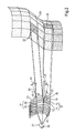
- FIG. 2 shows a three-dimensional partial section of a spectacle lens of the spectacles, with an object surface and with an eye of an observer;
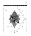
- FIG. 3 shows a spatial visualization of a three-dimensional diffraction structure of the spectacle lens
- FIG. 4 shows a first visualization of the diffraction structure in a sectional plane identified in FIG. 3 ;
- FIG. 5 shows a second visualization of a diffraction structure in the sectional plane identified in FIG. 3 ;
- FIG. 6 shows a magnified portion of the partial section shown in FIG. 2 ;
- FIG. 7 shows a resultant diffraction efficiency of a plurality of diffraction structures which adjoin one another
- FIG. 8 shows a sectional view with the profile of the refractive index in these diffraction structures
- FIG. 9 shows the diffraction efficiency of a first single diffraction structure
- FIG. 10 shows a sectional view with the schematic profile of the refractive index in this first single diffraction structure
- FIG. 11 shows the diffraction efficiency of a second single diffraction structure
- FIG. 12 shows a sectional view with the profile of the refractive index in this second single diffraction structure
- FIG. 13 shows the diffraction efficiency of a third single diffraction structure
- FIG. 14 shows a sectional view with the profile of the refractive index in this third single diffraction structure
- FIG. 15 shows the sum of the diffraction efficiencies of the first, second and third individual diffraction structure
- FIG. 16 shows the production of a spectacle lens with diffraction structures
- FIG. 17 shows an apparatus for producing diffraction structures on a transparent carrier
- FIG. 18 shows the establishment of the configuration of a spectacle lens with diffraction structures
- FIGS. 19 to 23 show various spectacle lenses embodied as progressive lenses or multi-focus lenses.
- the spectacles 10 shown in FIG. 1 comprise a spectacle frame 12 , in which a left spectacle lens 16 and a right spectacle lens 18 are received.
- the spectacles may also be embodied as a monocle with only one spectacle lens.
- the spectacle lenses 16 , 18 each have a body that is transparent to the visible light.
- the configuration of the spectacle lens 16 corresponds to the configuration of the spectacle lens 18 .
- the spectacle lenses 16 , 18 have a preferably individualized optical effect, which has been adapted for the left eye and the right eye of an observer.
- the spectacle lenses 16 , 18 have a body which is produced from plastic which transmits the visible light.
- phase objects 20 , 22 in the transparent body of the spectacle lens 16 and of the spectacle lens 18 .
- These phase objects 20 , 22 contain a multiplicity of diffraction structures.
- FIG. 2 is a three-dimensional partial section of the spectacle lens 16 from FIG. 1 .
- the body of the spectacle lens 16 comprises a carrier 19 made out of an optical plastic.
- the carrier 19 may also consist of, for example, a mineral glass.
- the phase object 20 in the body of the spectacle lens 16 has an optical effect. To this end, it has a multiplicity of diffraction structures 24 , 26 .
- the light from an object surface 29 which reaches through the spectacle lens front surface 23 and is incident on the spectacle lens front surface 23 in the direction of incidence 30 at the angle of incidence ⁇ related to the surface normal ⁇ right arrow over (n) ⁇ , passes through the diffraction structures 24 , 26 in the spectacle lens 16 .
- This light leaves the body of the spectacle lens 16 through the spectacle lens back surface 25 . From there, it is incident on the eye 27 of an observer.
- the diffraction structures 24 , 26 are embodied as a spatial modulation of the complex refractive index of the transparent body of the spectacle lens 16 .
- the second diffraction structure 26 is arranged at a distance from the first diffraction structure 24 . That is, the first diffraction structure 24 and the second diffraction structure 26 are spatially separated from one another here. Hence, there is no overlap between the diffraction structures 24 , 26 in the spectacle lens 16 in the present case.
- actuator-compensator pair 31 the deflection of the light which is caused by one diffraction structure, for example, the diffraction structure 26 , when the light passes through this diffraction structure is at least partially undone by the other diffraction structure, for example, the diffraction structure 24 , if the light also passes through this diffraction structure.
- the phase object of the body of the above-described spectacle lens has a multiplicity of actuator-compensator pairs 31 .
- the diffraction structures forming an actuator-compensator pair 31 need not necessarily adjoin one another but may also be spaced apart from one another.
- the phase object of the spectacle lens 16 contains at least one actuator-compensator pair 31 made of two different diffraction structures 24 , 26 for each surface segment 32 of the object surface 29 , by means of which diffraction structures the light which originates from a surface segment 32 and is incident on the spectacle lens 16 is diffracted in such a way that a sharp image of the relevant surface segment 32 of the object surface 29 arises on the retina 36 of the eye 27 of the observer.
- the actuator-compensator pairs 31 in the phase object of the spectacle lens 16 bring about an overall image of the object surface 29 , constructed from images, which are combined in a mosaic-like manner, of different surface segments 32 of the object surface 29 , on the retina 36 .
- the practical deflection of the light incident on the boundary 35 in the direction of the arrow 50 , connected therewith, is at least partly undone again because of the corresponding diffraction of the light in the direction denoted by the arrow 52 in the diffraction structure 24 with the diffraction efficiency ⁇ 70%.
- FIG. 3 is a spatial visualization of a diffraction structure 24 , 26 in the transparent body of the spectacle lens 16 .
- the three-dimensional graph 54 in FIG. 3 shows the spatial modulation of the absolute value
- of the complex refractive index n( ⁇ ; x,y,z): n r ( ⁇ ; x,y,z)+in i ( ⁇ ; x,y,z) in the three spatial directions x, y, z in a portion of the first diffraction structure 24 as a grayscale image.
- a brighter grayscale image indicates a greater value of the absolute value of the complex refractive index
- FIG. 4 visualizes the diffraction structure 24 in the transparent body of the spectacle lens 16 as a grayscale image against the spatial modulation of the absolute value
- a brighter grayscale image indicates a greater value of the absolute value of the complex refractive index
- FIG. 5 visualizes the diffraction structure 24 in the spectacle lens 16 in the partial plane 41 from FIG. 3 on the basis of curves 42 against the modulation of the absolute value of the complex refractive
- the diffraction structures 24 , 26 in the spectacle lens 16 have the property that the amplitude ⁇ n( ⁇ ) of the modulation of the complex refractive index n( ⁇ ; x,y,z) of the phase object of this diffraction structure satisfies the following relationship for light of the wavelength 380 nm ⁇
- All diffraction structures 24 , 26 of the transparent body of the spectacle lens are dimensioned in such a way that they diffract light at a wavelength ⁇ lying in a diffraction-structure-specific wavelength interval ⁇ 0 ⁇ 0.1 ⁇ m, which light is incident on the boundary 33 facing the object surface 29 (see FIG. 2 ) at a diffraction-structure-specific angle of incidence ⁇ ′ which lies in a diffraction-structure-specific angle of incidence range ⁇ 0 ⁇ 2.5°, with the diffraction efficiency of ⁇ 70% into one and same order of diffraction
- all diffraction structures 24 , 26 have the property that these each diffract monochromatic light at a wavelength within the wavelength range of 380 nm ⁇ 800 nm with a diffraction efficiency of ⁇ 70% into one and same order of diffraction
- FIG. 6 is a magnified view of an actuator-compensator pair 31 from FIG. 2 .
- the diffraction structures 24 , 26 embodied in the spectacle lens 16 each act as a refractive index volume grating which diffracts light in different directions, the angle of incidence ⁇ ′, ⁇ ′′ of the light on the object-side boundaries 33 , 35 of the diffraction structure 24 , 26 lying within a specific angle of incidence range ⁇ 0 ′ ⁇ 2°, ⁇ 0 ′′ ⁇ 2° and the directions corresponding to a deflection angle ⁇ ′, ⁇ ′′ which is continuously dependent on the angle of incidence ⁇ ′, ⁇ ′′ and related to the object-side boundary 33 , 35 .
- the diffractive effect of the diffraction structures 24 , 26 is respectively depicted at the object-side boundaries 33 , 35 in this view for reasons of simplicity.
- the complex refractive index n( ⁇ ; x,y,z) in the diffraction structure 26 has a curve which has a translational invariance in the direction of the line 43 .
- the complex refractive index n( ⁇ ; x,y,z) has translational invariance in the direction of the line 45 .
- the lines 43 , 45 can be not only straight, but also curved.
- a phase object embodied in the transparent body of a spectacle lens may be constructed from a multiplicity of diffraction structures 24 , 26 which diffract light.
- the diffraction structures in a phase object may also be at least partly overlaid on one another.
- every diffraction structure only diffracts the light whose wavelength ⁇ lies in a specific wavelength range ⁇ 0 ⁇ and which is incident on the diffraction structure, in relation to the object-side boundary, at an angle of incidence ⁇ ′ lying in a specific diffraction-structure-specific angle of incidence range ⁇ 0 ⁇ .
- the different diffraction structures matched to a specific wavelength range ⁇ 0 ⁇ and a specific angle of incidence range ⁇ ′ 0 ⁇ ′ for the light do not have any perceivable, light-diffracting influence on light whose wavelength ⁇ and whose angle of incidence ⁇ ′ in relation to the object-side boundary lie outside of the characteristic, diffraction-structure-specific range for the angle of incidence ⁇ ′ and the wavelength ⁇ of a single diffraction structure component.
- the spatial overlay of the multiplicity of light-diffracting diffraction structures may be, for example, a volume grating of the complex refractive index.
- a volume grating can be generated by a holographic adjustment of the complex refractive index of a material, such as, for example, a photopolymer, which is transparent to light lying in the visible spectral range with a wavelength of 380 nm ⁇ 800 nm.
- a spatial overlay of a multiplicity of light-diffracting diffraction structure components may, in particular, exist in the form of layers, lying over one another, of an optically transparent material with a modulated refractive index, wherein the layers lying over one another are applied onto a carrier which is transparent to the visible light.
- the diffraction structures 56 , 58 , 60 each have the property that there is an efficiency window 65 extending along a straight line 57 , which increases monotonically in relation to the wavelength ⁇ , in the parameter plane 55 spanned by the angle of incidence ⁇ ′ and the wavelength ⁇ with a wavelength parameter axis 51 and an angle of incidence parameter axis 53 .
- the light incident at a specific angle of incidence ⁇ ′ on the spectacle lens 16 , 18 is diffracted by means of the diffraction structures 56 , 58 , 60 with the diffraction efficiency of ⁇ 70% into one and same order of diffraction
- the straight line 57 is approximately an axis of symmetry of the efficiency window 65 .
- the straight line 57 approximately follows a line which passes through the efficiency window and on which the diffraction efficiency has a local maximum in a direction intersecting this line. That is, the efficiency window 65 extends approximately symmetrically along the straight line 57 .
- the efficiency window 65 has approximately mirror symmetry in relation to the straight line 57 .
- the efficiency window 65 of a diffraction structure in a spectacle lens according to the invention has the form of an area surrounded by an elongate ellipse in the parameter plane 55 .
- the efficiency window 65 the light incident at a specific angle of incidence ⁇ on the spectacle lens 16 , 18 is diffracted with the diffraction efficiency of ⁇ 70% into one and same order of diffraction
- the efficiency window 65 of a diffraction structure lies between a first tangent 59 parallel to the increasing straight line 57 and a second tangent 61 parallel to the first tangent 59 .
- the second tangent 61 is respectively displaced in parallel by the angle ⁇ 3° in this case.
- the curve of an efficiency window 65 in the parameter plane 55 can be set by way of the thickness h of the volume grating VG of a diffraction structure, the spatial period of the volume grating VG, that is, the line density 1/ ⁇ of the volume grating VG, and by the angle of inclination ⁇ of the periodic grating planes 34 in relation to the object-side boundary 33 of a volume grating VG.
- FIG. 16 explains a method for producing a spectacle lens 79 comprising a phase object constructed from layers, lying over one another, of an optically transparent material, with a multiplicity of diffraction structures in the form of a spatially modulated refractive index being formed in the phase object.
- a transparent carrier 62 is provided in a first step. Then, a first transparent layer 66 made of a photopolymer is applied to a first side 64 of the transparent carrier 62 by means of spin coating, spinning-on or an application by doctoring and/or flat coating or a contact transfer of films.
- a multiplicity of diffraction structures in the form of a spatial modulation of the complex refractive index are introduced in a subsequent step into the transparent layer 66 by exposure using a holographic method.
- This is preferably carried out by the coherent superposition of light from a light source with the light from this light source reflected at a reference object or with the light from this light source after it has passed through a reference object.
- it is also possible to impress corresponding diffraction structures into the matter, for example, point-by-point by means of a laser beam.
- a further transparent layer 68 made of a photopolymer is applied to the layer 66 by means of spin coating or an application by doctoring.
- This layer is then likewise provided with diffraction structures, for example by way of the holographic method described above.
- the diffraction structures in the layer 68 are likewise stabilized.
- a further transparent layer 70 in which diffraction structures are generated in turn, is applied onto the transparent layer 68 , and so on.
- layers 66 , 68 , 70 lying over one another, of an optically transparent material with diffraction structures formed therein on the side 64 of the transparent carrier 62
- layers 72 , 74 , 76 lying over one another, of an optically transparent material with diffraction structures formed therein are produced in the same way on the other side 78 of the transparent carrier 62 .
- FIG. 17 shows an apparatus 80 for producing light-diffracting diffraction structures in a layer 66 made of a photopolymer, the layer having a thickness h and being applied to a transparent carrier 62 .
- the apparatus 80 contains a light source, for example, a laser 82 , which provides a laser beam 84 .
- the laser beam 84 provided by the laser 82 is split into a first partial beam path 88 and a further partial beam path 90 by means of a beam splitter 86 .
- the partial beam path 88 is directed to the layer 66 by a focusing lens 92 .
- the partial beam path 90 is guided, via a mirror 94 , along the optical axis 100 through a focusing lens 96 and a lens element 98 and then coherently superposed on the partial beam path 88 on the layer 66 in an exposure region 67 .
- the focusing lens 92 can be linearly displaced in accordance with the double-headed arrow 99 and tilted about the axis 103 in accordance with the double-headed arrow 101 in order thereby to modify the distance a of the focusing lens 92 from the layer 66 and the angle ⁇ between the optical axes of the partial beam paths 88 , 90 interfering in the layer 66 .
- the apparatus 80 generates a hologram of the focusing lens 92 in the photopolymer of the layer 66 .
- This hologram has an optical transfer function corresponding to the arrangement of the focusing lens 92 .
- the period ⁇ of the generated diffraction structure approximately satisfies the following relationship: ⁇ ⁇ sin ⁇ / ⁇ , where ⁇ is the wavelength of the laser light provided by the laser 82 .
- optical components or combinations of optical components in the apparatus 80 in place of the focusing lens 92 in FIG. 18 , for example a focusing lens which is combined with a so-called spatial light modulator or a combination of lens elements which have a focal-plane-tilting property.
- a focusing lens which is combined with a so-called spatial light modulator or a combination of lens elements which have a focal-plane-tilting property.
- FIG. 18 explains a method for establishing the configuration of an optical visual aid for an observer, comprising a spectacle lens 102 with a transparent body, in which a diffraction structure is provided for generating the optical effect of the spectacle lens by deflecting the light by means of diffraction.
- an image surface 104 is predetermined in a first step.
- An object surface 106 and the position of the optical visual aid are defined in a further step.
- an optical transfer function which images the object surface 106 into the image surface 104 in focus is predetermined for the visual aid. This optical transfer function is then approximated by calculating, with variation, the deflection of the light due to diffraction and, with variation, the diffraction efficiency.
- FIGS. 19 to 23 show various spectacle lenses 112 a , 112 b , 112 c , 112 d and 112 e which have a multifocal or varifocal function and which contain a multiplicity of diffraction structures, as described above, for generating the optical effect.
- the spectacle lens 112 a of FIG. 19 has an optical center 117 which is configured for a viewing direction for looking straight ahead for an eye of an observer, that is, a viewing direction in which the eye assumes a rest position in the case of an ergonomically advantageous head position.
- the horizontal and vertical viewing angles in relation to the optical pivot of the eye when looking straight ahead are identified by the axes 120 and 122 .
- the spectacle lens 112 a has a first visual zone 114 and a further visual zone 116 .
- the optical effect of the visual zone 114 differs from the optical effect of the visual zone 116 .
- the spectacle lens 112 a has the optical effect corresponding to the refractive power B 114 for viewing directions which pass through the visual zone 114 .
- B 116 ⁇ B 114 applies for the refractive power.
- the position of the visual zones 114 , 116 in the spectacle lens 112 a shown in FIG. 19 renders it possible for an observer to be able to see objects arranged in a near region in focus despite presbyopia when the eyes of the observer carry out a vergence movement, without this requiring an accommodation capability of the eyes of the observer.
- the horizontal and vertical viewing angles in relation to the optical pivot of the eye when looking straight ahead are likewise identified by the axes 120 and 122 .
- the spectacle lens 112 b has the optical center 117 and has three different visual zones 114 , 116 , 118 with different optical effects corresponding to the refractive power B 114 ⁇ B 118 ⁇ B 116 in the present case.
- the optical effect is identified by lines 124 with the same refractive power.
- the dioptric effect of the spectacle lenses 112 c , 112 d and 112 e in this case respectively increases in the direction indicated by the arrow 126 .
- the optical effect is constant in the visual zones 114 and 116 of the spectacle lenses 112 d and 112 e shown in FIG. 22 and FIG. 23 .
- the invention also extends to a spectacle lens in which combinations of features from different embodiments for diffraction structures, described above, can be found.
- a spectacle lens 16 , 18 for an observer comprises a body which is transparent or at least partly transparent to light and has a phase object 20 which guides the light incident at an angle of incidence ⁇ on the side distant from the observer into a direction depending on the wavelength ⁇ of the light and the angle of incidence ⁇ of the light.
- the phase object 20 has a multiplicity of diffraction structures 24 , 26 , which diffract monochromatic light at a wavelength of 380 nm ⁇ 800 nm with a diffraction efficiency of ⁇ 70% into one and same order of diffraction
- a spectacle lens ( 16 , 18 ) for an observer includes a body which is transparent or at least partly transparent to light and has a phase object ( 20 ) which guides the light incident at an angle of incidence ⁇ on a side of the spectacle lens distant from the observer into a direction depending on the wavelength ⁇ of the light and the angle of incidence ⁇ of the light.
- the phase object ( 20 ) has a multiplicity of diffraction structures ( 24 , 26 , 56 , 58 , 60 ), which diffract monochromatic light at a wavelength of 380 nm ⁇ 800 nm with a diffraction efficiency of ⁇ 70% into one and same order of diffraction
- Each diffraction structure ( 24 , 26 , 56 , 58 , 60 ) diffracts all light of a diffraction-structure-specific wavelength ⁇ lying in a diffraction-structure-specific wavelength interval ⁇ 0 ⁇ 0.1 ⁇ m, said wavelength being incident at an angle of incidence ⁇ which lies in a diffraction-structure-specific angle of incidence range ⁇ 0 ⁇ 2.5° on the side of the spectacle lens distant from the observer, with the diffraction efficiency of ⁇ 70% into one and same order of diffraction
- the diffraction structures ( 24 , 26 , 56 , 58 , 60 ) in the parameter plane ( 55 ) spanned by the angle of incidence ⁇ and the wavelength ⁇ with a wavelength parameter axis ( 51 ) and an angle of incidence parameter axis ( 53 ) each have an efficiency window ( 65 ) extending along a straight line ( 57 ), which increases monotonically in relation to the wavelength ⁇ , in which efficiency window the light incident at a specific angle of incidence ⁇ on the side of the spectacle lens distant from the observer is diffracted with the diffraction efficiency of ⁇ 70% into one and same order of diffraction
- ⁇ 0.036°/nm applies to the gradient ⁇ of the straight line ( 57 ) or in that ⁇ 0.024°/nm applies to the gradient ⁇ of the straight line ( 57 ) or in that ⁇ 0.012°/nm applies to the gradient ⁇ of the straight line ( 57 ).
- the diffraction structures ( 24 , 26 , 56 , 58 , 60 ) in the parameter plane ( 55 ) spanned by the angle of incidence ⁇ and the wavelength ⁇ with a wavelength parameter axis ( 51 ) and an angle of incidence parameter axis ( 53 ) each have an efficiency window ( 65 ) extending along a straight line ( 57 ), which increases monotonically in relation to the wavelength ⁇ , between a first tangent ( 59 ) parallel to the increasing straight line ( 57 ) and a second tangent ( 61 ) displaced in parallel to the first tangent ( 59 ) in the direction of the angle of incidence parameter axis ( 53 ) by the angle ⁇ 20°, in which efficiency window the light incident at a specific angle of incidence ⁇ on the side of the spectacle lens distant from the observer is diffracted with the diffraction efficiency of ⁇ 70% into one and same order of diffraction
- the efficiency window ( 65 ) extends symmetrically along the straight line ( 57 ) and/or in that the straight line ( 57 ), along which the efficiency window ( 65 ) extends, approximately follows a line passing through the efficiency window ( 65 ) on which the diffraction efficiency ⁇ is at a maximum.
- An amplitude ⁇ n( ⁇ ) of the modulation of the complex refractive index n( ⁇ ; x,y,z) satisfies the following relationship for light of the wavelength 400 nm ⁇ 800 nm: 0.01 ⁇
- Each diffraction structure ( 24 ) forms an actuator-compensator pair ( 31 ) with a further diffraction structure ( 26 ) which is spatially separate from the diffraction structure ( 24 ), wherein the deflections of the light incident on the side distant from the observer caused by the diffraction structures ( 24 , 26 ) forming an actuator-compensator pair ( 31 ) are at least partly canceled, and/or in that the phase object ( 20 ) has an optical effect, in particular a lens effect, and/or in that the phase object comprises layers ( 66 , 68 , 70 ), lying one above the other, of an optically transparent material with a modulated refractive index, wherein the layers ( 66 , 68 , 70 ) lying one above the other are applied to a carrier ( 62 ) transparent to the visible light.
- a light-refracting effect is present in addition to the light-diffracting effect.
- the optical effect thereof is dependent on a viewing direction, passing through the spectacle lens ( 112 a , 112 b , 112 c , 112 d , 112 e ), of the observer.
- the body of the spectacle lens ( 112 a , 112 b , 112 c , 112 d , 112 e ) has an edge and two or more connected visual zones ( 114 , 116 ) which have a different optical effect, extend over the body and at least partly cover the body in the process, wherein the body has no regions with an astigmatism caused by the Minkwitz theorem.
- a method for establishing the design of a spectacle lens in which a geometry and an optical transfer function are predetermined for the spectacle lens ( 102 ) provides that a phase object which has a multiplicity of diffraction structures is calculated for the predetermined optical transfer function and the predetermined geometry, which diffraction structures diffract monochromatic light at a wavelength of 380 nm ⁇ 800 nm with a diffraction efficiency of ⁇ 70% into one and same order of diffraction
- the predetermined optical transfer function at least partly compensates at least one visual impairment of the observer.
- a production method is provided for a spectacle lens including a transparent carrier ( 62 ), on which an optical layer ( 66 ) or a plurality of optical layers ( 66 , 68 , 70 ) are applied.
- a transparent carrier ( 62 ) is provided; an optical layer ( 66 ) or a plurality of optical layers ( 66 , 68 , 70 ) made of a photopolymer are applied onto the transparent carrier ( 62 ); and, a hologram of an optical element ( 98 ) arranged in a defined position in relation to the optical layer is generated in one optical layer ( 66 , 68 , 70 ).
- a phase object which has a multiplicity of diffraction structures is generated on the optical carrier ( 62 ) in the process, said phase object having a plurality of diffraction structures, which diffract monochromatic light at a wavelength of 380 nm ⁇ 800 nm with a diffraction efficiency of ⁇ 70% into one and same order of diffraction
Landscapes
- Physics & Mathematics (AREA)
- Health & Medical Sciences (AREA)
- Ophthalmology & Optometry (AREA)
- General Physics & Mathematics (AREA)
- Optics & Photonics (AREA)
- Engineering & Computer Science (AREA)
- General Health & Medical Sciences (AREA)
- Manufacturing & Machinery (AREA)
- Mechanical Engineering (AREA)
- Mathematical Physics (AREA)
- Theoretical Computer Science (AREA)
- Diffracting Gratings Or Hologram Optical Elements (AREA)
Abstract
Description
-
- the wavelength of the light (λ),
- the refractive index (n) of the material from which the diffractive optical element is constructed,
- the refractive index (n0) of the surrounding medium,
- the thickness (d) of the layer in which the refractive index is modulated,
- the amplitude (Δn) of the modulation of the refractive index (n),
- the period P of the modulation of the refractive index (n), and
- the angle of incidence (α′, α″) of the light on a boundary of the diffraction structure.
-
- a geometry and an optical transfer function are predetermined for the spectacle lens; and
- a phase object which has a multiplicity of diffraction structures is calculated for the predetermined optical transfer function and the predetermined geometry, the phase object having a diffractive effect f(θa) which, together with the refractive effect of the spectacle lens, at least approximates the predetermined optical transfer function.
-
- in which a transparent carrier is provided;
- in which an optical layer or a plurality of optical layers made of a photopolymer are applied onto the transparent carrier; and
- in which a hologram of an optical element arranged in a defined position in relation to the optical layer is generated in one optical layer.
- 10 Spectacles
- 12 Spectacle frame
- 16, 18 Spectacle lens (optical element)
- 19 Carrier
- 20, 22 Phase object
- 23 Spectacle lens front surface
- 25 Spectacle lens back surface
- 24, 26 Diffraction structure
- 27 Eye
- 29 Object surface
- 30 Direction of incidence
- 31 Actuator-compensator pair
- 32 Surface segment
- 33, 35 Boundary
- 34 Grating plane
- 36 Retina
- 41 Partial plane
- 42 Curve
- 43, 45 Line
- 44 Line
- 49 Direction of propagation
- 50, 52 Arrow
- 51 Wavelength parameter axis
- 53 Angle of incidence parameter axis
- 54 Graph
- 54′ Diffraction structure layer
- 55 Parameter plane
- 56, 58, 60 Diffraction structure
- 57 Straight line
- 59, 61 Tangent
- 62 Carrier
- 64 Side
- 65 Efficiency window
- 66, 68, 70, 72, 74, 76 Layer
- 67 Exposure region
- 78 Side
- 79 Spectacle lens
- 80 Apparatus
- 82 Laser
- 84 Laser beam
- 86 Beam splitter
- 88, 90 Partial beam path
- 92 Focusing lens
- 94 Mirror
- 96 Focusing lens
- 98 Lens element
- 100 Axis
- 99, 101 Double-headed arrow
- 102 Spectacle lens
- 103 Axis
- 104 Image surface
- 106 Object surface
- 112 a, 112 b, 112 c,
- 112 d, 112 e Spectacle lens
- 114, 116, 118 Visual zones
- 117 Optical center
- 120, 122 Axis
- 124 Line of same refractive power
- 126 Arrow
Claims (14)
Applications Claiming Priority (4)
| Application Number | Priority Date | Filing Date | Title |
|---|---|---|---|
| DE102014209792.4A DE102014209792B4 (en) | 2014-05-22 | 2014-05-22 | Spectacle lens with a variety of diffraction patterns for light |
| DE102014209792.4 | 2014-05-22 | ||
| DE102014209792 | 2014-05-22 | ||
| PCT/EP2015/061476 WO2015177370A1 (en) | 2014-05-22 | 2015-05-22 | Eyeglass lens having a plurality of diffraction structures for light |
Related Parent Applications (1)
| Application Number | Title | Priority Date | Filing Date |
|---|---|---|---|
| PCT/EP2015/061476 Continuation WO2015177370A1 (en) | 2014-05-22 | 2015-05-22 | Eyeglass lens having a plurality of diffraction structures for light |
Publications (2)
| Publication Number | Publication Date |
|---|---|
| US20170075139A1 US20170075139A1 (en) | 2017-03-16 |
| US10025115B2 true US10025115B2 (en) | 2018-07-17 |
Family
ID=53433161
Family Applications (1)
| Application Number | Title | Priority Date | Filing Date |
|---|---|---|---|
| US15/359,476 Active 2035-09-06 US10025115B2 (en) | 2014-05-22 | 2016-11-22 | Spectacle lens having a plurality of diffraction structures for light |
Country Status (4)
| Country | Link |
|---|---|
| US (1) | US10025115B2 (en) |
| EP (1) | EP3146383B1 (en) |
| DE (1) | DE102014209792B4 (en) |
| WO (1) | WO2015177370A1 (en) |
Cited By (1)
| Publication number | Priority date | Publication date | Assignee | Title |
|---|---|---|---|---|
| US11336319B2 (en) * | 2019-05-31 | 2022-05-17 | Intel Corporation | Radiation exposure control for beamforming technologies |
Families Citing this family (10)
| Publication number | Priority date | Publication date | Assignee | Title |
|---|---|---|---|---|
| DE102015109703B4 (en) | 2015-06-17 | 2022-03-17 | tooz technologies GmbH | Spectacle lens, spectacles and method for producing a spectacle lens |
| US9928696B2 (en) | 2015-12-30 | 2018-03-27 | Immersion Corporation | Externally-activated haptic devices and systems |
| CN109725441A (en) * | 2017-10-28 | 2019-05-07 | 郑克立 | A kind of holographic glasses piece |
| DE102018100705B4 (en) | 2018-01-14 | 2023-02-02 | Carl Zeiss Ag | Spectacle lens with a diffraction structure for light, method for determining the design of a spectacle lens, and method for manufacturing a spectacle lens |
| WO2019138089A1 (en) * | 2018-01-14 | 2019-07-18 | Carl Zeiss Ag | Spectacle lens having a diffraction structure for light |
| EP3811146A1 (en) * | 2018-06-20 | 2021-04-28 | Essilor International | Lens element |
| US20210278702A1 (en) * | 2018-07-13 | 2021-09-09 | Carl Zeiss Ag | Spectacle lens having a diffraction structure for light |
| DE102019119031A1 (en) * | 2019-07-12 | 2021-01-14 | Carl Zeiss Ag | Spectacle lens for generating object images that are spaced apart from one another |
| EP3955051A1 (en) | 2020-08-10 | 2022-02-16 | Carl Zeiss Vision International GmbH | Spectacle lens and a method for producing a spectacle lens |
| EP4193200A1 (en) * | 2020-08-10 | 2023-06-14 | Essilor International | Optical element comprising at least one holographic diffusive element |
Citations (6)
| Publication number | Priority date | Publication date | Assignee | Title |
|---|---|---|---|---|
| US20010050751A1 (en) | 1997-12-29 | 2001-12-13 | Banyai William Charles | Composite holographic multifocal lens |
| US20020093701A1 (en) | 2000-12-29 | 2002-07-18 | Xiaoxiao Zhang | Holographic multifocal lens |
| WO2009079342A1 (en) | 2007-12-14 | 2009-06-25 | Pixeloptics Inc. | Refractive-diffractive multifocal lens |
| US8317321B2 (en) * | 2007-07-03 | 2012-11-27 | Pixeloptics, Inc. | Multifocal lens with a diffractive optical power region |
| US9098065B2 (en) | 2010-11-08 | 2015-08-04 | Bayer Intellectual Property Gmbh | Photopolymer formulation for producing holographic media |
| US20150286071A1 (en) | 2012-10-23 | 2015-10-08 | Essilor International (Compagnie Générale d'Optique) | A system comprising a multifocal diffractive lens component |
-
2014
- 2014-05-22 DE DE102014209792.4A patent/DE102014209792B4/en active Active
-
2015
- 2015-05-22 WO PCT/EP2015/061476 patent/WO2015177370A1/en not_active Ceased
- 2015-05-22 EP EP15729762.3A patent/EP3146383B1/en active Active
-
2016
- 2016-11-22 US US15/359,476 patent/US10025115B2/en active Active
Patent Citations (7)
| Publication number | Priority date | Publication date | Assignee | Title |
|---|---|---|---|---|
| US20010050751A1 (en) | 1997-12-29 | 2001-12-13 | Banyai William Charles | Composite holographic multifocal lens |
| US20020093701A1 (en) | 2000-12-29 | 2002-07-18 | Xiaoxiao Zhang | Holographic multifocal lens |
| US8317321B2 (en) * | 2007-07-03 | 2012-11-27 | Pixeloptics, Inc. | Multifocal lens with a diffractive optical power region |
| US9411172B2 (en) | 2007-07-03 | 2016-08-09 | Mitsui Chemicals, Inc. | Multifocal lens with a diffractive optical power region |
| WO2009079342A1 (en) | 2007-12-14 | 2009-06-25 | Pixeloptics Inc. | Refractive-diffractive multifocal lens |
| US9098065B2 (en) | 2010-11-08 | 2015-08-04 | Bayer Intellectual Property Gmbh | Photopolymer formulation for producing holographic media |
| US20150286071A1 (en) | 2012-10-23 | 2015-10-08 | Essilor International (Compagnie Générale d'Optique) | A system comprising a multifocal diffractive lens component |
Non-Patent Citations (2)
| Title |
|---|
| International Preliminary Report on Patentability dated Nov. 24, 2016 of international application PCT/EP2015/061476 on which this application is based. |
| International Search Report dated Sep. 1, 2015 of international application PCT/EP2015/061476 on which this application is based. |
Cited By (1)
| Publication number | Priority date | Publication date | Assignee | Title |
|---|---|---|---|---|
| US11336319B2 (en) * | 2019-05-31 | 2022-05-17 | Intel Corporation | Radiation exposure control for beamforming technologies |
Also Published As
| Publication number | Publication date |
|---|---|
| WO2015177370A1 (en) | 2015-11-26 |
| EP3146383B1 (en) | 2019-09-04 |
| US20170075139A1 (en) | 2017-03-16 |
| EP3146383A1 (en) | 2017-03-29 |
| DE102014209792A1 (en) | 2015-11-26 |
| DE102014209792B4 (en) | 2017-01-19 |
Similar Documents
| Publication | Publication Date | Title |
|---|---|---|
| US10025115B2 (en) | Spectacle lens having a plurality of diffraction structures for light | |
| JP7650852B2 (en) | Light guidance device and display device representing a scene - Patents.com | |
| JP7088997B2 (en) | Virtual reality, augmented reality, and mixed reality systems, including thick media, and related methods | |
| Takaki et al. | Flexible retinal image formation by holographic Maxwellian-view display | |
| CN112166372B (en) | Display device | |
| US10877437B2 (en) | Zero order blocking and diverging for holographic imaging | |
| US10191196B2 (en) | Backlight unit for holographic display apparatus and holographic display apparatus including the same | |
| KR102470738B1 (en) | holographic display device | |
| US10775540B2 (en) | Method of forming light modulating signal for displaying 3D image, and apparatus and method for displaying 3D image | |
| US12298530B2 (en) | Diffractive optical device providing structured light | |
| US9869969B2 (en) | Holographic display | |
| KR20180052357A (en) | Holographic display apparatus providing increased eye box | |
| US20110013244A1 (en) | Controllable Deflection Device | |
| US10330905B2 (en) | Pair of phase modulation elements for imaging optical system, imaging optical system, illuminating device, and microscope apparatus | |
| KR20180065421A (en) | backlight unit and holographic display apparatus including the same | |
| US11366427B2 (en) | Backlight unit and holographic display apparatus including the same | |
| US11796960B2 (en) | Holographic display apparatus for providing expanded viewing window | |
| KR20160060522A (en) | Backlight unit for holographic display apparatus and holographic display apparatus including the same | |
| KR20150102440A (en) | A color assessment system in optical reconstructed hologram based on RGB lasers | |
| EP3756043A1 (en) | Spectacle lens having a diffraction structure for light | |
| US20220236565A1 (en) | Display apparatus including vision correction lens | |
| US20170176932A1 (en) | Holographic display device using illumination light of which beam shape is adjusted | |
| US20210278702A1 (en) | Spectacle lens having a diffraction structure for light | |
| CN120693561A (en) | Fixed focus image light guide system |
Legal Events
| Date | Code | Title | Description |
|---|---|---|---|
| AS | Assignment |
Owner name: CARL ZEISS VISION INTERNATIONAL GMBH, GERMANY Free format text: ASSIGNMENT OF ASSIGNORS INTEREST;ASSIGNOR:CARL ZEISS VISION GMBH;REEL/FRAME:042115/0735 Effective date: 20170117 Owner name: CARL ZEISS VISION GMBH, GERMANY Free format text: ASSIGNMENT OF ASSIGNORS INTEREST;ASSIGNORS:SESSNER, RAINER;PACHER, PETER;KRATZER, TIMO;AND OTHERS;SIGNING DATES FROM 20170119 TO 20170308;REEL/FRAME:041801/0275 |
|
| AS | Assignment |
Owner name: CARL ZEISS VISION INTERNATIONAL GMBH, GERMANY Free format text: ASSIGNMENT OF ASSIGNORS INTEREST;ASSIGNOR:RIFAI, KATHARINA;REEL/FRAME:042190/0699 Effective date: 20170125 Owner name: CARL ZEISS JENA GMBH, GERMANY Free format text: ASSIGNMENT OF ASSIGNORS INTEREST;ASSIGNOR:BURKHARDT, MATTHIAS;REEL/FRAME:042190/0725 Effective date: 20170120 Owner name: CARL ZEISS AG, GERMANY Free format text: ASSIGNMENT OF ASSIGNORS INTEREST;ASSIGNORS:KLOPFLEISCH, PETER;PETSCHULAT, JOERG;SIGNING DATES FROM 20170118 TO 20170221;REEL/FRAME:042190/0694 |
|
| STCF | Information on status: patent grant |
Free format text: PATENTED CASE |
|
| MAFP | Maintenance fee payment |
Free format text: PAYMENT OF MAINTENANCE FEE, 4TH YEAR, LARGE ENTITY (ORIGINAL EVENT CODE: M1551); ENTITY STATUS OF PATENT OWNER: LARGE ENTITY Year of fee payment: 4 |
|
| MAFP | Maintenance fee payment |
Free format text: PAYMENT OF MAINTENANCE FEE, 8TH YEAR, LARGE ENTITY (ORIGINAL EVENT CODE: M1552); ENTITY STATUS OF PATENT OWNER: LARGE ENTITY Year of fee payment: 8 |