US11796960B2 - Holographic display apparatus for providing expanded viewing window - Google Patents
Holographic display apparatus for providing expanded viewing window Download PDFInfo
- Publication number
- US11796960B2 US11796960B2 US17/011,080 US202017011080A US11796960B2 US 11796960 B2 US11796960 B2 US 11796960B2 US 202017011080 A US202017011080 A US 202017011080A US 11796960 B2 US11796960 B2 US 11796960B2
- Authority
- US
- United States
- Prior art keywords
- light
- light beam
- grating layer
- guide layer
- display apparatus
- Prior art date
- Legal status (The legal status is an assumption and is not a legal conclusion. Google has not performed a legal analysis and makes no representation as to the accuracy of the status listed.)
- Active, expires
Links
- 238000009826 distribution Methods 0.000 claims description 77
- 238000005286 illumination Methods 0.000 claims description 45
- 239000000758 substrate Substances 0.000 claims description 15
- 239000011159 matrix material Substances 0.000 claims description 9
- 230000001427 coherent effect Effects 0.000 claims description 5
- 230000007423 decrease Effects 0.000 claims description 5
- 238000000034 method Methods 0.000 abstract description 25
- 238000010586 diagram Methods 0.000 description 8
- 239000011248 coating agent Substances 0.000 description 7
- 238000000576 coating method Methods 0.000 description 7
- 230000003287 optical effect Effects 0.000 description 6
- 230000008859 change Effects 0.000 description 5
- 230000000737 periodic effect Effects 0.000 description 5
- 230000008569 process Effects 0.000 description 5
- 230000014509 gene expression Effects 0.000 description 4
- 238000009827 uniform distribution Methods 0.000 description 3
- 210000004556 brain Anatomy 0.000 description 2
- 230000000694 effects Effects 0.000 description 2
- 230000031700 light absorption Effects 0.000 description 2
- 239000004973 liquid crystal related substance Substances 0.000 description 2
- 239000002184 metal Substances 0.000 description 2
- 238000002834 transmittance Methods 0.000 description 2
- 239000004983 Polymer Dispersed Liquid Crystal Substances 0.000 description 1
- XUIMIQQOPSSXEZ-UHFFFAOYSA-N Silicon Chemical compound [Si] XUIMIQQOPSSXEZ-UHFFFAOYSA-N 0.000 description 1
- 230000004888 barrier function Effects 0.000 description 1
- 238000005452 bending Methods 0.000 description 1
- 230000003247 decreasing effect Effects 0.000 description 1
- 239000011521 glass Substances 0.000 description 1
- 238000004519 manufacturing process Methods 0.000 description 1
- 239000000463 material Substances 0.000 description 1
- 230000004048 modification Effects 0.000 description 1
- 238000012986 modification Methods 0.000 description 1
- 230000010287 polarization Effects 0.000 description 1
- 239000002861 polymer material Substances 0.000 description 1
- 210000001747 pupil Anatomy 0.000 description 1
- 239000004065 semiconductor Substances 0.000 description 1
- 229910052710 silicon Inorganic materials 0.000 description 1
- 239000010703 silicon Substances 0.000 description 1
- 239000011343 solid material Substances 0.000 description 1
- 239000012780 transparent material Substances 0.000 description 1
Images


Classifications
-
- G—PHYSICS
- G02—OPTICS
- G02B—OPTICAL ELEMENTS, SYSTEMS OR APPARATUS
- G02B30/00—Optical systems or apparatus for producing three-dimensional [3D] effects, e.g. stereoscopic images
- G02B30/20—Optical systems or apparatus for producing three-dimensional [3D] effects, e.g. stereoscopic images by providing first and second parallax images to an observer's left and right eyes
- G02B30/26—Optical systems or apparatus for producing three-dimensional [3D] effects, e.g. stereoscopic images by providing first and second parallax images to an observer's left and right eyes of the autostereoscopic type
- G02B30/30—Optical systems or apparatus for producing three-dimensional [3D] effects, e.g. stereoscopic images by providing first and second parallax images to an observer's left and right eyes of the autostereoscopic type involving parallax barriers
-
- G—PHYSICS
- G03—PHOTOGRAPHY; CINEMATOGRAPHY; ANALOGOUS TECHNIQUES USING WAVES OTHER THAN OPTICAL WAVES; ELECTROGRAPHY; HOLOGRAPHY
- G03H—HOLOGRAPHIC PROCESSES OR APPARATUS
- G03H1/00—Holographic processes or apparatus using light, infrared or ultraviolet waves for obtaining holograms or for obtaining an image from them; Details peculiar thereto
- G03H1/22—Processes or apparatus for obtaining an optical image from holograms
- G03H1/2294—Addressing the hologram to an active spatial light modulator
-
- G—PHYSICS
- G03—PHOTOGRAPHY; CINEMATOGRAPHY; ANALOGOUS TECHNIQUES USING WAVES OTHER THAN OPTICAL WAVES; ELECTROGRAPHY; HOLOGRAPHY
- G03H—HOLOGRAPHIC PROCESSES OR APPARATUS
- G03H1/00—Holographic processes or apparatus using light, infrared or ultraviolet waves for obtaining holograms or for obtaining an image from them; Details peculiar thereto
- G03H1/02—Details of features involved during the holographic process; Replication of holograms without interference recording
-
- G—PHYSICS
- G02—OPTICS
- G02B—OPTICAL ELEMENTS, SYSTEMS OR APPARATUS
- G02B30/00—Optical systems or apparatus for producing three-dimensional [3D] effects, e.g. stereoscopic images
- G02B30/20—Optical systems or apparatus for producing three-dimensional [3D] effects, e.g. stereoscopic images by providing first and second parallax images to an observer's left and right eyes
- G02B30/26—Optical systems or apparatus for producing three-dimensional [3D] effects, e.g. stereoscopic images by providing first and second parallax images to an observer's left and right eyes of the autostereoscopic type
- G02B30/30—Optical systems or apparatus for producing three-dimensional [3D] effects, e.g. stereoscopic images by providing first and second parallax images to an observer's left and right eyes of the autostereoscopic type involving parallax barriers
- G02B30/31—Optical systems or apparatus for producing three-dimensional [3D] effects, e.g. stereoscopic images by providing first and second parallax images to an observer's left and right eyes of the autostereoscopic type involving parallax barriers involving active parallax barriers
-
- G—PHYSICS
- G02—OPTICS
- G02B—OPTICAL ELEMENTS, SYSTEMS OR APPARATUS
- G02B6/00—Light guides; Structural details of arrangements comprising light guides and other optical elements, e.g. couplings
- G02B6/0001—Light guides; Structural details of arrangements comprising light guides and other optical elements, e.g. couplings specially adapted for lighting devices or systems
- G02B6/0011—Light guides; Structural details of arrangements comprising light guides and other optical elements, e.g. couplings specially adapted for lighting devices or systems the light guides being planar or of plate-like form
- G02B6/0033—Means for improving the coupling-out of light from the light guide
- G02B6/0035—Means for improving the coupling-out of light from the light guide provided on the surface of the light guide or in the bulk of it
- G02B6/0036—2-D arrangement of prisms, protrusions, indentations or roughened surfaces
-
- G—PHYSICS
- G03—PHOTOGRAPHY; CINEMATOGRAPHY; ANALOGOUS TECHNIQUES USING WAVES OTHER THAN OPTICAL WAVES; ELECTROGRAPHY; HOLOGRAPHY
- G03H—HOLOGRAPHIC PROCESSES OR APPARATUS
- G03H1/00—Holographic processes or apparatus using light, infrared or ultraviolet waves for obtaining holograms or for obtaining an image from them; Details peculiar thereto
- G03H1/22—Processes or apparatus for obtaining an optical image from holograms
- G03H1/2202—Reconstruction geometries or arrangements
- G03H1/2205—Reconstruction geometries or arrangements using downstream optical component
-
- G—PHYSICS
- G03—PHOTOGRAPHY; CINEMATOGRAPHY; ANALOGOUS TECHNIQUES USING WAVES OTHER THAN OPTICAL WAVES; ELECTROGRAPHY; HOLOGRAPHY
- G03H—HOLOGRAPHIC PROCESSES OR APPARATUS
- G03H1/00—Holographic processes or apparatus using light, infrared or ultraviolet waves for obtaining holograms or for obtaining an image from them; Details peculiar thereto
- G03H1/22—Processes or apparatus for obtaining an optical image from holograms
- G03H1/2202—Reconstruction geometries or arrangements
- G03H2001/2236—Details of the viewing window
- G03H2001/2239—Enlarging the viewing window
-
- G—PHYSICS
- G03—PHOTOGRAPHY; CINEMATOGRAPHY; ANALOGOUS TECHNIQUES USING WAVES OTHER THAN OPTICAL WAVES; ELECTROGRAPHY; HOLOGRAPHY
- G03H—HOLOGRAPHIC PROCESSES OR APPARATUS
- G03H2222/00—Light sources or light beam properties
- G03H2222/20—Coherence of the light source
- G03H2222/22—Spatial coherence
-
- G—PHYSICS
- G03—PHOTOGRAPHY; CINEMATOGRAPHY; ANALOGOUS TECHNIQUES USING WAVES OTHER THAN OPTICAL WAVES; ELECTROGRAPHY; HOLOGRAPHY
- G03H—HOLOGRAPHIC PROCESSES OR APPARATUS
- G03H2223/00—Optical components
- G03H2223/15—Colour filter, e.g. interferential colour filter
-
- G—PHYSICS
- G03—PHOTOGRAPHY; CINEMATOGRAPHY; ANALOGOUS TECHNIQUES USING WAVES OTHER THAN OPTICAL WAVES; ELECTROGRAPHY; HOLOGRAPHY
- G03H—HOLOGRAPHIC PROCESSES OR APPARATUS
- G03H2223/00—Optical components
- G03H2223/16—Optical waveguide, e.g. optical fibre, rod
-
- G—PHYSICS
- G03—PHOTOGRAPHY; CINEMATOGRAPHY; ANALOGOUS TECHNIQUES USING WAVES OTHER THAN OPTICAL WAVES; ELECTROGRAPHY; HOLOGRAPHY
- G03H—HOLOGRAPHIC PROCESSES OR APPARATUS
- G03H2223/00—Optical components
- G03H2223/18—Prism
-
- G—PHYSICS
- G03—PHOTOGRAPHY; CINEMATOGRAPHY; ANALOGOUS TECHNIQUES USING WAVES OTHER THAN OPTICAL WAVES; ELECTROGRAPHY; HOLOGRAPHY
- G03H—HOLOGRAPHIC PROCESSES OR APPARATUS
- G03H2223/00—Optical components
- G03H2223/19—Microoptic array, e.g. lens array
-
- G—PHYSICS
- G03—PHOTOGRAPHY; CINEMATOGRAPHY; ANALOGOUS TECHNIQUES USING WAVES OTHER THAN OPTICAL WAVES; ELECTROGRAPHY; HOLOGRAPHY
- G03H—HOLOGRAPHIC PROCESSES OR APPARATUS
- G03H2223/00—Optical components
- G03H2223/24—Reflector; Mirror
-
- G—PHYSICS
- G03—PHOTOGRAPHY; CINEMATOGRAPHY; ANALOGOUS TECHNIQUES USING WAVES OTHER THAN OPTICAL WAVES; ELECTROGRAPHY; HOLOGRAPHY
- G03H—HOLOGRAPHIC PROCESSES OR APPARATUS
- G03H2225/00—Active addressable light modulator
- G03H2225/10—Shape or geometry
- G03H2225/12—2D SLM
-
- G—PHYSICS
- G03—PHOTOGRAPHY; CINEMATOGRAPHY; ANALOGOUS TECHNIQUES USING WAVES OTHER THAN OPTICAL WAVES; ELECTROGRAPHY; HOLOGRAPHY
- G03H—HOLOGRAPHIC PROCESSES OR APPARATUS
- G03H2225/00—Active addressable light modulator
- G03H2225/20—Nature, e.g. e-beam addressed
- G03H2225/23—Grating based SLM
Definitions
- Example embodiments of the present disclosure relate to holographic display apparatuses, and more particularly to, holographic display apparatuses capable of providing an expanded viewing window when reproducing a holographic image via an off-axis technique.
- glasses-type methods and non-glasses-type methods are widely used for realizing 3D images.
- glasses-type methods include deflected glasses-type methods and shutter glasses-type methods
- non-glasses-type methods include lenticular methods and parallax barrier methods.
- these methods there is a limitation with regard to the number of viewpoints that may be implemented due to binocular parallax. Also, these methods make the viewers feel tired due to the difference between the depth perceived by the brain and the focus of the eyes.
- Holographic 3D image display methods which provide full parallax and are capable of making the depth perceived by the brain consistent with the focus of the eyes, have been considered.
- a holographic display technique when light is irradiated onto a hologram pattern having recorded thereon an interference pattern obtained by interference between object light reflected from an original object and reference light, the light is diffracted and an image of the original object is reproduced.
- a computer-generated hologram CGH
- the spatial light modulator forms a hologram pattern and diffracts light according to an input CGH signal, thereby generating a 3D image.
- One or more example embodiments provide holographic display apparatuses capable of providing an expanded viewing window.
- a holographic display apparatus including a spatial light modulator including a plurality of pixels disposed two-dimensionally, and an aperture enlargement film configured to enlarge a beam diameter of a light beam transmitted from each of the plurality of pixels of the spatial light modulator.
- the spatial light modulator may include a plurality of apertures and a black matrix surrounding each of the plurality of apertures.
- An intensity distribution of the enlarged light beam may decrease from a center of the enlarged light beam to a periphery of the enlarged light beam.
- a beam diameter of the enlarged light beam may be greater than a width of each of the plurality of apertures of the spatial light modulator.
- a beam diameter of the enlarged light beam may be greater than a pixel period of the spatial light modulator.
- the aperture enlargement film may include a light guide layer disposed to face a light exiting surface of the spatial light modulator and a grating layer disposed on an upper surface of the light guide layer opposite to the spatial light modulator.
- a thickness of the light guide layer may range from 1 ⁇ m to 5 ⁇ m.
- the grating layer may be configured to transmit a portion of a light beam vertically incident on a lower surface of the grating layer from the light guide layer in a direction perpendicular to an upper surface of the grating layer, and may be configured to reflect a remaining portion of the light beam to propagate obliquely in the light guide layer.
- the light guide layer may be configured to obliquely propagate the light beam reflected from the grating layer along an inside of the light guide layer based on total reflection.
- the grating layer may be configured to transmit a portion of the light beam obliquely incident on a lower surface of the grating layer from the light guide layer to propagate in a direction perpendicular to an upper surface of the grating layer.
- a first light beam perpendicularly incident on the lower surface of the grating layer and transmitted in the direction perpendicular to the upper surface of the grating layer and a second light beam obliquely incident on the lower surface of the grating layer and transmitted in the direction perpendicular to the upper surface of the grating layer may at least partially overlap.
- the aperture enlargement film may include a substrate configured to support the light guide layer and the grating layer such that the light guide layer and the grating layer do not bend, and a refractive index of the light guide layer may be greater than a refractive index of the substrate.
- the aperture enlargement film may include a first grating layer disposed to face a light exiting surface of the spatial light modulator, a light guide layer disposed on the first grating layer, and a second grating layer disposed on the light guide layer opposite to the first grating layer.
- the aperture enlargement film may include a grating layer disposed to face a light exiting surface of the spatial light modulator and a light guide layer disposed on an upper surface of the grating layer opposite to the spatial light modulator.
- the holographic display apparatus may further include a backlight unit configured to provide a coherent collimated illumination light to the spatial light modulator, and a Fourier lens configured to focus a holographic image reproduced by the spatial light modulator on a space.
- the holographic display apparatus may further include a Gaussian apodization filter array disposed between a light exiting surface of the spatial light modulator and the aperture enlargement film or disposed to face a light entering surface of the spatial light modulator.
- the Gaussian apodization filter array may include a plurality of Gaussian apodization filters configured to convert an intensity distribution of a light beam into a curved Gaussian distribution.
- the holographic display apparatus may further include a prism array disposed between the spatial light modulator and the aperture enlargement film or disposed to face a light exiting surface of the aperture enlargement film.
- the prism array may be divided into a plurality of unit regions that are two-dimensionally disposed, and each of the plurality of unit regions may include a plurality of prisms configured to propagate an incident light in different directions.
- the plurality of prisms included in the prism array may correspond one-to-one to a plurality of pixels included in the spatial light modulator.
- a first pixel of the spatial light modulator corresponding to a first prism of each of the plurality of unit regions of the prism array may be configured to reproduce a holographic image of a first viewpoint
- a second pixel of the spatial light modulator corresponding to a second prism of each of the plurality of unit regions of the prism array may be configured to reproduce a holographic image of a second viewpoint different from the first viewpoint.
- a holographic display apparatus including a spatial light modulator including a plurality of pixels disposed two-dimensionally, the plurality of pixels including a plurality of apertures, respectively, and an aperture enlargement film configured to enlarge a beam diameter of a light beam transmitted from each of the plurality of pixels of the spatial light modulator, wherein a beam diameter of the enlarged light beam is greater than a width of each of the plurality of apertures.
- the aperture enlargement film may include a light guide layer disposed to face a light exiting surface of the spatial light modulator and a grating layer disposed on an upper surface of the light guide layer opposite to the spatial light modulator.
- FIG. 1 is a schematic diagram showing a configuration of a holographic display apparatus according to an example embodiment
- FIG. 2 is a cross-sectional view schematically showing the configuration and operation of an aperture enlargement film according to the example embodiment of the holographic display apparatus shown in FIG. 1 ;
- FIG. 3 A shows the intensity distribution of illumination light transmitted through an aperture of a spatial light modulator when only the spatial light modulator is used without an aperture enlargement film
- FIGS. 3 B and 3 C show a light intensity distribution formed by the illumination light transmitted through the aperture of the spatial light modulator on the focal plane of a Fourier lens in the case of FIG. 3 A
- FIG. 3 D shows the distribution of light formed on the focal plane of the Fourier lens by a holographic display apparatus according to a related example in the case of FIG. 3 A .
- FIG. 4 A shows an intensity distribution of illumination light transmitted through an aperture of a spatial light modulator and an aperture enlargement film when the spatial light modulator and the aperture enlargement film are used
- FIGS. 4 B to 4 D show light intensity distributions that the illumination light transmitted through the aperture and the aperture enlargement film of the spatial light modulator forms on the focal plane of a Fourier lens in the case of FIG. 4 A
- FIG. 4 E shows the distribution of light formed on the focal plane of the Fourier lens by a holographic display apparatus according to an embodiment in the case of FIG. 4 A ;
- FIG. 5 is a cross-sectional view schematically showing the configuration and operation of an aperture enlargement film according to another example embodiment
- FIG. 6 is a cross-sectional view schematically showing the configuration and operation of an aperture enlargement film according to another example embodiment
- FIG. 7 is a cross-sectional view schematically showing the configuration and operation of an aperture enlargement film according to another example embodiment
- FIG. 8 is a cross-sectional view schematically showing the configuration and operation of an aperture enlargement film according to another example embodiment
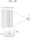
- FIGS. 9 A and 9 B are configuration diagrams schematically showing a configuration of holographic display apparatuses according to another example embodiment
- FIGS. 10 A and 10 B are configuration diagrams schematically showing a configuration of holographic display apparatuses according to another example embodiment
- FIG. 11 shows an arrangement of a plurality of prisms of a prism array of the holographic display apparatuses shown in FIGS. 10 A and 10 B ,
- FIG. 12 shows an arrangement of a plurality of pixels of a spatial light modulator of the holographic display apparatuses shown in FIGS. 10 A and 10 B .
- FIG. 13 shows the distribution of light formed on the focal plane of a Fourier lens by the holographic display apparatuses shown in FIGS. 10 A and 10 B .
- the expression, “at least one of a, b, and c,” should be understood as including only a, only b, only c, both a and b, both a and c, both b and c, or all of a, b, and c.
- FIG. 1 is a schematic diagram showing a configuration of a holographic display apparatus 100 according to an example embodiment.
- the holographic display apparatus 100 may include a spatial light modulator 120 having a plurality of pixels arranged two-dimensionally and an aperture enlargement film 130 disposed to enlarge the beam diameter of light emitted from each pixel of the spatial light modulator 120 .
- the holographic display apparatus 100 may further include a backlight unit 110 that provides coherent collimated illumination light to the spatial light modulator 120 , a Fourier lens 140 that focuses a holographic image on the space, and an image processor 150 that generates and provides a hologram data signal based on the holographic image to be reproduced to the spatial light modulator 120 .
- the Fourier lens 140 is disposed on the light entering surface of the spatial light modulator 120 , that is, between the backlight unit 110 and the spatial light modulator 120 , the position of the Fourier lens 140 is necessarily not limited thereto.
- the Fourier lens 140 may be disposed between the spatial light modulator 120 and the aperture enlargement film 130 or on the light exiting surface of the aperture enlargement film 130 .
- the backlight unit 110 may include a laser diode to provide illumination light having high coherence.
- the backlight unit 110 may include any of other light sources configured to emit light having spatial coherence.
- the backlight unit 110 may further include an optical system that enlarges light emitted from the laser diode to generate collimated parallel light having a uniform intensity distribution. Accordingly, the backlight unit 110 may provide parallel coherent illumination light having the uniform intensity distribution to the entire region of the spatial light modulator 120 .
- the spatial light modulator 120 may be configured to diffract and modulate the illumination light, according to the hologram data signal, for example, a computer-generated hologram (CGH) data signal, provided by the image processor 150 .
- the spatial light modulator 120 may use any one of a phase modulator for performing phase modulation, an amplitude modulator for performing amplitude modulation, and a complex modulator performing both phase modulation and amplitude modulation.
- the spatial light modulator 120 of FIG. 1 is a transmissive spatial light modulator, a reflective spatial light modulator may also be used.
- the spatial light modulator 120 may include a plurality of display pixels arranged two-dimensionally to display a hologram pattern for diffracting the illumination light.
- the spatial light modulator 120 may use a liquid crystal device (LCD), a semiconductor modulator, a digital micromirror device (DMD), liquid crystal on silicon (LCoS), etc.
- LCD liquid crystal device
- DMD digital micromirror device
- LCDoS
- the spatial light modulator 120 may include a two-dimensional grating-shaped black matrix and a plurality of apertures surrounded by the black matrix.
- a driving circuit for controlling the operation of each aperture is disposed below the black matrix, and each aperture is an active region that changes the intensity or phase of transmissive light or reflective light.
- the intensity or phase of light passing through each aperture or light reflected by the aperture may be adjusted under the control of the driving circuit. For example, when the spatial light modulator 120 displays the hologram pattern according to the CGH data signal provided from the image processor 150 , the intensity or phase of the illumination light may be adjusted differently in the plurality of apertures.
- the holographic image may be seen by an observer's eye E. Accordingly, the reproduced holographic image may be determined by the CGH data signal provided from the image processor 150 and the hologram pattern displayed by the spatial light modulator 120 based on the CGH data signal.
- the aperture enlargement film 130 is configured to enlarge the beam diameter of the light beam of the illumination light passing through or reflected from each aperture of the spatial light modulator 120 .
- FIG. 2 is a cross-sectional view schematically showing the configuration and operation of the aperture enlargement film 130 according to the example embodiment of the holographic display apparatus 100 shown in FIG. 1 .
- the aperture enlargement film 130 is disposed to face the light exiting surface of the spatial light modulator 120 .
- the spatial light modulator 120 includes a plurality of apertures 121 and a black matrix 122 surrounding the plurality of apertures 121 . Accordingly, a plurality of light beams transmitted from the plurality of apertures 121 of the spatial light modulator 120 respectively is incident on the aperture enlargement film 130 .
- the aperture enlargement film 130 may include a light guide layer 132 disposed to face the light exiting surface of the spatial light modulator 120 and a grating layer 133 disposed on an upper surface of the light guide layer 132 .
- the aperture enlargement film 130 may further include a substrate 131 for supporting the light guide layer 132 and the grating layer 133 such that the light guide layer 132 and the grating layer 133 do not bend.
- the substrate 131 may be omitted if the light guide layer 132 is supported without bending itself.
- the thickness of the substrate 131 is similar to the thickness of the light guide layer 132 , the light guide layer 132 may be much thinner than the substrate 131 .
- the thickness of the substrate 131 may be about 0.5 mm to about 1 mm, and the thickness of the light guide layer 132 may be about 1 ⁇ m to about 5 ⁇ m.
- the substrate 131 may include glass or a transparent polymer material of a solid material, and the light guide layer 132 may include a transparent material having a higher refractive index than the substrate 131 to transmit light therein.
- the grating layer 133 disposed on the upper surface of the light guide layer 132 may emit a portion of light incident on the grating layer 133 from the light guide layer 132 in a direction parallel a direction parallel to a direction normal to the upper surface of the grating layer 133 , which is a direction perpendicular to the upper surface of the grating layer 133 , and may reflect the remaining portion of the light incident on the grating layer 133 to travel obliquely toward the light guide layer 132 .
- the grating layer 133 may include various types of surface gratings or volume gratings.
- the surface grating may include, for example, a diffractive optical element (DOE) such as a binary phase grating, a blazed grating, etc.
- the volume grating may include, for example, a holographic optical element (HOE), a geometric phase grating, a Bragg polarization grating, a holographically formed polymer dispersed liquid crystal (H-PDLC), etc.
- HOE holographic optical element
- Such a volume grating may include periodic fine patterns of materials with different refractive indices. According to the size, height, period, duty ratio, shape, etc. of the periodic grating patterns constituting the grating layer 133 , the grating layer 133 may diffract the incident light to cause extinctive interference and constructive interference and change the traveling direction of the incident light.
- the light beam transmitted from the aperture 121 of the spatial light modulator 120 may be incident perpendicularly to the lower surface of the substrate 131 and may pass through the substrate 131 and the light guide layer 132 , and may be incident perpendicularly to the lower surface of the grating layer 133 .
- the grating layer 133 may emit a 0th order diffracted light beam among incident light beams incident perpendicularly or obliquely to the lower surface of the grating layer 133 in the direction parallel to the direction normal to the upper surface of the grating layer 133 , and may reflect a 1st order diffracted light beam to travel obliquely toward the light guide layer 132 .
- the light guide layer 132 is configured to propagate the light beam obliquely reflected from the grating layer 133 along the inside of the light guide layer 132 through total reflection. Therefore, the 1st order diffracted light beam may be totally reflected between the upper surface and the lower surface of the light guide layer 132 and travel along the inside of the light guide layer 132 . For example, as indicated by the arrow in FIG. 2 , a +1st order diffracted light beam may travel along the right direction of the light guide layer 132 , and a ⁇ 1st order diffracted light beam may travel along the left direction of the light guide layer 132 . The arrow in FIG.
- the first diffracted light beam may travel in all radial directions with respect to the incident position of the grating layer 133 .
- the 1st order diffracted light beam by the grating layer 133 is totally reflected from the lower surface of the light guide layer 132 , and again obliquely incident on the upper surface of the light guide layer 132 . Thereafter, a portion of the first diffracted light beam is totally reflected again from the upper surface of the light guide layer 132 , while the remaining portion is diffracted by the grating layer 133 , and emitted in the direction parallel to the direction normal to the upper surface of the grating layer 133 .
- the light beam emitted from the grating layer 133 includes a light beam L 0 emitted by the 0th order diffraction and a light beam L 1 emitted by the 1st order diffraction.
- the light beam L 1 emitted by the 1st order diffraction continuously surrounds the circumference of the light beam L 0 emitted by the 0th order diffraction in the shape of a ring.
- the grating layer 133 may be configured as a two-dimensional grating film capable of diffracting incident light in all directions.
- the grating layer 133 may be configured by stacking two one-dimensional grating films having orthogonal directions to each other.
- the light beam may be enlarged and emitted in the horizontal direction by the one-dimensional grating film in the horizontal direction, and the light beam may be enlarged in the vertical direction by the one-dimensional grating film in the vertical direction, and then the ring-shaped light beam L 1 may be finally emitted.
- the light beam L 1 emitted by the 1st order diffraction may overlap at least partially with the light beam L 0 emitted by the 0th order diffraction.
- the degree to which the light beam L 1 emitted by the 1st diffraction and the light beam L 0 emitted by the 0th diffraction overlap may vary according to the thickness of the light guide layer 132 .
- the light beam L 1 emitted by the 1st order diffraction may not overlap with the light beam L 0 emitted by the 0th order diffraction, and a gap may exist between the light beam L 0 emitted by the 0th order diffraction and the light beam L 1 emitted by the 1st order diffraction.
- the boundary of the light beam L 1 emitted by the 1st order diffraction coincides with the boundary of the light beam L 0 emitted by the 0th order diffraction.
- the maximum thickness of the light guide layer 132 may be selected such that the boundary of the light beam L 1 emitted by the 1st order diffraction coincides with the boundary of the light beam L 0 emitted by the 0th order diffraction.
- the light beam incident on the aperture enlargement film 130 from each aperture 121 of the spatial light modulator 120 passes through the aperture enlargement film 130 and is divided into the light beam L 0 emitted by the 0th order diffraction and the light beam L 1 emitted by the 1st order diffraction. These light beams may be combined to be viewed as one enlarged light beam.
- the aperture enlargement film 130 may enlarge the beam diameter of the light beam incident from the aperture 121 of the spatial light modulator 120 .
- the beam diameter of the light beam incident on the aperture enlargement film 130 from the aperture 121 of the spatial light modulator 120 is equal to the width W 1 of the aperture 121 .
- the beam diameter of the light beam enlarged while passing through the aperture enlargement film 130 may be the same as a beam diameter W 3 of a light beam combining the light beam L 0 emitted by the 0th order diffraction and the light beam L 1 emitted by the 1st order diffraction, and may be greater than the width W 1 of the aperture 121 of the spatial light modulator 120 .
- the beam diameter W 3 of the light beam enlarged by the aperture enlargement film 130 may vary according to the degree to which the light beam L 0 emitted by the 0th order diffraction and the light beam L 1 emitted by the 1st order diffraction overlap. As the degree of overlap is based on the thickness of the light guide layer 132 , the beam diameter W 3 of the light beam enlarged by the aperture enlargement film 130 may be determined by the thickness of the light guide layer 132 . For example, the thickness of the light guide layer 132 may be selected such that the beam diameter W 3 of the light beam enlarged by the aperture enlargement film 130 is greater than a pitch W 2 of a pixel of the spatial light modulator 120 . The pitch W 2 of the pixel of the spatial light modulator 120 is equal to the sum of the width W 1 of the aperture 121 and the width of the black matrix 122 .
- the black matrix 122 existing between the apertures 121 , there is a gap having no image information between the plurality of light beams transmitted from the plurality of apertures 121 of the spatial light modulator 120 .
- the gap between the light beams may increase the intensity of a higher order diffraction pattern.
- the aperture enlargement film 130 enlarges the beam diameter of each light beam, the intensity of the high order diffraction pattern may decrease and ultimately the high order diffraction pattern may be removed.
- the intensity of the light beam L 0 emitted by the 0th order diffraction is greater than the intensity of the light beam L 1 emitted by the 1st order diffraction. Therefore, the light beam enlarged by the aperture enlargement film 130 has a shape in which the intensity decreases from the center of the light beam to the periphery, and has a shape approximately similar to a Gaussian distribution.
- the spatial light modulator 120 may reduce high order noise generated in the focal plane of the Fourier lens 140 such that a viewing window through which a holographic image is visible may be enlarged.
- the spatial light modulator 120 is configured with an array of the plurality of apertures 121 and the black matrix 122 , a physical structure of the spatial light modulator 120 may function as a regular diffraction grating.
- the illumination light may be diffracted and interfered with by the hologram pattern formed by the spatial light modulator 120 and also by a regular structure constituting the spatial light modulator 120 .
- some of the illumination light may not be diffracted by the hologram pattern, but may pass through the spatial light modulator 120 as is.
- a plurality of lattice spots may appear on the focal plane or the pupil plane of the Fourier lens 140 on which the holographic image is converged to a point.
- the plurality of lattice spots may function as image noise that degrades quality of the reproduced holographic image and makes it uncomfortable to observe the holographic image.
- a 0th order noise formed by the illumination light which is not diffracted may appear on an axis of the Fourier lens 140 .
- multiple high order noise of a regular lattice pattern may appear around a 0th order noise by interference between light diffracted by the regular pixel structure of the spatial light modulator 120 .
- the multiple high order noise having the regular lattice structure may be reduced to enlarge a viewing window.
- FIG. 3 A shows the intensity distribution of illumination light transmitted through the aperture 121 of the spatial light modulator 120 without the aperture enlargement film 130
- FIGS. 3 B and 3 C show a light intensity distribution formed by the illumination light of FIG. 3 A on the focal plane of the Fourier lens 140
- FIG. 3 B shows the light intensity distribution formed by one pixel
- FIG. 3 C shows the light intensity distribution formed when a plurality of adjacent pixels are simultaneously turned on.
- graph B indicates the intensity distribution of the illumination light of a uniform distribution transmitted through the aperture 121 of the spatial light modulator 120 , and has a uniform distribution across the width W 1 of the aperture 121 .
- graph A indicates the intensity distribution when the illumination light of the uniform distribution indicated by graph B passes through a Gaussian apodization filter, and shows a Gaussian distribution.
- the beam diameter of the illumination light transmitted through the aperture 121 of the spatial light modulator 120 is substantially the same as the width W 1 of the aperture 121 of the spatial light modulator 120 .
- the beam diameter of the illumination light transmitted through the aperture 121 of the spatial light modulator 120 is also smaller than the pixel period of the spatial light modulator 120 .
- the graph A in FIG. 3 B showing the light intensity distribution formed by one pixel shows an intensity distribution after the illumination light having the Gaussian distribution indicated by graph A in FIG. 3 A expands on the focal plane of the Fourier lens 140 due to the diffraction phenomenon by the aperture 121 of the spatial light modulator 120 .
- a graph B in FIG. 3 B shows a light intensity distribution formed on the focal plane of the Fourier lens 140 due to the diffraction when the illumination light having the uniform intensity distribution indicated by graph B in FIG. 3 A passes through the aperture 121 of one pixel of the spatial light modulator 120 .
- the graph B in FIG. 3 C showing the light intensity distribution formed on the focal plane of the Fourier lens 140 by a plurality of adjacent pixels shows a light intensity distribution formed on the focal plane of the Fourier lens 140 due to the diffraction when the illumination light having the uniform intensity distribution indicated by graph B in FIG. 3 A passes through the apertures 121 of the plurality of adjacent pixels of the spatial light modulator 120 .
- the central peak of the graph B in FIG. 3 C is generated by the 0 th order diffraction, and surrounding peaks are generated by high order diffraction of ⁇ 1st order or higher. Accordingly, an interference pattern formed by the illumination light having the Gaussian distribution indicated by graph A in FIG. 3 A may be the same as the product of the graph A in FIG.
- FIG. 3 D shows the distribution of light formed in the focal plane of the Fourier lens 140 by a holographic display apparatus according to the related example shown in FIG. 3 A .
- the holographic display apparatus according to the related example may have a structure without the aperture enlargement film 130 in the configuration shown in FIG. 1 .
- 0th order noise N 0 due to 0th order diffraction is formed on the center of the focal plane, that is, on the optical axis.
- high order noises N 1 generated by high order diffraction of ⁇ 1st order or higher are regularly formed in the form of a lattice.
- a rectangle indicated by a thick solid line surrounded by the high order noises N 1 becomes a viewing window of the holographic display apparatus determined by the resolution of the spatial light modulator 120 .
- a holographic image may be reproduced via an off-axis technique such that the spot of the holographic image is reproduced by avoiding the multiple noises N 0 and N 1 . Because the multiple noises N 0 and N 1 are generated by the physical internal structure of the spatial light modulator 120 and are independent of the hologram pattern displayed by the spatial light modulator 120 , the positions of the noises N 0 and N 1 are always fixed.
- a holographic pattern may be formed such that the holographic image is reproduced on a position that does not include the multiple noises N 0 and N 1 .
- the image processor 150 may add a prism phase to CGH data including holographic image information. Then, the holographic image may be reproduced away from the optical axis by a prism pattern displayed together with the hologram pattern by the spatial light modulator 120 . Therefore, the reproduced holographic image may be away from the 0th order noise N 0 .
- a holographic image signal S may be positioned slightly away from the 0th order noise N 0 in a diagonal direction by using an off-axis technique.
- a complex conjugate image signal S* may be generated in the opposite direction of the holographic image signal S with respect to the 0th order noise N 0 .
- the holographic image signal S may not be positioned farther away than the high order noise N 1 as shown in FIG. 3 D .
- the high order noise N 1 makes it difficult to enlarge the viewing window and interferes with the viewing of the holographic image.
- holographic image signals S 1 by a high order diffraction in the diagonal direction with respect to the high order noises N 1 and their complex conjugate image signals S 1 * may be generated together.
- the holographic image signal S 1 by the high order diffraction and its complex conjugate image signal S 1 * may also interfere with the viewing of the holographic image.
- FIG. 4 A shows an intensity distribution of illumination light transmitted through the aperture 121 of the spatial light modulator 120 and the aperture enlargement film 130 .
- FIGS. 4 B to 4 D show light intensity distributions that the illumination light of FIG. 4 A forms on the focal plane of the Fourier lens 140 .
- FIG. 4 B shows the light intensity distribution formed by one pixel
- FIG. 4 C shows the light intensity distribution formed when a plurality of adjacent pixels are simultaneously turned on
- FIG. 4 D shows a light intensity distribution formed on the focal plane of the Fourier lens 140 due to the diffraction of the illumination light transmitted through the aperture 121 of the spatial light modulator 120 and the aperture enlargement film 130 .
- graph B indicates the intensity distribution of the illumination light transmitted through the aperture 121 of the spatial light modulator 120
- a graph C indicates the intensity distribution of the illumination light transmitted through the aperture 121 of the spatial light modulator 120 and the aperture enlargement film 130 .
- the intensity of the illumination light transmitted through the aperture 121 of the spatial light modulator 120 and the aperture enlargement film 130 has the Gaussian distribution.
- the beam diameter of the illumination light may be greater than the width W 1 of the aperture 121 of the spatial light modulator 120 and may be greater than the pixel period of the spatial light modulator 120 .
- the aperture enlargement film 130 may provide an effect such as enlarging the aperture 121 of the spatial light modulator 120 .
- the graph B in FIG. 4 B showing the light intensity distribution formed by one pixel is the same as the graph B in FIG. 3 B .
- the graph B in FIG. 4 B is the light intensity distribution formed on the focal plane of the Fourier lens 140 due to the diffraction of the illumination light having a uniform intensity distribution that passes through the aperture 121 of the spatial light modulator 120 but does not pass through the aperture enlargement film 130 .
- the graph C in FIG. 4 B shows the light intensity distribution formed by the illumination light having the intensity distribution indicated by graph C in FIG. 4 A on the focal plane of the Fourier lens 140 without considering interference.
- the illumination light having the intensity distribution indicated by graph C in FIG. 4 A is rarely enlarged on the focal plane of the Fourier lens 140 , as shown in FIG. 4 B , due to an optical effect such that the aperture 121 of the spatial light modulator 120 is enlarged.
- the graph B in FIG. 4 C showing the light intensity distribution formed on the focal plane of the Fourier lens 140 by a plurality of adjacent pixels is the light intensity distribution formed on the focal plane of the Fourier lens 140 due to the diffraction when the illumination light having a uniform intensity distribution indicated by graph B in FIG. 4 A passes through the apertures 121 of the plurality of adjacent pixels of the spatial light modulator 120 .
- the central peak of the graph B in FIG. 3 C is generated by the 0 th order diffraction, and surrounding peaks are generated by high order diffraction of ⁇ 1st order or higher.
- An interference pattern formed by the illumination light having the Gaussian distribution indicated by graph C in FIG. 4 A may be the same as the product of the graph C in FIG. 4 B and the graph B in FIG. 4 C , and is indicated by a graph D in FIG. 4 D .
- the distribution of the graph C in FIG. 4 B may include only peak due to a 0th order diffraction of the graph B in FIG. 4 C , as shown in FIG. 4 C . Therefore, when using the illumination light of a wide beam diameter having the Gaussian distribution indicated by graph C in FIG. 4 A , as shown in FIG. 4 D , only the interference pattern due to the 0th order diffraction occurs, and an interference pattern due to a high order diffraction does not appear.
- FIG. 4 E shows the distribution of light formed on the focal plane of the Fourier lens 140 by the holographic display apparatus according 100 of FIG. 4 A .
- the focal plane of the Fourier lens 140 on the focal plane of the Fourier lens 140 , only the 0 th order noise N 0 , the holographic image signal S, and the complex conjugate image signal S* appear, and the high order noises N 1 , the holographic image signals S 1 by the high order diffraction and their complex conjugate image signals S 1 * illustrated in FIG. 3 D hardly appear. Therefore, by using the aperture enlargement film 130 , the observer may view the holographic image without being disturbed by the high order noise N 1 and in a wider region.
- FIG. 5 is a cross-sectional view schematically showing the configuration and operation of an aperture enlargement film 130 a according to another example embodiment.
- the aperture enlargement film 130 a may include a first grating layer 133 a disposed to face the light exiting surface of the spatial light modulator 120 , the light guide layer 132 disposed on the first grating layer 133 a , and a second grating layer 133 b disposed on the light guide layer 132 .
- the light guide layer 132 is disposed between the first grating layer 133 a and the second grating layer 133 b .
- the first grating layer 133 a and the second grating layer 133 b may include various types of surface gratings or volume gratings.
- the first grating layer 133 a and the second grating layer 133 b may have different periodic grating patterns in the size, height, period, duty ratio, and shape from the grating layer 133 illustrated in FIG. 2 .
- the aperture enlargement film 130 a may be disposed such that the first grating layer 133 a faces the light exiting surface of the spatial light modulator 120 .
- a light beam transmitted from the aperture 121 of the spatial light modulator 120 is first incident perpendicularly on the lower surface of the first grating layer 133 a .
- the first grating layer 133 a may be configured to diffract an incident light that is incident perpendicularly on the lower surface.
- the first grating layer 133 a may be configured to 0th diffract a portion of the incident light that is incident perpendicularly on the lower surface and travel in a direction parallel to the direction normal to the upper surface.
- the traveling direction of a light beam that is 0th diffracted by the first grating layer 133 a does not change.
- the first grating layer 133 a may be configured to 1st diffract a portion of the incident light that is incident perpendicularly on the lower surface and travel in an inclined direction with respect to the upper surface.
- the light beam that is 0th diffracted by the first grating layer 133 a may be incident perpendicularly on the upper surface of the light guide layer 132 , and the light beam that is 1st diffracted may be obliquely incident on the upper surface of the light guide layer 132 .
- the second grating layer 133 b is disposed on the upper surface of the light guide layer 132 .
- the second grating layer 133 b may be configured to propagate a portion of the incident light that is incident on the lower surface in the direction parallel to the direction normal to the upper surface.
- the light beam perpendicularly incident on the upper surface of the light guide layer 132 from the first grating layer 133 a is emitted through the second grating layer 133 b without changing the traveling direction.
- a portion of the light beam obliquely incident on the upper surface of the light guide layer 132 from the first grating layer 133 a is emitted in the direction parallel to the direction normal to the upper surface of the second grating layer 133 b through the second grating layer 133 b .
- the remaining portion of the light beam obliquely incident on the upper surface of the light guide layer 132 from the first grating layer 133 a is totally reflected from the upper surface of the light guide layer 132 and travels in a lateral direction along the inside of the light guide layer 132 .
- a portion of the light beam is emitted through the second grating layer 133 b whenever the light beam is incident on the upper surface of the light guide layer 132 .
- the light beam incident on the aperture enlargement film 130 a is divided into a plurality of light beams ⁇ L 2 , ⁇ L 1 , L 0 , +L 1 , and +L 2 and is emitted from the aperture enlargement film 130 a .
- the thickness of the light guide layer 132 may be selected such that the plurality of light beams ⁇ L 2 , ⁇ L 1 , L 0 , +L 1 , and +L 2 overlap at least partially. Then, the plurality of light beams ⁇ L 2 , ⁇ L 1 , L 0 , +L 1 , and +L 2 emitted from the aperture enlargement film 130 a may be viewed as one enlarged light beam.
- the aperture enlargement film 130 a may enlarge the beam diameter of the light beam incident from the aperture 121 of the spatial light modulator 120 .
- the intensity of the light beam L 0 is greater than the intensity of the surrounding light beams ⁇ L 1 and +L 1
- the intensity of the light beams ⁇ L 1 and +L 1 is greater than the intensity of the surrounding light beams ⁇ L 2 and +L 2
- the light beam enlarged by the aperture enlargement film 130 a may have a shape similar to the Gaussian distribution in which the intensity decreases from the center to the periphery.
- FIG. 6 is a cross-sectional view schematically showing the configuration and operation of an aperture enlargement film 130 b according to another example embodiment.
- the aperture enlargement film 130 b may include a third grating layer 133 c , the light guide layer 132 , and a fourth grating layer 133 d .
- the light guide layer 132 is disposed between the third grating layer 133 c and the fourth grating layer 133 d .
- the third grating layer 133 c and the fourth grating layer 133 d may have different periodic grating patterns in the size, height, period, duty ratio, and shape from the first and second grating layers 133 a and 133 b shown in FIG. 5 .
- the aperture enlargement film 130 b may be disposed such that the third grating layer 133 c faces the light exiting surface of the spatial light modulator 120 . Then, a light beam transmitted from each aperture 121 of the spatial light modulator 120 is first incident perpendicularly on the lower surface of the third grating layer 133 c .
- the third grating layer 133 c may be configured to transmit an incident light that is incident perpendicularly on the lower surface as is. Accordingly, the light beam incident on the lower surface of the third grating layer 133 c may be incident perpendicularly on the lower surface of the fourth grating layer 133 d through the light guide layer 132 .
- the third grating layer 133 c may be configured to reflect a portion of an incident light obliquely incident on the upper surface in a direction perpendicular to the upper surface.
- the fourth grating layer 133 d may 0th and 1st diffract the incident light perpendicularly incident on the lower surface to travel in different directions.
- the light beam that is 0th diffracted by the fourth grating layer 133 d may be emitted in a direction parallel to the direction normal to the upper surface of the fourth grating layer 133 d , and the light beam that is 1st diffracted may obliquely travel toward the light guide layer 132 .
- the light beam that is 1st diffracted by the fourth grating layer 133 d travels in a lateral direction inside the light guide layer 132 through total reflection.
- a portion of the light beam may be diffracted by the upper surface of the third grating layer 133 c and again be incident perpendicularly on the lower surface of the fourth grating layer 133 d .
- the light beam incident on the aperture enlargement film 130 b from the spatial light modulator 120 is divided into the plurality of light beams ⁇ L 2 , ⁇ L 1 , L 0 , +L 1 , and +L 2 in this manner, and is output from the aperture enlargement film 130 b.
- FIG. 7 is a cross-sectional view schematically showing the configuration and operation of an aperture enlargement film 130 c according to another example embodiment.
- the aperture enlargement film 130 c may include a fifth grating layer 133 e , a fourth grating layer 133 d , and the light guide layer 132 disposed between the fifth grating layer 133 e and the fourth grating layer 133 d.
- a light beam transmitted from each aperture 121 of the spatial light modulator 120 is first incident perpendicularly on the lower surface of the fifth grating layer 133 e .
- the fifth grating layer 133 e may be configured to 0th diffract a portion of the incident light that is incident perpendicularly on the lower surface and travel in a direction parallel to the direction normal to the upper surface of the fifth grating layer 133 e .
- the fifth grating layer 133 e may be configured to 1st diffract a portion of the incident light that is incident perpendicularly on the lower surface and travel in an inclined direction with respect to the upper surface of the fifth grating layer 133 e .
- the light beam that is 0th diffracted by the fifth grating layer 133 e may be incident perpendicularly on the lower surface of the fourth grating layer 133 d , and the light beam that is 1st diffracted may be obliquely incident on the upper surface of the light guide layer 132 .
- the fifth grating layer 133 e may be configured to diffract a portion of the incident light that is obliquely incident on the upper surface and travel in the direction parallel to the direction normal to the upper surface.
- the fifth grating layer 133 e illustrated in FIG. 7 and the first grating layer 133 a illustrated in FIG. 5 in that the 0th order diffracted light in the incident light incident perpendicularly on the lower surface travels in the direction perpendicular to the upper surface, and the 1st order diffracted light travels in the inclined direction with respect to the upper surface.
- the first grating layer 133 a is different from the fifth grating layer 133 e in that the first grating layer 133 a does not diffract the incident light obliquely incident on the upper surface in the direction normal to the upper surface.
- the third grating layer 133 c illustrated in FIG. 6 is different from the fifth grating layer 133 e in that the incident light incident perpendicularly on the lower surface does not travel in the inclined direction with respect to the upper surface.
- the fifth grating layer 133 e may have a periodic grating pattern different from the first grating layer 133 a and the third grating layer 133 c in the size, height, period, duty ratio, shape, etc.
- the fourth grating layer 133 d illustrated in FIG. 7 is the same as the fourth grating layer 133 d illustrated in FIG. 6 . Accordingly, a portion of the incident light incident perpendicularly on the lower surface of the fourth grating layer 133 d is emitted in the direction parallel to the direction normal to the upper surface, and the remaining portion obliquely travels in the lateral direction along the light guide layer 132 . In a process of traveling inside the light guide layer 132 in the lateral direction through total reflection, a portion of the light beam may be diffracted by the upper surface of the fifth grating layer 133 e and again incident perpendicularly on the lower surface of the fourth grating layer 133 d .
- the light beam incident on the aperture enlargement film 130 c from the spatial light modulator 120 is divided into a plurality of light beams ⁇ L 3 , ⁇ L 2 , ⁇ L 1 , L 0 , +L 1 , +L 2 , and +L 3 in this manner, and is output from the aperture enlargement film 130 c.
- FIG. 8 is a cross-sectional view schematically showing the configuration and operation of an aperture enlargement film 130 d according to another example embodiment.
- the aperture enlargement film 130 d may include the fifth grating layer 133 e and the light guide layer 132 disposed on the upper surface of the fifth grating layer 133 e .
- the aperture enlargement film 130 d may be disposed such that the fifth grating layer 133 e faces the light exiting surface of the spatial light modulator 120 .
- the aperture enlargement film 130 d may further include the substrate 131 for supporting the fifth grating layer 133 e and the light guide layer 132 such that the light guide layer 132 and the fifth grating layer 133 e do not bend.
- the substrate 131 may be disposed on the lower surface of the fifth grating layer 133 e.
- the fifth grating layer 133 e illustrated in FIG. 8 is the same as the fifth grating layer 133 e illustrated in FIG. 5 . Therefore, a portion of a light beam transmitted from each aperture 121 of the spatial light modulator 120 is 0th order diffracted on the lower surface of the fifth grating layer 133 e and is perpendicularly incident on the lower surface of the light guide layer 132 .
- the light beam perpendicularly incident on the lower surface of the light guide layer 132 passes through the light guide layer 132 as is, and is emitted in a direction normal to the upper surface of the light guide layer 132 .
- the remaining portion of the light beam transmitted from each aperture 121 of the spatial light modulator 120 is 1st diffracted on the lower surface of the fifth grating layer 133 e and obliquely travels in the lateral direction along the light guide layer 132 .
- a portion of the light beam may be diffracted by the upper surface of the fifth grating layer 133 e and again be incident perpendicularly on the lower surface of the light guide layer 132 .
- the light beam incident on the aperture enlargement film 130 d from the spatial light modulator 120 is divided into the plurality of light beams ⁇ L 2 , ⁇ L 1 , L 0 , +L 1 , and +L 2 in this way, and is output from the aperture enlargement film 130 d.
- FIG. 9 A is a configuration diagram schematically showing a configuration of a holographic display apparatus 200 according to another example embodiment.
- the holographic display apparatus 200 includes all of the components of the holographic display apparatus 100 shown in FIG. 1 , and may further include a Gaussian apodization filter array 210 which is disposed to face the light exiting surface of the spatial light modulator 120 .
- the Gaussian apodization filter array 210 may be disposed between the spatial light modulator 120 and the aperture enlargement film 130 .
- the backlight unit 110 provides a collimated uniform coherent illumination light to the spatial light modulator 120 .
- the illumination light incident on the spatial light modulator 120 has a uniform intensity distribution.
- a light beam passing through the aperture 121 of the spatial light modulator 120 also has a uniform intensity distribution.
- the intensity distribution of the light beam enlarged by the aperture enlargement film 130 may be a stepwise distribution, not a curved Gaussian distribution.
- the Gaussian apodization filter array 210 may be configured to convert the uniform intensity distribution of the light beam emitted from the aperture 121 of the spatial light modulator 120 into the curved Gaussian distribution.
- the Gaussian apodization filter array 210 may include a plurality of Gaussian apodization filters arranged two-dimensionally.
- the Gaussian apodization filters may correspond one-to-one with the apertures 121 of the spatial light modulator 120 , respectively. Then, the intensity of each light beam that passes through the Gaussian apodization filter array 210 and is incident on the aperture enlargement film 130 may have the curved Gaussian distribution. Therefore, the intensity distribution of each light beam enlarged by the aperture enlargement film 130 may also have the curved Gaussian distribution.
- the Gaussian apodization filter may be a reverse apodizing filter with light reflection coating or light absorption coating.
- the light reflection coating or the light absorption coating may be formed to have the highest transmittance in the center and a transmittance that gradually reduces in the radial direction such that the intensity distribution of a transmitted light may have a Gaussian profile.
- the Gaussian apodization filter may be formed by coating a reflective metal such that the coating thickness gradually increases from the center toward the periphery in the radial direction.
- the size of the Gaussian apodization filter may be the same as the pixel size of the spatial light modulator 120 .
- the Gaussian apodization filter array 210 may be provided in the form of a separate layer or a separate film, but may be integrally formed with a color filter array of the spatial light modulator 120 .
- the Gaussian apodization filter array 210 may be integrally formed on the surface of the color filter array by coating the reflective metal on the surface of each color filter corresponding to each pixel of the spatial light modulator 120 in the manner as described above.
- FIG. 9 B is a configuration diagram schematically showing a configuration of a holographic display apparatus 200 a according to another example embodiment.
- the holographic display apparatus 200 a includes all of the components of the holographic display apparatus 100 shown in FIG. 1 , and may further include the Gaussian apodization filter array 210 which is disposed to face the light entering surface of the spatial light modulator 120 .
- the Gaussian apodization filter array 210 may be disposed between the backlight unit 110 and the spatial light modulator 120 .
- the holographic display apparatus 200 a shown in FIG. 9 B differs only in the position of the Gaussian apodization filter array 210 .
- the Gaussian apodization filter array 210 generates an illumination light of a uniform intensity emitted from the backlight unit 110 into a plurality of light beams having an intensity distribution in the form of a Gaussian distribution.
- a plurality of light beams having the intensity distribution in the form of the Gaussian distribution may be respectively incident on the corresponding apertures 121 of the spatial light modulator 120 .
- each light beam passing through the aperture 121 of the spatial light modulator 120 and incident on the aperture enlargement film 130 may have an intensity of a curved Gaussian distribution. Therefore, the intensity distribution of each light beam enlarged by the aperture enlargement film 130 may also have a curved Gaussian distribution.
- FIG. 10 A is a configuration diagram schematically showing a configuration of a holographic display apparatus 300 according to another example embodiment.
- the holographic display apparatus 300 includes all of the components of the holographic display apparatus 200 shown in FIG. 9 A , and may further include a prism array 310 .
- the prism array 310 may be disposed between the Gaussian apodization filter array 210 and the aperture enlargement film 130 .
- the Gaussian apodization filter array 210 may be disposed to face the light entering surface of the spatial light modulator 120 as shown in FIG. 9 B or may be omitted as shown in FIG. 1 .
- the prism array 310 may be disposed between the spatial light modulator 120 and the aperture enlargement film 130 .
- FIG. 10 B is a configuration diagram schematically showing a configuration of a holographic display apparatus 300 a according to another example embodiment.
- the holographic display apparatus 300 a shown in FIG. 10 B differs only in the position of the prism array 310 .
- the prism array 310 may be disposed to face the light exiting surface of the aperture enlargement film 130 .
- the prism array 310 may include a plurality of prisms that allow incident light to travel in different directions.
- FIG. 11 shows an arrangement of a plurality of prisms P 1 , P 2 , and P 3 of the prism array 310 of the holographic display apparatuses 300 and 300 a shown in FIGS. 10 A and 10 B .
- the prism array 310 may be divided into a plurality of unit regions 310 a arranged two-dimensionally. Each unit region 310 a may include the plurality of prisms P 1 , P 2 , and P 3 that allow incident light to travel in different directions.
- the prism array 310 may include the plurality of prisms P 1 , P 2 , and P 3 arranged repeatedly.
- the first prism P 1 may be configured to change the traveling direction of the incident light to a first direction
- the second prism P 2 may be configured to change the traveling direction of the incident light to a second direction different from the first direction
- the third prism P 3 may be configured to change the traveling direction of the incident light in a third direction different from the first and second directions.
- each unit region 310 a includes prisms of a 1 ⁇ 3 arrangement, but is not necessarily limited thereto.
- the prism arrangement in each unit region 310 a may be differently selected according to the number of holographic images of different viewpoints simultaneously provided by the holographic display apparatuses 300 and 300 a .
- each unit region 310 a may include prisms of a 1 ⁇ 4 arrangement.
- each unit region 310 a may include prisms of a 2 ⁇ 2 arrangement.
- Each of the prisms P 1 , P 2 , and P 3 of the prism array 310 may correspond one-to-one with each pixel of the spatial light modulator 120 .
- FIG. 12 shows an arrangement of a plurality of pixels of the spatial light modulator 120 of the holographic display apparatuses 300 and 300 a shown in FIGS. 10 A and 10 B .
- the spatial light modulator 120 includes the plurality of pixels that are two-dimensionally arranged.
- the spatial light modulator 120 may include a plurality of unit regions 120 a arranged two-dimensionally.
- the unit regions 120 a of the spatial light modulator 120 may have the same arrangement form as the unit regions 310 a of the prism array 310 .
- the unit region 120 a of the spatial light modulator 120 may include pixels X 1 , X 2 , and X 3 of the 1 ⁇ 3 arrangement.
- the plurality of pixels X 1 , X 2 , and X 3 may operate to reproduce holographic images having different viewpoints.
- the first pixel X 1 may operate to reproduce a holographic image of a first viewpoint
- the second pixel X 2 may operate to reproduce a holographic image of a second viewpoint different from the first viewpoint
- the third pixel X 3 may operate to reproduce a holographic image of a third viewpoint different from the first and second viewpoints.
- the image processor 150 may be configured to provide a first hologram data signal for the holographic image of the first viewpoint to the first pixel X 1 , a second hologram data signal for the holographic image of the second viewpoint to the second pixel X 2 , and a third hologram data signal for the holographic image of the third viewpoint to the third pixel X 3 .
- each unit region 120 a only includes the pixels of the 1 ⁇ 3 arrangement, but is not necessarily limited thereto.
- the pixel arrangement in each unit region 120 a may be differently selected according to the number of holographic images of different viewpoints to be simultaneously provided by the holographic display apparatuses 300 and 300 a .
- each unit region 120 a only includes pixels of a 1 ⁇ 4 arrangement.
- each unit region 120 a may include pixels of a 2 ⁇ 2 arrangement.
- the first pixel X 1 may be disposed to face the first prism P 1
- the second pixel X 2 may be disposed to face the second prism P 2
- the third pixel X 3 may be disposed to face the third prism P 3 .
- the holographic image of the first viewpoint reproduced through the first pixel X 1 travels in the first direction by the first prism P 1
- the holographic image of the second viewpoint reproduced through the second pixel X 2 travels in the second direction by the second prism P 2
- the holographic image of the third viewpoint reproduced through the third pixel X 3 travels in the third direction by the third prism P 3 .
- three holographic images having different viewpoints are focused on the focal plane of the Fourier lens 140 at different positions.
- FIG. 13 shows the distribution of light formed on the focal plane of the Fourier lens 140 by the holographic display apparatuses 300 and 300 a shown in FIGS. 10 A and 10 B .
- the 0th order noise N 0 appears in the center of the focal plane of the Fourier lens 140 .
- a square indicated by a solid line is a boundary of a viewing window determined by a pixel period of the spatial light modulator 120 .
- using the aperture enlargement film 130 may prevent the high order noise N 1 from appearing along the boundary of the viewing window.
- first holographic image signal S 1 by the first pixel X 1 and the first prism P 1 the second holographic image signal S 2 by the second pixel X 2 and the second prism P 2
- the third holographic image signal S 3 by the third pixel X 3 and the third prism P 3 appear.
- first complex conjugate image signal S 1 *, the second complex conjugate image signal S 2 *, and the third complex conjugate image signal S 3 * appear at symmetrical positions with respect to the first holographic image signal S 1 , the second holographic image signal S 2 , and the third holographic image signal S 3 around on the 0th order noise N 0 .
- the first holographic image signal S 1 whose travel direction changes by the first prism P 1 and the third holographic image signal S 3 whose travel direction changes by the third prism P 3 may be located outside the boundary of the viewing window determined by the pixel period of the spatial light modulator 120 .
- using the prism array 310 may further enlarge the viewing window determined by the pixel period of the spatial light modulator 120 beyond the limit range of the viewing window, and an observer may view the holographic image in a wider region Further, because the high order noise N 1 does not appear between the first holographic image signal S 1 and the second holographic image signal S 2 and between the second holographic image signal S 2 and the third holographic image signal S 3 , when the observer's eye E moves from the first holographic image signal S 1 to the second holographic image signal S 2 or from the second holographic image signal S 2 to the third holographic image signal S 3 , the observer may view a holographic image of a naturally changed viewpoint without being disturbed by high order noise N 1 .
Abstract
Description
Claims (16)
Priority Applications (1)
| Application Number | Priority Date | Filing Date | Title |
|---|---|---|---|
| US18/369,039 US20240004346A1 (en) | 2019-12-11 | 2023-09-15 | Holographic display apparatus for providing expanded viewing window |
Applications Claiming Priority (4)
| Application Number | Priority Date | Filing Date | Title |
|---|---|---|---|
| KR20190164803 | 2019-12-11 | ||
| KR10-2019-0164803 | 2019-12-11 | ||
| KR1020200039707A KR20210074157A (en) | 2019-12-11 | 2020-04-01 | Holographic display apparatus providing expanded viewing window |
| KR10-2020-0039707 | 2020-04-01 |
Related Child Applications (1)
| Application Number | Title | Priority Date | Filing Date |
|---|---|---|---|
| US18/369,039 Continuation US20240004346A1 (en) | 2019-12-11 | 2023-09-15 | Holographic display apparatus for providing expanded viewing window |
Publications (2)
| Publication Number | Publication Date |
|---|---|
| US20210181678A1 US20210181678A1 (en) | 2021-06-17 |
| US11796960B2 true US11796960B2 (en) | 2023-10-24 |
Family
ID=73343963
Family Applications (2)
| Application Number | Title | Priority Date | Filing Date |
|---|---|---|---|
| US17/011,080 Active 2041-02-14 US11796960B2 (en) | 2019-12-11 | 2020-09-03 | Holographic display apparatus for providing expanded viewing window |
| US18/369,039 Pending US20240004346A1 (en) | 2019-12-11 | 2023-09-15 | Holographic display apparatus for providing expanded viewing window |
Family Applications After (1)
| Application Number | Title | Priority Date | Filing Date |
|---|---|---|---|
| US18/369,039 Pending US20240004346A1 (en) | 2019-12-11 | 2023-09-15 | Holographic display apparatus for providing expanded viewing window |
Country Status (3)
| Country | Link |
|---|---|
| US (2) | US11796960B2 (en) |
| EP (1) | EP3835878A1 (en) |
| CN (1) | CN112946911A (en) |
Citations (16)
| Publication number | Priority date | Publication date | Assignee | Title |
|---|---|---|---|---|
| US5760885A (en) * | 1994-12-04 | 1998-06-02 | Seiko Epson Corporation | Light-sensing device |
| US6137555A (en) * | 1997-03-26 | 2000-10-24 | Matsushita Electronics Corporation | Liquid crystal panel with uniform adhesive layer and method of manufacturing |
| US20020122015A1 (en) * | 2000-12-15 | 2002-09-05 | Song Young-Ran | Wearable display system |
| US20110075257A1 (en) | 2009-09-14 | 2011-03-31 | The Arizona Board Of Regents On Behalf Of The University Of Arizona | 3-Dimensional electro-optical see-through displays |
| US8040589B2 (en) * | 2008-02-12 | 2011-10-18 | Qualcomm Mems Technologies, Inc. | Devices and methods for enhancing brightness of displays using angle conversion layers |
| US20120099194A1 (en) * | 2009-06-19 | 2012-04-26 | Koninklijke Philips Electronics N.V. | Multi-view device for generating animations or three dimensional images |
| US20160327906A1 (en) * | 2014-01-07 | 2016-11-10 | Seereal Technologies S.A. | Display device for holographic reconstruction |
| KR20170072114A (en) | 2015-12-16 | 2017-06-26 | 한국전자통신연구원 | Apparatus and method for digital holographic display with structure of totally internal reflection |
| US20180120563A1 (en) | 2016-11-01 | 2018-05-03 | Microsoft Technology Licensing, Llc | Holographic projector for waveguide display |
| US20180129166A1 (en) | 2016-11-10 | 2018-05-10 | Samsung Electronics Co., Ltd. | Holographic display apparatus for providing expanded viewing window |
| US10133077B2 (en) * | 2015-11-05 | 2018-11-20 | Seiko Epson Corporation | Luminous flux diameter enlarging element and display apparatus |
| US20180364641A1 (en) | 2017-06-20 | 2018-12-20 | Korea Advanced Institute Of Science And Technology | Apparatus and method for forming 3-dimensional holographic image using aperiodically structured optical elements |
| KR20180138111A (en) | 2017-06-20 | 2018-12-28 | 한국과학기술원 | Apparatus and method for forming 3 dimensional holographic image using non-periodically structured optical elements |
| US10210823B2 (en) | 2016-01-13 | 2019-02-19 | Samsung Electronics Co., Ltd. | Light deflector and display apparatus |
| US20190171007A1 (en) | 2016-07-19 | 2019-06-06 | The Board Of Trustees Of The University Of Illinois | Method and system for near-eye three dimensional display |
| US20210026298A1 (en) | 2019-07-25 | 2021-01-28 | Samsung Electronics Co., Ltd. | Holographic display apparatus and method for providing expanded viewing window |
-
2020
- 2020-09-03 US US17/011,080 patent/US11796960B2/en active Active
- 2020-11-06 CN CN202011229878.4A patent/CN112946911A/en active Pending
- 2020-11-11 EP EP20207005.8A patent/EP3835878A1/en active Pending
-
2023
- 2023-09-15 US US18/369,039 patent/US20240004346A1/en active Pending
Patent Citations (17)
| Publication number | Priority date | Publication date | Assignee | Title |
|---|---|---|---|---|
| US5760885A (en) * | 1994-12-04 | 1998-06-02 | Seiko Epson Corporation | Light-sensing device |
| US6137555A (en) * | 1997-03-26 | 2000-10-24 | Matsushita Electronics Corporation | Liquid crystal panel with uniform adhesive layer and method of manufacturing |
| US20020122015A1 (en) * | 2000-12-15 | 2002-09-05 | Song Young-Ran | Wearable display system |
| US8040589B2 (en) * | 2008-02-12 | 2011-10-18 | Qualcomm Mems Technologies, Inc. | Devices and methods for enhancing brightness of displays using angle conversion layers |
| US20120099194A1 (en) * | 2009-06-19 | 2012-04-26 | Koninklijke Philips Electronics N.V. | Multi-view device for generating animations or three dimensional images |
| US20110075257A1 (en) | 2009-09-14 | 2011-03-31 | The Arizona Board Of Regents On Behalf Of The University Of Arizona | 3-Dimensional electro-optical see-through displays |
| US20160327906A1 (en) * | 2014-01-07 | 2016-11-10 | Seereal Technologies S.A. | Display device for holographic reconstruction |
| US10133077B2 (en) * | 2015-11-05 | 2018-11-20 | Seiko Epson Corporation | Luminous flux diameter enlarging element and display apparatus |
| KR20170072114A (en) | 2015-12-16 | 2017-06-26 | 한국전자통신연구원 | Apparatus and method for digital holographic display with structure of totally internal reflection |
| US10210823B2 (en) | 2016-01-13 | 2019-02-19 | Samsung Electronics Co., Ltd. | Light deflector and display apparatus |
| US20190171007A1 (en) | 2016-07-19 | 2019-06-06 | The Board Of Trustees Of The University Of Illinois | Method and system for near-eye three dimensional display |
| US20180120563A1 (en) | 2016-11-01 | 2018-05-03 | Microsoft Technology Licensing, Llc | Holographic projector for waveguide display |
| US20180129166A1 (en) | 2016-11-10 | 2018-05-10 | Samsung Electronics Co., Ltd. | Holographic display apparatus for providing expanded viewing window |
| KR20180138111A (en) | 2017-06-20 | 2018-12-28 | 한국과학기술원 | Apparatus and method for forming 3 dimensional holographic image using non-periodically structured optical elements |
| US20180364641A1 (en) | 2017-06-20 | 2018-12-20 | Korea Advanced Institute Of Science And Technology | Apparatus and method for forming 3-dimensional holographic image using aperiodically structured optical elements |
| US20210026298A1 (en) | 2019-07-25 | 2021-01-28 | Samsung Electronics Co., Ltd. | Holographic display apparatus and method for providing expanded viewing window |
| KR20210012484A (en) | 2019-07-25 | 2021-02-03 | 삼성전자주식회사 | Holographic display apparatus and method for providing expanded viewing window |
Non-Patent Citations (2)
| Title |
|---|
| Communication dated Apr. 30, 2021, from the European Patent Office in European Application No. 20207005.8. |
| Park, Jongchan et al., "Ultrathin wide-angle large-area digital 3D holographic display using nonperiodic photon sieve", Nature Communications, 2019, vol. 10, No. 1304, pp. 1-8. |
Also Published As
| Publication number | Publication date |
|---|---|
| US20240004346A1 (en) | 2024-01-04 |
| US20210181678A1 (en) | 2021-06-17 |
| EP3835878A1 (en) | 2021-06-16 |
| CN112946911A (en) | 2021-06-11 |
Similar Documents
| Publication | Publication Date | Title |
|---|---|---|
| CN108072976B (en) | Holographic display device for providing an extended viewing window | |
| US20220137404A1 (en) | Methods and systems for generating virtual content display with a virtual or augmented reality apparatus | |
| US20220236692A1 (en) | Illumination device | |
| JP2020508480A (en) | Light guiding device and display device representing scene | |
| KR102456533B1 (en) | Apparatus for reconstruction of holograms and method thereof | |
| US10838359B2 (en) | Hologram reproducing apparatus and method thereof | |
| US20160349702A1 (en) | Spatial light modulator providing improved image quality and holographic display apparatus including the same | |
| US11454928B2 (en) | Holographic display apparatus and method for providing expanded viewing window | |
| JP2015161737A (en) | Display method and display device | |
| US11204587B2 (en) | Holographic display apparatus | |
| US11429064B2 (en) | Holographic display apparatus for providing expanded viewing window | |
| US10338525B2 (en) | Holographic display apparatus having steerable viewing | |
| US20220299937A1 (en) | Complex light modulator, holographic display apparatus, and method of generating hologram pattern | |
| US11796960B2 (en) | Holographic display apparatus for providing expanded viewing window | |
| KR20210074157A (en) | Holographic display apparatus providing expanded viewing window | |
| KR20200145622A (en) | Holographic display apparatus and method for providing expanded viewing window | |
| US20220253017A1 (en) | Beam expanding film and holographic display apparatus including the same | |
| JP7466903B2 (en) | Optical element for AR display device, manufacturing method thereof, and AR display device | |
| US20230367115A1 (en) | Compact head-up display and waveguide therefor | |
| US20230251526A1 (en) | Complex light modulator, holographic display device, and see-through display device |
Legal Events
| Date | Code | Title | Description |
|---|---|---|---|
| AS | Assignment |
Owner name: SAMSUNG ELECTRONICS CO., LTD., KOREA, REPUBLIC OF Free format text: ASSIGNMENT OF ASSIGNORS INTEREST;ASSIGNORS:KIM, YUNHEE;KIM, HWI;SONG, HOON;AND OTHERS;REEL/FRAME:053689/0791 Effective date: 20200812 Owner name: KOREA UNIVERSITY RESEARCH AND BUSINESS FOUNDATION, SEJONG CAMPUS, KOREA, REPUBLIC OF Free format text: ASSIGNMENT OF ASSIGNORS INTEREST;ASSIGNORS:KIM, YUNHEE;KIM, HWI;SONG, HOON;AND OTHERS;REEL/FRAME:053689/0791 Effective date: 20200812 |
|
| FEPP | Fee payment procedure |
Free format text: ENTITY STATUS SET TO UNDISCOUNTED (ORIGINAL EVENT CODE: BIG.); ENTITY STATUS OF PATENT OWNER: LARGE ENTITY |
|
| STPP | Information on status: patent application and granting procedure in general |
Free format text: DOCKETED NEW CASE - READY FOR EXAMINATION |
|
| STPP | Information on status: patent application and granting procedure in general |
Free format text: NON FINAL ACTION MAILED |
|
| STPP | Information on status: patent application and granting procedure in general |
Free format text: RESPONSE TO NON-FINAL OFFICE ACTION ENTERED AND FORWARDED TO EXAMINER |
|
| STPP | Information on status: patent application and granting procedure in general |
Free format text: FINAL REJECTION MAILED |
|
| STPP | Information on status: patent application and granting procedure in general |
Free format text: ADVISORY ACTION MAILED |
|
| STPP | Information on status: patent application and granting procedure in general |
Free format text: DOCKETED NEW CASE - READY FOR EXAMINATION |
|
| STPP | Information on status: patent application and granting procedure in general |
Free format text: NOTICE OF ALLOWANCE MAILED -- APPLICATION RECEIVED IN OFFICE OF PUBLICATIONS |
|
| STPP | Information on status: patent application and granting procedure in general |
Free format text: PUBLICATIONS -- ISSUE FEE PAYMENT VERIFIED |
|
| STCF | Information on status: patent grant |
Free format text: PATENTED CASE |