US10024560B2 - Air flap arrangement with a separate stop component - Google Patents
Air flap arrangement with a separate stop component Download PDFInfo
- Publication number
- US10024560B2 US10024560B2 US14/249,900 US201414249900A US10024560B2 US 10024560 B2 US10024560 B2 US 10024560B2 US 201414249900 A US201414249900 A US 201414249900A US 10024560 B2 US10024560 B2 US 10024560B2
- Authority
- US
- United States
- Prior art keywords
- air flap
- component
- counter
- stop
- arrangement according
- Prior art date
- Legal status (The legal status is an assumption and is not a legal conclusion. Google has not performed a legal analysis and makes no representation as to the accuracy of the status listed.)
- Active, expires
Links
Images


Classifications
-
- F—MECHANICAL ENGINEERING; LIGHTING; HEATING; WEAPONS; BLASTING
- F24—HEATING; RANGES; VENTILATING
- F24F—AIR-CONDITIONING; AIR-HUMIDIFICATION; VENTILATION; USE OF AIR CURRENTS FOR SCREENING
- F24F7/00—Ventilation
-
- B—PERFORMING OPERATIONS; TRANSPORTING
- B60—VEHICLES IN GENERAL
- B60H—ARRANGEMENTS OF HEATING, COOLING, VENTILATING OR OTHER AIR-TREATING DEVICES SPECIALLY ADAPTED FOR PASSENGER OR GOODS SPACES OF VEHICLES
- B60H1/00—Heating, cooling or ventilating devices
- B60H1/00642—Control systems or circuits; Control members or indication devices for heating, cooling or ventilating devices
- B60H1/00814—Control systems or circuits characterised by their output, for controlling particular components of the heating, cooling or ventilating installation
- B60H1/00821—Control systems or circuits characterised by their output, for controlling particular components of the heating, cooling or ventilating installation the components being ventilating, air admitting or air distributing devices
- B60H1/00835—Damper doors, e.g. position control
- B60H1/00857—Damper doors, e.g. position control characterised by the means connecting the initiating means, e.g. control lever, to the damper door
-
- B—PERFORMING OPERATIONS; TRANSPORTING
- B60—VEHICLES IN GENERAL
- B60K—ARRANGEMENT OR MOUNTING OF PROPULSION UNITS OR OF TRANSMISSIONS IN VEHICLES; ARRANGEMENT OR MOUNTING OF PLURAL DIVERSE PRIME-MOVERS IN VEHICLES; AUXILIARY DRIVES FOR VEHICLES; INSTRUMENTATION OR DASHBOARDS FOR VEHICLES; ARRANGEMENTS IN CONNECTION WITH COOLING, AIR INTAKE, GAS EXHAUST OR FUEL SUPPLY OF PROPULSION UNITS IN VEHICLES
- B60K11/00—Arrangement in connection with cooling of propulsion units
- B60K11/08—Air inlets for cooling; Shutters or blinds therefor
- B60K11/085—Air inlets for cooling; Shutters or blinds therefor with adjustable shutters or blinds
-
- F—MECHANICAL ENGINEERING; LIGHTING; HEATING; WEAPONS; BLASTING
- F24—HEATING; RANGES; VENTILATING
- F24F—AIR-CONDITIONING; AIR-HUMIDIFICATION; VENTILATION; USE OF AIR CURRENTS FOR SCREENING
- F24F13/00—Details common to, or for air-conditioning, air-humidification, ventilation or use of air currents for screening
- F24F13/08—Air-flow control members, e.g. louvres, grilles, flaps or guide plates
- F24F13/10—Air-flow control members, e.g. louvres, grilles, flaps or guide plates movable, e.g. dampers
- F24F13/14—Air-flow control members, e.g. louvres, grilles, flaps or guide plates movable, e.g. dampers built up of tilting members, e.g. louvre
- F24F13/1426—Air-flow control members, e.g. louvres, grilles, flaps or guide plates movable, e.g. dampers built up of tilting members, e.g. louvre characterised by actuating means
-
- Y—GENERAL TAGGING OF NEW TECHNOLOGICAL DEVELOPMENTS; GENERAL TAGGING OF CROSS-SECTIONAL TECHNOLOGIES SPANNING OVER SEVERAL SECTIONS OF THE IPC; TECHNICAL SUBJECTS COVERED BY FORMER USPC CROSS-REFERENCE ART COLLECTIONS [XRACs] AND DIGESTS
- Y02—TECHNOLOGIES OR APPLICATIONS FOR MITIGATION OR ADAPTATION AGAINST CLIMATE CHANGE
- Y02T—CLIMATE CHANGE MITIGATION TECHNOLOGIES RELATED TO TRANSPORTATION
- Y02T10/00—Road transport of goods or passengers
- Y02T10/80—Technologies aiming to reduce greenhouse gasses emissions common to all road transportation technologies
- Y02T10/88—Optimized components or subsystems, e.g. lighting, actively controlled glasses
Definitions
- the present invention relates to an air flap arrangement for a motor vehicle, comprising at least one air flap, an air flap carrier, on which the at least one air flap is mounted rotatably about an air flap rotational axis, and a rotary drive, of which the torque-delivering drive shaft is coupled to the at least one air flap in a torque-transmitting manner, wherein a rotation angle limiting device is provided, which has a stop secured to the air flap carrier and which has a counter-stop that can be rotated together with the at least one air flap, wherein the stop and counter-stop, in a relative end position of the at least one air flap relative to the air flap carrier, are configured for contact engagement with one another in such a way that when the contact engagement is produced, the at least one air flap can only still be moved in a rotational direction, which releases the contact engagement, relative to the air flap carrier, while a movement in a rotational direction opposing this release direction is not permitted.
- Air flap arrangements of this type are in the meantime well known on motor vehicles in order to incline an air flap face formation to a different extent with respect to an air through-flow opening depending on its rotational position by rotating the air flaps about their air flap rotational axis and thus to change the effective cross-section of the air through-opening that is possible to be flowed through. This change can be effected up to a complete closure of the air through-opening by the at least one air flap.
- a cooling air flow through the air through-opening to units situated behind the air through-opening in the through-flow direction can be changed and adjusted to fit the cooling requirement.
- the at least one air flap to allow rapid heating of the units situated behind the air through-opening in the flow direction to their nominal operating temperature.
- the cross-sectional area that is effectively possible to be flowed through can be increased in order to keep the operating temperature of the relevant units within a narrow temperature band around the nominal operating temperature, depending on the operating state of the motor vehicle.
- the above-described rotation angle limiting device is provided, which, by means of a stop secured to the air flap carrier and a counter-stop that can be rotated together with the at least one air flap, only allows a rotation of the at least one air flap relative to the air flap carrier in a rotational direction until the contact engagement of the stop and counter-stop is achieved and, once the contact engagement is produced, only still allows a rotation in the opposite rotational direction, in other words in a release rotational direction to release the stop engagement.
- the air flaps are produced as one-piece components by injection moulding. These air flaps then comprise bearing formations configured in one piece, such as, for example, axial bearing extensions or protrusions and, axially between these bearing formations in each case, an air flap face formation, which performs the actual purpose of the air flap, namely to cover the air through-opening to a different extent depending on the rotational position of the air flap.
- bearing formations configured in one piece, such as, for example, axial bearing extensions or protrusions and, axially between these bearing formations in each case, an air flap face formation, which performs the actual purpose of the air flap, namely to cover the air through-opening to a different extent depending on the rotational position of the air flap.
- rotary drives which are becoming increasingly larger and which frequently threaten to mechanically overload the known rotation angle limiting devices constitute a technical problem.
- a counter-stop configured in one piece with the air flap can fail undesirably early, which damages the reputation of the component quality in an understandable manner.
- an air flap arrangement of the type mentioned at the outset in which the counter-stop is formed on a counter-stop component and an air flap formation, which frees or covers an air through-opening to a different extent for through-flow during operation, depending on the relative position of the air flap relative to the air flap carrier, is formed on an air flap component configured separately from the counter-stop component, the counter-stop component being formed from a material, which has a higher tensile strength than the material of the air flap component.
- the air flap with the air flap face formation important for its purpose can still be made of the proven economical material, which could no longer have adequate strength for the forces transmitted at the contact engagement of the stop and counter-stop because of the torque of the rotary drive.
- a separate counter-stop component which can therefore be formed from a different material with a higher tensile strength than the material of the air flap component, the forces occurring at the contact engagement can be transmitted without a corresponding increase in the installation space required for the stop and counter-stop.
- the counter-stop component is preferably formed of plastics material.
- plastics material By filling the plastics material with tensile strength-increasing filling materials, such as, for example, glass fibres, glass spherules, carbon fibres and the like, the tensile strength of the material of the counter-stop component can be increased.
- Preferred materials for forming the counter-stop component are polyamide, polyester and polyoxymethylene. Amongst the polyamides, a material with the designation “PA66” is particularly preferred because of its strength properties. In the group of polyesters, polyethylene terephthalate has proven to be an excellently suitable material.
- the air flap component can, as previously, be formed of a polyolefin, in particular of polypropylene.
- This plastics material exhibits an excellent processability for air flap components with a large length and comparatively large width compared to the component thickness.
- polyolefins are particularly inexpensively available commercially. If the strength of the polyolefin is to be increased, the latter can also be filled with fillers, such as fibres or particles, in particular glass fibres, carbon fibres, glass spherules and the like.
- the counter-stop component may be formed from PA66GF30 and the air flap component can be formed from the polypropylene PPGF30.
- the notation “GF30” indicates a proportion of glass fibres in the plastics material mass of 30%.
- the counter-stop component can be used as a coupling component for the torque-transmitting coupling of the air flap component to the rotary drive.
- the counter-stop component has a first connection configuration for torque-transmitting connection to the drive shaft of the rotary drive and a second connection configuration for torque-transmitting connection to the air flap component.
- the first connection configuration can, in this case, simply be a central opening, for example a blind hole or a through-hole, into which a drive shaft of the rotary drive is inserted.
- the first connection configuration may be a hub stump, which can be inserted in a recess of a drive shaft, which is configured as a hollow shaft, of the rotary drive.
- the latter configuration is preferred as the drive shaft of the rotary drive and the hub stump of the first connection configuration can be configured with a comparatively large diameter, which allows a transmission of a large torque, even with the plastics material components provided here.
- the second connection configuration can be configured as a shaft stump, which can be inserted into a hub surrounding the shaft stump on the air flap component.
- the hub of the air flap component is preferably simultaneously used as a rotary bearing portion for rotatably mounting the air flap component at the longitudinal end having the hub configuration, insertion of a shaft stump of the second connection configuration into an air flap component-side hollow hub is preferred.
- the lateral surface of the hollow hub can then be used as a bearing face of the air flap component (bearing formation), with all the air flaps advantageously having the same bearing formation, the counter-formation of which can then be uniformly formed on the carrier.
- the rotary drive, the counter-stop component and the air flap component can thus preferably be coupled to one another by simple axial plugging into or/and onto one another, the rotational axis of the drive shaft preferably being collinear with the air flap rotational axis of the air flap coupled to the rotary drive by means of the counter-stop component, in the completely assembled state.
- the counter-stop is preferably provided between the first and the second connection configuration.
- the counter-stop in the completely assembled state of the air flap arrangement can be provided close to the carrier, so that the stop secured to the carrier does not have to protrude unnecessarily far from the carrier, which is advantageous for its strength and dimensional stability.
- the stop and counter-stop can abruptly assume contact engagement, high forces can abruptly occur on the components involved: the stop and counter-stop.
- the forces are indirectly proportional to the load arm protruding from the air flap rotational axis.
- the larger the load arm the smaller the force occurring between the stop and counter-stop.
- the counter-stop is provided radially further out than the first and the second connection configuration.
- the air flap arrangement is subject to sometimes substantial temperature fluctuations, which inevitably leads to thermally caused dimensional changes at the components involved.
- the air flap component is axially fixed to the counter-stop component.
- a releasable fixing is preferred, in which the components can be released from one another without destruction.
- An axial latching of the air flap component to the counter-stop component is advisable as a structurally simple solution, which also does not lead to additional effort during manufacture and assembly and which is easy to handle.
- the first and the second connection configuration preferably have a profiling, such as, a spline shaft profile or a polyhedron profile, which allows a positive torque transmission with a correspondingly counter-profiled counter-component on the part of the rotary drive, on the one hand, and the air flap component, on the other hand.
- a profiling such as, a spline shaft profile or a polyhedron profile, which allows a positive torque transmission with a correspondingly counter-profiled counter-component on the part of the rotary drive, on the one hand, and the air flap component, on the other hand.
- the rotary drive is arranged on one side of a portion, for example a cheek or a wall, of the carrier and if the air flap component is arranged on a side of this portion opposing this side, the counter-stop component preferably passing through the portion of the carrier from one side to the other.
- FIG. 1 shows a perspective view of a relevant part of an embodiment according to the invention of an air flap arrangement
- FIG. 2 shows the rotary drive and the counter-stop component of the air flap arrangement of FIG. 1 in a perspective view
- FIG. 3 shows the counter-stop component of FIG. 2 in a perspective view
- FIG. 4 shows a partial sectional view with a viewing direction along the air flap rotational axis in a sectional plane orthogonal thereto, with a section through the counter-stop of the counter-stop component, and
- FIG. 5 shows a perspective view of a relevant part of an embodiment according to the invention of an air flap arrangement.
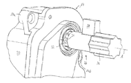
- FIG. 1 shows an embodiment according to the invention of an air flap arrangement designated in general by 10 .
- This comprises a carrier 12 , a rotary drive 14 and an air flap 16 , which is rotatable about an air flap longitudinal axis L.
- the air flap 16 is rotatably received on the carrier 12 .
- the rotary drive 14 is preferably an electric motor rotary drive.
- the air flap 16 has an air flap component 18 , which may have a flat air flap face formation 20 and a longitudinal end-side bearing formation 22 .
- the air flap face formation 20 is used for the actual purpose of the air flap 16 , namely to change an effective through-cross-section of an air through-opening 24 , in which the air flap 16 is usually arranged.
- a counter-stop component 26 which has a counter-stop 28 for contact engagement with a carrier-side stop 38 that cannot be seen in FIG. 1 , can be seen axially between the rotary drive 14 and the air flap 16 (see FIG. 4 ).
- the counter-stop 28 projects upwardly in the radial direction from the remaining counter-stop component 26 .
- the air flap 16 may be coupled by means of the counter-stop component 26 in a torque-transmitting manner to the rotary drive 14 .
- the rotary drive 14 is shown together with the counter-stop component 26 in FIG. 2 .
- Fastening eyes 14 a and 14 b with which the rotary drive 14 , more precisely its housing 30 , can be fastened to one side of the carrier 12 , can be seen.
- the drive shaft 32 of the rotary drive 14 can be configured as a hollow shaft.
- a first connection configuration 34 of the counter-stop component 26 with, for example, a polyhedral peripheral shape can be inserted into the recess of the hollow shaft 32 .
- the inner wall of the hollow shaft 32 is preferably formed correspondingly negatively with respect to the polyhedral peripheral shape of the first connection configuration 34 , so that a torque about the drive shaft axis A can be positively transmitted from the drive shaft 32 to the first connection configuration 34 .
- a second connection configuration 36 which is configured for torque-transmitting coupling to the air flap component 18 , can be configured on the longitudinal end of the counter-stop configuration 26 opposing the first connection configuration 34 .
- the second connection configuration 36 can also have a polyhedral peripheral shape for positive torque transmission from the counter-stop component 26 to the air flap component 18 .
- one or both connection configurations 34 and/or 36 can be configured as a spline shaft profile.
- the counter-stop 28 is formed as a radial extension or protrusion.
- the drive axis A of the drive shaft 32 of the rotary drive 14 and the air flap longitudinal axis L of the air flap 16 or the air flap component 18 are preferably collinear.
- the counter-stop component 26 is shown on its own in FIG. 3 .
- the counter-stop component 26 is preferably made of a plastics material, particularly preferably of a filled plastics material. The latter has a higher tensile strength than the material, preferably the plastics material, of the air flap component 18 .
- the counter-stop component 26 is particularly preferably made of a polyamide “PA66GF30”, in other words of polyamide 6.6 with a glass fibre content of 30%. This material does not only have a higher tensile strength than the material of the air flap component, but moreover has a higher modulus of elasticity than the material of the air flap component 18 in the operating temperature range to be expected.
- the counter-stop component 26 is configured in one piece, for example by injection moulding, for reasons of high strength simultaneously with simple production.
- the air flap component 18 is preferably produced from PPGF30, in other words a polypropylene filled with 30% glass fibres. This material is more economical but does not have the necessary strengths for the forces and loads occurring at the counter-stop 28 with the predetermined stop geometry.
- the air flap component 18 is preferably produced in one piece by an injection moulding method or by another casting method.
- FIG. 4 shows a partial sectional view of the air flap arrangement 10 leaving out the air flap component 18 .
- the counter-stop 28 has a contact engagement on a stop 38 of the carrier 12 . Owing to this contact arrangement, a further rotation of the counter-stop component 26 and, connected therewith, of the air flap component 18 about the air flap rotational axis L in FIG. 4 in the clockwise direction is prevented.
- the contact engagement thus defines a relative end position of the air flap component 18 relative to the carrier 12 and therefore relative to the air through-opening 24 , as the counter-stop component 26 is preferably coupled to the air flap component 18 without play in the rotational direction about the air flap rotational axis L.
- the stop 38 is preferably formed in one piece by injection moulding or by another casting method to the carrier 12 . However, it is not ruled out that the stop 38 is assembled on the carrier 12 as a separate component. The stop 38 is secured to the carrier 12 , i.e. cannot move relative to the carrier 12 except by deformation.
- the counter-stop component 26 passes through a cheek 12 a (see FIG. 1 ) of the carrier 12 , on one side of which the rotary drive 14 can be provided and on the other side of which the air flap component 18 can be provided.
- rotary drives 14 with very strong torque can be used on the air flap arrangement 10 without the stop 38 having to be made thicker or in some other way having a greater space requirement than in conventional solutions with a stop configured in one piece on the air flap component.
- a possible axial fixing of the air flap component 18 on the second connection configuration 36 is shown in FIG. 5 .
- a fixing of this type can preferably be configured as a latching ( 42 , 44 ), for example in that a configuration of a second connection configuration 36 and bearing formation 22 has a latching projection projecting 42 radially toward the respective other configuration and the respective other portion has a corresponding recess 44 .
Landscapes
- Engineering & Computer Science (AREA)
- Mechanical Engineering (AREA)
- Chemical & Material Sciences (AREA)
- Combustion & Propulsion (AREA)
- General Engineering & Computer Science (AREA)
- Physics & Mathematics (AREA)
- Thermal Sciences (AREA)
- Transportation (AREA)
- Air-Conditioning For Vehicles (AREA)
- Air-Flow Control Members (AREA)
Abstract
Description
Claims (18)
Applications Claiming Priority (3)
| Application Number | Priority Date | Filing Date | Title |
|---|---|---|---|
| DE102013206410.1 | 2013-04-11 | ||
| DE102013206410.1A DE102013206410B4 (en) | 2013-04-11 | 2013-04-11 | air flap arrangement with separate stop component |
| DE102013206410 | 2013-04-11 |
Publications (2)
| Publication Number | Publication Date |
|---|---|
| US20140308890A1 US20140308890A1 (en) | 2014-10-16 |
| US10024560B2 true US10024560B2 (en) | 2018-07-17 |
Family
ID=51618333
Family Applications (1)
| Application Number | Title | Priority Date | Filing Date |
|---|---|---|---|
| US14/249,900 Active 2037-05-18 US10024560B2 (en) | 2013-04-11 | 2014-04-10 | Air flap arrangement with a separate stop component |
Country Status (2)
| Country | Link |
|---|---|
| US (1) | US10024560B2 (en) |
| DE (1) | DE102013206410B4 (en) |
Cited By (5)
| Publication number | Priority date | Publication date | Assignee | Title |
|---|---|---|---|---|
| US10166858B2 (en) * | 2016-04-19 | 2019-01-01 | Batz, S.Coop. | Shutter device for a front grille of a vehicle |
| US10421352B2 (en) * | 2017-12-13 | 2019-09-24 | Röchling Automotive SE & Co. KG | Air flap apparatus having a shifting drum having control grooves on the enveloping surface |
| US11364791B2 (en) * | 2019-04-16 | 2022-06-21 | Flex-N-Gate France | Ventilation device for a vehicle, associated vehicle |
| US20230331079A1 (en) * | 2020-09-29 | 2023-10-19 | Hanon Systems | Active air flap |
| US20230408138A1 (en) * | 2020-11-05 | 2023-12-21 | Valeo Climate Control Corp. | Heating ventilation and air conditioning (hvac) unit |
Families Citing this family (14)
| Publication number | Priority date | Publication date | Assignee | Title |
|---|---|---|---|---|
| DE102011002606B4 (en) * | 2011-01-13 | 2022-12-15 | Ford Global Technologies, Llc | Ventilation control device for a heating and/or air conditioning system of a vehicle |
| KR101532976B1 (en) * | 2014-09-01 | 2015-07-01 | 현대모비스 주식회사 | Air flap device for vehicle |
| DE102014114639B4 (en) | 2014-10-09 | 2024-10-02 | Dr. Ing. H.C. F. Porsche Aktiengesellschaft | Air control device for controlling air flow into a vehicle |
| DE102016222918A1 (en) * | 2016-11-21 | 2018-05-24 | Mahle International Gmbh | Air controller |
| US10809021B2 (en) * | 2016-12-08 | 2020-10-20 | Hamilton Sunstrand Corporation | Heat exchanger with sliding aperture valve |
| FR3061875B1 (en) * | 2017-01-17 | 2024-01-05 | Valeo Systemes Thermiques | FLAP FOR A MOTOR VEHICLE SHUTTING DEVICE AND METHOD FOR MANUFACTURING SUCH A FLAP |
| US10093173B1 (en) * | 2017-07-26 | 2018-10-09 | Srg Global Inc. | Active grille shutter system with louver compensation feature |
| FR3070633B1 (en) * | 2017-09-01 | 2020-07-17 | Valeo Systemes Thermiques | SHUTTER SHUTTER FOR AIR FLOW REGULATION DEVICE FOR FRONT PANEL MODULE FOR MOTOR VEHICLE |
| JP6922654B2 (en) * | 2017-10-27 | 2021-08-18 | 豊田合成株式会社 | Vehicle grill shutter device |
| KR102512384B1 (en) * | 2018-02-27 | 2023-03-22 | 한온시스템 주식회사 | Air conditioner for vehicle |
| CN208085650U (en) * | 2018-04-23 | 2018-11-13 | 延锋彼欧汽车外饰系统有限公司 | A kind of active air-inlet grille with blade protection structure |
| EP3643551B1 (en) | 2018-10-24 | 2021-06-23 | Batz, S.Coop. | Shutter device for a front grille of a vehicle |
| DE102022105548A1 (en) * | 2022-03-09 | 2023-09-14 | Dr. Ing. H.C. F. Porsche Aktiengesellschaft | Air guiding device of a motor vehicle body of a motor vehicle |
| DE102022130009A1 (en) | 2022-11-14 | 2024-05-16 | Dr. Ing. H.C. F. Porsche Aktiengesellschaft | Slat device for a motor vehicle |
Citations (7)
| Publication number | Priority date | Publication date | Assignee | Title |
|---|---|---|---|---|
| EP0692397A1 (en) | 1994-07-15 | 1996-01-17 | Behr GmbH & Co. | Air damper for a heating or air conditioning device |
| FR2764666A1 (en) | 1997-06-17 | 1998-12-18 | Valeo Climatisation | Air conditioning/air ventilating equipment in motor vehicles |
| DE10018268A1 (en) | 2000-04-13 | 2001-10-18 | Behr Gmbh & Co | Airflow control element of heating or conditioning system of motor vehicle has one edge of louver-type airflow control element irregularly constructed and may be serrated or notched |
| DE102004036667A1 (en) | 2004-07-28 | 2006-03-23 | Behr Gmbh & Co. Kg | Air flap assembly |
| EP2368731A1 (en) | 2010-03-18 | 2011-09-28 | Behr France Rouffach SAS | Device for actuating two pivotable flaps |
| DE102011082519A1 (en) | 2011-09-12 | 2013-03-14 | Behr Gmbh & Co. Kg | Air damper for air-conditioner used in motor vehicle, has damping elements that are integrated to flap element and/or rotating unit and/or housing, in order to attenuate operating noise |
| US20130149955A1 (en) * | 2011-12-13 | 2013-06-13 | Ronald E. Jackson | Barometric relief air zone damper |
-
2013
- 2013-04-11 DE DE102013206410.1A patent/DE102013206410B4/en active Active
-
2014
- 2014-04-10 US US14/249,900 patent/US10024560B2/en active Active
Patent Citations (7)
| Publication number | Priority date | Publication date | Assignee | Title |
|---|---|---|---|---|
| EP0692397A1 (en) | 1994-07-15 | 1996-01-17 | Behr GmbH & Co. | Air damper for a heating or air conditioning device |
| FR2764666A1 (en) | 1997-06-17 | 1998-12-18 | Valeo Climatisation | Air conditioning/air ventilating equipment in motor vehicles |
| DE10018268A1 (en) | 2000-04-13 | 2001-10-18 | Behr Gmbh & Co | Airflow control element of heating or conditioning system of motor vehicle has one edge of louver-type airflow control element irregularly constructed and may be serrated or notched |
| DE102004036667A1 (en) | 2004-07-28 | 2006-03-23 | Behr Gmbh & Co. Kg | Air flap assembly |
| EP2368731A1 (en) | 2010-03-18 | 2011-09-28 | Behr France Rouffach SAS | Device for actuating two pivotable flaps |
| DE102011082519A1 (en) | 2011-09-12 | 2013-03-14 | Behr Gmbh & Co. Kg | Air damper for air-conditioner used in motor vehicle, has damping elements that are integrated to flap element and/or rotating unit and/or housing, in order to attenuate operating noise |
| US20130149955A1 (en) * | 2011-12-13 | 2013-06-13 | Ronald E. Jackson | Barometric relief air zone damper |
Non-Patent Citations (1)
| Title |
|---|
| Search Report dated Jan. 29, 2014, issued in corresponding German application 10 2013 206 410.1, 5 pages. |
Cited By (6)
| Publication number | Priority date | Publication date | Assignee | Title |
|---|---|---|---|---|
| US10166858B2 (en) * | 2016-04-19 | 2019-01-01 | Batz, S.Coop. | Shutter device for a front grille of a vehicle |
| US10421352B2 (en) * | 2017-12-13 | 2019-09-24 | Röchling Automotive SE & Co. KG | Air flap apparatus having a shifting drum having control grooves on the enveloping surface |
| US11364791B2 (en) * | 2019-04-16 | 2022-06-21 | Flex-N-Gate France | Ventilation device for a vehicle, associated vehicle |
| US20230331079A1 (en) * | 2020-09-29 | 2023-10-19 | Hanon Systems | Active air flap |
| US12606009B2 (en) * | 2020-09-29 | 2026-04-21 | Hanon Systems | Active air flap |
| US20230408138A1 (en) * | 2020-11-05 | 2023-12-21 | Valeo Climate Control Corp. | Heating ventilation and air conditioning (hvac) unit |
Also Published As
| Publication number | Publication date |
|---|---|
| US20140308890A1 (en) | 2014-10-16 |
| DE102013206410B4 (en) | 2024-10-17 |
| DE102013206410A1 (en) | 2014-10-16 |
Similar Documents
| Publication | Publication Date | Title |
|---|---|---|
| US10024560B2 (en) | Air flap arrangement with a separate stop component | |
| US9446660B2 (en) | Vehicle grill shutter, vehicle flap member, and actuator | |
| JP5364164B2 (en) | Brake disc with brake disc pot | |
| KR100824660B1 (en) | Cooling device | |
| CN103906670B (en) | Electric type power steering device | |
| US20160047456A1 (en) | Belt Pulley and Gear Nut with Such a Belt Pulley | |
| WO2010066540A1 (en) | Impeller for a fan | |
| CN101091066A (en) | Shaft-hub-connection with fixing system | |
| CN111086384A (en) | Shutter device for the front grill of a vehicle | |
| US9562535B2 (en) | Cross-flow fan, electronic device including cross-flow fan, and impeller used for cross-flow fan | |
| JP2018530716A (en) | Auxiliary drive belt tensioner | |
| BRPI0612759A2 (en) | pre-tensioned shaft / hub connection that has a perfect cone shape | |
| CN102084147A (en) | Device for torque transmission, especially for an air-conditionning compressor | |
| MX2010011559A (en) | Structural unit. | |
| BR102012007804A2 (en) | ENGINE COOLING DRIVE SYSTEM FOR AUTOMOTIVE VEHICLES | |
| CN104078138B (en) | Wire protection drag chain and air conditioner with same | |
| EP2276330A2 (en) | Housing wall for fixing a device to a machine | |
| KR101469944B1 (en) | Compressor having airgap regulating part | |
| CN105715772A (en) | Position Control Actuator As Well As Method For Producing Position Control Actuator And Mechanism In Motor Vehicle For Actuator | |
| KR102012371B1 (en) | Power interrupt device of clutchless compressor | |
| KR101377367B1 (en) | Coilless clutch device used in air conditioner compressor for vehicle | |
| KR200440163Y1 (en) | Cooling Fan for Reducer | |
| DE4441039C1 (en) | Fluid friction coupling with cooling air fan | |
| JP6180190B2 (en) | Blower fan | |
| JP7776484B2 (en) | Angular position holding device |
Legal Events
| Date | Code | Title | Description |
|---|---|---|---|
| AS | Assignment |
Owner name: ROCHLING AUTOMOTIVE SE & CO. KG, GERMANY Free format text: ASSIGNMENT OF ASSIGNORS INTEREST;ASSIGNOR:SCHNEIDER, JURGEN;REEL/FRAME:032649/0060 Effective date: 20140307 |
|
| AS | Assignment |
Owner name: ROECHLING AUTOMOTIVE SE & CO. KG, GERMANY Free format text: CORRECTIVE ASSIGNMENT TO CORRECT THE NAME OF CONVEYING PARTY AND NAME OF RECEIVING PARTY. PREVIOUSLY RECORDED AT REEL: 032649 FRAME: 0060. ASSIGNOR(S) HEREBY CONFIRMS THE ASSIGNMENT;ASSIGNOR:SCHNEIDER, JUERGEN;REEL/FRAME:042318/0132 Effective date: 20140310 |
|
| STCF | Information on status: patent grant |
Free format text: PATENTED CASE |
|
| MAFP | Maintenance fee payment |
Free format text: PAYMENT OF MAINTENANCE FEE, 4TH YEAR, LARGE ENTITY (ORIGINAL EVENT CODE: M1551); ENTITY STATUS OF PATENT OWNER: LARGE ENTITY Year of fee payment: 4 |
|
| AS | Assignment |
Owner name: ROECHLING AUTOMOTIVE SE, GERMANY Free format text: ASSIGNMENT OF ASSIGNORS INTEREST;ASSIGNOR:ROECHLING AUTOMOTIVE SE & CO. KG;REEL/FRAME:064931/0671 Effective date: 20230726 |
|
| MAFP | Maintenance fee payment |
Free format text: PAYMENT OF MAINTENANCE FEE, 8TH YEAR, LARGE ENTITY (ORIGINAL EVENT CODE: M1552); ENTITY STATUS OF PATENT OWNER: LARGE ENTITY Year of fee payment: 8 |