US10024422B2 - Method for controlling lock-up clutch of automatic transmission - Google Patents
Method for controlling lock-up clutch of automatic transmission Download PDFInfo
- Publication number
- US10024422B2 US10024422B2 US15/257,263 US201615257263A US10024422B2 US 10024422 B2 US10024422 B2 US 10024422B2 US 201615257263 A US201615257263 A US 201615257263A US 10024422 B2 US10024422 B2 US 10024422B2
- Authority
- US
- United States
- Prior art keywords
- clutch
- solenoid valve
- lock
- current
- amount
- Prior art date
- Legal status (The legal status is an assumption and is not a legal conclusion. Google has not performed a legal analysis and makes no representation as to the accuracy of the status listed.)
- Active, expires
Links
- 238000000034 method Methods 0.000 title claims abstract description 15
- 230000005540 biological transmission Effects 0.000 title claims abstract description 13
- 230000002401 inhibitory effect Effects 0.000 description 6
- 239000000446 fuel Substances 0.000 description 3
- 238000007792 addition Methods 0.000 description 1
- 238000005516 engineering process Methods 0.000 description 1
- 238000012986 modification Methods 0.000 description 1
- 230000004048 modification Effects 0.000 description 1
- 238000006467 substitution reaction Methods 0.000 description 1
- 239000013589 supplement Substances 0.000 description 1
Images


Classifications
-
- F—MECHANICAL ENGINEERING; LIGHTING; HEATING; WEAPONS; BLASTING
- F16—ENGINEERING ELEMENTS AND UNITS; GENERAL MEASURES FOR PRODUCING AND MAINTAINING EFFECTIVE FUNCTIONING OF MACHINES OR INSTALLATIONS; THERMAL INSULATION IN GENERAL
- F16H—GEARING
- F16H61/00—Control functions within control units of change-speed- or reversing-gearings for conveying rotary motion ; Control of exclusively fluid gearing, friction gearing, gearings with endless flexible members or other particular types of gearing
- F16H61/02—Control functions within control units of change-speed- or reversing-gearings for conveying rotary motion ; Control of exclusively fluid gearing, friction gearing, gearings with endless flexible members or other particular types of gearing characterised by the signals used
- F16H61/0202—Control functions within control units of change-speed- or reversing-gearings for conveying rotary motion ; Control of exclusively fluid gearing, friction gearing, gearings with endless flexible members or other particular types of gearing characterised by the signals used the signals being electric
- F16H61/0204—Control functions within control units of change-speed- or reversing-gearings for conveying rotary motion ; Control of exclusively fluid gearing, friction gearing, gearings with endless flexible members or other particular types of gearing characterised by the signals used the signals being electric for gearshift control, e.g. control functions for performing shifting or generation of shift signal
- F16H61/0206—Layout of electro-hydraulic control circuits, e.g. arrangement of valves
-
- F—MECHANICAL ENGINEERING; LIGHTING; HEATING; WEAPONS; BLASTING
- F16—ENGINEERING ELEMENTS AND UNITS; GENERAL MEASURES FOR PRODUCING AND MAINTAINING EFFECTIVE FUNCTIONING OF MACHINES OR INSTALLATIONS; THERMAL INSULATION IN GENERAL
- F16H—GEARING
- F16H61/00—Control functions within control units of change-speed- or reversing-gearings for conveying rotary motion ; Control of exclusively fluid gearing, friction gearing, gearings with endless flexible members or other particular types of gearing
- F16H61/14—Control of torque converter lock-up clutches
- F16H61/143—Control of torque converter lock-up clutches using electric control means
-
- F—MECHANICAL ENGINEERING; LIGHTING; HEATING; WEAPONS; BLASTING
- F16—ENGINEERING ELEMENTS AND UNITS; GENERAL MEASURES FOR PRODUCING AND MAINTAINING EFFECTIVE FUNCTIONING OF MACHINES OR INSTALLATIONS; THERMAL INSULATION IN GENERAL
- F16H—GEARING
- F16H61/00—Control functions within control units of change-speed- or reversing-gearings for conveying rotary motion ; Control of exclusively fluid gearing, friction gearing, gearings with endless flexible members or other particular types of gearing
- F16H61/04—Smoothing ratio shift
- F16H61/06—Smoothing ratio shift by controlling rate of change of fluid pressure
- F16H61/061—Smoothing ratio shift by controlling rate of change of fluid pressure using electric control means
-
- F—MECHANICAL ENGINEERING; LIGHTING; HEATING; WEAPONS; BLASTING
- F16—ENGINEERING ELEMENTS AND UNITS; GENERAL MEASURES FOR PRODUCING AND MAINTAINING EFFECTIVE FUNCTIONING OF MACHINES OR INSTALLATIONS; THERMAL INSULATION IN GENERAL
- F16H—GEARING
- F16H63/00—Control outputs from the control unit to change-speed- or reversing-gearings for conveying rotary motion or to other devices than the final output mechanism
- F16H63/40—Control outputs from the control unit to change-speed- or reversing-gearings for conveying rotary motion or to other devices than the final output mechanism comprising signals other than signals for actuating the final output mechanisms
- F16H63/46—Signals to a clutch outside the gearbox
-
- F—MECHANICAL ENGINEERING; LIGHTING; HEATING; WEAPONS; BLASTING
- F16—ENGINEERING ELEMENTS AND UNITS; GENERAL MEASURES FOR PRODUCING AND MAINTAINING EFFECTIVE FUNCTIONING OF MACHINES OR INSTALLATIONS; THERMAL INSULATION IN GENERAL
- F16H—GEARING
- F16H61/00—Control functions within control units of change-speed- or reversing-gearings for conveying rotary motion ; Control of exclusively fluid gearing, friction gearing, gearings with endless flexible members or other particular types of gearing
- F16H2061/0075—Control functions within control units of change-speed- or reversing-gearings for conveying rotary motion ; Control of exclusively fluid gearing, friction gearing, gearings with endless flexible members or other particular types of gearing characterised by a particular control method
- F16H2061/0096—Control functions within control units of change-speed- or reversing-gearings for conveying rotary motion ; Control of exclusively fluid gearing, friction gearing, gearings with endless flexible members or other particular types of gearing characterised by a particular control method using a parameter map
-
- F—MECHANICAL ENGINEERING; LIGHTING; HEATING; WEAPONS; BLASTING
- F16—ENGINEERING ELEMENTS AND UNITS; GENERAL MEASURES FOR PRODUCING AND MAINTAINING EFFECTIVE FUNCTIONING OF MACHINES OR INSTALLATIONS; THERMAL INSULATION IN GENERAL
- F16H—GEARING
- F16H61/00—Control functions within control units of change-speed- or reversing-gearings for conveying rotary motion ; Control of exclusively fluid gearing, friction gearing, gearings with endless flexible members or other particular types of gearing
- F16H61/02—Control functions within control units of change-speed- or reversing-gearings for conveying rotary motion ; Control of exclusively fluid gearing, friction gearing, gearings with endless flexible members or other particular types of gearing characterised by the signals used
- F16H61/0202—Control functions within control units of change-speed- or reversing-gearings for conveying rotary motion ; Control of exclusively fluid gearing, friction gearing, gearings with endless flexible members or other particular types of gearing characterised by the signals used the signals being electric
- F16H61/0204—Control functions within control units of change-speed- or reversing-gearings for conveying rotary motion ; Control of exclusively fluid gearing, friction gearing, gearings with endless flexible members or other particular types of gearing characterised by the signals used the signals being electric for gearshift control, e.g. control functions for performing shifting or generation of shift signal
- F16H61/0206—Layout of electro-hydraulic control circuits, e.g. arrangement of valves
- F16H2061/0209—Layout of electro-hydraulic control circuits, e.g. arrangement of valves with independent solenoid valves modulating the pressure individually for each clutch or brake
-
- F—MECHANICAL ENGINEERING; LIGHTING; HEATING; WEAPONS; BLASTING
- F16—ENGINEERING ELEMENTS AND UNITS; GENERAL MEASURES FOR PRODUCING AND MAINTAINING EFFECTIVE FUNCTIONING OF MACHINES OR INSTALLATIONS; THERMAL INSULATION IN GENERAL
- F16H—GEARING
- F16H61/00—Control functions within control units of change-speed- or reversing-gearings for conveying rotary motion ; Control of exclusively fluid gearing, friction gearing, gearings with endless flexible members or other particular types of gearing
- F16H61/14—Control of torque converter lock-up clutches
- F16H61/143—Control of torque converter lock-up clutches using electric control means
- F16H2061/146—Control of torque converter lock-up clutches using electric control means for smoothing gear shift shock
-
- Y10T477/635—
-
- Y10T477/641—
-
- Y10T477/735—
Definitions
- the present disclosure relates generally to a method of controlling a lock-up clutch of an automatic transmission.
- a lock-up clutch system is used to supplement this weakness and to improve the efficiency.
- a typical example of the lock-up clutch is a 3-way separate chamber multi-plate clutch.
- the gear change operation of the automatic transmission is performed by selectively engaging or releasing friction elements, the friction elements including a plurality of clutches and a brake.
- a desired gear change may be achieved by simultaneously releasing the second clutch and engaging the third clutch, while maintaining the engaged first clutch.
- the lock-up clutch absorbs gear change impact transferred to the vehicle by performing precise slip control and maintaining the pressure at a low level.
- an amount of oil in a pump is consumed equal to the volume of the third clutch, during an initial fill time period when the third clutch is operated and then the amount of oil in the lock-up clutch is reduced momentarily.
- pressure reduction occurs in the lock-up clutch, which causes impact to the vehicle.
- the present disclosure proposes a method of controlling a lock-up clutch of an automatic transmission, in which control operational stability of the lock-up cultch is improved even when an amount of oil in a pump is consumed due to a gear change operation.
- the method for controlling a lock-up clutch of an automatic transmission includes: a detecting step of detecting, by a controller, a current signal applied to a solenoid valve of an engaging element when a gear change operation begins, the solenoid valve of the engaging element being used to form a gear stage, and a first increasing control step of controlling, by the controller, an amount of current that is applied to a solenoid valve of a lock-up clutch during an initial fill time period when it is determined that the current signal is applied to the solenoid valve of the engaging element, wherein the controller controls the amount of current by increasing the amount of current to a predetermined level for a predetermined period of time.
- the increased amount of current applied to the solenoid valve of the lock-up clutch and the predetermined period of time in which the amount of current is increased may be determined by a first map data that forms a relationship between an oil temperature, a target gear stage, and an engine rpm.
- the amount of current applied to the solenoid valve of the lock-up clutch may be controlled by increasing the amount of current after the current signal is applied to the solenoid valve of the engaging element.
- the method may further include, after the first increasing control step: a second increasing control step of controlling, by the controller, an amount of current that is applied to the solenoid valve of the lock-up clutch when it is determined that the gear change operation is ended by applying a current signal that is equal to or greater than a preset value to the solenoid valve of the engaging element, wherein the controller may control the amount of current by increasing the amount of current to a predetermined level for a predetermined period of time.
- the increased amount of current applied to the solenoid valve of the lock-up clutch and the predetermined period of time in which the amount of current is increased may be determined by a second map data that forms a relationship between an oil temperature, a target gear stage, and an engine rpm.
- the controller may control the amount of current of the solenoid valve of the lock-up clutch by increasing the amount of current, and simultaneously applies the current signal, which is equal to or greater than the preset value, to the solenoid valve of the engaging element.
- the present disclosure improves gear change control stability of a lock-up cultch by inhibiting or preventing pressure reduction in the lock-up clutch by properly compensating for the reduced amount of oil in the lock-up clutch, which is caused by the amount of oil consumed by an engaging element during an initial fill time period when a gear change operation starts.
- the present disclosure also properly compensates for the reduction in the amount of oil in the lock-up clutch, which is caused by the amount of oil consumed by the engaging element at the end of the gear change operation, thereby inhibiting or preventing pressure reduction in the lock-up clutch and further improving gear change control stability.
- FIG. 1 is a schematic view illustrating an oil pressure control configuration of an automatic transmission which is applicable to the present disclosure
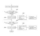
- FIG. 2 is a flow chart explaining a control flow of a lock-up clutch according to the present disclosure.
- FIG. 3 is a graph showing an oil pressure behavior of the lock-up clutch by comparing results obtained when a control of the lock-up clutch according to the present disclosure is applied or not.
- a method of controlling a lock-up clutch of an automatic transmission may be configured to include a detecting step and a first increasing control step.
- a controller 1 may detect a current signal that is applied to a solenoid valve SV 1 , SV 2 , SV 3 of an engaging element when a gear change operation starts, the solenoid valve of the engaging element being used to form a gear stage.
- the engaging element may be a clutch or a brake constituting friction elements of the automatic transmission, in which the clutch or the brake performs an engaging operation to form a target gear stage during a gear change operation.
- a release element shown in FIG. 3 may be a clutch or a brake that performs a release operation to form a target gear stage during a gear change operation.
- the engaging element and the release element may be changed according to the requirement of the friction elements for performing a gear change operation to realize a target gear stage.
- an automatic transmission that is provided with three clutches as shown in FIG. 1 is illustrated and described.
- the third clutch among the three clutches is illustrated as the engaging element, and second clutch is illustrated as the release element which will be described later.
- the controller 1 may control the amount of current that is applied to a solenoid valve of a lock-up clutch DCCSV during an initial fill time period of the engaging element.
- the controller may control the amount of current by increasing the amount of current to a predetermined level for a predetermined lengthy period of time.
- the second clutch (release element) is released to perform the gear change operation for realizing a target gear stage and the third clutch (engaging element) is simultaneously engaged; then, the current signal is input to a solenoid valve SV 3 of the third clutch to control the oil pressure of the third clutch, and, an amount of current, which is equal to or greater than a predetermined amount of current, is simultaneously applied to the solenoid valve of the lock-up clutch to control the oil pressure of the lock-up clutch.
- the increased amount of current applied to the solenoid valve of the lock-up clutch and the predetermined lengthy period of time in which the amount of current is increased may be determined by first map data that forms a relationship between an oil temperature, a target gear stage and/or a present gear stage, and an engine rpm.
- the first map data which compensates for an oil pressure reduction of the lock-up clutch in certain engine conditions, forms a relationship between a minimum amount of increased current and a lengthy period of time in which the amount of current is increased.
- the pressure of the lock-up clutch may be stably controlled.
- the controller 1 may control the amount of current that is applied to the solenoid valve of the lock-up clutch DCCSV by increasing the amount of current to a predetermined level after the current signal is applied to the solenoid valve SV 3 of the engaging element.
- the current signal is applied to the solenoid valve SV 3 of the engaging element, and then, with a predetermined delay time, the controller controls the current of the solenoid valve of the lock-up clutch DCCSV. Therefore, the amount of oil in the lock-up clutch is increased before oil is consumed by the third clutch during the initial fill time period. A risk, in which the pressure of the lock-up clutch is increased, is inhibited or prevented.
- the controller 1 may further include a second increasing control step which controls the amount of current applied to the solenoid valve of the lock-up clutch by increasing the amount of current to a predetermined level for a predetermined lengthy period of time.
- the controller 1 when the gear change operation starts, in order to engage the third clutch (engaging element) by increasing its pressure up to a line pressure, the controller 1 applies the current signal, which is equal to or greater than the preset value, to the solenoid valve SV 3 of the third clutch to control the oil pressure of the third clutch. Then, the controller 1 instantaneously applies the current, which is equal to or greater than the preset value, to the solenoid valve of the lock-up clutch in order to control the oil pressure of the lock-up clutch.
- the controller 1 controls the amount of oil in the lock-up clutch by simultaneously increasing the amount of current applied to the solenoid valve of the lock-up clutch. Then, the reduction in the amount of oil in the lock-up clutch due to the oil consumption of the third clutch at the end period of the gear change operation is compensated. Therefore, gear change control stability is improved by inhibiting or preventing the pressure reduction of the lock-up clutch.
- the increased amount of current applied to the solenoid valve of the lock-up clutch DCCSV and the predetermined lengthy period of time may be determined by second map data which forms a relationship between an oil temperature, a target gear stage, and an engine rpm.
- the second map data which can compensate the oil pressure reduction of the lock-up clutch in certain engine condition, forms a relationship between minimum amount of increased current and lengthy period of time in which the amount of current is increased.
- the pressure of the lock-up clutch may be stably controlled.
- the controller 1 controls the amount of current applied to the solenoid valve of the lock-up clutch by increasing the amount of current, simultaneously with application of the current signal, which is equal to or greater than the preset value, to the solenoid valve of the engaging element.
- a step S 10 detects whether an initial current signal is applied to the solenoid valve SV 3 of the engaging element (e.g., third clutch).
- the engaging element e.g., third clutch
- a step S 20 determines by use of the first map data an amount of increased current and a lengthy period of time in which the amount of current is increased, both of which are used to control the current of the lock-up clutch.
- a step S 30 controls the current of the solenoid valve of the lock-up clutch DCCSV by increasing the amount of current to the determined increased amount of current for the determined lengthy period of time in which the amount of current is increased. Hence, a pressure reduction of the lock-up clutch during an initial fill time period of the engaging element is inhibited or prevented.
- S 40 determines whether the gear change operation is ended by detecting a current signal, which is equal to or greater than a preset value, in the solenoid valve SV 3 of the engaging element.
- a step S 50 determines, by using a second map data, an amount of increased current and a lengthy period of time of the increased current, which are both used to control the current of the lock-up clutch.
- a step S 60 controls the current of the solenoid valve of the lock-up clutch DCCSV by increasing the amount of current to the determined increased amount of current for the determined lengthy period of time in which the amount of current is increased.
- the reduction in the amount of oil in the lock-up clutch which is caused by the oil consumption of the third clutch during the initial fill time period, is properly compensated, and therefore, gear change control stability is improved by inhibiting or preventing the pressure reduction of the lock-up clutch.
- the reduction in the amount of oil in the lock-up clutch which is caused by the oil consumption occurring when operating the third clutch at the end period of the gear change operation of the third clutch, is inhibited or prevented, and therefore, gear change control stability is improved by inhibiting or preventing the pressure reduction of the lock-up clutch.
Landscapes
- Engineering & Computer Science (AREA)
- General Engineering & Computer Science (AREA)
- Mechanical Engineering (AREA)
- Physics & Mathematics (AREA)
- Fluid Mechanics (AREA)
- Control Of Transmission Device (AREA)
- Control Of Fluid Gearings (AREA)
Abstract
The present disclosure relates to a method for controlling a lock-up clutch of an automatic transmission. The method includes: a detecting step of detecting, by a controller, a current signal applied to a solenoid valve of an engaging element when a gear change operation begins; and a first increasing control step of controlling, by the controller, an amount of current that is applied to a solenoid valve of a lock-up clutch during an initial fill time period when it is determined that the current signal is applied to the solenoid valve of the engaging element. In particular, the solenoid valve of the engaging element is used to form a gear stage, and the controller increases the amount of current to a predetermined level for a predetermined period of time.
Description
The present application claims priority to and the benefit of Korean Patent Application No. 10-2016-0048013, filed Apr. 20, 2016, which is incorporated herein by reference in its entirety.
The present disclosure relates generally to a method of controlling a lock-up clutch of an automatic transmission.
The statements in this section merely provide background information related to the present disclosure and may not constitute prior art.
High global oil prices, fuel efficiency due to CO2 regulations, and eco-environment concerns are important considerations in vehicle development. In order to achieve these goals, Automobile manufacturers are devoting their efforts into developing technologies to improve fuel efficiency.
It is important to reduce power loss of an automatic transmission to improve the fuel efficiency of a vehicle. In particular, it is important to reduce power loss of a torque converter.
Power loss of the torque converter always occurs since the torque converter of the automatic transmission transfers the power using oil, and a lock-up clutch system is used to supplement this weakness and to improve the efficiency. Hence, it has been developed in direction to expand operating area of the lock-up clutch to improve efficiency of the entire driving of vehicle. A typical example of the lock-up clutch is a 3-way separate chamber multi-plate clutch.
However, since the operating area of the lock-up clutch is expanded, a precise slip control is desired. In particular, we have discovered that an excellent gear change feel of the vehicle is desired.
Meanwhile, the gear change operation of the automatic transmission is performed by selectively engaging or releasing friction elements, the friction elements including a plurality of clutches and a brake.
For example, when three clutches are provided as friction factors, a desired gear change may be achieved by simultaneously releasing the second clutch and engaging the third clutch, while maintaining the engaged first clutch. Herein, the lock-up clutch absorbs gear change impact transferred to the vehicle by performing precise slip control and maintaining the pressure at a low level.
However, we have discovered that in the conventional art, when the control pressure of the lock-up clutch is only controlled to be maintained at a low level, some problems occur as described below.
First, an amount of oil in a pump is consumed equal to the volume of the third clutch, during an initial fill time period when the third clutch is operated and then the amount of oil in the lock-up clutch is reduced momentarily. Thus, pressure reduction occurs in the lock-up clutch, which causes impact to the vehicle.
Second, when the gear change operation is ended according to the engagement and release of the clutches, pressure of the third clutch is raised up to a line pressure. In this case, like the first problem, the amount of oil in the lock-up clutch is reduced equal to the amount of oil flowing into the third clutch. Thus, the pressure of the lock-up clutch is reduced, which also causes impact to the vehicle.
The foregoing is intended merely to aid in the understanding of the background of the present disclosure, and is not intended to mean that the present disclosure falls within the purview of the related art that is already known to those skilled in the art.
The present disclosure proposes a method of controlling a lock-up clutch of an automatic transmission, in which control operational stability of the lock-up cultch is improved even when an amount of oil in a pump is consumed due to a gear change operation.
In one form, the method for controlling a lock-up clutch of an automatic transmission includes: a detecting step of detecting, by a controller, a current signal applied to a solenoid valve of an engaging element when a gear change operation begins, the solenoid valve of the engaging element being used to form a gear stage, and a first increasing control step of controlling, by the controller, an amount of current that is applied to a solenoid valve of a lock-up clutch during an initial fill time period when it is determined that the current signal is applied to the solenoid valve of the engaging element, wherein the controller controls the amount of current by increasing the amount of current to a predetermined level for a predetermined period of time.
In the first increasing control step, the increased amount of current applied to the solenoid valve of the lock-up clutch and the predetermined period of time in which the amount of current is increased may be determined by a first map data that forms a relationship between an oil temperature, a target gear stage, and an engine rpm.
In the first increasing control step, the amount of current applied to the solenoid valve of the lock-up clutch may be controlled by increasing the amount of current after the current signal is applied to the solenoid valve of the engaging element.
The method may further include, after the first increasing control step: a second increasing control step of controlling, by the controller, an amount of current that is applied to the solenoid valve of the lock-up clutch when it is determined that the gear change operation is ended by applying a current signal that is equal to or greater than a preset value to the solenoid valve of the engaging element, wherein the controller may control the amount of current by increasing the amount of current to a predetermined level for a predetermined period of time.
In the second increasing control step, the increased amount of current applied to the solenoid valve of the lock-up clutch and the predetermined period of time in which the amount of current is increased may be determined by a second map data that forms a relationship between an oil temperature, a target gear stage, and an engine rpm.
In the second increasing control step, the controller may control the amount of current of the solenoid valve of the lock-up clutch by increasing the amount of current, and simultaneously applies the current signal, which is equal to or greater than the preset value, to the solenoid valve of the engaging element.
Accordingly, the present disclosure improves gear change control stability of a lock-up cultch by inhibiting or preventing pressure reduction in the lock-up clutch by properly compensating for the reduced amount of oil in the lock-up clutch, which is caused by the amount of oil consumed by an engaging element during an initial fill time period when a gear change operation starts. The present disclosure also properly compensates for the reduction in the amount of oil in the lock-up clutch, which is caused by the amount of oil consumed by the engaging element at the end of the gear change operation, thereby inhibiting or preventing pressure reduction in the lock-up clutch and further improving gear change control stability.
Further areas of applicability will become apparent from the description provided herein. It should be understood that the description and specific examples are intended for purposes of illustration only and are not intended to limit the scope of the present disclosure.
In order that the disclosure may be well understood, there will now be described various forms thereof, given by way of example, reference being made to the accompanying drawings, in which:
The drawings described herein are for illustration purposes only and are not intended to limit the scope of the present disclosure in any way.
The following description is merely exemplary in nature and is not intended to limit the present disclosure, application, or uses. It should be understood that throughout the drawings, corresponding reference numerals indicate like or corresponding parts and features.
A method of controlling a lock-up clutch of an automatic transmission may be configured to include a detecting step and a first increasing control step.
The present disclosure will be described in detail with reference to FIGS. 2 and 3 . First, in the detecting step, a controller 1 may detect a current signal that is applied to a solenoid valve SV1, SV2, SV3 of an engaging element when a gear change operation starts, the solenoid valve of the engaging element being used to form a gear stage.
Here, the engaging element may be a clutch or a brake constituting friction elements of the automatic transmission, in which the clutch or the brake performs an engaging operation to form a target gear stage during a gear change operation. A release element shown in FIG. 3 may be a clutch or a brake that performs a release operation to form a target gear stage during a gear change operation. The engaging element and the release element may be changed according to the requirement of the friction elements for performing a gear change operation to realize a target gear stage.
In one form of present disclosure, an automatic transmission that is provided with three clutches as shown in FIG. 1 is illustrated and described. For convenience of the description, the third clutch among the three clutches is illustrated as the engaging element, and second clutch is illustrated as the release element which will be described later.
In addition, in the first increasing control step shown in FIGS. 2 and 3 , when the current signal is applied to the solenoid valve SV3 of the engaging element (i.e., the third clutch), the controller 1 may control the amount of current that is applied to a solenoid valve of a lock-up clutch DCCSV during an initial fill time period of the engaging element. Here, the controller may control the amount of current by increasing the amount of current to a predetermined level for a predetermined lengthy period of time.
In other words, when a gear change operation starts, the second clutch (release element) is released to perform the gear change operation for realizing a target gear stage and the third clutch (engaging element) is simultaneously engaged; then, the current signal is input to a solenoid valve SV3 of the third clutch to control the oil pressure of the third clutch, and, an amount of current, which is equal to or greater than a predetermined amount of current, is simultaneously applied to the solenoid valve of the lock-up clutch to control the oil pressure of the lock-up clutch.
Thus, when the gear change operation starts, the amount of current of the solenoid valve of the lock-up clutch DCCSV is controlled by momentarily increasing the amount of current when the third clutch is engaged. Therefore, a reduction in the amount of oil in the lock-up clutch, which is caused by the oil consumption of the third clutch during the initial fill time period, is compensated. Thus, gear change control stability is realized by inhibiting or preventing pressure reduction in the lock-up clutch.
Referring to FIG. 2 , in the first increasing control step, the increased amount of current applied to the solenoid valve of the lock-up clutch and the predetermined lengthy period of time in which the amount of current is increased may be determined by first map data that forms a relationship between an oil temperature, a target gear stage and/or a present gear stage, and an engine rpm.
In other words, the first map data, which compensates for an oil pressure reduction of the lock-up clutch in certain engine conditions, forms a relationship between a minimum amount of increased current and a lengthy period of time in which the amount of current is increased. By using the first map data, the pressure of the lock-up clutch may be stably controlled.
Also, as shown in FIG. 3 , in the first increasing control step of the present disclosure, the controller 1 may control the amount of current that is applied to the solenoid valve of the lock-up clutch DCCSV by increasing the amount of current to a predetermined level after the current signal is applied to the solenoid valve SV3 of the engaging element.
In other words, the current signal is applied to the solenoid valve SV3 of the engaging element, and then, with a predetermined delay time, the controller controls the current of the solenoid valve of the lock-up clutch DCCSV. Therefore, the amount of oil in the lock-up clutch is increased before oil is consumed by the third clutch during the initial fill time period. A risk, in which the pressure of the lock-up clutch is increased, is inhibited or prevented.
Meanwhile, referring to FIGS. 2 and 3 , after the first increasing control step, when the gear change operation is ended by applying a current signal, which is equal to or greater than a preset value, to the solenoid valve SV3 of the engaging element, the controller 1 may further include a second increasing control step which controls the amount of current applied to the solenoid valve of the lock-up clutch by increasing the amount of current to a predetermined level for a predetermined lengthy period of time.
In other words, when the gear change operation starts, in order to engage the third clutch (engaging element) by increasing its pressure up to a line pressure, the controller 1 applies the current signal, which is equal to or greater than the preset value, to the solenoid valve SV3 of the third clutch to control the oil pressure of the third clutch. Then, the controller 1 instantaneously applies the current, which is equal to or greater than the preset value, to the solenoid valve of the lock-up clutch in order to control the oil pressure of the lock-up clutch.
Therefore, when the gear change operation is ended at the time that the pressure of the third clutch is raised up to the line pressure, the controller 1 controls the amount of oil in the lock-up clutch by simultaneously increasing the amount of current applied to the solenoid valve of the lock-up clutch. Then, the reduction in the amount of oil in the lock-up clutch due to the oil consumption of the third clutch at the end period of the gear change operation is compensated. Therefore, gear change control stability is improved by inhibiting or preventing the pressure reduction of the lock-up clutch.
In addition, in the second increasing control step, the increased amount of current applied to the solenoid valve of the lock-up clutch DCCSV and the predetermined lengthy period of time may be determined by second map data which forms a relationship between an oil temperature, a target gear stage, and an engine rpm.
In other words, the second map data, which can compensate the oil pressure reduction of the lock-up clutch in certain engine condition, forms a relationship between minimum amount of increased current and lengthy period of time in which the amount of current is increased. By using the second map data, the pressure of the lock-up clutch may be stably controlled.
Also, referring to FIG. 3 , in the second increasing control step, the controller 1 controls the amount of current applied to the solenoid valve of the lock-up clutch by increasing the amount of current, simultaneously with application of the current signal, which is equal to or greater than the preset value, to the solenoid valve of the engaging element.
In the following, a control flow of the lock-up clutch according to the present disclosure is described.
Referring to FIG. 2 , when a gear change operation is performed to change the gear stage from a present gear stage to a target gear stage according to a driving condition of a vehicle, a step S10 detects whether an initial current signal is applied to the solenoid valve SV3 of the engaging element (e.g., third clutch).
When the initial current signal is applied to the solenoid valve SV3 of the engaging element, a step S20 determines by use of the first map data an amount of increased current and a lengthy period of time in which the amount of current is increased, both of which are used to control the current of the lock-up clutch. A step S30 controls the current of the solenoid valve of the lock-up clutch DCCSV by increasing the amount of current to the determined increased amount of current for the determined lengthy period of time in which the amount of current is increased. Hence, a pressure reduction of the lock-up clutch during an initial fill time period of the engaging element is inhibited or prevented.
Further, S40 determines whether the gear change operation is ended by detecting a current signal, which is equal to or greater than a preset value, in the solenoid valve SV3 of the engaging element.
When the current signal, which is equal to or greater than the preset value, is applied to the solenoid valve SV3 of the engaging element, a step S50 determines, by using a second map data, an amount of increased current and a lengthy period of time of the increased current, which are both used to control the current of the lock-up clutch. A step S60 controls the current of the solenoid valve of the lock-up clutch DCCSV by increasing the amount of current to the determined increased amount of current for the determined lengthy period of time in which the amount of current is increased. Hence, a pressure reduction of the lock-up clutch during the period, in which the pressure of the engaging element is increased at the end of the gear change operation, is inhibited or prevented
As described above, according to the present disclosure, when the gear change operation starts, the reduction in the amount of oil in the lock-up clutch, which is caused by the oil consumption of the third clutch during the initial fill time period, is properly compensated, and therefore, gear change control stability is improved by inhibiting or preventing the pressure reduction of the lock-up clutch. Also, the reduction in the amount of oil in the lock-up clutch, which is caused by the oil consumption occurring when operating the third clutch at the end period of the gear change operation of the third clutch, is inhibited or prevented, and therefore, gear change control stability is improved by inhibiting or preventing the pressure reduction of the lock-up clutch.
Although one form of the present disclosure has been described for illustrative purposes, those skilled in the art will appreciate that various modifications, additions and substitutions are possible, without departing from the scope and spirit of the present disclosure as disclosed above.
Claims (6)
1. A method for controlling a lock-up clutch of an automatic transmission, the method comprising:
a detecting step of detecting, by a controller, a current signal applied to a solenoid valve of an engaging element when starting a gear change operation, the solenoid valve of the engaging element being used to form a gear stage, and
a first increasing control step of increasing, by the controller, an amount of current that is applied to a solenoid valve of a lock-up clutch during an initial fill time period when the current signal is applied to the solenoid valve of the engaging element, wherein the controller increases the amount of current to a predetermined level for a predetermined period of time.
2. The method of claim 1 , wherein in the first increasing control step, the increased amount of current applied to the solenoid valve of the lock-up clutch and the predetermined period of time in which the amount of current is increased are determined by a first map data that forms a relationship between an oil temperature, a target gear stage, and an engine rpm.
3. The method of claim 1 , wherein in the first increasing control step, the amount of current applied to the solenoid valve of the lock-up clutch is increased by the controller after the current signal is applied to the solenoid valve of the engaging element.
4. The method of claim 1 , further comprising
a second increasing control step, performed by the controller after the first increasing control step, wherein the second increasing control step controls an amount of current applied to the solenoid valve of the lock-up clutch when the gear change operation is ended by applying the current signal that is equal to or greater than a preset value to the solenoid valve of the engaging element, wherein the controller increases the amount of current applied to the solenoid valve of the lock-up clutch to a predetermined level for a predetermined period of time.
5. The method of claim 4 , wherein in the second increasing control step, the increased amount of current applied to the solenoid valve of the lock-up clutch and the predetermined period of time in which the amount of current applied to the solenoid valve of the lock-up clutch is increased are determined by a second map data that forms a relationship between an oil temperature, a target gear stage, and an engine rpm.
6. The method of claim 4 , wherein in the second increasing control step, the controller controls the amount current of the solenoid valve of the lock-up clutch by increasing the amount of current, and simultaneously applies the current signal, which is equal to or greater than the preset value, to the solenoid valve of the engaging element.
Applications Claiming Priority (2)
| Application Number | Priority Date | Filing Date | Title |
|---|---|---|---|
| KR10-2016-0048013 | 2016-04-20 | ||
| KR1020160048013A KR101846659B1 (en) | 2016-04-20 | 2016-04-20 | Method for controlling lock-up clutch of automatic transmission |
Publications (2)
| Publication Number | Publication Date |
|---|---|
| US20170307070A1 US20170307070A1 (en) | 2017-10-26 |
| US10024422B2 true US10024422B2 (en) | 2018-07-17 |
Family
ID=56876970
Family Applications (1)
| Application Number | Title | Priority Date | Filing Date |
|---|---|---|---|
| US15/257,263 Active 2037-03-21 US10024422B2 (en) | 2016-04-20 | 2016-09-06 | Method for controlling lock-up clutch of automatic transmission |
Country Status (4)
| Country | Link |
|---|---|
| US (1) | US10024422B2 (en) |
| EP (1) | EP3236112B1 (en) |
| KR (1) | KR101846659B1 (en) |
| CN (1) | CN107304839B (en) |
Cited By (1)
| Publication number | Priority date | Publication date | Assignee | Title |
|---|---|---|---|---|
| US10681381B2 (en) | 2013-02-28 | 2020-06-09 | Research & Business Foundation Sungkyunkwan University | Method and apparatus for image encoding/decoding |
Families Citing this family (4)
| Publication number | Priority date | Publication date | Assignee | Title |
|---|---|---|---|---|
| KR102602923B1 (en) * | 2018-10-10 | 2023-11-16 | 현대자동차주식회사 | Clutch control method |
| KR102261490B1 (en) * | 2019-12-13 | 2021-06-07 | 주식회사 현대케피코 | Parking release monitoring device and method for automatic transmission vehicle |
| CN113048161B (en) * | 2021-03-08 | 2022-07-19 | 重庆青山工业有限责任公司 | Regulation control method for oil filling process of wet DCT (dual clutch transmission) clutch |
| CN114323637B (en) * | 2021-12-30 | 2024-11-15 | 盛瑞传动股份有限公司 | Transmission P2C characteristic measurement method, device, electronic device and storage medium |
Citations (17)
| Publication number | Priority date | Publication date | Assignee | Title |
|---|---|---|---|---|
| JPH0979370A (en) | 1995-09-08 | 1997-03-25 | Honda Motor Co Ltd | Control device for lock-up clutch |
| KR19980017084U (en) | 1996-09-21 | 1998-07-06 | 조규원 | Perspective Shutters |
| KR19980053905U (en) | 1996-12-31 | 1998-10-07 | 추호석 | Protective device of robot gun in case of collision |
| US5879266A (en) | 1997-01-17 | 1999-03-09 | Honda Giken Kogyo Kabushiki Kaisha | Control system for internal combustion engines |
| US20100167871A1 (en) | 2008-12-26 | 2010-07-01 | Aisin Aw Co., Ltd. | Control device |
| KR20100088817A (en) | 2009-02-02 | 2010-08-11 | 콘티넨탈 오토모티브 시스템 주식회사 | Method for controlling transmission of vehicle |
| KR20110011435A (en) | 2009-07-28 | 2011-02-08 | 콘티넨탈 오토모티브 시스템 주식회사 | How to control hydraulic duty of over driver clutch of car |
| JP4693703B2 (en) | 2006-06-13 | 2011-06-01 | ダイハツ工業株式会社 | Lock-up control device |
| US20110230308A1 (en) | 2010-03-19 | 2011-09-22 | Toyota Jidosha Kabushiki Kaisha | Control device of vehicle drive-train system |
| JP2011241963A (en) | 2010-05-21 | 2011-12-01 | Toyota Motor Corp | Device for control of power transmission gear for vehicle |
| WO2013035398A1 (en) | 2011-09-07 | 2013-03-14 | 日産自動車株式会社 | Coasting downshift control device for automatic transmission |
| JP2013133878A (en) | 2011-12-27 | 2013-07-08 | Daihatsu Motor Co Ltd | Lock-up clutch control device |
| US8498791B2 (en) * | 2009-11-27 | 2013-07-30 | Honda Motor Co., Ltd. | Lock-up control apparatus for automatic transmission |
| KR20140032178A (en) | 2012-09-06 | 2014-03-14 | 권민호 | Injection apparatus of intraocular lens with easily injection structure |
| KR20140038220A (en) | 2012-09-20 | 2014-03-28 | 현대자동차주식회사 | Transmission having solenoid valve |
| KR20150071486A (en) | 2013-12-18 | 2015-06-26 | 현대자동차주식회사 | Electric oil pump control system for automatic transmission and method thereof |
| US9447872B2 (en) * | 2012-03-05 | 2016-09-20 | Jatco Ltd | Device for controlling lock-up capacity of torque converter |
Family Cites Families (2)
| Publication number | Priority date | Publication date | Assignee | Title |
|---|---|---|---|---|
| JP5195721B2 (en) * | 2009-11-13 | 2013-05-15 | トヨタ自動車株式会社 | Control device for vehicle lock-up clutch |
| JP5810966B2 (en) * | 2012-02-23 | 2015-11-11 | トヨタ自動車株式会社 | Control device for automatic transmission |
-
2016
- 2016-04-20 KR KR1020160048013A patent/KR101846659B1/en not_active Expired - Fee Related
- 2016-09-06 EP EP16187385.6A patent/EP3236112B1/en not_active Not-in-force
- 2016-09-06 US US15/257,263 patent/US10024422B2/en active Active
- 2016-09-29 CN CN201610865532.0A patent/CN107304839B/en not_active Expired - Fee Related
Patent Citations (17)
| Publication number | Priority date | Publication date | Assignee | Title |
|---|---|---|---|---|
| JPH0979370A (en) | 1995-09-08 | 1997-03-25 | Honda Motor Co Ltd | Control device for lock-up clutch |
| KR19980017084U (en) | 1996-09-21 | 1998-07-06 | 조규원 | Perspective Shutters |
| KR19980053905U (en) | 1996-12-31 | 1998-10-07 | 추호석 | Protective device of robot gun in case of collision |
| US5879266A (en) | 1997-01-17 | 1999-03-09 | Honda Giken Kogyo Kabushiki Kaisha | Control system for internal combustion engines |
| JP4693703B2 (en) | 2006-06-13 | 2011-06-01 | ダイハツ工業株式会社 | Lock-up control device |
| US20100167871A1 (en) | 2008-12-26 | 2010-07-01 | Aisin Aw Co., Ltd. | Control device |
| KR20100088817A (en) | 2009-02-02 | 2010-08-11 | 콘티넨탈 오토모티브 시스템 주식회사 | Method for controlling transmission of vehicle |
| KR20110011435A (en) | 2009-07-28 | 2011-02-08 | 콘티넨탈 오토모티브 시스템 주식회사 | How to control hydraulic duty of over driver clutch of car |
| US8498791B2 (en) * | 2009-11-27 | 2013-07-30 | Honda Motor Co., Ltd. | Lock-up control apparatus for automatic transmission |
| US20110230308A1 (en) | 2010-03-19 | 2011-09-22 | Toyota Jidosha Kabushiki Kaisha | Control device of vehicle drive-train system |
| JP2011241963A (en) | 2010-05-21 | 2011-12-01 | Toyota Motor Corp | Device for control of power transmission gear for vehicle |
| WO2013035398A1 (en) | 2011-09-07 | 2013-03-14 | 日産自動車株式会社 | Coasting downshift control device for automatic transmission |
| JP2013133878A (en) | 2011-12-27 | 2013-07-08 | Daihatsu Motor Co Ltd | Lock-up clutch control device |
| US9447872B2 (en) * | 2012-03-05 | 2016-09-20 | Jatco Ltd | Device for controlling lock-up capacity of torque converter |
| KR20140032178A (en) | 2012-09-06 | 2014-03-14 | 권민호 | Injection apparatus of intraocular lens with easily injection structure |
| KR20140038220A (en) | 2012-09-20 | 2014-03-28 | 현대자동차주식회사 | Transmission having solenoid valve |
| KR20150071486A (en) | 2013-12-18 | 2015-06-26 | 현대자동차주식회사 | Electric oil pump control system for automatic transmission and method thereof |
Non-Patent Citations (2)
| Title |
|---|
| Korean Notice of Allowance dated Feb. 23, 2018 from the corresponding Korean Application No. 10-2016-0048013, 6 pp. |
| Korean Office Action dated Aug. 21, 2017 from the corresponding Korean Patent Application No. 10-2016-0048013, 4 pp. |
Cited By (1)
| Publication number | Priority date | Publication date | Assignee | Title |
|---|---|---|---|---|
| US10681381B2 (en) | 2013-02-28 | 2020-06-09 | Research & Business Foundation Sungkyunkwan University | Method and apparatus for image encoding/decoding |
Also Published As
| Publication number | Publication date |
|---|---|
| US20170307070A1 (en) | 2017-10-26 |
| CN107304839B (en) | 2020-06-19 |
| EP3236112A1 (en) | 2017-10-25 |
| EP3236112B1 (en) | 2022-05-11 |
| KR101846659B1 (en) | 2018-04-09 |
| KR20170120230A (en) | 2017-10-31 |
| CN107304839A (en) | 2017-10-31 |
Similar Documents
| Publication | Publication Date | Title |
|---|---|---|
| US10024422B2 (en) | Method for controlling lock-up clutch of automatic transmission | |
| EP2418401B1 (en) | Vehicle, vehicle control method and control device | |
| US8326508B2 (en) | Control device and control method for automatic transmission | |
| CN104011437B (en) | The control gear of automatic transmission | |
| JP4400617B2 (en) | Powertrain control device, control method, program for realizing the method, and recording medium recording the program | |
| US9341263B2 (en) | Vehicle control device | |
| JP4301021B2 (en) | Engine control device | |
| JPH10227356A (en) | Transmission control device for automatic transmission | |
| US20170108063A1 (en) | Method for controlling clutch of vehicle | |
| JP2004324876A (en) | Oil feed control device for automatic transmission and method of controlling oil feed | |
| JP4619335B2 (en) | Control device for automatic transmission, control method, program for causing computer to execute the control method, and recording medium recording program | |
| US20170276243A1 (en) | Transmission with lockup clutch | |
| KR20080053150A (en) | Method for controlling shifting during shifting and system thereof | |
| US20180031123A1 (en) | Gear change control system and gear change control device | |
| KR102263136B1 (en) | Pre-load Control Method For Improving Lock-Up Entering Response of Damper Clutch | |
| JP2005195174A (en) | Control method for up-shift of vehicular automatic transmission | |
| JP4894367B2 (en) | Slip control device for torque converter | |
| JP2009156387A (en) | Lock-up clutch control device | |
| JP4843966B2 (en) | Slip control device for torque converter | |
| KR101673722B1 (en) | Method for controlling of automatic transmission in vehicle | |
| JP2011185338A (en) | Control device for automatic transmission | |
| JP2022001765A (en) | Slip control device of torque converter | |
| KR100384178B1 (en) | Method of controlling 2 →3 up shift for an automatic transmission in vehicles | |
| JP2009191959A (en) | Hydraulic control device for automatic transmission | |
| JP2008045653A (en) | Hydraulic control device for automatic transmission |
Legal Events
| Date | Code | Title | Description |
|---|---|---|---|
| AS | Assignment |
Owner name: HYUNDAI MOTOR COMPANY, KOREA, REPUBLIC OF Free format text: ASSIGNMENT OF ASSIGNORS INTEREST;ASSIGNORS:CHAI, MIN JAE;JO, SE HWAN;LEE, KYUNG MOO;AND OTHERS;REEL/FRAME:039641/0492 Effective date: 20160808 |
|
| STCF | Information on status: patent grant |
Free format text: PATENTED CASE |
|
| MAFP | Maintenance fee payment |
Free format text: PAYMENT OF MAINTENANCE FEE, 4TH YEAR, LARGE ENTITY (ORIGINAL EVENT CODE: M1551); ENTITY STATUS OF PATENT OWNER: LARGE ENTITY Year of fee payment: 4 |