US10024414B2 - Speed reduction mechanism, motor with speed reduction mechanism, and method for producing speed reduction mechanism - Google Patents
Speed reduction mechanism, motor with speed reduction mechanism, and method for producing speed reduction mechanism Download PDFInfo
- Publication number
- US10024414B2 US10024414B2 US14/841,925 US201514841925A US10024414B2 US 10024414 B2 US10024414 B2 US 10024414B2 US 201514841925 A US201514841925 A US 201514841925A US 10024414 B2 US10024414 B2 US 10024414B2
- Authority
- US
- United States
- Prior art keywords
- worm
- worm wheel
- meshing
- speed reduction
- reduction mechanism
- Prior art date
- Legal status (The legal status is an assumption and is not a legal conclusion. Google has not performed a legal analysis and makes no representation as to the accuracy of the status listed.)
- Active, expires
Links
Images


Classifications
-
- F—MECHANICAL ENGINEERING; LIGHTING; HEATING; WEAPONS; BLASTING
- F16—ENGINEERING ELEMENTS AND UNITS; GENERAL MEASURES FOR PRODUCING AND MAINTAINING EFFECTIVE FUNCTIONING OF MACHINES OR INSTALLATIONS; THERMAL INSULATION IN GENERAL
- F16H—GEARING
- F16H55/00—Elements with teeth or friction surfaces for conveying motion; Worms, pulleys or sheaves for gearing mechanisms
- F16H55/02—Toothed members; Worms
- F16H55/22—Toothed members; Worms for transmissions with crossing shafts, especially worms, worm-gears
-
- F—MECHANICAL ENGINEERING; LIGHTING; HEATING; WEAPONS; BLASTING
- F16—ENGINEERING ELEMENTS AND UNITS; GENERAL MEASURES FOR PRODUCING AND MAINTAINING EFFECTIVE FUNCTIONING OF MACHINES OR INSTALLATIONS; THERMAL INSULATION IN GENERAL
- F16H—GEARING
- F16H1/00—Toothed gearings for conveying rotary motion
- F16H1/02—Toothed gearings for conveying rotary motion without gears having orbital motion
- F16H1/04—Toothed gearings for conveying rotary motion without gears having orbital motion involving only two intermeshing members
- F16H1/12—Toothed gearings for conveying rotary motion without gears having orbital motion involving only two intermeshing members with non-parallel axes
- F16H1/16—Toothed gearings for conveying rotary motion without gears having orbital motion involving only two intermeshing members with non-parallel axes comprising worm and worm-wheel
- F16H1/163—Toothed gearings for conveying rotary motion without gears having orbital motion involving only two intermeshing members with non-parallel axes comprising worm and worm-wheel with balls between the co-operating parts
-
- F—MECHANICAL ENGINEERING; LIGHTING; HEATING; WEAPONS; BLASTING
- F16—ENGINEERING ELEMENTS AND UNITS; GENERAL MEASURES FOR PRODUCING AND MAINTAINING EFFECTIVE FUNCTIONING OF MACHINES OR INSTALLATIONS; THERMAL INSULATION IN GENERAL
- F16H—GEARING
- F16H55/00—Elements with teeth or friction surfaces for conveying motion; Worms, pulleys or sheaves for gearing mechanisms
- F16H55/02—Toothed members; Worms
- F16H55/06—Use of materials; Use of treatments of toothed members or worms to affect their intrinsic material properties
-
- F—MECHANICAL ENGINEERING; LIGHTING; HEATING; WEAPONS; BLASTING
- F16—ENGINEERING ELEMENTS AND UNITS; GENERAL MEASURES FOR PRODUCING AND MAINTAINING EFFECTIVE FUNCTIONING OF MACHINES OR INSTALLATIONS; THERMAL INSULATION IN GENERAL
- F16H—GEARING
- F16H55/00—Elements with teeth or friction surfaces for conveying motion; Worms, pulleys or sheaves for gearing mechanisms
- F16H55/02—Toothed members; Worms
- F16H55/08—Profiling
- F16H55/0853—Skewed-shaft arrangement of the toothed members
-
- F—MECHANICAL ENGINEERING; LIGHTING; HEATING; WEAPONS; BLASTING
- F16—ENGINEERING ELEMENTS AND UNITS; GENERAL MEASURES FOR PRODUCING AND MAINTAINING EFFECTIVE FUNCTIONING OF MACHINES OR INSTALLATIONS; THERMAL INSULATION IN GENERAL
- F16H—GEARING
- F16H55/00—Elements with teeth or friction surfaces for conveying motion; Worms, pulleys or sheaves for gearing mechanisms
- F16H55/02—Toothed members; Worms
- F16H55/08—Profiling
- F16H55/088—Profiling with corrections on tip or foot of the teeth, e.g. addendum relief for better approach contact
-
- F—MECHANICAL ENGINEERING; LIGHTING; HEATING; WEAPONS; BLASTING
- F16—ENGINEERING ELEMENTS AND UNITS; GENERAL MEASURES FOR PRODUCING AND MAINTAINING EFFECTIVE FUNCTIONING OF MACHINES OR INSTALLATIONS; THERMAL INSULATION IN GENERAL
- F16H—GEARING
- F16H55/00—Elements with teeth or friction surfaces for conveying motion; Worms, pulleys or sheaves for gearing mechanisms
- F16H55/02—Toothed members; Worms
- F16H55/08—Profiling
- F16H55/0886—Profiling with corrections along the width, e.g. flank width crowning for better load distribution
-
- F—MECHANICAL ENGINEERING; LIGHTING; HEATING; WEAPONS; BLASTING
- F16—ENGINEERING ELEMENTS AND UNITS; GENERAL MEASURES FOR PRODUCING AND MAINTAINING EFFECTIVE FUNCTIONING OF MACHINES OR INSTALLATIONS; THERMAL INSULATION IN GENERAL
- F16H—GEARING
- F16H55/00—Elements with teeth or friction surfaces for conveying motion; Worms, pulleys or sheaves for gearing mechanisms
- F16H55/02—Toothed members; Worms
- F16H55/17—Toothed wheels
-
- H—ELECTRICITY
- H02—GENERATION; CONVERSION OR DISTRIBUTION OF ELECTRIC POWER
- H02K—DYNAMO-ELECTRIC MACHINES
- H02K7/00—Arrangements for handling mechanical energy structurally associated with dynamo-electric machines, e.g. structural association with mechanical driving motors or auxiliary dynamo-electric machines
- H02K7/10—Structural association with clutches, brakes, gears, pulleys or mechanical starters
- H02K7/116—Structural association with clutches, brakes, gears, pulleys or mechanical starters with gears
- H02K7/1163—Structural association with clutches, brakes, gears, pulleys or mechanical starters with gears where at least two gears have non-parallel axes without having orbital motion
- H02K7/1166—Structural association with clutches, brakes, gears, pulleys or mechanical starters with gears where at least two gears have non-parallel axes without having orbital motion comprising worm and worm-wheel
-
- F—MECHANICAL ENGINEERING; LIGHTING; HEATING; WEAPONS; BLASTING
- F16—ENGINEERING ELEMENTS AND UNITS; GENERAL MEASURES FOR PRODUCING AND MAINTAINING EFFECTIVE FUNCTIONING OF MACHINES OR INSTALLATIONS; THERMAL INSULATION IN GENERAL
- F16H—GEARING
- F16H1/00—Toothed gearings for conveying rotary motion
- F16H1/02—Toothed gearings for conveying rotary motion without gears having orbital motion
- F16H1/04—Toothed gearings for conveying rotary motion without gears having orbital motion involving only two intermeshing members
- F16H1/12—Toothed gearings for conveying rotary motion without gears having orbital motion involving only two intermeshing members with non-parallel axes
- F16H1/16—Toothed gearings for conveying rotary motion without gears having orbital motion involving only two intermeshing members with non-parallel axes comprising worm and worm-wheel
-
- Y—GENERAL TAGGING OF NEW TECHNOLOGICAL DEVELOPMENTS; GENERAL TAGGING OF CROSS-SECTIONAL TECHNOLOGIES SPANNING OVER SEVERAL SECTIONS OF THE IPC; TECHNICAL SUBJECTS COVERED BY FORMER USPC CROSS-REFERENCE ART COLLECTIONS [XRACs] AND DIGESTS
- Y10—TECHNICAL SUBJECTS COVERED BY FORMER USPC
- Y10T—TECHNICAL SUBJECTS COVERED BY FORMER US CLASSIFICATION
- Y10T29/00—Metal working
- Y10T29/49—Method of mechanical manufacture
- Y10T29/49826—Assembling or joining
-
- Y—GENERAL TAGGING OF NEW TECHNOLOGICAL DEVELOPMENTS; GENERAL TAGGING OF CROSS-SECTIONAL TECHNOLOGIES SPANNING OVER SEVERAL SECTIONS OF THE IPC; TECHNICAL SUBJECTS COVERED BY FORMER USPC CROSS-REFERENCE ART COLLECTIONS [XRACs] AND DIGESTS
- Y10—TECHNICAL SUBJECTS COVERED BY FORMER USPC
- Y10T—TECHNICAL SUBJECTS COVERED BY FORMER US CLASSIFICATION
- Y10T74/00—Machine element or mechanism
- Y10T74/19—Gearing
- Y10T74/19642—Directly cooperating gears
- Y10T74/19698—Spiral
- Y10T74/19828—Worm
- Y10T74/19842—Distribution of pressure
Definitions
- the present invention relates to a speed reduction mechanism including a worm and a worm wheel, a motor with the speed reduction mechanism, and a method for producing the speed reduction mechanism.
- a speed reduction mechanism including a worm 51 and a worm wheel 52 is conventionally proposed.
- pressure angles of the worm 51 and the worm wheel 52 are typically set to the same value (e.g., ⁇ °) with respect to each other.
- Patent document 1 discloses a speed reduction mechanism for reducing a wear volume by setting the pressure angle of the worm greater than the pressure angle of the worm wheel.
- Patent document 1 Japanese Laid-Open Patent Publication No. 2002-139127
- the speed reduction mechanism of patent document 1 reduces the wear volume by setting the pressure angle of the worm slightly greater than the pressure angle of the worm wheel.
- a great loss of the rotation force mainly due to kinetic friction occurs at the meshing portion thus degrading the transmission efficiency of the rotation force, and hence enhancement in the transmission efficiency of the rotation force is desired.
- the efficiency of the motor may degrade with degradation in the transmission efficiency of the rotation force and the desired speed reduction efficiency may not be obtained.
- the enhancement in the transmission efficiency of the rotation force is thus desired.
- one aspect of the present invention provides a speed reduction mechanism including a worm and a worm wheel.
- the worm wheel meshes with the worm.
- a pressure angle of the worm is set to be greater than a pressure angle of the worm wheel so that a maximum number of meshing teeth becomes smaller than or equal to n (where n is a natural number) with respect to the speed reduction mechanism in which a number of meshing teeth is always n+1 or changed between n+1 and n by rotation under a condition in which the pressure angles of the worm and the worm wheel are the same with respect to each other.
- the surface pressure with respect to each tooth lowers when the number of meshing teeth increases, whereby the friction coefficient increases and the power loss at the meshing portion increases.
- the pressure angle of the worm is set to be greater than the pressure angle of the worm wheel so that the maximum number of meshing teeth becomes smaller than or equal to n, and hence the number of meshing teeth will not be n+1.
- the power loss can be reduced, and furthermore, the rotation transmission efficiency can be enhanced.
- the pressure angle of the worm is set to be greater than the pressure angle of the worm wheel so that the maximum number of meshing teeth becomes smaller than or equal to four with respect to the speed reduction mechanism in which the number of meshing teeth is always five or changed between five and four by rotation under a condition in which the pressure angles of the worm and the worm wheel are the same with respect to each other.
- the surface pressure with respect to each tooth lowers when the number of meshing teeth increases to five, whereby the friction coefficient increases and the power loss at the meshing portion increases.
- the pressure angle of the worm is set to be greater than the pressure angle of the worm wheel so that the maximum number of meshing teeth becomes smaller than or equal to four, and hence the number of meshing teeth will not be five.
- the power loss can be reduced, and furthermore, the rotation transmission efficiency can be enhanced.
- the pressure angle of the worm is set to a maximum angle while satisfying a relationship of the worm and the worm wheel.
- the pressure angle of the worm is set to the maximum angle, while satisfying the relationship of the worm and the worm wheel, that is, within a range in which the worm and the worm wheel function as the worm gear, and hence an average of the number of meshing teeth can be a minimum.
- the power loss can be greatly reduced, and furthermore, the rotation transmission efficiency can be greatly enhanced.
- a motor with a speed reduction mechanism includes the speed reduction mechanism having above discussed configuration and a motor main body for rotatably driving the worm.
- a manufacturing method of a speed reduction mechanism including a worm and a worm wheel is provided.
- a pressure angle of the worm is set to be greater than a pressure angle of the worm wheel so that a maximum number of meshing teeth becomes smaller than or equal to n (where n is a natural number) with respect to the speed reduction mechanism in which a number of meshing teeth is always n+1 or changed between n+1 and n by rotation under a condition in which the pressure angles of the worm and the worm wheel are the same with respect to each other.
- the surface pressure with respect to each tooth lowers when the number of meshing teeth increases, whereby the friction coefficient increases and the power loss at the meshing portion increases.
- the pressure angle of the worm is set to be greater than the pressure angle of the worm wheel so that the maximum number of meshing teeth becomes smaller than or equal to n, and hence the number of meshing teeth will not be n+1.
- the power loss can be reduced, and furthermore, the rotation transmission efficiency can be enhanced.
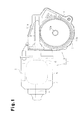
- FIG. 1 is a schematic view of a motor with a speed reduction mechanism according to one embodiment of the present invention.
- FIG. 2 is a schematic view showing a configuration of a motor main body of FIG. 1 .
- FIG. 3 is a schematic view in which the motor main body of FIG. 1 is developed to a planar form.
- FIGS. 4( a ) and 4( b ) are partially enlarged schematic views of the speed reduction mechanism of FIG. 1 .
- FIGS. 5( a ) and 5( b ) are partially enlarged schematic views of a speed reduction mechanism according to the prior art.
- FIG. 6 is a graph showing a relationship between an axial position and a meshing position in a worm of the speed reduction mechanism of FIG. 4 .
- FIG. 7 is a graph showing a relationship between an axial position and a meshing position in a worm of the conventional speed reduction mechanism of FIG. 5 .
- FIG. 8( a ) is a partially enlarged schematic view of a worm wheel in a further example as viewed from a radially outer side.
- FIG. 8( b ) is a partially enlarged schematic view of the worm wheel in a further example as viewed from an axial direction.
- FIG. 8( c ) is a partially enlarged schematic view of a worm in a further example as viewed from the axial direction.
- FIG. 1 to FIG. 4( b ) One embodiment embodying the present invention will be hereinafter described according to FIG. 1 to FIG. 4( b ) .
- a motor 1 with a speed reduction mechanism includes a motor main body 2 and a gear unit 3 .
- the motor 1 is used as a drive source for a vehicle wiper (not shown) that wipes a front glass and the like of the vehicle.
- the motor main body 2 includes a tubular yoke housing 4 with a bottom portion 4 a . At least one magnet 5 having four magnetic pole portions (two N poles and two S poles) is securely attached to an inner circumferential surface of the yoke housing 4 . In other words, the motor main body 2 includes two magnetic circuits. In the magnet 5 , the N pole and the S pole are alternately arranged in the circumferential direction of the yoke housing 4 .
- a rotor 6 which is an armature, is rotatably arranged on a radially inner side of the magnet 5 .
- the rotor 6 includes a rotation shaft 7 , a rotor core 63 , and a commutator 25 .
- a basal end of the rotation shaft 7 positioned near to the bottom portion 4 a of the yoke housing 4 is supported by a bearing 23 arranged at a center of the bottom portion 4 a .
- a distal end of the rotation shaft 7 extends toward the gear unit 3 from an opening of the yoke housing 4 .
- the rotor core 63 is arranged at a position facing the magnet 5 in a radial direction, and is fixed to the rotation shaft 7 so as to be integrally rotatable.
- the rotor core 63 includes 18 teeth 63 a radially extending towards the radially outer side with the rotation shaft 7 as a center.
- a slot 63 b is formed in a space between the teeth 63 a adjacent to each other in the circumferential direction of the rotor core 63 (see FIG. 3 ).
- the commutator 25 is fixed in an integrally rotatable manner to a portion of the rotation shaft 7 located nearer to the gear unit 3 than the rotor core 63 .
- the commutator 25 includes a cylindrical insulating body (not shown) made of insulating resin material and externally fitted to the rotation shaft 7 , and 18 segments 27 securely attached to an outer circumferential surface of the insulating body.
- Each segment 27 has a rectangular plate shape that is long in the axial direction of the rotation shaft 7 , and is curved along the outer circumferential surface of the insulating body.
- the 18 segments 27 are lined at an equal angular interval in the circumferential direction and are arranged to form a substantially cylindrical shape as a whole.
- the segments 27 adjacent to each other in the circumferential direction of the rotation shaft 7 are spaced apart in the circumferential direction of the rotation shaft 7 .
- the gear unit 3 includes a gear housing 11 coupled to and fixed with an opening edge of the yoke housing 4 .
- the gear housing 11 has an opening portion opened toward the yoke housing 4 .
- a brush holder 32 arranged on the radially outer side of the commutator 25 is fixed to such opening portion with a screw 33 .
- the brush holder 32 is made of an insulating resin material and has a circular shape.
- a cylindrical bearing holder 31 a extending along the axial direction of the rotation shaft 7 is arranged at the opening portion of the gear housing 11 .
- a circular shaped bearing 34 for supporting substantially a central part of the rotation shaft 7 is accommodated in the bearing holder 31 a .
- a ball bearing is used for the bearing 34 . This is because if a slide bearing such as a sintered metal bearing or the like is used for the bearing 34 , the necessary withstand load may not be obtained and the bearing 34 may break.
- the bearing 34 supports the rotation shaft 7 together with the bearing 23 .
- a screw toothed worm 8 is formed at a portion of the rotation shaft 7 that passes through the bearing 34 and extends into the gear housing 11 .
- the gear housing 11 includes a worm accommodating recess 11 a and a wheel accommodating recess 11 b communicating with the worm accommodating recess 11 a .
- the worm 8 is accommodated in the worm accommodating recess 11 a
- a circular plate shaped worm wheel is accommodated in the wheel accommodating recess 11 b while meshing with the worm 8 .
- the worm 8 and the worm wheel 12 configure a speed reduction mechanism 53 for reducing the rotation speed of the rotation shaft 7 .
- the worm 8 is made of metal.
- the worm wheel 12 is made of a self-lubricating resin having a linear molecular structure, and is made of POM (polyacetal) or PA (nylon), for example.
- a coupling hole 12 a is formed at a central part in the radial direction of the worm wheel 12 .
- An output shaft 54 having substantially circular column-shape is arranged in the coupling hole 12 a .
- the output shaft 54 extends in the axial direction of the worm wheel 12 and integrally rotates with the worm wheel 12 .
- a distal end of the output shaft 54 projects to the outside from the gear housing 11 .
- a basal end of a crank arm 55 is fixed to the distal end of the output shaft 54 .
- a vehicle wiper (not shown) is coupled to a distal end of the crank arm 55 by way of a link mechanism (not shown).
- FIG. 3 shows a schematic view in which the motor main body and a power supplying brush according to the present embodiment are developed to a planar form.
- each coil 65 is passed through the slot 63 b and wound around the rotor core 63 so as to be arranged across the four teeth 63 a lined continuously in the circumferential direction.
- a winding start end of each coil 65 is connected to one of the segments 27
- a winding finish end of each coil 65 is connected to another segment 27 adjacent in the circumferential direction to the segment 27 to which the winding start end is connected.
- the brush holder 32 (see FIG. 2 ) arranged in the gear unit 3 holds six power supplying brushes 70 , each having a square tubular shape and extending in the radial direction. Two of the six power supplying brushes 70 are common brushes 71 . Another two brushes are low speed driving brushes 72 . The remaining two brushes are high speed driving brushes 73 .
- the brushes 71 , 72 , 73 are arranged in the order of the common brush 71 , the high speed driving brush 73 , and the low speed driving brush 72 from the following side toward the preceding side in the rotating direction of the commutator 25 .
- the high speed driving brush 73 is arranged on the preceding side with respect to the common brush 71 in the rotating direction of the commutator 25
- the low speed driving brush 72 is arranged on the preceding side with respect to the high speed driving brush 73 in the rotating direction of the commutator 25 .
- Each power supplying brush 70 is biased toward the commutator 25 by a spring or the like (not shown), and the distal end thereof is pushed against the outer peripheral surface (i.e., a side surface on radially outer side of the segment 27 ) of the commutator 25 in a slidably contacting manner.
- the segment numbers “1” to “18” are given in order in the circumferential direction with respect to the eighteen segments 27 .
- the common brush 71 functions as a positive pole brush, and the low speed driving brush 72 and the high speed driving brush 73 function as negative pole brushes.
- a pigtail (not shown) is connected to each power supplying brush 70 , so that current is supplied to the power supplying brush 70 via such pig tail.
- the motor 1 configured as above, when the current is supplied to the rotor 6 via the common brush 71 and the low speed driving brush 72 , the rotor 6 is rotated at low speed.
- the current is supplied to the rotor 6 via the common brush 71 and the high speed driving brush 73 , the rotor 6 is rotated at high speed faster than at the time of the low speed driving.
- the rotation of the rotation shaft 7 is decelerated by the worm 8 and the worm wheel 12 and output from the output shaft 54 , whereby the vehicle wiper coupled to the crank arm 55 through the link mechanism is reciprocate turned.
- the width in the circumferential direction of the rotation shaft 7 and the arrangement position in the circumferential direction of the rotation shaft 7 of the six power supplying brushes 70 (i.e., two common brushes 71 , two low speed driving brushes 72 , and two high speed driving brushes 73 ) will now be described in detail. As shown in FIG.
- the width in the circumferential direction and the width in the circumferential direction of each brush 71 to 73 are set to repeat a one type short-circuit state (short-circuit state) in which only one type of power supplying brush 70 out of the three types of power supplying brushes 70 , which are the common brush 71 , the low speed driving brush 72 and the high speed driving brush 73 , short circuits two segments 27 adjacent in the circumferential direction and a non-short circuit state in which none of the power supplying brushes 70 short circuits the two segments 27 adjacent in the circumferential direction with the rotation of the rotor 6 .
- number P of magnetic pole portions of the magnet 5 is set to a value satisfying P ⁇ 4, and number of teeth 63 a and number of segments 27 are set to the same number.
- the value of S is set so that (2S/P) is an odd number.
- a width of the segment 27 is L 1
- an interval between the adjacent segments 27 is L 2
- a width of the common brush 71 is B 1
- a width of the low speed driving brush 72 is B 2
- a width of the high speed driving brush 73 is B 3 .
- each value is set to satisfy the following conditions.
- B 1> L 2, B 2> L 2, B 3> L 2 A ⁇ ( n ⁇ L 1+( n+ 1) ⁇ n 2) D 1>(( n ⁇ 1) ⁇ L 1+( n ⁇ 2) ⁇ L 2) D 2>( n 1 ⁇ L 1+( n 1 ⁇ 1) ⁇ L 2) D 3>( n 2 ⁇ L 1+( n 2 ⁇ 1) ⁇ L 2) n n 1+ n 2+1
- n is a number corresponding to the number of segments 27 arranged in an angular range of (360°/P).
- “n” is quotient obtained by dividing the number of segments 27 (i.e., same as number S of teeth 63 a ) arranged in the motor main body 2 with the number P of magnetic pole portions. If the quotient is not an integer, the rounded-up number becomes “n”.
- the common brush 71 , the low speed driving brush 72 , and the high speed driving brush 73 have the width in the circumferential direction and the arrangement position in the circumferential direction set to satisfy the above conditions.
- the width B 1 , B 2 , B 3 in the circumferential direction of each brush 71 to 73 is the same value and is narrower than the width in the circumferential direction of the segment 27 .
- the common brush 71 and the low speed driving brush 72 arranged with the high speed driving brush 73 in between are arranged at an interval of 90° same as the angular interval between the adjacent magnetic pole portions of the magnet 5 .
- the worm 8 and the worm wheel 12 of the present embodiment are set such that the pressure angle of the worm 8 is greater than the pressure angle of the worm wheel 12 .
- the pressure angle of the worm 8 is set to be greater than the pressure angle of the worm wheel 12 such that the maximum number of meshing teeth becomes smaller than or equal to n.
- the pressure angles are both ⁇ °, and the number of meshing teeth is changed between five (see FIG. 5( a ) ) and four (see FIG. 5( b ) ) by rotation (average number of meshing teeth is 4.1).
- the worm 8 and the worm wheel 12 shown in FIG. 4( a ) and FIG. 4( b ) are obtained by changing the pressure angles of the worm 51 and the worm wheel 52 .
- the pressure angle of the worm 8 is set to be greater than the pressure angle of the worm wheel 12 such that the maximum number of meshing teeth becomes smaller than or equal to four.
- the pressure angle of the worm wheel 12 is set to ⁇ ° and the pressure angle of the worm 8 is set to 1.76 ⁇ °, so that the maximum number of meshing teeth is four and the average of the number of meshing teeth is 3.7.
- a period (angle) in which the number of meshing teeth where the tooth 8 a of the worm 8 and a tooth 12 b of the worm wheel 12 mesh with each other (make contact) is four as shown in FIG. 4( a ) occupies 70 percent
- the pressure angle (1.76 ⁇ °) of the worm 8 of the present embodiment is set to a maximum angle while satisfying the relationship of the worm 8 and the worm wheel 12 (relationship of so-called worm gear). With such maximum angle, the tooth tip of the worm 8 becomes a triangular shape from a trapezoidal shape, but the diameter of the worm 8 does not become small.
- the pressure angle of the worm 8 in which the number of meshing teeth is always four is 1.2 ⁇ °.
- the meshing (contacting) area is illustrated with a black circle so that meshing (contacting) can be easily recognized visually.
- the worm 8 is made of metal and the worm wheel 12 is made of resin.
- FIG. 6 shows the relationship of the axial position and the meshing position in the worm 8 of the speed reduction mechanism 53 of FIG. 4 .
- FIG. 6 shows the meshing properties in the speed reduction mechanism 53 in which the worm 8 is made of metal and the worm wheel 12 is made of resin, and the pressure angle of the worm 8 is greater than the pressure angle of the worm wheel 12 .
- FIG. 7 shows a relationship of the axial position and the meshing position in the worm 51 of the conventional speed reduction mechanism of FIG. 5 . In other words, FIG.
- the “axial position” indicates the axial position of the worm
- the “meshing position” indicates the meshing position of the worm and the worm wheel as the position in the radial direction of the worm.
- the “output shaft center” indicates the position of a line orthogonal to the axis line of the worm and passing through the axis line of the worm wheel, in the axial direction of the worm. The value of the “meshing position” becomes greater the more the gearing position is closer to a tooth base of the worm.
- the meshing position takes a maximum value at the output shaft center and the meshing positions at the start of meshing and the end of meshing take substantially the same values in the graph showing the relationship of the axial position and the meshing position.
- the worm is made of metal and the worm wheel is made of resin, the deformation of the worm wheel is tolerated when the worm and the worm wheel mesh with each other.
- the range of the axial position between the start of meshing and the end of meshing becomes wide compared to when the worm and the worm wheel are both made of metal in the graph showing the relationship of the axial position and the meshing position.
- an axial position E 2 of the start of meshing of the worm 51 and the worm wheel 52 is relatively spaced apart with respect to an output shaft center 0 , so that an axial position D 2 of the end of meshing becomes relatively close with respect to the output shaft center 0 by such amount. Furthermore, a maximum value H 2 of the meshing position is relatively small, and an interval W 2 between the position of the maximum value H 2 and the output shaft center 0 is relatively large. In addition, a middle C 2 of the range from the axial position E 2 of the start of meshing to the axial position D 2 of the end of meshing is positioned on the axial position E 2 side of the start of meshing with respect to the output shaft center 0 .
- the axial position E 1 of the start of meshing of the worm 8 and the worm wheel 12 is closer with respect to the output shaft center 0 and the axial position D 1 of the end of meshing is farther away with respect to the output shaft center 0 compared to the conventional speed reduction mechanism. Furthermore, a maximum value H 1 of the meshing position is larger compared to the conventional speed reduction device, and an interval W 1 between the position of the maximum value H 2 and the output shaft center 0 is smaller compared to the conventional speed reduction device.
- the middle C 1 of the range from the axial position E 1 of the start of meshing to the axial position D 1 of the end of meshing is positioned on the axial position D 1 side of the end of meshing with respect to the output shaft center 0 .
- the surface pressure with respect to each tooth lowers when the number of meshing teeth increases to five, whereby the friction coefficient increases and the power loss at the meshing portion increases.
- the pressure angle of the worm 8 is set to be greater than the pressure angle of the worm wheel 12 so that the maximum number of meshing teeth becomes smaller than or equal to four, and hence the number of meshing teeth will not be five.
- the power loss can be reduced, and furthermore, the rotation transmission efficiency can be enhanced.
- the surface pressure with respect to each tooth increases when the number of meshing teeth is reduced as in the present embodiment, whereby the friction coefficient lowers and the power loss at the meshing portion can be reduced, and furthermore, the rotation transmission efficiency can be enhanced. Therefore, the efficiency of the motor 1 with the speed reduction mechanism can be enhanced.
- the speed reduction mechanism (motor 1 with speed reduction mechanism) with satisfactory rotation transmission efficiency can be easily manufactured with the manufacturing method of setting the pressure angle of the worm 8 in the above manner.
- the pressure angle of the worm 8 is set to 1.76 ⁇ °, which is the maximum angle, while satisfying the relationship of the worm 8 and the worm wheel 12 , that is, within a range in which the worm 8 and the worm wheel 12 function as the worm gear, and hence an average of the number of meshing teeth can be a minimum or 3.7.
- the power loss can be greatly reduced, and furthermore, the rotation transmission efficiency can be greatly enhanced.
- the worm wheel 12 is made of a self-lubricating resin having a linear molecular structure, so that the molecules at the surface of the worm wheel 12 are linearly lined along the direction of the pressure from the worm 8 when pressure is applied from the worm 8 , and friction is further reduced with respect to the pressure direction. Therefore, the power loss by the kinetic friction can be greatly reduced and the rotation transmission efficiency can be further enhanced.
- the speed reduction mechanism in which the number of meshing teeth is changed between five and four by rotation under the condition in which the pressure angles of the worm 8 and the worm wheel 12 are both ⁇ ° is described.
- the pressure angle of the worm 8 is to be set so that the maximum number of meshing teeth is smaller than or equal to n.
- the pressure angle of the worm 8 is to be set so that the maximum number of meshing teeth is smaller than or equal to five.
- the pressure angle of the worm 8 is to be set so that the maximum number of meshing teeth is smaller than or equal to three. In all cases, the power loss can be reduced, and furthermore, the rotation transmission efficiency can be enhanced.
- the pressure of the worm 8 is set to 1.76 ⁇ °, but is not limited thereto.
- the pressure angle of the worm 8 may be appropriately changed as long as the pressure angle of the worm 8 is set so that the maximum number of meshing teeth becomes smaller than or equal to n.
- the pressure angle of the worm 8 may be set to smaller than or equal to 1.76 ⁇ ° (e.g., 1.5 ⁇ °.
- the shape of the tooth 12 b of the worm wheel 12 may be a shape formed with a cutout 12 c on both ends in the axial direction when seen from the radially outer side, as shown in FIG. 8( a ) .
- both ends in the axial direction of the tooth 12 b of the worm wheel 12 may have a shape (shape formed with the cutout 12 c ) scraped so that the width becomes narrower towards the end in the axial direction, as opposed to a simple linear shape shown with a broken line in FIG. 8( a ) when seen from the radially outer side.
- the friction coefficient can be reduced by reduction in the contacting area and the friction coefficient can be further reduced while realizing satisfactory circumvention of the lubricating oil with the cutout 12 c.
- the distal end shape of the tooth 12 b of the worm wheel 12 may be a shape formed with a cutout 12 d so as to be tapered when seen from the axial direction, as shown in FIG. 8( b ) .
- the distal end of the tooth 12 b of the worm wheel 12 may have a shape (shape formed with the cutout 12 d ) scraped so as to be tapered, that is, the width rapidly becomes narrow, as opposed to a simple smooth curved shape shown with a broken line in FIG. 8( b ) when seen from the axial direction.
- the friction coefficient can be reduced by reduction in the contacting area and the friction coefficient can be further reduced while realizing satisfactory circumvention of the lubricating oil with the cutout 12 d.
- the distal end shape of the tooth 8 a of the worm 8 may be a shape formed with a cutout 8 b so as to be tapered when seen from the direction orthogonal to the axis, as shown in FIG. 8( c ) .
- the distal end of the tooth 8 a of the worm 8 may have a shape (shape formed with the cutout 8 b ) scraped so as to be tapered, that is, the width rapidly becomes narrow, as opposed to a simple linear shape shown with a broken line in FIG. 8( c ) when seen from the direction orthogonal to the axis.
- the friction coefficient can be reduced by reduction in the contacting area and the friction coefficient can be further reduced while realizing satisfactory circumvention of the lubricating oil with the cutout 8 b.
- the invention of the present application is embodied in the motor 1 with the speed reduction mechanism including the speed reduction mechanism (worm 8 and worm wheel 12 ) and the motor main body 2 for rotatably driving the worm 8 , but may be embodied as a speed reduction mechanism used in another device not including the motor main body 2 .
Landscapes
- Engineering & Computer Science (AREA)
- General Engineering & Computer Science (AREA)
- Mechanical Engineering (AREA)
- Power Engineering (AREA)
- Physics & Mathematics (AREA)
- Electromagnetism (AREA)
- Thermal Sciences (AREA)
- Gear Transmission (AREA)
- Connection Of Motors, Electrical Generators, Mechanical Devices, And The Like (AREA)
- Gears, Cams (AREA)
Abstract
Description
B1>L2,B2>L2,B3>L2
A<(n×L1+(n+1)×n2)
D1>((n−1)×L1+(n−2)×L2)
D2>(n1×L1+(n1−1)×L2)
D3>(n2×L1+(n2−1)×L2)
n=n1+n2+1
Claims (6)
Priority Applications (1)
| Application Number | Priority Date | Filing Date | Title |
|---|---|---|---|
| US14/841,925 US10024414B2 (en) | 2010-03-24 | 2015-09-01 | Speed reduction mechanism, motor with speed reduction mechanism, and method for producing speed reduction mechanism |
Applications Claiming Priority (5)
| Application Number | Priority Date | Filing Date | Title |
|---|---|---|---|
| JP2010-068383 | 2010-03-24 | ||
| JP2010068383 | 2010-03-24 | ||
| PCT/JP2011/056035 WO2011118448A1 (en) | 2010-03-24 | 2011-03-15 | Speed reduction mechanism, motor with speed reduction mechanism, and method for producing speed reduction mechanism |
| US201213635319A | 2012-09-14 | 2012-09-14 | |
| US14/841,925 US10024414B2 (en) | 2010-03-24 | 2015-09-01 | Speed reduction mechanism, motor with speed reduction mechanism, and method for producing speed reduction mechanism |
Related Parent Applications (2)
| Application Number | Title | Priority Date | Filing Date |
|---|---|---|---|
| US13/635,319 Continuation US9154015B2 (en) | 2010-03-24 | 2011-03-15 | Speed reduction mechanism, motor with speed reduction mechanism, and method for producing speed reduction mechanism |
| PCT/JP2011/056035 Continuation WO2011118448A1 (en) | 2010-03-24 | 2011-03-15 | Speed reduction mechanism, motor with speed reduction mechanism, and method for producing speed reduction mechanism |
Publications (2)
| Publication Number | Publication Date |
|---|---|
| US20150369353A1 US20150369353A1 (en) | 2015-12-24 |
| US10024414B2 true US10024414B2 (en) | 2018-07-17 |
Family
ID=44673005
Family Applications (2)
| Application Number | Title | Priority Date | Filing Date |
|---|---|---|---|
| US13/635,319 Active 2031-08-28 US9154015B2 (en) | 2010-03-24 | 2011-03-15 | Speed reduction mechanism, motor with speed reduction mechanism, and method for producing speed reduction mechanism |
| US14/841,925 Active 2032-04-12 US10024414B2 (en) | 2010-03-24 | 2015-09-01 | Speed reduction mechanism, motor with speed reduction mechanism, and method for producing speed reduction mechanism |
Family Applications Before (1)
| Application Number | Title | Priority Date | Filing Date |
|---|---|---|---|
| US13/635,319 Active 2031-08-28 US9154015B2 (en) | 2010-03-24 | 2011-03-15 | Speed reduction mechanism, motor with speed reduction mechanism, and method for producing speed reduction mechanism |
Country Status (7)
| Country | Link |
|---|---|
| US (2) | US9154015B2 (en) |
| JP (3) | JP5378593B2 (en) |
| KR (2) | KR101742045B1 (en) |
| CN (2) | CN102822564B (en) |
| BR (1) | BR112012023644B1 (en) |
| DE (1) | DE112011100994B4 (en) |
| WO (1) | WO2011118448A1 (en) |
Families Citing this family (17)
| Publication number | Priority date | Publication date | Assignee | Title |
|---|---|---|---|---|
| US9154015B2 (en) * | 2010-03-24 | 2015-10-06 | Asmo Co., Ltd. | Speed reduction mechanism, motor with speed reduction mechanism, and method for producing speed reduction mechanism |
| USD707739S1 (en) * | 2013-06-20 | 2014-06-24 | Asmo Co., Ltd. | Motor actuator |
| USD706325S1 (en) * | 2013-06-20 | 2014-06-03 | Asmo Co., Ltd. | Motor actuator |
| CN103883707B (en) * | 2014-04-21 | 2016-05-11 | 株洲齿轮有限责任公司 | Gear and gear train |
| DE102014210253B4 (en) * | 2014-05-28 | 2016-02-11 | Aktiebolaget Skf | Transmission for a height-adjustable shelf and method for changing a height of a shelf |
| USD774576S1 (en) * | 2015-04-20 | 2016-12-20 | SZ DJI Technology Co., Ltd. | Motor |
| JP6566245B2 (en) * | 2015-05-21 | 2019-08-28 | 株式会社ジェイテクト | Worm reducer and steering device |
| CN105106479A (en) * | 2015-10-13 | 2015-12-02 | 王俊英 | Traditional Chinese medicine for preventing and treating injury caused by extravasation of chemotherapeutic drugs and multifunctional stirring device |
| JP2017194127A (en) * | 2016-04-21 | 2017-10-26 | 株式会社ジェイテクト | Worm reducer and electric power steering device |
| JP2018084252A (en) * | 2016-11-21 | 2018-05-31 | マブチモーター株式会社 | Gear unit, reduction gear and motor with reduction gear |
| CN108245357B (en) * | 2016-12-28 | 2020-07-14 | 美好罗伯特有限公司 | Mechanical operating tables and hybrid operating room systems |
| EP3406939B1 (en) * | 2017-05-24 | 2020-04-01 | IMS Gear SE & Co. KGaA | Gear pair for a helical gear transmission or spur gear transmission, helical gear transmission or spur gear transmission with such a gear pairing and use of such a gear pair in helical gear transmissions and spur gear transmissions |
| JP6793609B2 (en) | 2017-08-30 | 2020-12-02 | 株式会社ミツバ | Motor with reduction mechanism |
| US20200255053A1 (en) | 2019-02-12 | 2020-08-13 | Steering Solutions Ip Holding Corporation | Worm shaft for steering assembly |
| JP7280763B2 (en) * | 2019-06-27 | 2023-05-24 | Kyb株式会社 | Worm shaft, worm reduction gear, and method for manufacturing worm shaft |
| DE102019217019A1 (en) * | 2019-11-05 | 2021-05-06 | Robert Bosch Gmbh | Gear teeth |
| CN112564353A (en) * | 2020-12-24 | 2021-03-26 | 贵阳万江航空机电有限公司 | Limiting structure and limiting method for end part of motor rotor |
Citations (30)
| Publication number | Priority date | Publication date | Assignee | Title |
|---|---|---|---|---|
| US1525642A (en) | 1922-09-28 | 1925-02-10 | Anthony B Cox | Gear teeth and method of designing the same |
| US1790607A (en) | 1929-03-11 | 1931-01-27 | Nikola Trbojevich | Steering gear |
| US4825715A (en) | 1986-12-17 | 1989-05-02 | Politechnika Rzeszowska Im. Ignacego Lukasiewicza | Gear transmission and method of machining its teeth |
| DE4041567A1 (en) | 1990-12-22 | 1992-06-25 | Zahnradfertigung Ott Gmbh U Co | Worm gear with two-part worm - has rounded engagement areas for teeth to reduce wear |
| US5389183A (en) | 1992-06-05 | 1995-02-14 | Mitsubishi Jukogyo Kabushiki Kaisha | Single-facer |
| JPH10220561A (en) | 1997-02-05 | 1998-08-21 | Polyplastics Co | Resin gear pair |
| JP2000097293A (en) | 1998-09-24 | 2000-04-04 | Yuuji Hanaguchi | Endless band type worm reduction gear |
| US6247376B1 (en) | 1999-07-13 | 2001-06-19 | Valeo Electrical Systems, Inc. | Rollable enveloped worm with two curve profile |
| JP2002139127A (en) | 2000-11-07 | 2002-05-17 | Nsk Ltd | Electric power steering gear |
| US6571655B2 (en) * | 2001-07-26 | 2003-06-03 | Juken Kogyo Co., Ltd. | Involute gear pair structure |
| US20040026160A1 (en) | 2002-08-06 | 2004-02-12 | Honda Giken Kogyo Kabushiki Kaisha | Electric power steering apparatus |
| JP2004066947A (en) | 2002-08-06 | 2004-03-04 | Honda Motor Co Ltd | Electric power steering device |
| JP2005003099A (en) | 2003-06-12 | 2005-01-06 | Honda Motor Co Ltd | Electric torque applying device and worm wheel machining method used in the device |
| JP2006177426A (en) | 2004-12-22 | 2006-07-06 | Mabuchi Motor Co Ltd | Small-size motor with reduction gear |
| RU2291337C1 (en) | 2005-06-01 | 2007-01-10 | Открытое акционерное общество "Электростальский завод тяжелого машиностроения" | Gap-free worm gear and method for cutting teeth of gap-free worm gear wheel |
| US7174865B2 (en) | 2004-07-19 | 2007-02-13 | Masami Sakita | Engine with a variable compression ratio |
| US20070227279A1 (en) | 2006-03-30 | 2007-10-04 | Honda Motor Co., Ltd. | Electric power steering apparatus equipped with worm gear mechanism |
| US20070295135A1 (en) | 2006-06-21 | 2007-12-27 | Asmo Co., Ltd. | Worm and motor apparatus having the same |
| CN201083251Y (en) | 2007-09-20 | 2008-07-09 | 国营江北机械厂 | Small mode number high power worm wheel worm gear pair |
| US7484438B2 (en) | 2006-12-12 | 2009-02-03 | Robert Murphy | Right angle driving tool |
| JP2009047267A (en) | 2007-08-21 | 2009-03-05 | Asmo Co Ltd | Worm and motor device |
| US7721616B2 (en) * | 2005-12-05 | 2010-05-25 | Gm Global Technology Operations, Inc. | Sprung gear set and method |
| US7798033B2 (en) * | 2002-11-14 | 2010-09-21 | Ims Gear Gmbh | Power-assisted steering having a gear mechanism |
| US7926381B2 (en) * | 2009-06-30 | 2011-04-19 | Hamilton Sundstrand Corporation | Idler gear for a generator |
| US8051737B2 (en) * | 2006-10-11 | 2011-11-08 | Johnson Electric S.A. | Worm gear drive |
| US8100028B2 (en) * | 2005-04-08 | 2012-01-24 | Tsutomu Miyaoku | Cornu's spiral tooth gear |
| US8250940B2 (en) * | 2006-07-20 | 2012-08-28 | Steering Solutions Ip Holding Corporation | System and method for controlling contact between members in operable communication |
| US8408353B2 (en) * | 2008-02-12 | 2013-04-02 | Jtekt Corporation | Vehicle steering apparatus |
| US20140291063A1 (en) | 2013-04-02 | 2014-10-02 | Mando Corporation | Electric power steering apparatus for vehicle and method of assembling the same |
| US9327357B2 (en) * | 2010-08-31 | 2016-05-03 | Aisin Seiki Kabushiki Kaisha | Gear machining apparatus, cutter and strain wave gearing device |
Family Cites Families (5)
| Publication number | Priority date | Publication date | Assignee | Title |
|---|---|---|---|---|
| KR19990005289U (en) * | 1997-07-15 | 1999-02-05 | 이영서 | Gas shutoff stabilizer using microcomputer circuit |
| JP2005012673A (en) | 2003-06-20 | 2005-01-13 | Shinko Electric Ind Co Ltd | Data communication system, IC tag and reader / writer |
| US7361118B2 (en) | 2004-07-20 | 2008-04-22 | Nabco Limited | Gear mechanism and reduction planetary gear |
| JP5100781B2 (en) | 2009-04-21 | 2012-12-19 | 本田技研工業株式会社 | Worm gear mechanism and electric power steering device equipped with the worm gear mechanism |
| US9154015B2 (en) * | 2010-03-24 | 2015-10-06 | Asmo Co., Ltd. | Speed reduction mechanism, motor with speed reduction mechanism, and method for producing speed reduction mechanism |
-
2011
- 2011-03-15 US US13/635,319 patent/US9154015B2/en active Active
- 2011-03-15 CN CN201180015716.3A patent/CN102822564B/en active Active
- 2011-03-15 CN CN201610023710.5A patent/CN105610276B/en active Active
- 2011-03-15 JP JP2012506951A patent/JP5378593B2/en active Active
- 2011-03-15 DE DE112011100994.1T patent/DE112011100994B4/en active Active
- 2011-03-15 BR BR112012023644A patent/BR112012023644B1/en active IP Right Grant
- 2011-03-15 KR KR1020127025056A patent/KR101742045B1/en active Active
- 2011-03-15 WO PCT/JP2011/056035 patent/WO2011118448A1/en not_active Ceased
- 2011-03-15 KR KR1020167001552A patent/KR101676330B1/en active Active
-
2013
- 2013-09-24 JP JP2013197155A patent/JP5711331B2/en active Active
-
2015
- 2015-03-03 JP JP2015041288A patent/JP5977387B2/en active Active
- 2015-09-01 US US14/841,925 patent/US10024414B2/en active Active
Patent Citations (31)
| Publication number | Priority date | Publication date | Assignee | Title |
|---|---|---|---|---|
| US1525642A (en) | 1922-09-28 | 1925-02-10 | Anthony B Cox | Gear teeth and method of designing the same |
| US1790607A (en) | 1929-03-11 | 1931-01-27 | Nikola Trbojevich | Steering gear |
| US4825715A (en) | 1986-12-17 | 1989-05-02 | Politechnika Rzeszowska Im. Ignacego Lukasiewicza | Gear transmission and method of machining its teeth |
| DE4041567A1 (en) | 1990-12-22 | 1992-06-25 | Zahnradfertigung Ott Gmbh U Co | Worm gear with two-part worm - has rounded engagement areas for teeth to reduce wear |
| US5389183A (en) | 1992-06-05 | 1995-02-14 | Mitsubishi Jukogyo Kabushiki Kaisha | Single-facer |
| JPH10220561A (en) | 1997-02-05 | 1998-08-21 | Polyplastics Co | Resin gear pair |
| JP2000097293A (en) | 1998-09-24 | 2000-04-04 | Yuuji Hanaguchi | Endless band type worm reduction gear |
| US6247376B1 (en) | 1999-07-13 | 2001-06-19 | Valeo Electrical Systems, Inc. | Rollable enveloped worm with two curve profile |
| JP2002139127A (en) | 2000-11-07 | 2002-05-17 | Nsk Ltd | Electric power steering gear |
| US6571655B2 (en) * | 2001-07-26 | 2003-06-03 | Juken Kogyo Co., Ltd. | Involute gear pair structure |
| US20040026160A1 (en) | 2002-08-06 | 2004-02-12 | Honda Giken Kogyo Kabushiki Kaisha | Electric power steering apparatus |
| JP2004066947A (en) | 2002-08-06 | 2004-03-04 | Honda Motor Co Ltd | Electric power steering device |
| US6976556B2 (en) | 2002-08-06 | 2005-12-20 | Honda Giken Kogyo Kabushiki Kaisha | Electric power steering apparatus |
| US7798033B2 (en) * | 2002-11-14 | 2010-09-21 | Ims Gear Gmbh | Power-assisted steering having a gear mechanism |
| JP2005003099A (en) | 2003-06-12 | 2005-01-06 | Honda Motor Co Ltd | Electric torque applying device and worm wheel machining method used in the device |
| US7174865B2 (en) | 2004-07-19 | 2007-02-13 | Masami Sakita | Engine with a variable compression ratio |
| JP2006177426A (en) | 2004-12-22 | 2006-07-06 | Mabuchi Motor Co Ltd | Small-size motor with reduction gear |
| US8100028B2 (en) * | 2005-04-08 | 2012-01-24 | Tsutomu Miyaoku | Cornu's spiral tooth gear |
| RU2291337C1 (en) | 2005-06-01 | 2007-01-10 | Открытое акционерное общество "Электростальский завод тяжелого машиностроения" | Gap-free worm gear and method for cutting teeth of gap-free worm gear wheel |
| US7721616B2 (en) * | 2005-12-05 | 2010-05-25 | Gm Global Technology Operations, Inc. | Sprung gear set and method |
| US20070227279A1 (en) | 2006-03-30 | 2007-10-04 | Honda Motor Co., Ltd. | Electric power steering apparatus equipped with worm gear mechanism |
| US20070295135A1 (en) | 2006-06-21 | 2007-12-27 | Asmo Co., Ltd. | Worm and motor apparatus having the same |
| US8250940B2 (en) * | 2006-07-20 | 2012-08-28 | Steering Solutions Ip Holding Corporation | System and method for controlling contact between members in operable communication |
| US8051737B2 (en) * | 2006-10-11 | 2011-11-08 | Johnson Electric S.A. | Worm gear drive |
| US7484438B2 (en) | 2006-12-12 | 2009-02-03 | Robert Murphy | Right angle driving tool |
| JP2009047267A (en) | 2007-08-21 | 2009-03-05 | Asmo Co Ltd | Worm and motor device |
| CN201083251Y (en) | 2007-09-20 | 2008-07-09 | 国营江北机械厂 | Small mode number high power worm wheel worm gear pair |
| US8408353B2 (en) * | 2008-02-12 | 2013-04-02 | Jtekt Corporation | Vehicle steering apparatus |
| US7926381B2 (en) * | 2009-06-30 | 2011-04-19 | Hamilton Sundstrand Corporation | Idler gear for a generator |
| US9327357B2 (en) * | 2010-08-31 | 2016-05-03 | Aisin Seiki Kabushiki Kaisha | Gear machining apparatus, cutter and strain wave gearing device |
| US20140291063A1 (en) | 2013-04-02 | 2014-10-02 | Mando Corporation | Electric power steering apparatus for vehicle and method of assembling the same |
Non-Patent Citations (3)
| Title |
|---|
| International Preliminary Report on Patentability for related PCT/JP2011/056035 dated Mar. 6, 2012. |
| International Search Report for related PCT Application No. PCT/JP2011/056035 dated May 17, 2011. |
| Office Action dated Apr. 27, 2015 for related Chinese Application. |
Also Published As
| Publication number | Publication date |
|---|---|
| BR112012023644A2 (en) | 2016-08-02 |
| BR112012023644B1 (en) | 2020-04-07 |
| KR101676330B1 (en) | 2016-11-15 |
| DE112011100994B4 (en) | 2023-03-16 |
| KR101742045B1 (en) | 2017-05-31 |
| KR20130016238A (en) | 2013-02-14 |
| WO2011118448A1 (en) | 2011-09-29 |
| CN102822564A (en) | 2012-12-12 |
| DE112011100994T5 (en) | 2013-02-07 |
| CN105610276A (en) | 2016-05-25 |
| JP2015111008A (en) | 2015-06-18 |
| CN105610276B (en) | 2018-09-14 |
| KR20160017097A (en) | 2016-02-15 |
| US20130008276A1 (en) | 2013-01-10 |
| JP5711331B2 (en) | 2015-04-30 |
| JP5378593B2 (en) | 2013-12-25 |
| US20150369353A1 (en) | 2015-12-24 |
| US9154015B2 (en) | 2015-10-06 |
| CN102822564B (en) | 2016-02-10 |
| JP5977387B2 (en) | 2016-08-24 |
| JPWO2011118448A1 (en) | 2013-07-04 |
| JP2013253705A (en) | 2013-12-19 |
Similar Documents
| Publication | Publication Date | Title |
|---|---|---|
| US10024414B2 (en) | Speed reduction mechanism, motor with speed reduction mechanism, and method for producing speed reduction mechanism | |
| US8899120B2 (en) | Linear actuator | |
| JP4551623B2 (en) | Linear actuator | |
| US20140159527A1 (en) | Electric motor | |
| US8633626B2 (en) | DC motor | |
| JP2009047267A (en) | Worm and motor device | |
| US20110169371A1 (en) | Motor and brush configuration method | |
| EP1271751A1 (en) | Electric machine having rhombic permanent magnets | |
| JP2008019902A (en) | Linear motion actuator | |
| US20070152522A1 (en) | Rotating Electrical Machine with a Transmission and a Driving Apparatus Using the Same | |
| JP2011130613A (en) | Electric motor | |
| KR20090026473A (en) | Stepping motor | |
| WO2010107082A1 (en) | Electric generator | |
| US9905983B2 (en) | Brush for an electric motor | |
| JP2005030545A (en) | Worm for motor with reducing mechanism | |
| US6580237B2 (en) | Direct-current motor and manufacturing method of the same | |
| JP6945488B2 (en) | Reduction mechanism and motor with reduction mechanism | |
| CN214756024U (en) | Rear fixed shaft type linear stepping motor | |
| KR20120007923A (en) | Stepping motor | |
| JP5353060B2 (en) | Gear mechanism | |
| JP2008259316A (en) | Motor and driving device for vehicle opening/closing bodies using the motor | |
| JP2025126425A (en) | Motor, and motor equipped with speed reducer | |
| JP2001327121A (en) | Motor with deceleration mechanism | |
| JP2024057904A (en) | Worm reducer |
Legal Events
| Date | Code | Title | Description |
|---|---|---|---|
| AS | Assignment |
Owner name: ASMO CO., LTD., JAPAN Free format text: ASSIGNMENT OF ASSIGNORS INTEREST;ASSIGNORS:HORIKAWA, MASAYA;YAGI, HIDEYUKI;SOGA, ITARU;SIGNING DATES FROM 20120809 TO 20120815;REEL/FRAME:036467/0604 |
|
| STCF | Information on status: patent grant |
Free format text: PATENTED CASE |
|
| AS | Assignment |
Owner name: DENSO CORPORATION, JAPAN Free format text: MERGER;ASSIGNOR:ASMO CO., LTD;REEL/FRAME:047927/0127 Effective date: 20180401 |
|
| MAFP | Maintenance fee payment |
Free format text: PAYMENT OF MAINTENANCE FEE, 4TH YEAR, LARGE ENTITY (ORIGINAL EVENT CODE: M1551); ENTITY STATUS OF PATENT OWNER: LARGE ENTITY Year of fee payment: 4 |
|
| MAFP | Maintenance fee payment |
Free format text: PAYMENT OF MAINTENANCE FEE, 8TH YEAR, LARGE ENTITY (ORIGINAL EVENT CODE: M1552); ENTITY STATUS OF PATENT OWNER: LARGE ENTITY Year of fee payment: 8 |