US10022651B2 - Device and method for the contact of a gas phase with a liquid medium - Google Patents
Device and method for the contact of a gas phase with a liquid medium Download PDFInfo
- Publication number
- US10022651B2 US10022651B2 US15/034,284 US201415034284A US10022651B2 US 10022651 B2 US10022651 B2 US 10022651B2 US 201415034284 A US201415034284 A US 201415034284A US 10022651 B2 US10022651 B2 US 10022651B2
- Authority
- US
- United States
- Prior art keywords
- liquid medium
- brush
- housing
- bristles
- conveying device
- Prior art date
- Legal status (The legal status is an assumption and is not a legal conclusion. Google has not performed a legal analysis and makes no representation as to the accuracy of the status listed.)
- Active, expires
Links
- 239000007788 liquid Substances 0.000 title claims abstract description 83
- 238000000034 method Methods 0.000 title claims abstract description 9
- 239000013013 elastic material Substances 0.000 claims description 3
- 238000001704 evaporation Methods 0.000 description 12
- 230000008020 evaporation Effects 0.000 description 12
- 238000009434 installation Methods 0.000 description 7
- 239000003595 mist Substances 0.000 description 6
- 239000012071 phase Substances 0.000 description 6
- 239000000203 mixture Substances 0.000 description 4
- 239000000126 substance Substances 0.000 description 4
- XLYOFNOQVPJJNP-UHFFFAOYSA-N water Substances O XLYOFNOQVPJJNP-UHFFFAOYSA-N 0.000 description 4
- 230000001376 precipitating effect Effects 0.000 description 3
- 239000007787 solid Substances 0.000 description 3
- 238000004821 distillation Methods 0.000 description 2
- 238000005086 pumping Methods 0.000 description 2
- 230000002745 absorbent Effects 0.000 description 1
- 239000002250 absorbent Substances 0.000 description 1
- 238000001816 cooling Methods 0.000 description 1
- 238000012423 maintenance Methods 0.000 description 1
- 230000008929 regeneration Effects 0.000 description 1
- 238000011069 regeneration method Methods 0.000 description 1
- 238000000926 separation method Methods 0.000 description 1
- 239000012808 vapor phase Substances 0.000 description 1
Images

Classifications
-
- B—PERFORMING OPERATIONS; TRANSPORTING
- B01—PHYSICAL OR CHEMICAL PROCESSES OR APPARATUS IN GENERAL
- B01D—SEPARATION
- B01D19/00—Degasification of liquids
- B01D19/0042—Degasification of liquids modifying the liquid flow
- B01D19/0052—Degasification of liquids modifying the liquid flow in rotating vessels, vessels containing movable parts or in which centrifugal movement is caused
-
- B—PERFORMING OPERATIONS; TRANSPORTING
- B01—PHYSICAL OR CHEMICAL PROCESSES OR APPARATUS IN GENERAL
- B01D—SEPARATION
- B01D1/00—Evaporating
- B01D1/22—Evaporating by bringing a thin layer of the liquid into contact with a heated surface
- B01D1/222—In rotating vessels; vessels with movable parts
- B01D1/223—In rotating vessels; vessels with movable parts containing a rotor
- B01D1/227—In rotating vessels; vessels with movable parts containing a rotor with brushes
-
- B—PERFORMING OPERATIONS; TRANSPORTING
- B01—PHYSICAL OR CHEMICAL PROCESSES OR APPARATUS IN GENERAL
- B01D—SEPARATION
- B01D19/00—Degasification of liquids
- B01D19/0005—Degasification of liquids with one or more auxiliary substances
-
- B—PERFORMING OPERATIONS; TRANSPORTING
- B01—PHYSICAL OR CHEMICAL PROCESSES OR APPARATUS IN GENERAL
- B01D—SEPARATION
- B01D3/00—Distillation or related exchange processes in which liquids are contacted with gaseous media, e.g. stripping
- B01D3/34—Distillation or related exchange processes in which liquids are contacted with gaseous media, e.g. stripping with one or more auxiliary substances
- B01D3/343—Distillation or related exchange processes in which liquids are contacted with gaseous media, e.g. stripping with one or more auxiliary substances the substance being a gas
- B01D3/346—Distillation or related exchange processes in which liquids are contacted with gaseous media, e.g. stripping with one or more auxiliary substances the substance being a gas the gas being used for removing vapours, e.g. transport gas
-
- B—PERFORMING OPERATIONS; TRANSPORTING
- B01—PHYSICAL OR CHEMICAL PROCESSES OR APPARATUS IN GENERAL
- B01D—SEPARATION
- B01D2259/00—Type of treatment
- B01D2259/10—Gas phase, e.g. by using aerosols
Definitions
- the invention relates to a device for the contact of a gas phase with a liquid medium, and to a method for operating the device.
- the contact of a gas phase with a liquid medium can be used, in practice, in many fields.
- the contact of a gas phase with a liquid can be used in order to remove volatile substances from a liquid. This makes it possible for example, on the one hand, for the liquid to be cleaned and, on the other hand, for the volatile components dissolved in the liquid to be collected and, for example following regeneration, to be reused.
- the removal of volatile components from a liquid can take place in a conventional manner for example by distillation.
- a liquid containing, in addition to a component of relatively low volatility, at least one more highly volatile component is heated, and therefore it is predominantly the more highly volatile component which evaporates, whereas the component of relatively low volatility remains.
- the evaporated, more highly volatile component can be recovered in the form of a liquid from the vapor phase by means of cooling.
- the disadvantage of such a distillation method is the amount of time and energy required for it.
- volatile components can be removed from a liquid by means of a fixed-bed installation.
- the liquid here is directed via a fixed bed, e.g. a packed column.
- Gas e.g. air
- the disadvantage with such an arrangement is that the fixed-bed installation can become encrusted with precipitating solids and the installation requires high-outlay measures in order to be free of the encrustations, so as to restore functional capability of the installation.
- the contact of a gas phase with a liquid medium can also be used, for example, to moisten the gas with the liquid medium.
- a large evaporation surface area is required, and this is not usually available.
- a device for the contact of a gas phase with a volatile medium comprises:
- the at least one gas inlet and the fan are suitable for generating a gas stream from a lower portion of the device to an upper portion of the device;
- a distributing means is provided in the upper region of the housing, said distributing means being suitable for distributing over the brush the liquid medium which has been raised by the conveying device.
- the conveying device is designed in the form of an Archimedean screw, wherein the brush is fitted on the conveying device and can be rotated therewith.
- the conveying device may contain some other pumping device.
- the central region of the housing is rotationally symmetrical, particularly preferably cylindrical.
- the device comprises at least one second inflow for the liquid medium.
- the device advantageously also comprises at least one drive, which is suitable for driving the conveying device and for rotating the brush.
- the device in the central region, has at least one part which projects in the direction of the conveying device and is designed such that at least part of it comes into contact with the brush.
- the bristles preferably consist of an elastic material.
- the bristles have a porous surface.
- the device has bristles which are hollow.
- the brush and the conveying device here are particularly advantageously designed such that the hollow bristles are supplied, at least in part, with the liquid medium from the conveying device.
- a method for the contact of a gas phase with a liquid medium has one of the devices described above and comprises the following steps:
- the at least one gas inlet and the fan generate a gas stream from a lower portion of the device to an upper portion of the device
- the liquid medium distributed over the upper surface of the brush is directed back by way of the brush, counter to the gas stream, into the lower region.
- the liquid medium passes into the upper region of the device via the conveying device and is distributed over the brush by way of the distributing means.
- the rotary drive for the conveying device preferably simultaneously causes the brush to rotate.
- the distributed liquid moves back into the lower region of the device on account of gravitational force and wets the bristles of the brush in the process.
- the bristles here serve as an evaporation surface for the liquid medium.
- the above conveying device straightforwardly allows volatile components to be separated off from the liquid medium, since the individual bristles of the brush are wetted by the liquid medium and thus serve as an evaporation surface for the liquid medium. It is therefore the case that there is a very large surface area available for the separation of volatile components from the liquid medium.
- the elasticity of the bristles gives rise to only small amounts of encrustation, if any at all, as a result of solids precipitating on the bristles.
- the brush and the rotary movement thereof makes it possible for the liquid medium introduced into the device to have a longer residence time than, for example, in conventional fixed-bed installations. More thorough removal of volatile components from the liquid medium can thus be achieved.
- Providing at least one part which projects in the direction of the conveying device makes it possible, in addition, to generate, by way of the movement of the bristles, a fine mist from the liquid medium, said mist forming an additional evaporation surface area for the volatile components dissolved in the liquid medium. The removal of volatile components from the liquid medium can thus be further improved.
- the above device can likewise be used to moisten a gas stream effectively, since the individual bristles of the brush provide a large evaporation surface area and the air stream which is directed through the brush can entrain the evaporated liquid medium.
- the device can advantageously be used for moistening air with water in order to create for example pleasant climatic conditions in a room.
- Providing the brush and the rotary movement thereof provides the liquid medium introduced into the device with a long residence time, and the gas stream introduced can thus be moistened effectively.
- Providing at least one part which projects in the direction of the conveying device makes it possible, in addition, to generate, by way of the movement of the bristles, a fine mist from the liquid medium, said mist forming an additional evaporation surface area for the liquid medium and thus allowing a higher level of saturation of the gas with the liquid medium.
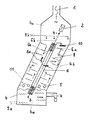
- FIGURE shows a schematic illustration of one embodiment of the device.
- the device shown in the FIGURE comprises a housing 4 having a lower region 4 a , a central region 4 b and an upper region 4 c .
- the central region 4 b here is tilted in relation to the lower region 4 a and the upper region 4 c .
- the housing also has gas inlets 5 and is open at the upper end, and it is therefore possible to provide a fan 1 in order to generate a gas stream from the gas inlets 5 to the upper region 4 c of the device.
- the gas used may be, for example, air, but also any other gas or gas mixture.
- the device has a plurality of first inflows 9 b , which are arranged above a brush 8 .
- the housing 4 is also wetted in the central region 4 b with the liquid medium introduced, and serves as an evaporation surface for said medium.
- the device also has, in the lower region 4 a , a second inflow 9 a for the liquid medium, for example water or an absorbent, and an outflow 7 .
- the brush 8 is fitted on a tube 6 c of a conveying device 6 , which is designed in the form of an Archimedean screw, and comprises bristles 8 a .
- the bristles 8 a here preferably consist of an elastic material and particularly preferably have porous surfaces. It is also possible here for the bristles 8 a to be hollow.
- the Archimedean screw 6 runs parallel to the central region 4 b of the device and comprises, in addition to the tube 6 c , a worm 6 a and a drive axle 6 b , which can be driven by a motor 2 and is mounted in a rotatable manner by means of bearing 3 . Both the worm 6 a and the tube 6 c can be rotated by the axle 6 b . Since the brush 8 is fitted on the tube 6 c of the Archimedean screw 6 , said brush can also be rotated. It is not imperative, however, for the conveying device to be designed in the form of an Archimedean screw. It is also possible to use, for example, a conveying device which contains some other pumping device.
- a liquid medium is directed into the lower region 4 a of the device via the inflow 9 b and optionally via the further, second inflow 9 a .
- the liquid medium collected in the lower region 4 a is raised by means of the Archimedean screw 6 and fed to a distributing means 10 , which is arranged in the upper region 4 c of the housing 4 .
- the distributing means 10 here distributes the raised liquid medium over the upper surface of the brush 8 , and therefore the liquid medium is directed back into the lower region 4 a , on account of gravitational force, by way of the brush 8 .
- the rotary movement of the Archimedean screw 6 at the same time also causes the brush 8 to rotate.
- the fan 1 and the gas inlets 5 generate a gas stream from the gas inlets 5 to the upper region 4 c of the device.
- the surfaces of the individual bristles 8 a of the brush 8 are wetted by the liquid medium distributed over the upper surface of the brush 8 and serve as an evaporation surface for the liquid medium. While the device is constructed in compact form, it is thus possible for the area of the evaporation surface to be increased by a multiple in relation to the surface area of the liquid medium collected in the lower region 4 a of the device. This makes possible, for example, more thorough removal of volatile substances from the liquid medium. It is likewise thereby possible for the gas stream to be moistened effectively with the liquid medium and for the device to be used for moistening, for example, air.
- the bristles 8 a scrape over the surface of the central region 4 b of the housing 4 .
- the elasticity of the bristles 8 a and the continuous movement of the bristles 8 a result in only very small amounts of encrustation of the bristles, if any at all, as a result of solids precipitating from the liquid medium, as a result of which the amount of maintenance required for the device is reduced to a minimum in relation to, for example, a fixed-bed installation.
- the encrustation can be reduced, in addition, by providing in the central region 4 b of the housing 4 at least one part 11 which projects in the direction of the axle 6 b , since at least part of the projecting part 11 comes into contact with the bristles 8 a of the brush 8 and encourages these, in addition, to oscillate.
- the oscillating movement of the bristles 8 a gives rise, in addition, to a fine liquid-medium droplet mist, which forms an additional evaporation surface area for the liquid medium.
- Providing the at least one projecting part 11 thus makes possible even more thorough removal of the volatile substances from the liquid medium.
- the liquid medium freed of the volatile substances moves back into the lower region 4 a of the device on account of gravitational force and can be directed away via the outflow 7 .
- the saturation of the gas with the liquid medium can be further increased in this way.
- the body of the brush 8 and the tube 6 c may be made in one piece.
- the tube 6 b serves as a body for the brush 8 , and the bristles 8 a are fitted directly on the tube 6 c . It is particularly advantageous here if the bristles 8 a are hollow and the tube 6 c is designed such that the bristles 8 a can be supplied directly with the liquid medium conveyed in the Archimedean screw 6 .
- the gas blown out on the upper side of the device by the fan 1 may contain, for example, volatile components which have been separated from the liquid medium, and it is possible for these components to be collected and then, for example, regenerated, reused or disposed of.
- the gas or gas mixture blown out on the upper side of the device by the fan 1 is mixed with the evaporated liquid medium and, in the case of air moistened with water, to be used for example for creating pleasant climatic conditions in a room.
Landscapes
- Chemical & Material Sciences (AREA)
- Chemical Kinetics & Catalysis (AREA)
- Structures Of Non-Positive Displacement Pumps (AREA)
- Gas Separation By Absorption (AREA)
- Disinfection, Sterilisation Or Deodorisation Of Air (AREA)
- Vaporization, Distillation, Condensation, Sublimation, And Cold Traps (AREA)
Abstract
A device for the contact of a gas phase with a liquid medium, and a method for operating the device. The liquid medium here is directed into the device and some of it is raised by means of a conveying device. The liquid medium raised is distributed over a rotating brush by way of a distributing means. At least one gas inlet and a fan here generate a gas stream from a lower portion of the device to an upper portion of the device. The liquid medium distributed over the upper surface of the brush is directed back by way of the brush, counter to the gas stream, into the lower region.
Description
The invention relates to a device for the contact of a gas phase with a liquid medium, and to a method for operating the device.
The contact of a gas phase with a liquid medium can be used, in practice, in many fields. For example, the contact of a gas phase with a liquid can be used in order to remove volatile substances from a liquid. This makes it possible for example, on the one hand, for the liquid to be cleaned and, on the other hand, for the volatile components dissolved in the liquid to be collected and, for example following regeneration, to be reused.
The removal of volatile components from a liquid can take place in a conventional manner for example by distillation. In this case, a liquid containing, in addition to a component of relatively low volatility, at least one more highly volatile component is heated, and therefore it is predominantly the more highly volatile component which evaporates, whereas the component of relatively low volatility remains. The evaporated, more highly volatile component can be recovered in the form of a liquid from the vapor phase by means of cooling. The disadvantage of such a distillation method is the amount of time and energy required for it.
As an alternative, it is also possible for volatile components to be removed from a liquid by means of a fixed-bed installation. The liquid here is directed via a fixed bed, e.g. a packed column. Gas, e.g. air, is introduced in counterflow through the fixed bed in order for the volatile component to be separated off. The disadvantage with such an arrangement is that the fixed-bed installation can become encrusted with precipitating solids and the installation requires high-outlay measures in order to be free of the encrustations, so as to restore functional capability of the installation.
The contact of a gas phase with a liquid medium can also be used, for example, to moisten the gas with the liquid medium. In specific terms, it is thus possible to moisten for example air with water in order to create more pleasant climatic conditions in a room. In order for the air to be moistened sufficiently at room temperature, a large evaporation surface area is required, and this is not usually available.
Briefly stated, a device for the contact of a gas phase with a volatile medium comprises:
-
- a housing having a lower region, a central region and an upper region;
- at least one gas inlet;
- a fan;
- at least one first inflow for the liquid medium;
- at least one outflow, which is arranged in the lower region;
- a conveying device, which is suitable for raising some of the liquid medium from the lower region; and
- a brush, which comprises bristles and can be rotatable,
wherein the at least one gas inlet and the fan are suitable for generating a gas stream from a lower portion of the device to an upper portion of the device; and
a distributing means is provided in the upper region of the housing, said distributing means being suitable for distributing over the brush the liquid medium which has been raised by the conveying device.
In one embodiment, the conveying device is designed in the form of an Archimedean screw, wherein the brush is fitted on the conveying device and can be rotated therewith. As an alternative, the conveying device may contain some other pumping device.
In a preferred embodiment, the central region of the housing is rotationally symmetrical, particularly preferably cylindrical.
In an advantageous embodiment, the device comprises at least one second inflow for the liquid medium.
The device advantageously also comprises at least one drive, which is suitable for driving the conveying device and for rotating the brush.
In a preferred embodiment, the device, in the central region, has at least one part which projects in the direction of the conveying device and is designed such that at least part of it comes into contact with the brush.
The bristles preferably consist of an elastic material. In a preferred embodiment of the invention, the bristles have a porous surface. In a further advantageous embodiment, the device has bristles which are hollow. The brush and the conveying device here are particularly advantageously designed such that the hollow bristles are supplied, at least in part, with the liquid medium from the conveying device.
A method for the contact of a gas phase with a liquid medium, has one of the devices described above and comprises the following steps:
-
- directing the liquid medium into the device;
- raising some of the liquid medium collected in the lower region;
- distributing the raised liquid medium over the brush, wherein the brush rotates;
the at least one gas inlet and the fan generate a gas stream from a lower portion of the device to an upper portion of the device; and
the liquid medium distributed over the upper surface of the brush is directed back by way of the brush, counter to the gas stream, into the lower region.
The liquid medium passes into the upper region of the device via the conveying device and is distributed over the brush by way of the distributing means. The rotary drive for the conveying device preferably simultaneously causes the brush to rotate. The distributed liquid moves back into the lower region of the device on account of gravitational force and wets the bristles of the brush in the process. The bristles here serve as an evaporation surface for the liquid medium.
The above conveying device straightforwardly allows volatile components to be separated off from the liquid medium, since the individual bristles of the brush are wetted by the liquid medium and thus serve as an evaporation surface for the liquid medium. It is therefore the case that there is a very large surface area available for the separation of volatile components from the liquid medium.
In contrast to the conventional fixed-bed installations, the elasticity of the bristles gives rise to only small amounts of encrustation, if any at all, as a result of solids precipitating on the bristles. Providing in a central region of the housing at least one part which projects in the direction of the axle and is designed such that at least part of it comes into contact with the brush makes it possible, in addition, for the bristles to be made to move, and the encrustation of the brush can be reduced further.
Providing the brush and the rotary movement thereof makes it possible for the liquid medium introduced into the device to have a longer residence time than, for example, in conventional fixed-bed installations. More thorough removal of volatile components from the liquid medium can thus be achieved. Providing at least one part which projects in the direction of the conveying device makes it possible, in addition, to generate, by way of the movement of the bristles, a fine mist from the liquid medium, said mist forming an additional evaporation surface area for the volatile components dissolved in the liquid medium. The removal of volatile components from the liquid medium can thus be further improved.
The above device can likewise be used to moisten a gas stream effectively, since the individual bristles of the brush provide a large evaporation surface area and the air stream which is directed through the brush can entrain the evaporated liquid medium. The device can advantageously be used for moistening air with water in order to create for example pleasant climatic conditions in a room.
Providing the brush and the rotary movement thereof provides the liquid medium introduced into the device with a long residence time, and the gas stream introduced can thus be moistened effectively. Providing at least one part which projects in the direction of the conveying device makes it possible, in addition, to generate, by way of the movement of the bristles, a fine mist from the liquid medium, said mist forming an additional evaporation surface area for the liquid medium and thus allowing a higher level of saturation of the gas with the liquid medium.
Further properties and advantages of the device and the method will be made clear by way of the following description of specific embodiments, with reference being made to the drawing. In the latter, the FIGURE shows a schematic illustration of one embodiment of the device.
The device shown in the FIGURE comprises a housing 4 having a lower region 4 a, a central region 4 b and an upper region 4 c. The central region 4 b here is tilted in relation to the lower region 4 a and the upper region 4 c. The housing also has gas inlets 5 and is open at the upper end, and it is therefore possible to provide a fan 1 in order to generate a gas stream from the gas inlets 5 to the upper region 4 c of the device. The gas used may be, for example, air, but also any other gas or gas mixture.
In the advantageous embodiment shown, the device has a plurality of first inflows 9 b, which are arranged above a brush 8. This means that the housing 4 is also wetted in the central region 4 b with the liquid medium introduced, and serves as an evaporation surface for said medium. The device also has, in the lower region 4 a, a second inflow 9 a for the liquid medium, for example water or an absorbent, and an outflow 7.
The brush 8 is fitted on a tube 6 c of a conveying device 6, which is designed in the form of an Archimedean screw, and comprises bristles 8 a. The bristles 8 a here preferably consist of an elastic material and particularly preferably have porous surfaces. It is also possible here for the bristles 8 a to be hollow.
The Archimedean screw 6 runs parallel to the central region 4 b of the device and comprises, in addition to the tube 6 c, a worm 6 a and a drive axle 6 b, which can be driven by a motor 2 and is mounted in a rotatable manner by means of bearing 3. Both the worm 6 a and the tube 6 c can be rotated by the axle 6 b. Since the brush 8 is fitted on the tube 6 c of the Archimedean screw 6, said brush can also be rotated. It is not imperative, however, for the conveying device to be designed in the form of an Archimedean screw. It is also possible to use, for example, a conveying device which contains some other pumping device.
A liquid medium is directed into the lower region 4 a of the device via the inflow 9 b and optionally via the further, second inflow 9 a. In a second step, the liquid medium collected in the lower region 4 a is raised by means of the Archimedean screw 6 and fed to a distributing means 10, which is arranged in the upper region 4 c of the housing 4. The distributing means 10 here distributes the raised liquid medium over the upper surface of the brush 8, and therefore the liquid medium is directed back into the lower region 4 a, on account of gravitational force, by way of the brush 8.
The rotary movement of the Archimedean screw 6 at the same time also causes the brush 8 to rotate. In addition, the fan 1 and the gas inlets 5 generate a gas stream from the gas inlets 5 to the upper region 4 c of the device.
The surfaces of the individual bristles 8 a of the brush 8 are wetted by the liquid medium distributed over the upper surface of the brush 8 and serve as an evaporation surface for the liquid medium. While the device is constructed in compact form, it is thus possible for the area of the evaporation surface to be increased by a multiple in relation to the surface area of the liquid medium collected in the lower region 4 a of the device. This makes possible, for example, more thorough removal of volatile substances from the liquid medium. It is likewise thereby possible for the gas stream to be moistened effectively with the liquid medium and for the device to be used for moistening, for example, air.
As the brush 8 rotates, the bristles 8 a scrape over the surface of the central region 4 b of the housing 4. The elasticity of the bristles 8 a and the continuous movement of the bristles 8 a result in only very small amounts of encrustation of the bristles, if any at all, as a result of solids precipitating from the liquid medium, as a result of which the amount of maintenance required for the device is reduced to a minimum in relation to, for example, a fixed-bed installation. The encrustation can be reduced, in addition, by providing in the central region 4 b of the housing 4 at least one part 11 which projects in the direction of the axle 6 b, since at least part of the projecting part 11 comes into contact with the bristles 8 a of the brush 8 and encourages these, in addition, to oscillate. The oscillating movement of the bristles 8 a gives rise, in addition, to a fine liquid-medium droplet mist, which forms an additional evaporation surface area for the liquid medium.
Providing the at least one projecting part 11 thus makes possible even more thorough removal of the volatile substances from the liquid medium. The liquid medium freed of the volatile substances moves back into the lower region 4 a of the device on account of gravitational force and can be directed away via the outflow 7.
During use for moistening gas or gas mixtures, the saturation of the gas with the liquid medium can be further increased in this way. For the purpose of increasing the saturation level, it is also possible, in addition, to heat the gas introduced into the device. It is likewise possible to heat the liquid medium, in order to promote evaporation of the liquid medium.
In a further-reaching advantageous embodiment of the device, the body of the brush 8 and the tube 6 c may be made in one piece. The tube 6 b serves as a body for the brush 8, and the bristles 8 a are fitted directly on the tube 6 c. It is particularly advantageous here if the bristles 8 a are hollow and the tube 6 c is designed such that the bristles 8 a can be supplied directly with the liquid medium conveyed in the Archimedean screw 6. It is thus possible, on the one hand, in addition for liquid medium to be applied to the housing wall 4 in the central region 4 b, as a result of which said central region becomes the evaporation surface for the liquid medium, and, on the other hand, in the case of the projecting part 11 being provided, for an additional fine droplet mist to be generated. This makes possible, for example, particularly thorough removal of volatile components from the volatile medium. It is thus also possible for the saturation of gas or gas mixtures with the liquid medium to be further increased.
The gas blown out on the upper side of the device by the fan 1 may contain, for example, volatile components which have been separated from the liquid medium, and it is possible for these components to be collected and then, for example, regenerated, reused or disposed of.
It is likewise possible for the gas or gas mixture blown out on the upper side of the device by the fan 1 to be mixed with the evaporated liquid medium and, in the case of air moistened with water, to be used for example for creating pleasant climatic conditions in a room.
Claims (20)
1. A device for the contact of a gas phase with a liquid medium, comprising the following:
a housing, having a lower region, a central region and an upper region;
at least one gas inlet;
a fan;
at least one first inflow for the liquid medium;
at least one outflow, which is arranged in the lower region;
a conveying device, which is suitable for raising some of the liquid medium from the lower region; and
a rotatable brush, which comprises bristles;
wherein the at least one gas inlet and the fan are suitable for generating a gas stream from a lower portion of the device to an upper portion of the device; and
a distributing means is provided in the upper region of the housing, said distributing means being suitable for distributing over the brush the liquid medium which is raised by the conveying device.
2. The device as claimed in claim 1 , wherein the conveying device is designed in the form of an Archimedean screw and the brush is fitted on the conveying device and can be rotated therewith.
3. The device as claimed in claim 1 , wherein the central region of the housing is essentially rotationally symmetrical and the brush is fitted in a rotatable manner into the central region of the housing.
4. The device as claimed in claim 1 , wherein the device comprises at least one second inflow for the liquid medium.
5. The device as claimed in claim 1 , wherein the device also comprises at least one drive, which is suitable for driving the conveying device and/or rotating the brush.
6. The device as claimed in claim 1 , wherein the device, in the central region, has at least one part which projects in the direction of the conveying device and is designed such that at least part of it comes into contact with the brush.
7. The device as claimed in claim 1 , wherein the bristles consist of an elastic material.
8. The device as claimed in claim 1 , wherein the bristles have a porous surface.
9. The device as claimed in claim 1 , wherein the bristles are hollow.
10. The device as claimed in claim 9 , wherein the brush and the conveying device (6) are designed such that the bristles are supplied, at least in part, with the liquid medium from the conveying device.
11. A method for the contact of a gas phase with a liquid medium, having a device as claimed in claim 1 and comprising the following steps:
directing the liquid medium into the device;
raising some of the liquid medium collected in the lower region; and
distributing the raised liquid medium over the brush, wherein the brush rotates;
the at least one gas inlet and the fan generate a gas stream from a lower portion of the device to an upper portion of the device; and the liquid medium distributed over the brush is directed back by way of the brush, counter to the gas stream, into the lower region.
12. The method as claimed in claim 11 , wherein the brush rotates together with the conveying device.
13. The device as claimed in claim 1 , wherein the central region of the housing is cylindrical and the brush is fitted in a rotational manner into the central region of the housing.
14. The device as claimed in claim 2 , wherein the central region of the housing is essentially rotationally symmetrical and the brush is fitted in a rotatable manner into the central region of the housing.
15. The device as claimed in claim 2 , wherein the device comprises at least one second inflow for the liquid medium.
16. The device as claimed in claim 3 , wherein the device comprises at least one second inflow for the liquid medium.
17. The device as claimed in claim 13 , wherein the device comprises at least one second inflow for the liquid medium.
18. The device as claimed in claim 2 , wherein the device also comprises at least one drive, which is suitable for driving the conveying device and/or rotating the brush.
19. The device as claimed in claim 3 , wherein the device also comprises at least one drive, which is suitable for driving the conveying device and/or rotating the brush.
20. The device as claimed in claim 4 , wherein the device also comprises at least one drive, which is suitable for driving the conveying device and/or rotating the brush.
Applications Claiming Priority (4)
| Application Number | Priority Date | Filing Date | Title |
|---|---|---|---|
| DE102013222343 | 2013-11-04 | ||
| DE102013222343.9 | 2013-11-04 | ||
| DE102013222343.9A DE102013222343A1 (en) | 2013-11-04 | 2013-11-04 | Apparatus and method for the contact of a gas phase with a liquid medium |
| PCT/EP2014/073101 WO2015063076A1 (en) | 2013-11-04 | 2014-10-28 | Device and method for the contact of a gas phase with a liquid medium |
Publications (2)
| Publication Number | Publication Date |
|---|---|
| US20160296857A1 US20160296857A1 (en) | 2016-10-13 |
| US10022651B2 true US10022651B2 (en) | 2018-07-17 |
Family
ID=51844703
Family Applications (1)
| Application Number | Title | Priority Date | Filing Date |
|---|---|---|---|
| US15/034,284 Active 2035-08-05 US10022651B2 (en) | 2013-11-04 | 2014-10-28 | Device and method for the contact of a gas phase with a liquid medium |
Country Status (5)
| Country | Link |
|---|---|
| US (1) | US10022651B2 (en) |
| EP (1) | EP2922602B1 (en) |
| CN (1) | CN106102854B (en) |
| DE (1) | DE102013222343A1 (en) |
| WO (1) | WO2015063076A1 (en) |
Cited By (2)
| Publication number | Priority date | Publication date | Assignee | Title |
|---|---|---|---|---|
| US20180087785A1 (en) * | 2015-04-30 | 2018-03-29 | Matthias Enzenhofer | Humidity Management Device And Method |
| US11331591B2 (en) * | 2016-06-22 | 2022-05-17 | Matthias Enzenhofer | Humidity management device, potable water generation system and method |
Citations (7)
| Publication number | Priority date | Publication date | Assignee | Title |
|---|---|---|---|---|
| GB548281A (en) | 1940-03-27 | 1942-10-05 | British Celanese | Improved method and apparatus for the production of finely-divided solid particles |
| DE1117051B (en) | 1960-03-21 | 1961-11-09 | Buckau Wolf Maschf R | Atomizing device for pasty masses |
| DE1262908B (en) | 1964-04-28 | 1968-03-07 | Uta Patentverwaltungs G M B H | Drying tower with dust dusters in the upper area and brushing system for the tower walls |
| US3737378A (en) | 1969-02-01 | 1973-06-05 | Kao Corp | Deodorizing method by film and steam distillation |
| US4276124A (en) | 1975-07-17 | 1981-06-30 | Haakon Haakonsen | Distillation system for sea water |
| US4867849A (en) | 1988-07-25 | 1989-09-19 | Cova Dario R | Purification of alkyl glyoxylate |
| US5741397A (en) * | 1996-01-11 | 1998-04-21 | Kraver; Mark P. | Dental waste separator |
Family Cites Families (9)
| Publication number | Priority date | Publication date | Assignee | Title |
|---|---|---|---|---|
| US11801A (en) * | 1854-10-10 | Improvement in the construction of sugar-boilers | ||
| GB190928868A (en) * | 1909-12-10 | 1910-12-12 | John Radcliffe | Improvements in the Process of and Apparatus for the Recovery of Tar, Tar-vapour and Ammonia from Distillation Gases. |
| DE687142C (en) * | 1936-05-12 | 1940-01-24 | Edward Charles D Yarmett | Distillation process and facility |
| DE1144999B (en) * | 1953-04-24 | 1963-03-07 | Hovalwerk Ag Ospelt | Device for dust separation in gas pipes using a centrifugal brush |
| SE331269B (en) * | 1968-10-31 | 1970-12-21 | E Carlsson | |
| DE3122026A1 (en) * | 1981-06-03 | 1983-01-05 | Paul 7107 Bad Friedrichshall Christian | Apparatus for separating off liquids and solids from gases |
| DE3713651A1 (en) * | 1987-04-23 | 1988-11-17 | Thomas F Burger | AIR CLEANER |
| JP4143218B2 (en) * | 1999-04-23 | 2008-09-03 | 株式会社日本触媒 | Method for preventing polymerization in thin film evaporator and thin film evaporator |
| DE10207101A1 (en) * | 2002-02-20 | 2003-08-28 | Ruediger Ufermann | Room humidifier has composite fan and Archimedes screw water conveyor forming jets of water through which room air is passed and recirculated |
-
2013
- 2013-11-04 DE DE102013222343.9A patent/DE102013222343A1/en not_active Withdrawn
-
2014
- 2014-10-28 WO PCT/EP2014/073101 patent/WO2015063076A1/en not_active Ceased
- 2014-10-28 US US15/034,284 patent/US10022651B2/en active Active
- 2014-10-28 EP EP14792450.0A patent/EP2922602B1/en active Active
- 2014-10-28 CN CN201480072169.6A patent/CN106102854B/en not_active Expired - Fee Related
Patent Citations (7)
| Publication number | Priority date | Publication date | Assignee | Title |
|---|---|---|---|---|
| GB548281A (en) | 1940-03-27 | 1942-10-05 | British Celanese | Improved method and apparatus for the production of finely-divided solid particles |
| DE1117051B (en) | 1960-03-21 | 1961-11-09 | Buckau Wolf Maschf R | Atomizing device for pasty masses |
| DE1262908B (en) | 1964-04-28 | 1968-03-07 | Uta Patentverwaltungs G M B H | Drying tower with dust dusters in the upper area and brushing system for the tower walls |
| US3737378A (en) | 1969-02-01 | 1973-06-05 | Kao Corp | Deodorizing method by film and steam distillation |
| US4276124A (en) | 1975-07-17 | 1981-06-30 | Haakon Haakonsen | Distillation system for sea water |
| US4867849A (en) | 1988-07-25 | 1989-09-19 | Cova Dario R | Purification of alkyl glyoxylate |
| US5741397A (en) * | 1996-01-11 | 1998-04-21 | Kraver; Mark P. | Dental waste separator |
Non-Patent Citations (1)
| Title |
|---|
| Search Report. |
Cited By (3)
| Publication number | Priority date | Publication date | Assignee | Title |
|---|---|---|---|---|
| US20180087785A1 (en) * | 2015-04-30 | 2018-03-29 | Matthias Enzenhofer | Humidity Management Device And Method |
| US10808949B2 (en) * | 2015-04-30 | 2020-10-20 | Matthias Enzenhofer | Humidity management device and method |
| US11331591B2 (en) * | 2016-06-22 | 2022-05-17 | Matthias Enzenhofer | Humidity management device, potable water generation system and method |
Also Published As
| Publication number | Publication date |
|---|---|
| WO2015063076A1 (en) | 2015-05-07 |
| CN106102854A (en) | 2016-11-09 |
| DE102013222343A1 (en) | 2015-05-07 |
| CN106102854B (en) | 2018-03-09 |
| EP2922602A1 (en) | 2015-09-30 |
| US20160296857A1 (en) | 2016-10-13 |
| EP2922602B1 (en) | 2018-06-06 |
Similar Documents
| Publication | Publication Date | Title |
|---|---|---|
| US11318415B2 (en) | Humidity conditioning device and humidity conditioning method | |
| WO2012105654A1 (en) | Seawater desalination device | |
| US10022651B2 (en) | Device and method for the contact of a gas phase with a liquid medium | |
| US20210107027A1 (en) | Atomizer and humidity controller | |
| US11331591B2 (en) | Humidity management device, potable water generation system and method | |
| KR102221628B1 (en) | Fludized Bed Adsorption Unit | |
| CN205549628U (en) | Scraper type thin film evaporator for heat sensitive materials | |
| JP5291766B2 (en) | Gas-liquid contact type air cleaner | |
| EP3289289B1 (en) | Humidity management device and methods | |
| CN207745534U (en) | Liquid vaporising unit | |
| JP2007245014A (en) | Desalination equipment | |
| JP2019502090A (en) | Highly efficient systems and equipment in mass transfer | |
| KR101585982B1 (en) | dust collecting deodorizer | |
| US1806021A (en) | Humidifier | |
| JP2002143601A (en) | Solvent concentration method and apparatus | |
| CN101905109A (en) | A device and method for wet scrubbing, purification and recovery of organic waste gas | |
| JP2010107095A (en) | Air conditioner | |
| RU2147527C1 (en) | Method of and device for cleaning contaminated gas | |
| JP2006239639A (en) | Air cleaner | |
| GB2144650A (en) | Gas scrubber | |
| JPH05317578A (en) | Waste water evaporating device for dry cleaning | |
| JP4971037B2 (en) | Moisture adjustment method and organic thin film formation method using the same | |
| JP2005007213A (en) | Solvent recovering apparatus | |
| JP4782154B2 (en) | Solvent recovery device and cleaning device | |
| JP2007160232A (en) | Air cleaner |
Legal Events
| Date | Code | Title | Description |
|---|---|---|---|
| STCF | Information on status: patent grant |
Free format text: PATENTED CASE |
|
| MAFP | Maintenance fee payment |
Free format text: PAYMENT OF MAINTENANCE FEE, 4TH YR, SMALL ENTITY (ORIGINAL EVENT CODE: M2551); ENTITY STATUS OF PATENT OWNER: SMALL ENTITY Year of fee payment: 4 |