US10022573B2 - Fall arrest system safety device - Google Patents
Fall arrest system safety device Download PDFInfo
- Publication number
- US10022573B2 US10022573B2 US14/618,452 US201514618452A US10022573B2 US 10022573 B2 US10022573 B2 US 10022573B2 US 201514618452 A US201514618452 A US 201514618452A US 10022573 B2 US10022573 B2 US 10022573B2
- Authority
- US
- United States
- Prior art keywords
- shaft
- drum
- safety device
- coiler member
- plastically deformable
- Prior art date
- Legal status (The legal status is an assumption and is not a legal conclusion. Google has not performed a legal analysis and makes no representation as to the accuracy of the status listed.)
- Active, expires
Links
- 230000007246 mechanism Effects 0.000 claims abstract description 46
- 238000004804 winding Methods 0.000 claims description 3
- 239000006096 absorbing agent Substances 0.000 abstract description 72
- 230000005540 biological transmission Effects 0.000 abstract description 11
- 229910001220 stainless steel Inorganic materials 0.000 description 5
- 239000010935 stainless steel Substances 0.000 description 5
- 208000027418 Wounds and injury Diseases 0.000 description 2
- 230000007613 environmental effect Effects 0.000 description 2
- 238000007789 sealing Methods 0.000 description 2
- 238000010521 absorption reaction Methods 0.000 description 1
- 230000015572 biosynthetic process Effects 0.000 description 1
- 230000006835 compression Effects 0.000 description 1
- 238000007906 compression Methods 0.000 description 1
- 238000010276 construction Methods 0.000 description 1
- 230000007797 corrosion Effects 0.000 description 1
- 238000005260 corrosion Methods 0.000 description 1
- 230000006378 damage Effects 0.000 description 1
- 239000000428 dust Substances 0.000 description 1
- 238000005755 formation reaction Methods 0.000 description 1
- 208000014674 injury Diseases 0.000 description 1
- 239000000463 material Substances 0.000 description 1
- 230000002265 prevention Effects 0.000 description 1
- 239000000725 suspension Substances 0.000 description 1
Images
Classifications
-
- A—HUMAN NECESSITIES
- A62—LIFE-SAVING; FIRE-FIGHTING
- A62B—DEVICES, APPARATUS OR METHODS FOR LIFE-SAVING
- A62B35/00—Safety belts or body harnesses; Similar equipment for limiting displacement of the human body, especially in case of sudden changes of motion
- A62B35/04—Safety belts or body harnesses; Similar equipment for limiting displacement of the human body, especially in case of sudden changes of motion incorporating energy absorbing means
-
- A—HUMAN NECESSITIES
- A62—LIFE-SAVING; FIRE-FIGHTING
- A62B—DEVICES, APPARATUS OR METHODS FOR LIFE-SAVING
- A62B35/00—Safety belts or body harnesses; Similar equipment for limiting displacement of the human body, especially in case of sudden changes of motion
- A62B35/0093—Fall arrest reel devices
-
- B—PERFORMING OPERATIONS; TRANSPORTING
- B66—HOISTING; LIFTING; HAULING
- B66D—CAPSTANS; WINCHES; TACKLES, e.g. PULLEY BLOCKS; HOISTS
- B66D5/00—Braking or detent devices characterised by application to lifting or hoisting gear, e.g. for controlling the lowering of loads
- B66D5/32—Detent devices
-
- F—MECHANICAL ENGINEERING; LIGHTING; HEATING; WEAPONS; BLASTING
- F16—ENGINEERING ELEMENTS AND UNITS; GENERAL MEASURES FOR PRODUCING AND MAINTAINING EFFECTIVE FUNCTIONING OF MACHINES OR INSTALLATIONS; THERMAL INSULATION IN GENERAL
- F16F—SPRINGS; SHOCK-ABSORBERS; MEANS FOR DAMPING VIBRATION
- F16F7/00—Vibration-dampers; Shock-absorbers
- F16F7/12—Vibration-dampers; Shock-absorbers using plastic deformation of members
- F16F7/123—Deformation involving a bending action, e.g. strap moving through multiple rollers, folding of members
Definitions
- the present invention relates to a fall arrest system safety device and in particular to a device including a drum upon which a safety line is used including an energy absorber arrangement to absorb the energy of a fall arrest event.
- Fall arrest systems are used to prevent personnel working at height from suffering injury as a result of falling. Fall arrest systems are often referred to as height safety systems or fall prevention systems. Frequently such systems include a so called safety block arranged to be suspended overhead from an anchor structure. Such arrangements typically include a drum upon which a safety line is wound; a speed responsive mechanism arranged to inhibit the drum rotation above a predetermined rotational speed and an energy absorber device arranged to be activated if a load above a predetermined threshold is deployed when the speed responsive mechanism is deployed.
- the energy absorber devices are typically either friction brake devices or plastically deformable metallic strip arrangements that are plastically deformed during deployment in order to absorb energy.
- the present invention provides a safety device for use in a fall arrest system, the safety device comprising:
- a safety line drum mounted for rotation
- a speed responsive engagement mechanism responsive to the speed of rotation of the drum, which is activated, above a predetermined rotational speed of the drum
- a rotational transmission member which transmission member is coupled, via the speed responsive engagement mechanism, when activated, to rotate with the drum; the energy absorber arrangement being activated in response to operation of the rotational transmission member.
- the transmission member is typically a shaft which is coupled so as to rotate in unison with the drum only when the speed responsive engagement mechanism is engaged. Accordingly it is preferred that the transmission member comprises a shaft and preferably that the drum is arranged in a first movement regime to rotate independently of and about the shaft; and in a second movement regime to rotate in unison with the shaft.
- the drum is preferably mounted on the shaft and provided with bearings permitting the drum to rotate independently about the shaft in the first movement regime.
- the speed responsive engagement mechanism is preferably positioned intermediate the drum and the energy absorber arrangement. In this way the energy absorber is mounted outboard the speed responsive engagement mechanism. This enables the energy absorber to be removed and replaced without dismantling of the speed responsive engagement mechanism.
- the invention provides a safety device comprising:
- a safety line drum mounted for rotation
- a speed responsive engagement mechanism responsive to the speed of rotation of the drum and at least a portion of which is carried by the shaft and, which is activated, above a predetermined rotational speed of the drum in order to couple rotation of the drum to the energy absorber arrangement;
- speed responsive engagement mechanism arrangement is mounted intermediate the drum and the energy absorber arrangement.
- the transmission member comprises a shaft and the shaft has a portion arranged to cooperate with the energy absorber to deploy or operate the energy absorber.
- the respective portion of the shaft engages with a drive member comprising the energy absorber arrangement.
- the transmission member comprises a shaft and the energy absorber arrangement is arranged to be fitted about the end of the shaft.
- the elongate element having a first end attached to the coiler member and a second free end remote from the first end; the elongate element extending past the deformer structure at apposition intermediate the first and second ends; relative rotation of the coiler member and deformer structure causing the elongate element to be drawn past the deformer structure, plastically deforming the elongate element and winding the elongate element coil form about the coiler member.
- the elongate element is stored in coil form prior to drawing through the deformer structure.
- the coiler member comprises an inner member arranged for relative rotation with respect to an outer member; the outer member comprising the deformer structure.
- the energy absorber arrangement may comprise a friction disc brake arrangement.
- the transmission member comprises a shaft and the shaft extends through from the interior of a housing via a dividing wall in the housing; the housing containing the drum and the speed responsive engagement mechanism, wherein the energy absorber arrangement is mounted onto the shaft externally of the housing separated from the drum and speed responsive engagement mechanism by means of the dividing wall.
- the drum and the speed responsive engagement mechanism (and the re-spooler mechanism, where present) can be held in a sealed environment which does not need to be disturbed in order to maintain or replace the energy absorber arrangement which lies outside the housing.
- a safety device for use in a fall arrest system, the safety device comprising:
- a safety line drum mounted for rotation
- a speed responsive engagement mechanism responsive to the speed of rotation of the drum, which is activated, above a predetermined rotational speed of the drum
- a transmission member comprising a shaft capable of rotating with the drum and which extends through from the interior of a housing via a dividing wall in the housing
- the energy absorber arrangement is mounted onto the shaft externally of the housing separated from the drum and speed responsive engagement mechanism by means of the dividing wall.
- the housing is sealed from the environment externally of the housing, a seal being provided for the shaft and the dividing wall.
- an enclosure or housing for the energy absorber is provided, this being secured with respect to the housing containing the drum and the speed responsive engagement mechanism.
- the speed responsive engagement mechanism comprises a ratchet and pawl mechanism.
- the ratchet comprises a ratchet disc and there is relative rotation between the ratchet disc and the pawls.
- the pawls are carried to rotate with the drum.
- the device further comprises a rewinding (or re-spooling) mechanism arranged to rotate the drum to rewind the safety line onto the drum in the absence of sufficient tension in the safety line to pay out the line.
- a rewinding (or re-spooling) mechanism arranged to rotate the drum to rewind the safety line onto the drum in the absence of sufficient tension in the safety line to pay out the line.
- FIG. 1 is a schematic sectional view of a first embodiment of a fall arrest system safety device in accordance with the invention
- FIG. 2 is an exploded perspective view of the device of FIG. 1 ;
- FIG. 3 is a schematic view of a preferred embodiment of the energy absorber arrangement in accordance with the invention.
- FIG. 4 is a schematic sectional view of a second embodiment of a fall arrest system safety device in accordance with the invention.
- FIG. 5 is an exploded perspective view of the device of FIG. 4 ;
- FIG. 6 is a perspective view of the embodiment of FIGS. 4 and 5 ;
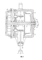
- FIG. 7 is a schematic sectional view of an embodiment similar to the embodiment of FIG. 1 with a recoil brake arrangement.
- a safety device 1 in accordance with the invention having a main housing 2 within which is mounted a shaft 5 and a rotary drum 3 mounted to be able to rotate about the shaft by means of bearings 4 .
- the device includes an attachment eye 43 for suspension from an anchor structure as is known for prior art safety block devices.
- a safety line wound on the drum passes out of the device via an exit portion 44 .
- a reduced diameter proximal end 6 of the shaft 5 is held in a tail bearing 7 in the side of the main housing 2 .
- a rewinding or re-spooling mechanism 8 Within the main housing 2 adjacent and connected to the rotary drum 3 is a rewinding or re-spooling mechanism 8 .
- the rewinding mechanism applies a small torque to the drum 3 causing it to contra-rotate in a direction which tends to rewind the safety line back onto the drum.
- One preferred type of rewinding mechanism is a coiled spring of the clockspring type. Many suitable rewinding mechanisms are known in the art and will therefore not be described in detail herein.
- the rewinding mechanism is provided with a shaft bearing 18
- a speed responsive engagement arrangement comprising a pawl 10 and ratchet 11 arrangement.
- the pawl and ratchet arrangement may for example be of a type as described in WO2008/007119.
- the pawls 10 are mounted for rotation with the drum 3 by means of a pivoting boss 27 that is received in a respective boss recess 12 , 13 provided in the drum 3 and a facing plate 14 which is fixed to the rotary drum 3 by means of securing bolts 15 .
- the ratchet plate 11 is secured for rotation with the shaft 5 .
- the safety line is able to pay out from the drum unabated. In this regime, the pawls 10 rotate with the drum 3 and do not engage the ratchet 11 teeth formations.
- the ratchet 11 remains fixed to the shaft 5 and the shaft 5 and ratchet 11 do note rotate with the drum 3 .
- the main housing 2 is closed by an end plate 16 which is bolted to the main housing 2 by means of bolts 17 .
- the distal end 21 of the shaft 5 extends through a bush 29 secured in an axial aperture in the end plate 16 .
- the bush 29 permits rotation of the shaft 5 with respect to the end plate 16 and main housing 2 .
- the distal end of the shaft 5 is D shaped in section, having a flat 28 that provides a keying engagement connection with a connecting coiler member of an energy absorber as will be described.
- a shaft seal 19 seals the shaft 5 . This arrangement ensures that the interior of the main housing 2 is sealed from the exterior environment of the device, even though the shaft extends through the end plate 16 which acts as a dividing wall.
- An energy absorber housing 20 is bolted to the main housing 2 and contains an energy absorber cartridge 22 containing an energy absorber strip 23 .
- the energy absorber strip 23 is loaded into the cartridge 22 in un-deployed form. When deployed during a fall arrest event the energy absorber strip is deployed to a deformed state in order to absorb the energy of a fall. This will be described in greater detail herein.
- the energy absorber cartridge 22 comprises a coiler member 35 and a circular annular deformer ring 33 arranged concentrically about the coiler member 35 and having an inner surface 33 a and an outer surface 33 b .
- the coiler member 35 has a central aperture 32 which is D shaped in section in order to engage with the D shaped sectioned distal end 21 of the shaft 5 . In this way the shaft 5 and coiler member 35 are keyed to be coupled to drivingly rotationally engage when the absorber cartridge is loaded in position.
- the energy absorber strip 23 is arranged to absorb energy in response to relative rotational movement of the shaft 5 and coupled coiler member 35 with respect to the deformer ring 33 .
- the energy absorber is arranged to absorb energy in response to anti-clockwise rotation of the shaft ends 21 relative to the deformer ring 33 .
- the energy absorber strip comprises a stainless steel strip 23 having a constant thickness and width along its entire length. In operation, the energy absorber absorbs energy by plastic deformation of the stainless steel strip 23 .
- the coiler member 35 is provided with a key aperture 32 (in the form of D shaped aperture) for keying and driving engagement with the end 21 of shaft 5 .
- the coiler member 35 is mounted on the shaft end 21 so that the coiler member 35 rotates with the shaft end 21 relative to the deformer ring 33 .
- An annular space 38 is defined between the coiler member 35 and the inner surface 33 a of the deformer ring 33 .
- the ring 33 has a deformer slot 33 c passing through the ring 33 and oriented tangentially to the inner surface 33 a of the ring 33 .
- the slot 33 c is slightly wider than the thickness of the strip 34 .
- the slot 33 c has a flat clockwise face 33 d and a parallel flat anticlockwise face 33 e , and the anticlockwise face 33 e of the slot 33 is tangential to the inner surface 33 a of the ring 33 .
- the slot 33 c has a curved entry surface 33 f where the clockwise surface 33 d of the slot 33 c contacts the outer surface 33 b of the ring 33 and a curved exit surface 33 g where the clockwise surface 33 d of the slot 33 c contacts the inner surface 33 a of the ring 33 .
- the curved entry surface 33 f and the curved exit surface 33 g are separated by the flat clockwise face 33 d.
- the strip 23 has a first end 23 a secured to the coiler 35 and a free end 23 b .
- the strip 23 passes through the slot 33 c , and rest of the strip, ending in the free end 23 b , is coiled around the outer surface 33 b of the deformer ring 33 .
- An upstanding outer circular wall 36 is provided for the absorber cartridge concentrically about the deformer ring 33 so that an annular strip storage channel 37 is formed between the outer surface 33 b of the ring 33 and the wall 36 .
- the wall 36 and the deformer ring 33 stand upwardly from a backplate of the absorber cartridge 22 .
- the absorber cartridge 22 is secured by means of bolts to the end plate 16 of the main housing and provides protection against environmental effects such as weathering or dust.
- the safety line pays out from the drum 3 at a higher speed than in normal ‘safe’ pay out situations.
- the ratchet 11 causes the pawl 10 to kick out to a degree such that the pivotally mounted pawls 10 pivot about their pivot bosses 27 beyond a tipping point and become orientated to an engagement position in which the pawl 10 engages with the teeth of the ratchet 11 .
- This is described in detail in WO2008/007119 but in the arrangement described in that document the pawls are fixed with respect to the safety line drum and the ratchet rotates with the safety line drum which is the reverse of the situation described herein.
- the drum 3 In the teeth engaged position, the drum 3 is effectively coupled to the shaft 5 by means of the pawl 10 engagement with the ratchet 11 . Further rotation of the drum 3 therefore causes coupled rotation of the shaft 5 (and the drum 3 ) in the same direction. Also, the end 21 of the shaft 5 is drivingly coupled to the coiler member 35 , which is therefore caused to rotate relative to the deformer ring 33 . This relative rotation will wind the stainless steel strip 23 around the coiler member 35 and pull the stainless steel strip 23 , coiled in the annular strip storage channel 37 , through the deformer slot 33 c into the annular space 38 . As the strip 23 passes through the slot 33 c the strip 23 is plastically deformed and so absorbs energy.
- the energy absorber remained subject to an applied couple greater than the predetermined deployment couple the entire length of the strip 23 would pass through the slot 33 c and when the free end 23 b of the strip 23 passed through the slot 33 c the shaft 5 (and coiler member 35 ) would be released to rotate freely relative to the ring 33 without any energy being absorbed.
- the annular space 38 defined between the coiler 35 and the inner surface 33 a of the ring 33 is arranged to be too small to contain the full length of the strip 23 when the strip 23 is wound around the coiler 35 .
- the total amount of energy absorbed by the energy absorber is controlled by the size of the annular space 38 and length of the strip 23 which can fit into the annular space 38 .
- the energy absorber cartridge 22 is loaded with a stainless steel absorber strip 23 in the un-deployed condition, with the end of the strip being connected to the coiler member 35 .
- the absorber cartridge is then fitted into the absorber casing 21 , and the casing 21 fitted with the cartridge 22 is then bolted to the end plate 16 connected to the main housing.
- the D shaped aperture 32 of the coiler member 35 is matched up to receive in arrangement the D shaped sectioned distal end 21 of the shaft 5 .
- the shaft 5 and the coiler member 35 are keyed to be coupled to drivingly rotationally engage when the absorber cartridge is loaded in position.
- the absorber holds the shaft 5 against rotation up to application of a predetermined torque or couple after which the shaft 5 is able to rotate with respect to the tail bearing 7 until the strip 23 is deployed to its maximum extent.
- the energy absorber can be easily replaced by means of removing the absorber casing 21 , removing the spent cartridge 22 , replacing the cartridge by fitting a replacement cartridge and re-securing in position the absorber casing 21 . All of this can be achieved without disturbing any other working components of the device which remain sealed off in the main housing 2 closed by the face plate 16 acting as a dividing wall through which the shaft end 21 extends.
- the shaft 5 is held from rotation by the positioning of the energy absorber in place.
- the shaft 5 is therefore able to rotate until the absorber is positioned in place.
- the re-spooling spring mechanism 8 is tensioned by rotation of the shaft 5 , before the shaft is fixed by fitting the absorber cartridge 22 in position.
- the re-spooling spring mechanism 8 which unwinds (becomes de-energised). This means that it is necessary to re-energise the re-spooling spring mechanism 8 , each time the energy absorber is replaced. This adds a degree of complexity to changing over to replace a spent absorber cartridge.
- the proximal end 6 of the shaft 5 is extended through the bearing 18 and provided with a threaded end 6 a .
- a threaded nut 70 is fastened to the threaded end 6 a of the shaft 5 .
- the nut 70 is tightened against the outer casing 2 to secure the shaft 5 relative to the casing 2 . This allows the absorber/cartridge to be replaced without unwinding/de-energising of the re-spooler spring mechanism 8 .
- the nut 70 is positioned in a recess 71 provided in an enlarged boss 72 of the casing, and a sealing cap 74 is provided. This prevents exposure of the arrangement which could lead to corrosion in hostile environmental conditions.
- the clamping of the shaft 5 using the nut 70 does not hinder deployment of the energy absorber 23 during a fall event.
- the thread on the shaft end 6 a and the nut 70 is arranged to be in a rotational sense that as the shaft rotates during a deployment event (causing the absorber coil 23 to be pulled through the absorber casing) the nut 70 unscrews on the threaded shaft end 6 a . This ensures that the absorber performance is not interrupted or interfered with.
- FIGS. 4 to 6 the concept of the present invention is realised using an alternative embodiment of energy absorber.
- the components of the device are identical to those of the first described embodiment having regard to all items enclosed within the housing 2 and face plate 16 .
- the energy absorber cartridge 22 and coil stored energy absorber strip arrangement 23 is replaced with an alternative-form energy absorber comprising a friction brake arrangement 51 .
- the friction brake arrangement 51 comprises a first annular friction disc 52 secured to the outer surface of the end plate 16 and through which the distal end 21 of shaft 5 extends.
- the distal end 21 of shaft 5 has an external thread for engaging with a threaded bore of tightening nut 53 .
- the disc 52 being fixed with respect to the end plate 16 cannot rotate with the shaft end 21 .
- Two further annular friction brake discs 54 55 are mounted over the end of the shaft and a frustoconical compression energiser spring 56 is mounted between a keyed drive disc 57 and the brake disc 55 .
- the drive disc 55 includes a flat sided key slot 58 for fitting over the D shaped distal end 21 of shaft 5 , for engagement with the shaft, such that rotation of the shaft 5 causes rotation of the drive disc 57 .
- the threaded nut 53 is tightened onto the threaded end 21 of shaft 5 up to a predetermined torque. This causes the drive disc 57 to compress the spring 56 against the disc 55 in order to energise the brake arrangement.
- the safety line pays out from the drum 3 at a higher speed than in normal ‘safe’ pay out situations.
- the ratchet 11 Upon the drum 3 rotational speed reaching a predetermined threshold, the ratchet 11 causes the pawl 10 to kick out to a degree such that the pivotally mounted pawls 10 pivot about their pivot bosses 27 beyond a tipping point and become orientated to an engagement position in which the pawl 10 engages with the teeth of the ratchet 11 .
- the drum 3 In the teeth engaged position, the drum 3 is effectively coupled to the shaft 5 by means of the pawl 10 engagement with the ratchet 11 . Further rotation of the drum 3 therefore causes coupled rotation of the shaft 5 (and the drum 3 ) in the same direction.
- the end 21 of the shaft 5 is drivingly coupled to the drive disc 57 and rotation of the drive disc causes rotation of the brake discs 52 , 54 , 55 relative to one another in a friction brake action. This absorbs energy during the fall arrest event.
- the brake disc arrangement 51 can be sealed from the environment in a similar manner to the sealing of the coil energy absorber of the first embodiment, by means of a housing similar to housing 20 bolted (or otherwise secured) to the main housing 2 or the face plate 16 .
- the fiction brake components can be conveniently and easily accessed in order to replace the components and re-tighten the arrangement to the required torque. It is important to ensure that the tightening torque is at the predetermined level in order to ensure that the correct energy absorption occurs during the fall arrest event.
Landscapes
- Health & Medical Sciences (AREA)
- General Health & Medical Sciences (AREA)
- Business, Economics & Management (AREA)
- Emergency Management (AREA)
- Engineering & Computer Science (AREA)
- General Engineering & Computer Science (AREA)
- Mechanical Engineering (AREA)
- Vibration Dampers (AREA)
- Emergency Lowering Means (AREA)
- Storage Of Web-Like Or Filamentary Materials (AREA)
- Automotive Seat Belt Assembly (AREA)
- Basic Packing Technique (AREA)
Abstract
A safety device for use in a fall arrest system, has a safety line drum mounted for rotation and a speed responsive engagement mechanism responsive to the speed of rotation of the drum, which is activated above a predetermined rotational speed of the drum to deploy an energy absorber. A rotational transmission member (which may be in the form of a shaft) is coupled, via the speed responsive engagement mechanism, when activated, to rotate with the drum. The energy absorber is deployed in response to operation of the rotational transmission member. The speed responsive engagement mechanism may be mounted intermediate the drum and the energy absorber for ease of replacement.
Description
1. Field
The present invention relates to a fall arrest system safety device and in particular to a device including a drum upon which a safety line is used including an energy absorber arrangement to absorb the energy of a fall arrest event.
2. State of the Art
Fall arrest systems are used to prevent personnel working at height from suffering injury as a result of falling. Fall arrest systems are often referred to as height safety systems or fall prevention systems. Frequently such systems include a so called safety block arranged to be suspended overhead from an anchor structure. Such arrangements typically include a drum upon which a safety line is wound; a speed responsive mechanism arranged to inhibit the drum rotation above a predetermined rotational speed and an energy absorber device arranged to be activated if a load above a predetermined threshold is deployed when the speed responsive mechanism is deployed. The energy absorber devices are typically either friction brake devices or plastically deformable metallic strip arrangements that are plastically deformed during deployment in order to absorb energy.
An improved arrangement has now been devised.
According to a first aspect, the present invention provides a safety device for use in a fall arrest system, the safety device comprising:
an energy absorber arrangement;
a safety line drum mounted for rotation;
a speed responsive engagement mechanism responsive to the speed of rotation of the drum, which is activated, above a predetermined rotational speed of the drum;
a rotational transmission member, which transmission member is coupled, via the speed responsive engagement mechanism, when activated, to rotate with the drum; the energy absorber arrangement being activated in response to operation of the rotational transmission member.
The transmission member is typically a shaft which is coupled so as to rotate in unison with the drum only when the speed responsive engagement mechanism is engaged. Accordingly it is preferred that the transmission member comprises a shaft and preferably that the drum is arranged in a first movement regime to rotate independently of and about the shaft; and in a second movement regime to rotate in unison with the shaft.
The drum is preferably mounted on the shaft and provided with bearings permitting the drum to rotate independently about the shaft in the first movement regime.
The speed responsive engagement mechanism is preferably positioned intermediate the drum and the energy absorber arrangement. In this way the energy absorber is mounted outboard the speed responsive engagement mechanism. This enables the energy absorber to be removed and replaced without dismantling of the speed responsive engagement mechanism.
Consequently, according to a further aspect, the invention provides a safety device comprising:
a support shaft;
an energy absorber arrangement mounted on the shaft;
a safety line drum mounted for rotation;
a speed responsive engagement mechanism responsive to the speed of rotation of the drum and at least a portion of which is carried by the shaft and, which is activated, above a predetermined rotational speed of the drum in order to couple rotation of the drum to the energy absorber arrangement;
wherein the speed responsive engagement mechanism arrangement is mounted intermediate the drum and the energy absorber arrangement.
In either embodiment it is preferred that the transmission member comprises a shaft and the shaft has a portion arranged to cooperate with the energy absorber to deploy or operate the energy absorber.
It is preferred that the respective portion of the shaft engages with a drive member comprising the energy absorber arrangement.
Beneficially the transmission member comprises a shaft and the energy absorber arrangement is arranged to be fitted about the end of the shaft.
In a preferred embodiment the energy absorber arrangement comprises:
a coiler member;
an elongate element of a plastically deformable material; and
a deformer structure;
the elongate element having a first end attached to the coiler member and a second free end remote from the first end; the elongate element extending past the deformer structure at apposition intermediate the first and second ends; relative rotation of the coiler member and deformer structure causing the elongate element to be drawn past the deformer structure, plastically deforming the elongate element and winding the elongate element coil form about the coiler member.
In such an embodiment, it is preferred that the elongate element is stored in coil form prior to drawing through the deformer structure. Beneficially, the coiler member comprises an inner member arranged for relative rotation with respect to an outer member; the outer member comprising the deformer structure.
In an alternative embodiment, the energy absorber arrangement may comprise a friction disc brake arrangement.
Beneficially, the transmission member comprises a shaft and the shaft extends through from the interior of a housing via a dividing wall in the housing; the housing containing the drum and the speed responsive engagement mechanism, wherein the energy absorber arrangement is mounted onto the shaft externally of the housing separated from the drum and speed responsive engagement mechanism by means of the dividing wall.
As a result of such a construction the drum and the speed responsive engagement mechanism (and the re-spooler mechanism, where present) can be held in a sealed environment which does not need to be disturbed in order to maintain or replace the energy absorber arrangement which lies outside the housing.
Accordingly, a further aspect of the invention provides a safety device for use in a fall arrest system, the safety device comprising:
an energy absorber arrangement;
a safety line drum mounted for rotation;
a speed responsive engagement mechanism responsive to the speed of rotation of the drum, which is activated, above a predetermined rotational speed of the drum;
a housing containing the drum and the speed responsive engagement mechanism;
a transmission member comprising a shaft capable of rotating with the drum and which extends through from the interior of a housing via a dividing wall in the housing
wherein the energy absorber arrangement is mounted onto the shaft externally of the housing separated from the drum and speed responsive engagement mechanism by means of the dividing wall.
Beneficially, the housing is sealed from the environment externally of the housing, a seal being provided for the shaft and the dividing wall.
It is preferred that an enclosure or housing for the energy absorber is provided, this being secured with respect to the housing containing the drum and the speed responsive engagement mechanism.
In a preferred embodiment the speed responsive engagement mechanism comprises a ratchet and pawl mechanism. Beneficially, the ratchet comprises a ratchet disc and there is relative rotation between the ratchet disc and the pawls. In a preferred embodiment the pawls are carried to rotate with the drum.
As mentioned earlier it is preferred that the device further comprises a rewinding (or re-spooling) mechanism arranged to rotate the drum to rewind the safety line onto the drum in the absence of sufficient tension in the safety line to pay out the line.
The invention will now be further described by way of example only and with reference to the accompanying drawings.
Referring to the drawings, and initially to FIG. 1 , there is shown a safety device 1 in accordance with the invention having a main housing 2 within which is mounted a shaft 5 and a rotary drum 3 mounted to be able to rotate about the shaft by means of bearings 4. The device includes an attachment eye 43 for suspension from an anchor structure as is known for prior art safety block devices. A safety line wound on the drum passes out of the device via an exit portion 44.
A reduced diameter proximal end 6 of the shaft 5 is held in a tail bearing 7 in the side of the main housing 2.
Within the main housing 2 adjacent and connected to the rotary drum 3 is a rewinding or re-spooling mechanism 8. When a length of safety line is played out from the drum (causing rotation of the drum 3) the rewinding mechanism applies a small torque to the drum 3 causing it to contra-rotate in a direction which tends to rewind the safety line back onto the drum. One preferred type of rewinding mechanism is a coiled spring of the clockspring type. Many suitable rewinding mechanisms are known in the art and will therefore not be described in detail herein. The rewinding mechanism is provided with a shaft bearing 18
Also coupled to the drum at its other side is a speed responsive engagement arrangement comprising a pawl 10 and ratchet 11 arrangement. The pawl and ratchet arrangement may for example be of a type as described in WO2008/007119. The pawls 10 are mounted for rotation with the drum 3 by means of a pivoting boss 27 that is received in a respective boss recess 12, 13 provided in the drum 3 and a facing plate 14 which is fixed to the rotary drum 3 by means of securing bolts 15. The ratchet plate 11 is secured for rotation with the shaft 5. At speeds of rotation of the drum below a predetermined rate the safety line is able to pay out from the drum unabated. In this regime, the pawls 10 rotate with the drum 3 and do not engage the ratchet 11 teeth formations. The ratchet 11 remains fixed to the shaft 5 and the shaft 5 and ratchet 11 do note rotate with the drum 3.
The main housing 2 is closed by an end plate 16 which is bolted to the main housing 2 by means of bolts 17. The distal end 21 of the shaft 5 extends through a bush 29 secured in an axial aperture in the end plate 16. The bush 29 permits rotation of the shaft 5 with respect to the end plate 16 and main housing 2. The distal end of the shaft 5 is D shaped in section, having a flat 28 that provides a keying engagement connection with a connecting coiler member of an energy absorber as will be described. A shaft seal 19 seals the shaft 5. This arrangement ensures that the interior of the main housing 2 is sealed from the exterior environment of the device, even though the shaft extends through the end plate 16 which acts as a dividing wall.
An energy absorber housing 20 is bolted to the main housing 2 and contains an energy absorber cartridge 22 containing an energy absorber strip 23. The energy absorber strip 23 is loaded into the cartridge 22 in un-deployed form. When deployed during a fall arrest event the energy absorber strip is deployed to a deformed state in order to absorb the energy of a fall. This will be described in greater detail herein.
A preferred embodiment of energy absorber is shown in FIG. 3 . The energy absorber cartridge 22 comprises a coiler member 35 and a circular annular deformer ring 33 arranged concentrically about the coiler member 35 and having an inner surface 33 a and an outer surface 33 b. The coiler member 35 has a central aperture 32 which is D shaped in section in order to engage with the D shaped sectioned distal end 21 of the shaft 5. In this way the shaft 5 and coiler member 35 are keyed to be coupled to drivingly rotationally engage when the absorber cartridge is loaded in position.
The energy absorber strip 23 is arranged to absorb energy in response to relative rotational movement of the shaft 5 and coupled coiler member 35 with respect to the deformer ring 33. In the illustrated embodiment the energy absorber is arranged to absorb energy in response to anti-clockwise rotation of the shaft ends 21 relative to the deformer ring 33.
The energy absorber strip comprises a stainless steel strip 23 having a constant thickness and width along its entire length. In operation, the energy absorber absorbs energy by plastic deformation of the stainless steel strip 23.
The coiler member 35 is provided with a key aperture 32 (in the form of D shaped aperture) for keying and driving engagement with the end 21 of shaft 5. The coiler member 35 is mounted on the shaft end 21 so that the coiler member 35 rotates with the shaft end 21 relative to the deformer ring 33. An annular space 38 is defined between the coiler member 35 and the inner surface 33 a of the deformer ring 33. The ring 33 has a deformer slot 33 c passing through the ring 33 and oriented tangentially to the inner surface 33 a of the ring 33. The slot 33 c is slightly wider than the thickness of the strip 34. The slot 33 c has a flat clockwise face 33 d and a parallel flat anticlockwise face 33 e, and the anticlockwise face 33 e of the slot 33 is tangential to the inner surface 33 a of the ring 33. The slot 33 c has a curved entry surface 33 f where the clockwise surface 33 d of the slot 33 c contacts the outer surface 33 b of the ring 33 and a curved exit surface 33 g where the clockwise surface 33 d of the slot 33 c contacts the inner surface 33 a of the ring 33. The curved entry surface 33 f and the curved exit surface 33 g are separated by the flat clockwise face 33 d.
The strip 23 has a first end 23 a secured to the coiler 35 and a free end 23 b. The strip 23 passes through the slot 33 c, and rest of the strip, ending in the free end 23 b, is coiled around the outer surface 33 b of the deformer ring 33. An upstanding outer circular wall 36 is provided for the absorber cartridge concentrically about the deformer ring 33 so that an annular strip storage channel 37 is formed between the outer surface 33 b of the ring 33 and the wall 36. The wall 36 and the deformer ring 33 stand upwardly from a backplate of the absorber cartridge 22. The absorber cartridge 22 is secured by means of bolts to the end plate 16 of the main housing and provides protection against environmental effects such as weathering or dust.
In a fall arrest event the safety line pays out from the drum 3 at a higher speed than in normal ‘safe’ pay out situations. Upon the drum 3 rotational speed reaching a predetermined threshold, the ratchet 11 causes the pawl 10 to kick out to a degree such that the pivotally mounted pawls 10 pivot about their pivot bosses 27 beyond a tipping point and become orientated to an engagement position in which the pawl 10 engages with the teeth of the ratchet 11. This is described in detail in WO2008/007119 but in the arrangement described in that document the pawls are fixed with respect to the safety line drum and the ratchet rotates with the safety line drum which is the reverse of the situation described herein. In the teeth engaged position, the drum 3 is effectively coupled to the shaft 5 by means of the pawl 10 engagement with the ratchet 11. Further rotation of the drum 3 therefore causes coupled rotation of the shaft 5 (and the drum 3) in the same direction. Also, the end 21 of the shaft 5 is drivingly coupled to the coiler member 35, which is therefore caused to rotate relative to the deformer ring 33. This relative rotation will wind the stainless steel strip 23 around the coiler member 35 and pull the stainless steel strip 23, coiled in the annular strip storage channel 37, through the deformer slot 33 c into the annular space 38. As the strip 23 passes through the slot 33 c the strip 23 is plastically deformed and so absorbs energy.
If the energy absorber remained subject to an applied couple greater than the predetermined deployment couple the entire length of the strip 23 would pass through the slot 33 c and when the free end 23 b of the strip 23 passed through the slot 33 c the shaft 5 (and coiler member 35) would be released to rotate freely relative to the ring 33 without any energy being absorbed. In order to prevent this, the annular space 38 defined between the coiler 35 and the inner surface 33 a of the ring 33 is arranged to be too small to contain the full length of the strip 23 when the strip 23 is wound around the coiler 35. Thus, the total amount of energy absorbed by the energy absorber is controlled by the size of the annular space 38 and length of the strip 23 which can fit into the annular space 38.
The energy absorber cartridge 22 is loaded with a stainless steel absorber strip 23 in the un-deployed condition, with the end of the strip being connected to the coiler member 35. The absorber cartridge is then fitted into the absorber casing 21, and the casing 21 fitted with the cartridge 22 is then bolted to the end plate 16 connected to the main housing. In so doing, the D shaped aperture 32 of the coiler member 35 is matched up to receive in arrangement the D shaped sectioned distal end 21 of the shaft 5. In this way the shaft 5 and the coiler member 35 are keyed to be coupled to drivingly rotationally engage when the absorber cartridge is loaded in position. The absorber holds the shaft 5 against rotation up to application of a predetermined torque or couple after which the shaft 5 is able to rotate with respect to the tail bearing 7 until the strip 23 is deployed to its maximum extent.
As a result, following deployment of the energy absorber as a result of a fall arrest event, the energy absorber can be easily replaced by means of removing the absorber casing 21, removing the spent cartridge 22, replacing the cartridge by fitting a replacement cartridge and re-securing in position the absorber casing 21. All of this can be achieved without disturbing any other working components of the device which remain sealed off in the main housing 2 closed by the face plate 16 acting as a dividing wall through which the shaft end 21 extends.
In the embodiment of FIGS. 1 to 3 , the shaft 5 is held from rotation by the positioning of the energy absorber in place. The shaft 5 is therefore able to rotate until the absorber is positioned in place. This permits the re-spooling spring mechanism 8 to be tensioned by rotation of the shaft 5, before the shaft is fixed by fitting the absorber cartridge 22 in position. Following a fall event and deployment of the energy absorber, it is necessary to replace the absorber. When the energy absorber is removed for replacement, there is nothing to prevent the shaft 5 from rotating under the influence of the re-spooling spring mechanism 8 which unwinds (becomes de-energised). This means that it is necessary to re-energise the re-spooling spring mechanism 8, each time the energy absorber is replaced. This adds a degree of complexity to changing over to replace a spent absorber cartridge.
In the embodiment of FIG. 7 , the proximal end 6 of the shaft 5 is extended through the bearing 18 and provided with a threaded end 6 a. A threaded nut 70 is fastened to the threaded end 6 a of the shaft 5. Before replacing the cartridge 22 following a deployment event, the nut 70 is tightened against the outer casing 2 to secure the shaft 5 relative to the casing 2. This allows the absorber/cartridge to be replaced without unwinding/de-energising of the re-spooler spring mechanism 8. The nut 70 is positioned in a recess 71 provided in an enlarged boss 72 of the casing, and a sealing cap 74 is provided. This prevents exposure of the arrangement which could lead to corrosion in hostile environmental conditions. The clamping of the shaft 5 using the nut 70 does not hinder deployment of the energy absorber 23 during a fall event. The thread on the shaft end 6 a and the nut 70 is arranged to be in a rotational sense that as the shaft rotates during a deployment event (causing the absorber coil 23 to be pulled through the absorber casing) the nut 70 unscrews on the threaded shaft end 6 a. This ensures that the absorber performance is not interrupted or interfered with.
In an alternative embodiment shown in FIGS. 4 to 6 , the concept of the present invention is realised using an alternative embodiment of energy absorber. In this arrangement the components of the device are identical to those of the first described embodiment having regard to all items enclosed within the housing 2 and face plate 16. In this embodiment however the energy absorber cartridge 22 and coil stored energy absorber strip arrangement 23 is replaced with an alternative-form energy absorber comprising a friction brake arrangement 51.
The friction brake arrangement 51 comprises a first annular friction disc 52 secured to the outer surface of the end plate 16 and through which the distal end 21 of shaft 5 extends. In this arrangement the distal end 21 of shaft 5 has an external thread for engaging with a threaded bore of tightening nut 53. It will be appreciated that the disc 52 being fixed with respect to the end plate 16 cannot rotate with the shaft end 21. Two further annular friction brake discs 54 55 are mounted over the end of the shaft and a frustoconical compression energiser spring 56 is mounted between a keyed drive disc 57 and the brake disc 55. The drive disc 55 includes a flat sided key slot 58 for fitting over the D shaped distal end 21 of shaft 5, for engagement with the shaft, such that rotation of the shaft 5 causes rotation of the drive disc 57. The threaded nut 53 is tightened onto the threaded end 21 of shaft 5 up to a predetermined torque. This causes the drive disc 57 to compress the spring 56 against the disc 55 in order to energise the brake arrangement. In operation, as in the previous embodiment, in the event of a fall arrest event the safety line pays out from the drum 3 at a higher speed than in normal ‘safe’ pay out situations. Upon the drum 3 rotational speed reaching a predetermined threshold, the ratchet 11 causes the pawl 10 to kick out to a degree such that the pivotally mounted pawls 10 pivot about their pivot bosses 27 beyond a tipping point and become orientated to an engagement position in which the pawl 10 engages with the teeth of the ratchet 11. In the teeth engaged position, the drum 3 is effectively coupled to the shaft 5 by means of the pawl 10 engagement with the ratchet 11. Further rotation of the drum 3 therefore causes coupled rotation of the shaft 5 (and the drum 3) in the same direction. Also, the end 21 of the shaft 5 is drivingly coupled to the drive disc 57 and rotation of the drive disc causes rotation of the brake discs 52, 54, 55 relative to one another in a friction brake action. This absorbs energy during the fall arrest event.
The brake disc arrangement 51 can be sealed from the environment in a similar manner to the sealing of the coil energy absorber of the first embodiment, by means of a housing similar to housing 20 bolted (or otherwise secured) to the main housing 2 or the face plate 16. In common with the first described embodiment, following a fall arrest event and usage of the friction brake arrangement 5 to absorb the energy of the fall, the fiction brake components can be conveniently and easily accessed in order to replace the components and re-tighten the arrangement to the required torque. It is important to ensure that the tightening torque is at the predetermined level in order to ensure that the correct energy absorption occurs during the fall arrest event.
Claims (21)
1. A safety device for use in a fall arrest system, the safety device comprising:
a main housing with an end wall that houses a rotatable drum, a rotatable shaft and a speed responsive engagement mechanism, wherein the rotatable drum supports a safety line wound thereon and is configured to rotate about the shaft in response to unwinding of the safety line, wherein the speed responsive engagement mechanism is configured to rotate the shaft in unison with the drum when rotational speed of the drum exceeds a predetermined rotational speed, and wherein the shaft extends within the main housing and through the end wall to one end of the shaft disposed beyond the end wall; and
a replaceable cartridge including a coiler member and a plastically deformable strip, wherein the coiler member has a first configuration where the coiler member is removably connected to the one end of the shaft such that the coiler member rotates with the shaft, wherein the coiler member has a second configuration where the coiler member is disconnected from the one end of the shaft for replacing the replaceable cartridge without disturbing the rotatable drum and the speed responsive engagement mechanism housed within the main housing, wherein the plastically deformable strip has a first end secured to the coiler member and a second free end remote from the first end, and wherein the plastically deformable strip is configured to deploy from a coiled condition and plastically deform and wrap around the coiler member as the shaft rotates in order to absorb energy as the shaft rotates.
2. The safety device according to claim 1 , wherein:
the speed responsive engagement mechanism is mounted on the shaft intermediate the drum and the end wall.
3. The safety device according to claim 1 , wherein:
the drum has a first configuration different from a second configuration;
wherein, in the first configuration of the drum, the drum rotates independently of and about the shaft; and
wherein, in the second configuration of the drum, the drum rotates in unison with the shaft.
4. The safety device according to claim 1 , wherein:
the replaceable cartridge further comprises a deformer structure, wherein the plastically deformable strip extends past the deformer structure at a position intermediate the first and second ends, and wherein relative rotation of the coiler member and deformer structure causes the plastically deformable strip to be drawn past the deformer structure as well as plastic deformation of the plastically deformable strip and winding of the plastically deformable strip in a coil about the coiler member.
5. The safety device according to claim 4 , wherein:
a part of the plastically deformable strip is stored in the coiled condition in a storage channel disposed outward the deformer structure.
6. The safety device according to claim 4 , wherein:
the coiler member comprises an inner member configured to rotate relative to an outer member which includes the deformer structure.
7. The safety device according to claim 1 , further comprising:
a seal provided between the shaft and the end wall.
8. The safety device according to claim 1 , wherein:
the speed responsive engagement mechanism includes a ratchet and a pawl.
9. The safety device according to claim 8 , wherein:
the ratchet includes a plate, and the plate is rotatable relative to the pawl.
10. The safety device according to claim 9 , wherein:
the pawl is rotatable with the drum.
11. The safety device according to claim 1 , further comprising:
a rewinding mechanism configured to rotate the drum to rewind the safety line onto the drum in absence of sufficient tension in the safety line to pay out the safety line.
12. The safety device according to claim 1 , further comprising:
locking means actuatable to secure the shaft against rotation in a first direction, but to permit rotation in an opposite direction.
13. The safety device according to claim 12 , wherein:
the locking means permits rotation of the shaft in a direction which effects deployment of the plastically deformable strip.
14. The safety device according to claim 12 , wherein:
the locking means comprises a threaded nut threaded onto a threaded portion of the shaft.
15. The safety device according to claim 14 , wherein:
the nut tightens onto the main housing.
16. The safety device according to claim 14 , wherein:
rotation of the shaft in a direction which effects deployment of the plastically deformable strip causes the nut to loosen from a tightened position.
17. In a fall arrest system that includes a main housing with an end wall that houses a rotatable drum, a rotatable shaft and a speed responsive engagement mechanism, wherein the rotatable drum supports a safety line wound thereon and is configured to rotate about the shaft in response to unwinding of the safety line, wherein the speed responsive engagement mechanism is configured to rotate the shaft in unison with the drum when rotational speed of the drum exceeds a predetermined rotational speed, and wherein the shaft extends within the main housing and through the end wall to one end of the shaft disposed beyond the end wall, a replaceable cartridge comprising:
a coiler member and a plastically deformable strip, wherein the coiler member has a first configuration where the coiler member is removably connected to the one end of the shaft such that the coiler member rotates with the shaft, wherein the coiler member has a second configuration where the coiler member is disconnected from the one end of the shaft for replacing the replaceable cartridge without disturbing the rotatable drum and speed responsive engagement mechanism housed within the main housing, wherein the plastically deformable strip has a first end secured to the coiler member and a second free end remote from the first end, and wherein the plastically deformable strip is configured to deploy from a coiled condition and plastically deform and wrap around the coiler member as the shaft rotates in order to absorb energy as the shaft rotates.
18. In the fall arrest system according to claim 17 , wherein:
the replaceable cartridge further comprises a deformer structure, wherein the plastically deformable strip extends past the deformer structure at a position intermediate the first and second ends, and wherein relative rotation of the coiler member and deformer structure causes the plastically deformable strip to be drawn past the deformer structure as well as plastic deformation of the plastically deformable strip and winding of the plastically deformable strip in a coil about the coiler member.
19. In the fall arrest system according to claim 18 , wherein:
a part of the plastically deformable strip is stored in the coiled condition in a storage channel disposed radially outward from the deformer structure.
20. In the fall arrest system according to claim 18 , wherein:
the coiler member comprises an inner member configured to rotate relative to an outer member which includes the deformer structure.
21. A safety device for use in a fall arrest system, the safety device comprising:
a main housing with an end wall that houses a rotatable drum, a rotatable shaft and a speed responsive engagement mechanism, wherein the rotatable drum supports a safety line wound thereon and is configured to rotate about the shaft driven by unwinding of the safety line, wherein the speed responsive engagement mechanism is configured to rotate the shaft in unison with the drum when rotational speed of the drum exceeds a predetermined rotational speed, and wherein the shaft extends within the main housing and through the end wall to one end of the shaft disposed beyond the end wall;
a replaceable cartridge including a coiler member and a plastically deformable strip, wherein the coiler member has a first configuration where the coiler member is removably connected to the one end of the shaft such that the coiler member rotates with the shaft, wherein the coiler member has a second configuration where the coiler member is disconnected from the one end of the shaft for replacing the replaceable cartridge without disturbing the rotatable drum and the speed responsive engagement mechanism housed within the main housing, wherein the plastically deformable strip has a first end secured to the coiler member and a second free end remote from the first end, and wherein the plastically deformable strip is configured to deploy from a coiled condition and plastically deform and wrap around the coiler member as the shaft order to absorb energy as the shaft rotates; and
a rewinding mechanism configured to rotate the drum to rewind the safety line onto the drum in absence of sufficient tension in the safety line to pay out the safety line.
Priority Applications (1)
Application Number | Priority Date | Filing Date | Title |
---|---|---|---|
US14/618,452 US10022573B2 (en) | 2007-10-12 | 2015-02-10 | Fall arrest system safety device |
Applications Claiming Priority (8)
Application Number | Priority Date | Filing Date | Title |
---|---|---|---|
WOPCT/GB2007/003885 | 2007-10-12 | ||
GBPCT/GB2007/003885 | 2007-10-12 | ||
PCT/GB2007/003885 WO2009047469A1 (en) | 2007-10-12 | 2007-10-12 | Rotational energy absorber and fall arrest system |
GB0814526.0A GB2453822B (en) | 2007-10-12 | 2008-08-08 | Fall arrest system safety device |
GB0814526.0 | 2008-08-08 | ||
PCT/GB2008/003465 WO2009047541A2 (en) | 2007-10-12 | 2008-10-10 | Fall arrest system safety device |
US68268410A | 2010-06-03 | 2010-06-03 | |
US14/618,452 US10022573B2 (en) | 2007-10-12 | 2015-02-10 | Fall arrest system safety device |
Related Parent Applications (2)
Application Number | Title | Priority Date | Filing Date |
---|---|---|---|
PCT/GB2008/003465 Continuation WO2009047541A2 (en) | 2007-10-12 | 2008-10-10 | Fall arrest system safety device |
US12/682,684 Continuation US8950551B2 (en) | 2007-10-12 | 2008-10-10 | Fall arrest system safety device |
Publications (2)
Publication Number | Publication Date |
---|---|
US20150217151A1 US20150217151A1 (en) | 2015-08-06 |
US10022573B2 true US10022573B2 (en) | 2018-07-17 |
Family
ID=39529406
Family Applications (3)
Application Number | Title | Priority Date | Filing Date |
---|---|---|---|
US12/682,753 Active 2029-09-27 US10322306B2 (en) | 2007-10-12 | 2007-10-12 | Rotational energy absorber and fall arrest system |
US12/682,684 Active 2030-09-18 US8950551B2 (en) | 2007-10-12 | 2008-10-10 | Fall arrest system safety device |
US14/618,452 Active 2029-05-13 US10022573B2 (en) | 2007-10-12 | 2015-02-10 | Fall arrest system safety device |
Family Applications Before (2)
Application Number | Title | Priority Date | Filing Date |
---|---|---|---|
US12/682,753 Active 2029-09-27 US10322306B2 (en) | 2007-10-12 | 2007-10-12 | Rotational energy absorber and fall arrest system |
US12/682,684 Active 2030-09-18 US8950551B2 (en) | 2007-10-12 | 2008-10-10 | Fall arrest system safety device |
Country Status (10)
Country | Link |
---|---|
US (3) | US10322306B2 (en) |
EP (3) | EP2653195B1 (en) |
CN (3) | CN101820952B (en) |
AU (2) | AU2007359899B2 (en) |
BR (2) | BRPI0722115A2 (en) |
CA (2) | CA2699923A1 (en) |
GB (1) | GB2453822B (en) |
NZ (2) | NZ583900A (en) |
WO (2) | WO2009047469A1 (en) |
ZA (2) | ZA201001970B (en) |
Cited By (2)
Publication number | Priority date | Publication date | Assignee | Title |
---|---|---|---|---|
US20220055858A1 (en) * | 2020-08-18 | 2022-02-24 | Checkmate Lifting & Safety Ltd | Retractable tool lanyard |
US11745035B2 (en) | 2019-01-14 | 2023-09-05 | Msa Technology, Llc | Fall protection compliance system and method |
Families Citing this family (42)
Publication number | Priority date | Publication date | Assignee | Title |
---|---|---|---|---|
NZ583900A (en) * | 2007-10-12 | 2013-01-25 | Latchways Plc | Unwinding coil based rotational energy absorber for a fall arrest system |
GB2468273A (en) * | 2009-01-12 | 2010-09-08 | Latchways Plc | A fall arrest system comprising a traveller device and a plastically deformable energy absorber |
GB2467953B (en) * | 2009-02-20 | 2013-07-17 | Latchways Plc | Fall arrest system safety device |
NZ575464A (en) | 2009-03-10 | 2010-07-30 | Holmes Solutions Ltd | Improvements in and relating to braking mechanisms |
FR2965183B1 (en) * | 2010-09-29 | 2013-08-16 | Tractel Sas | SAFETY LINE CABLE RETRACTOR FALL BRAKE AND CABLE RESERVE |
GB201019462D0 (en) * | 2010-11-18 | 2010-12-29 | Latchways Plc | Rescue descender system |
EP2726157B1 (en) * | 2011-06-29 | 2019-11-27 | Key Safety Systems, Inc. | Fall arrester |
GB201112901D0 (en) * | 2011-07-27 | 2011-09-14 | Renton Julian E | Height rescue apparatus |
US9056753B2 (en) | 2011-10-18 | 2015-06-16 | LynRus Aluminum Products, LLC | Disabling system for auto-arresting safety device |
GB201118597D0 (en) * | 2011-10-27 | 2011-12-07 | Latchways Plc | Fall arrest system safety device |
US9174073B2 (en) | 2013-02-08 | 2015-11-03 | D B Industries, Llc | Energy absorber assembly and components thereof |
CN103990234A (en) * | 2013-07-29 | 2014-08-20 | 初勇 | High-rise fire life preserver |
GB201318522D0 (en) * | 2013-10-21 | 2013-12-04 | Capital Safety Group Northern Europ Ltd | Fall arrest apparatus |
NZ619034A (en) | 2013-12-16 | 2015-03-27 | Eddy Current Ltd Partnership | An assembly to control relative speed of movement between parts |
KR102250725B1 (en) | 2014-08-18 | 2021-05-11 | 에디 커런트 리미티드 파트너쉽 | Tuning of a kinematic relationship between members |
CA2957654C (en) | 2014-08-18 | 2023-09-26 | Eddy Current Limited Partnership | Latching devices |
KR102533550B1 (en) | 2014-08-18 | 2023-05-16 | 에디 커런트 리미티드 파트너쉽 | Tuning of a kinematic relationship between members |
EP3183802B1 (en) | 2014-08-20 | 2019-12-04 | Hi Tech LLC | Eddy current braking device for linear systems |
US10792520B2 (en) | 2014-09-12 | 2020-10-06 | D B Industries, Llc | Personal descent system |
US10556138B2 (en) | 2014-10-02 | 2020-02-11 | Honeywell International Inc. | Sealed self-retracting lifeline |
CA2969488C (en) | 2014-12-04 | 2022-10-04 | Eddy Current Limited Partnership | Transmissions incorporating eddy current braking |
EP3912685A1 (en) | 2014-12-04 | 2021-11-24 | Eddy Current Limited Partnership | Methods of altering eddy current interactions |
MX2017007033A (en) * | 2014-12-04 | 2017-09-05 | Eddy Current Lp | Energy absorbing apparatus. |
CA2969407C (en) | 2014-12-04 | 2022-10-11 | Eddy Current Limited Partnership | Latch activation between elements |
CN107005141B (en) | 2014-12-04 | 2020-08-28 | 涡流有限合伙公司 | Eddy current brake device |
GB2535142B (en) * | 2015-01-28 | 2020-07-29 | Latchways Plc | Energy absorber and fall arrest system safety device |
US10744354B2 (en) * | 2015-06-03 | 2020-08-18 | Reliance Industries, Llc | Sealed retractable fall arrest block |
KR102537418B1 (en) | 2015-12-18 | 2023-05-25 | 에디 커런트 리미티드 파트너쉽 | Variable behavior control mechanism for maneuvering systems |
US9968804B2 (en) * | 2016-01-14 | 2018-05-15 | Reliance Industries, Llc | Nozzle for retractable fall arrest |
WO2017165980A1 (en) | 2016-03-31 | 2017-10-05 | Bradley Burke | Fall control system and method of controlling a movement during fall event |
US9861841B1 (en) * | 2016-08-02 | 2018-01-09 | Yoke Industrial Corp. | Fall protection device |
US11504557B2 (en) | 2017-07-13 | 2022-11-22 | 3M Innovative Properties Company | Fall-protection apparatus comprising friction brake |
US10391339B2 (en) * | 2017-09-20 | 2019-08-27 | Yoke Industrial Corp. | Fall protection device |
US11160998B2 (en) | 2017-10-31 | 2021-11-02 | Honeywell International Inc. | Fall energy limiter |
US11633634B2 (en) * | 2018-04-06 | 2023-04-25 | Msa Technology, Llc | Cut-resistant leading edge fall arrest system and method |
US20200023211A1 (en) * | 2018-07-20 | 2020-01-23 | Tian Hsing Chang | Fall protection device |
US10874886B2 (en) | 2018-07-26 | 2020-12-29 | Msa Technology, Llc | Energy absorber coil for safety harness |
CN111115389B (en) * | 2018-10-30 | 2022-04-05 | 陈金柱 | Fastening device |
DE102018128122A1 (en) * | 2018-11-09 | 2020-05-14 | Trw Automotive Gmbh | Energy absorption device for vehicle steering column and vehicle steering column |
CN110885008B (en) * | 2019-11-14 | 2022-06-10 | 金华捷科工具有限公司 | Buffering type speed difference falling protector |
US20220105374A1 (en) * | 2020-10-02 | 2022-04-07 | Msa Technology, Llc | Self-Retracting Device and Axle Therefor |
WO2022107051A1 (en) | 2020-11-19 | 2022-05-27 | 2Innovate Llc | Fall control system and method of controlling a movement |
Citations (48)
Publication number | Priority date | Publication date | Assignee | Title |
---|---|---|---|---|
US2546202A (en) * | 1938-04-02 | 1951-03-27 | Trouin Joseph | Apparatus for protection against falls into space |
US2896912A (en) * | 1955-11-15 | 1959-07-28 | Faugier Gabriel | Safety apparatus |
US3561690A (en) | 1967-12-15 | 1971-02-09 | Klippen Gmbh | Plastically deformable damping member for motor vehicle safety belts |
US3715144A (en) * | 1969-09-19 | 1973-02-06 | Klippan Gmbh | Safety belt construction |
US3946989A (en) * | 1972-05-22 | 1976-03-30 | Masao Tsuda | Slow descender including fluid and mechanical braking devices |
GB1445480A (en) | 1974-12-24 | 1976-08-11 | Ex Proizv Razrabotke I Izgotov | Arrangement for protecting men working above ground against falling to the ground |
US4088201A (en) * | 1976-06-21 | 1978-05-09 | Macfarlane James L | Portable fire escape |
US4437546A (en) * | 1981-10-26 | 1984-03-20 | Gerald P. Marinoff | Fire escape device |
US4511123A (en) | 1983-06-02 | 1985-04-16 | Meyer Ostrobrod | Safety device |
EP0247818A2 (en) | 1986-05-28 | 1987-12-02 | Barrow Hepburn Equipment Ltd | Fall-arrest apparatus |
US4722422A (en) * | 1986-03-03 | 1988-02-02 | Kunizo Hiraoka | Emergency escape apparatus |
US5186289A (en) * | 1990-10-26 | 1993-02-16 | D B Industries, Inc. | Retractable lifeline safety device |
US5220977A (en) * | 1992-02-18 | 1993-06-22 | D B Industries, Inc. | Fall indicator for use with fall arresting devices |
US5332071A (en) * | 1993-03-09 | 1994-07-26 | Sinco Incorporated | Shock absorber for safety cable system |
US5351906A (en) * | 1990-12-21 | 1994-10-04 | Barrow Hepburn Sala Ltd. | Safety anchorages for controlling pay-out of a safety line |
US5618006A (en) * | 1996-02-23 | 1997-04-08 | Trw Vehicle Safety Systems Inc. | Seat belt retractor with energy management |
US5722612A (en) * | 1994-01-18 | 1998-03-03 | Barrow Hepburn Sala Ltd. | Clutch mechanism for use in safety apparatus |
US5829548A (en) | 1996-07-29 | 1998-11-03 | Ostrobrod; Meyer | Safety device inspection indicator |
US5934597A (en) | 1997-05-13 | 1999-08-10 | Trw Occupant Restraint Systems Gmbh | Belt retractor with integrated force limiter |
US6042042A (en) | 1998-01-06 | 2000-03-28 | Takata Corporation | Seat belt retractor |
WO2001046601A1 (en) | 1999-12-21 | 2001-06-28 | Latchways Plc. | Energy absorber |
US6279682B1 (en) * | 1994-01-13 | 2001-08-28 | Sala Group Limited | Speed responsive coupling device especially for fall arrest apparatus |
US20030136610A1 (en) * | 2002-01-24 | 2003-07-24 | Kabushiki Kaisha Sato Seisakusho | Refuge device from high place |
US20040055824A1 (en) * | 2002-09-18 | 2004-03-25 | Karnes Loren Eugene | Escape-Right |
US20040182963A1 (en) * | 2003-01-15 | 2004-09-23 | Kabushiki Kaisha Tokai-Rika-Denki-Seisakusho | Webbing retractor |
US20060021825A1 (en) | 2004-07-27 | 2006-02-02 | Young-Hwa An | Safety device for preventing worker from falling |
US7104371B2 (en) * | 2000-05-18 | 2006-09-12 | Keyguard Limited | Energy absorber |
US20070107984A1 (en) * | 2003-10-30 | 2007-05-17 | Latchways Plc | Fall arrest system |
WO2007057636A1 (en) | 2005-11-15 | 2007-05-24 | Latchways Plc. | Safety device |
US7281620B2 (en) | 2003-09-05 | 2007-10-16 | D B Industries, Inc. | Self-retracting lifeline |
WO2008007119A1 (en) | 2006-07-14 | 2008-01-17 | Latchways Plc. | Speed responsive engagement device |
US20090032785A1 (en) * | 2005-11-15 | 2009-02-05 | Latchways Plc | Safety device |
US20090078505A1 (en) * | 2007-09-20 | 2009-03-26 | D B Industries, Inc. | Safety device |
US20090178887A1 (en) * | 2006-07-10 | 2009-07-16 | Reeves Eric William | Retractable lifeline safety device |
US20090211847A1 (en) * | 2008-02-25 | 2009-08-27 | Ross Balquist | Energy absorbing lifeline systems |
US20100236867A1 (en) * | 2007-10-12 | 2010-09-23 | Karl Jones | Rotational Energy Absorber and Fall Arrest System |
US20110084158A1 (en) * | 2009-10-14 | 2011-04-14 | D B Industries, Inc. | Self-Retracting Lifeline with Disconnectable Lifeline |
US20110100766A1 (en) * | 2007-08-13 | 2011-05-05 | Checkmate Limited | Fall Arrest Block |
US20110209948A1 (en) * | 2007-08-13 | 2011-09-01 | Checkmate Limited | Fall Arrest Block |
US8052080B2 (en) * | 2009-07-31 | 2011-11-08 | Feng-Chia Liang | Rope breaking device |
US20110278095A1 (en) * | 2010-05-12 | 2011-11-17 | Hetrich Mitchell H | Fall Protection Arrangement |
US20120118670A1 (en) * | 2010-11-17 | 2012-05-17 | Reliance Industries, Llc | Retractable Fall Arrest WIth Component Assembly and Cantilevered Main Shaft |
US8181744B2 (en) | 2008-02-25 | 2012-05-22 | Honeywell International Inc. | Self-retracting lifeline systems and braking systems therefor |
US20120145481A1 (en) * | 2009-02-20 | 2012-06-14 | Latchways Plc | Fall Arrest System Safety Device |
US8256574B2 (en) * | 2010-06-23 | 2012-09-04 | 3M Innovative Properties Company | Centrifugally-operated apparatus |
US20140251731A1 (en) * | 2011-10-27 | 2014-09-11 | Latchways Plc | Energy Absorber and Fall Arrest System Safety Device |
US8893854B2 (en) * | 2007-09-28 | 2014-11-25 | D B Industries, Llc | Retractable lifeline assembly |
US8925687B2 (en) * | 2010-06-07 | 2015-01-06 | D B Industries, Llc | Self-retracting lifeline with disconnectable lifeline |
Family Cites Families (5)
Publication number | Priority date | Publication date | Assignee | Title |
---|---|---|---|---|
GB1335807A (en) * | 1972-03-30 | 1973-10-31 | Ford Motor Co | Energy absorbing reel for a motor vehicle seat belt assembly |
CN2068840U (en) * | 1989-11-10 | 1991-01-09 | 北京市朝阳区兴华冶金设备厂 | Life preserver for workers high above ground |
CN2282439Y (en) * | 1997-02-26 | 1998-05-27 | 李保华 | Fire lifesaving equipment for high-rise buildings |
CN2422979Y (en) * | 2000-04-18 | 2001-03-14 | 周广信 | Escaping rope for saving oneself from high building with acousto-optic alarm |
CN100574831C (en) * | 2005-05-16 | 2009-12-30 | 万新亮 | Biplane damping centrifuge speed limit implementation method and limiter of speed and steady reducing device |
-
2007
- 2007-10-12 NZ NZ583900A patent/NZ583900A/en not_active IP Right Cessation
- 2007-10-12 EP EP13166258.7A patent/EP2653195B1/en active Active
- 2007-10-12 WO PCT/GB2007/003885 patent/WO2009047469A1/en active Application Filing
- 2007-10-12 CN CN2007801010600A patent/CN101820952B/en active Active
- 2007-10-12 AU AU2007359899A patent/AU2007359899B2/en active Active
- 2007-10-12 EP EP07824138.7A patent/EP2197556B1/en active Active
- 2007-10-12 CA CA2699923A patent/CA2699923A1/en not_active Abandoned
- 2007-10-12 BR BRPI0722115A patent/BRPI0722115A2/en not_active IP Right Cessation
- 2007-10-12 US US12/682,753 patent/US10322306B2/en active Active
-
2008
- 2008-08-08 GB GB0814526.0A patent/GB2453822B/en active Active
- 2008-10-10 CA CA2699930A patent/CA2699930A1/en not_active Abandoned
- 2008-10-10 NZ NZ583901A patent/NZ583901A/en not_active IP Right Cessation
- 2008-10-10 CN CN200880111258.1A patent/CN101918082B/en active Active
- 2008-10-10 EP EP08806593.3A patent/EP2195093B1/en active Active
- 2008-10-10 WO PCT/GB2008/003465 patent/WO2009047541A2/en active Application Filing
- 2008-10-10 US US12/682,684 patent/US8950551B2/en active Active
- 2008-10-10 BR BRPI0817661A patent/BRPI0817661A2/en not_active IP Right Cessation
- 2008-10-10 CN CN201510154883.6A patent/CN104906720B/en active Active
- 2008-10-10 AU AU2008309361A patent/AU2008309361A1/en not_active Abandoned
-
2010
- 2010-03-18 ZA ZA2010/01970A patent/ZA201001970B/en unknown
- 2010-03-24 ZA ZA2010/02098A patent/ZA201002098B/en unknown
-
2015
- 2015-02-10 US US14/618,452 patent/US10022573B2/en active Active
Patent Citations (51)
Publication number | Priority date | Publication date | Assignee | Title |
---|---|---|---|---|
US2546202A (en) * | 1938-04-02 | 1951-03-27 | Trouin Joseph | Apparatus for protection against falls into space |
US2896912A (en) * | 1955-11-15 | 1959-07-28 | Faugier Gabriel | Safety apparatus |
US3561690A (en) | 1967-12-15 | 1971-02-09 | Klippen Gmbh | Plastically deformable damping member for motor vehicle safety belts |
US3715144A (en) * | 1969-09-19 | 1973-02-06 | Klippan Gmbh | Safety belt construction |
US3946989A (en) * | 1972-05-22 | 1976-03-30 | Masao Tsuda | Slow descender including fluid and mechanical braking devices |
GB1445480A (en) | 1974-12-24 | 1976-08-11 | Ex Proizv Razrabotke I Izgotov | Arrangement for protecting men working above ground against falling to the ground |
US4088201A (en) * | 1976-06-21 | 1978-05-09 | Macfarlane James L | Portable fire escape |
US4437546A (en) * | 1981-10-26 | 1984-03-20 | Gerald P. Marinoff | Fire escape device |
US4511123A (en) | 1983-06-02 | 1985-04-16 | Meyer Ostrobrod | Safety device |
US4722422A (en) * | 1986-03-03 | 1988-02-02 | Kunizo Hiraoka | Emergency escape apparatus |
EP0247818A2 (en) | 1986-05-28 | 1987-12-02 | Barrow Hepburn Equipment Ltd | Fall-arrest apparatus |
US4846313A (en) | 1986-05-28 | 1989-07-11 | Barrow Hepburn Equipment Ltd. | Fall-arrest apparatus |
US5186289A (en) * | 1990-10-26 | 1993-02-16 | D B Industries, Inc. | Retractable lifeline safety device |
US5351906A (en) * | 1990-12-21 | 1994-10-04 | Barrow Hepburn Sala Ltd. | Safety anchorages for controlling pay-out of a safety line |
US5447280A (en) | 1990-12-21 | 1995-09-05 | Barrow Hepburn Sala Ltd. | Fall-arrest safety anchorages |
US5220977A (en) * | 1992-02-18 | 1993-06-22 | D B Industries, Inc. | Fall indicator for use with fall arresting devices |
US5332071A (en) * | 1993-03-09 | 1994-07-26 | Sinco Incorporated | Shock absorber for safety cable system |
US6279682B1 (en) * | 1994-01-13 | 2001-08-28 | Sala Group Limited | Speed responsive coupling device especially for fall arrest apparatus |
US5722612A (en) * | 1994-01-18 | 1998-03-03 | Barrow Hepburn Sala Ltd. | Clutch mechanism for use in safety apparatus |
US5618006A (en) * | 1996-02-23 | 1997-04-08 | Trw Vehicle Safety Systems Inc. | Seat belt retractor with energy management |
US5829548A (en) | 1996-07-29 | 1998-11-03 | Ostrobrod; Meyer | Safety device inspection indicator |
US5934597A (en) | 1997-05-13 | 1999-08-10 | Trw Occupant Restraint Systems Gmbh | Belt retractor with integrated force limiter |
US6042042A (en) | 1998-01-06 | 2000-03-28 | Takata Corporation | Seat belt retractor |
WO2001046601A1 (en) | 1999-12-21 | 2001-06-28 | Latchways Plc. | Energy absorber |
US7104371B2 (en) * | 2000-05-18 | 2006-09-12 | Keyguard Limited | Energy absorber |
US20030136610A1 (en) * | 2002-01-24 | 2003-07-24 | Kabushiki Kaisha Sato Seisakusho | Refuge device from high place |
US20040055824A1 (en) * | 2002-09-18 | 2004-03-25 | Karnes Loren Eugene | Escape-Right |
US20040182963A1 (en) * | 2003-01-15 | 2004-09-23 | Kabushiki Kaisha Tokai-Rika-Denki-Seisakusho | Webbing retractor |
US7281620B2 (en) | 2003-09-05 | 2007-10-16 | D B Industries, Inc. | Self-retracting lifeline |
US20070107984A1 (en) * | 2003-10-30 | 2007-05-17 | Latchways Plc | Fall arrest system |
US20060021825A1 (en) | 2004-07-27 | 2006-02-02 | Young-Hwa An | Safety device for preventing worker from falling |
US20090032785A1 (en) * | 2005-11-15 | 2009-02-05 | Latchways Plc | Safety device |
WO2007057636A1 (en) | 2005-11-15 | 2007-05-24 | Latchways Plc. | Safety device |
US20090178887A1 (en) * | 2006-07-10 | 2009-07-16 | Reeves Eric William | Retractable lifeline safety device |
WO2008007119A1 (en) | 2006-07-14 | 2008-01-17 | Latchways Plc. | Speed responsive engagement device |
US20110100766A1 (en) * | 2007-08-13 | 2011-05-05 | Checkmate Limited | Fall Arrest Block |
US20110209948A1 (en) * | 2007-08-13 | 2011-09-01 | Checkmate Limited | Fall Arrest Block |
US20090078505A1 (en) * | 2007-09-20 | 2009-03-26 | D B Industries, Inc. | Safety device |
US8893854B2 (en) * | 2007-09-28 | 2014-11-25 | D B Industries, Llc | Retractable lifeline assembly |
US8950551B2 (en) | 2007-10-12 | 2015-02-10 | Latchways Plc | Fall arrest system safety device |
US20100236867A1 (en) * | 2007-10-12 | 2010-09-23 | Karl Jones | Rotational Energy Absorber and Fall Arrest System |
US8181744B2 (en) | 2008-02-25 | 2012-05-22 | Honeywell International Inc. | Self-retracting lifeline systems and braking systems therefor |
US20090211847A1 (en) * | 2008-02-25 | 2009-08-27 | Ross Balquist | Energy absorbing lifeline systems |
US20120145481A1 (en) * | 2009-02-20 | 2012-06-14 | Latchways Plc | Fall Arrest System Safety Device |
US8052080B2 (en) * | 2009-07-31 | 2011-11-08 | Feng-Chia Liang | Rope breaking device |
US20110084158A1 (en) * | 2009-10-14 | 2011-04-14 | D B Industries, Inc. | Self-Retracting Lifeline with Disconnectable Lifeline |
US20110278095A1 (en) * | 2010-05-12 | 2011-11-17 | Hetrich Mitchell H | Fall Protection Arrangement |
US8925687B2 (en) * | 2010-06-07 | 2015-01-06 | D B Industries, Llc | Self-retracting lifeline with disconnectable lifeline |
US8256574B2 (en) * | 2010-06-23 | 2012-09-04 | 3M Innovative Properties Company | Centrifugally-operated apparatus |
US20120118670A1 (en) * | 2010-11-17 | 2012-05-17 | Reliance Industries, Llc | Retractable Fall Arrest WIth Component Assembly and Cantilevered Main Shaft |
US20140251731A1 (en) * | 2011-10-27 | 2014-09-11 | Latchways Plc | Energy Absorber and Fall Arrest System Safety Device |
Non-Patent Citations (6)
Title |
---|
International Search Report for PCT/GB2007/003885 dated Apr. 7, 2008. |
International Search report for PCT/GB2008/003465 dated Sep. 4, 2009. |
Office Action dated Feb. 5, 2014 in U.S. Appl. No. 12/682,753. |
Response to Office Action dated Jul. 24, 2013 in U.S. Appl. No. 12/682,753 submitted on Jan. 24, 2014. |
Written Opinion of the International Search Authority for PCT/GB2007/003885 dated Apr. 13, 2010. |
Written Opinion of the International Search Authority for PCT/GB2008/003465 dated Apr. 13, 2010. |
Cited By (3)
Publication number | Priority date | Publication date | Assignee | Title |
---|---|---|---|---|
US11745035B2 (en) | 2019-01-14 | 2023-09-05 | Msa Technology, Llc | Fall protection compliance system and method |
US20220055858A1 (en) * | 2020-08-18 | 2022-02-24 | Checkmate Lifting & Safety Ltd | Retractable tool lanyard |
US11993477B2 (en) * | 2020-08-18 | 2024-05-28 | Checkmate Lifting & Safety Ltd | Retractable tool lanyard |
Also Published As
Similar Documents
Publication | Publication Date | Title |
---|---|---|
US10022573B2 (en) | Fall arrest system safety device | |
US9925400B2 (en) | Brake assembly for use with a retractable lifeline assembly | |
CA2750506C (en) | Fall arrest system safety device | |
EP1993674B1 (en) | Self-retracting lanyard and braking mechanism with pawl lockout | |
US9670980B2 (en) | Energy absorber and fall arrest system safety device | |
WO1997047359A1 (en) | Safety devices for fall restraint | |
US11535483B2 (en) | Reduced sized wearable retractable | |
WO2009047470A1 (en) | Rotary drum and safety line system | |
AU2014202060A1 (en) | Fall arrest system safety device |
Legal Events
Date | Code | Title | Description |
---|---|---|---|
AS | Assignment |
Owner name: LATCHWAYS PLC, UNITED KINGDOM Free format text: ASSIGNMENT OF ASSIGNORS INTEREST;ASSIGNORS:JONES, KARL;JONES, OWAIN;REEL/FRAME:034934/0520 Effective date: 20100513 |
|
STCF | Information on status: patent grant |
Free format text: PATENTED CASE |
|
MAFP | Maintenance fee payment |
Free format text: PAYMENT OF MAINTENANCE FEE, 4TH YEAR, LARGE ENTITY (ORIGINAL EVENT CODE: M1551); ENTITY STATUS OF PATENT OWNER: LARGE ENTITY Year of fee payment: 4 |