US10021286B2 - Positioning apparatus for photographic and video imaging and recording and system utilizing the same - Google Patents
Positioning apparatus for photographic and video imaging and recording and system utilizing the same Download PDFInfo
- Publication number
- US10021286B2 US10021286B2 US15/217,185 US201615217185A US10021286B2 US 10021286 B2 US10021286 B2 US 10021286B2 US 201615217185 A US201615217185 A US 201615217185A US 10021286 B2 US10021286 B2 US 10021286B2
- Authority
- US
- United States
- Prior art keywords
- positioning apparatus
- rotational axis
- camera
- driver
- positions
- Prior art date
- Legal status (The legal status is an assumption and is not a legal conclusion. Google has not performed a legal analysis and makes no representation as to the accuracy of the status listed.)
- Active, expires
Links
Images


Classifications
-
- F—MECHANICAL ENGINEERING; LIGHTING; HEATING; WEAPONS; BLASTING
- F16—ENGINEERING ELEMENTS AND UNITS; GENERAL MEASURES FOR PRODUCING AND MAINTAINING EFFECTIVE FUNCTIONING OF MACHINES OR INSTALLATIONS; THERMAL INSULATION IN GENERAL
- F16M—FRAMES, CASINGS OR BEDS OF ENGINES, MACHINES OR APPARATUS, NOT SPECIFIC TO ENGINES, MACHINES OR APPARATUS PROVIDED FOR ELSEWHERE; STANDS; SUPPORTS
- F16M11/00—Stands or trestles as supports for apparatus or articles placed thereon ; Stands for scientific apparatus such as gravitational force meters
- F16M11/02—Heads
- F16M11/04—Means for attachment of apparatus; Means allowing adjustment of the apparatus relatively to the stand
- F16M11/06—Means for attachment of apparatus; Means allowing adjustment of the apparatus relatively to the stand allowing pivoting
- F16M11/12—Means for attachment of apparatus; Means allowing adjustment of the apparatus relatively to the stand allowing pivoting in more than one direction
-
- H04N5/23203—
-
- F—MECHANICAL ENGINEERING; LIGHTING; HEATING; WEAPONS; BLASTING
- F16—ENGINEERING ELEMENTS AND UNITS; GENERAL MEASURES FOR PRODUCING AND MAINTAINING EFFECTIVE FUNCTIONING OF MACHINES OR INSTALLATIONS; THERMAL INSULATION IN GENERAL
- F16M—FRAMES, CASINGS OR BEDS OF ENGINES, MACHINES OR APPARATUS, NOT SPECIFIC TO ENGINES, MACHINES OR APPARATUS PROVIDED FOR ELSEWHERE; STANDS; SUPPORTS
- F16M11/00—Stands or trestles as supports for apparatus or articles placed thereon ; Stands for scientific apparatus such as gravitational force meters
- F16M11/02—Heads
- F16M11/04—Means for attachment of apparatus; Means allowing adjustment of the apparatus relatively to the stand
- F16M11/041—Allowing quick release of the apparatus
-
- F—MECHANICAL ENGINEERING; LIGHTING; HEATING; WEAPONS; BLASTING
- F16—ENGINEERING ELEMENTS AND UNITS; GENERAL MEASURES FOR PRODUCING AND MAINTAINING EFFECTIVE FUNCTIONING OF MACHINES OR INSTALLATIONS; THERMAL INSULATION IN GENERAL
- F16M—FRAMES, CASINGS OR BEDS OF ENGINES, MACHINES OR APPARATUS, NOT SPECIFIC TO ENGINES, MACHINES OR APPARATUS PROVIDED FOR ELSEWHERE; STANDS; SUPPORTS
- F16M11/00—Stands or trestles as supports for apparatus or articles placed thereon ; Stands for scientific apparatus such as gravitational force meters
- F16M11/02—Heads
- F16M11/04—Means for attachment of apparatus; Means allowing adjustment of the apparatus relatively to the stand
- F16M11/06—Means for attachment of apparatus; Means allowing adjustment of the apparatus relatively to the stand allowing pivoting
- F16M11/08—Means for attachment of apparatus; Means allowing adjustment of the apparatus relatively to the stand allowing pivoting around a vertical axis, e.g. panoramic heads
-
- F—MECHANICAL ENGINEERING; LIGHTING; HEATING; WEAPONS; BLASTING
- F16—ENGINEERING ELEMENTS AND UNITS; GENERAL MEASURES FOR PRODUCING AND MAINTAINING EFFECTIVE FUNCTIONING OF MACHINES OR INSTALLATIONS; THERMAL INSULATION IN GENERAL
- F16M—FRAMES, CASINGS OR BEDS OF ENGINES, MACHINES OR APPARATUS, NOT SPECIFIC TO ENGINES, MACHINES OR APPARATUS PROVIDED FOR ELSEWHERE; STANDS; SUPPORTS
- F16M11/00—Stands or trestles as supports for apparatus or articles placed thereon ; Stands for scientific apparatus such as gravitational force meters
- F16M11/02—Heads
- F16M11/18—Heads with mechanism for moving the apparatus relatively to the stand
-
- F—MECHANICAL ENGINEERING; LIGHTING; HEATING; WEAPONS; BLASTING
- F16—ENGINEERING ELEMENTS AND UNITS; GENERAL MEASURES FOR PRODUCING AND MAINTAINING EFFECTIVE FUNCTIONING OF MACHINES OR INSTALLATIONS; THERMAL INSULATION IN GENERAL
- F16M—FRAMES, CASINGS OR BEDS OF ENGINES, MACHINES OR APPARATUS, NOT SPECIFIC TO ENGINES, MACHINES OR APPARATUS PROVIDED FOR ELSEWHERE; STANDS; SUPPORTS
- F16M13/00—Other supports for positioning apparatus or articles; Means for steadying hand-held apparatus or articles
-
- G—PHYSICS
- G03—PHOTOGRAPHY; CINEMATOGRAPHY; ANALOGOUS TECHNIQUES USING WAVES OTHER THAN OPTICAL WAVES; ELECTROGRAPHY; HOLOGRAPHY
- G03B—APPARATUS OR ARRANGEMENTS FOR TAKING PHOTOGRAPHS OR FOR PROJECTING OR VIEWING THEM; APPARATUS OR ARRANGEMENTS EMPLOYING ANALOGOUS TECHNIQUES USING WAVES OTHER THAN OPTICAL WAVES; ACCESSORIES THEREFOR
- G03B17/00—Details of cameras or camera bodies; Accessories therefor
- G03B17/56—Accessories
- G03B17/561—Support related camera accessories
-
- H—ELECTRICITY
- H04—ELECTRIC COMMUNICATION TECHNIQUE
- H04B—TRANSMISSION
- H04B1/00—Details of transmission systems, not covered by a single one of groups H04B3/00 - H04B13/00; Details of transmission systems not characterised by the medium used for transmission
- H04B1/38—Transceivers, i.e. devices in which transmitter and receiver form a structural unit and in which at least one part is used for functions of transmitting and receiving
- H04B1/3827—Portable transceivers
- H04B1/3877—Arrangements for enabling portable transceivers to be used in a fixed position, e.g. cradles or boosters
-
- H—ELECTRICITY
- H04—ELECTRIC COMMUNICATION TECHNIQUE
- H04N—PICTORIAL COMMUNICATION, e.g. TELEVISION
- H04N23/00—Cameras or camera modules comprising electronic image sensors; Control thereof
- H04N23/60—Control of cameras or camera modules
- H04N23/62—Control of parameters via user interfaces
-
- H—ELECTRICITY
- H04—ELECTRIC COMMUNICATION TECHNIQUE
- H04N—PICTORIAL COMMUNICATION, e.g. TELEVISION
- H04N23/00—Cameras or camera modules comprising electronic image sensors; Control thereof
- H04N23/60—Control of cameras or camera modules
- H04N23/66—Remote control of cameras or camera parts, e.g. by remote control devices
-
- H—ELECTRICITY
- H04—ELECTRIC COMMUNICATION TECHNIQUE
- H04N—PICTORIAL COMMUNICATION, e.g. TELEVISION
- H04N23/00—Cameras or camera modules comprising electronic image sensors; Control thereof
- H04N23/60—Control of cameras or camera modules
- H04N23/69—Control of means for changing angle of the field of view, e.g. optical zoom objectives or electronic zooming
-
- H—ELECTRICITY
- H04—ELECTRIC COMMUNICATION TECHNIQUE
- H04N—PICTORIAL COMMUNICATION, e.g. TELEVISION
- H04N23/00—Cameras or camera modules comprising electronic image sensors; Control thereof
- H04N23/60—Control of cameras or camera modules
- H04N23/695—Control of camera direction for changing a field of view, e.g. pan, tilt or based on tracking of objects
-
- H04N5/23216—
-
- H04N5/23293—
-
- H04N5/23296—
-
- F—MECHANICAL ENGINEERING; LIGHTING; HEATING; WEAPONS; BLASTING
- F16—ENGINEERING ELEMENTS AND UNITS; GENERAL MEASURES FOR PRODUCING AND MAINTAINING EFFECTIVE FUNCTIONING OF MACHINES OR INSTALLATIONS; THERMAL INSULATION IN GENERAL
- F16M—FRAMES, CASINGS OR BEDS OF ENGINES, MACHINES OR APPARATUS, NOT SPECIFIC TO ENGINES, MACHINES OR APPARATUS PROVIDED FOR ELSEWHERE; STANDS; SUPPORTS
- F16M2200/00—Details of stands or supports
- F16M2200/04—Balancing means
- F16M2200/041—Balancing means for balancing rotational movement of the head
-
- G—PHYSICS
- G03—PHOTOGRAPHY; CINEMATOGRAPHY; ANALOGOUS TECHNIQUES USING WAVES OTHER THAN OPTICAL WAVES; ELECTROGRAPHY; HOLOGRAPHY
- G03B—APPARATUS OR ARRANGEMENTS FOR TAKING PHOTOGRAPHS OR FOR PROJECTING OR VIEWING THEM; APPARATUS OR ARRANGEMENTS EMPLOYING ANALOGOUS TECHNIQUES USING WAVES OTHER THAN OPTICAL WAVES; ACCESSORIES THEREFOR
- G03B17/00—Details of cameras or camera bodies; Accessories therefor
- G03B17/56—Accessories
- G03B17/566—Accessory clips, holders, shoes to attach accessories to camera
-
- G—PHYSICS
- G03—PHOTOGRAPHY; CINEMATOGRAPHY; ANALOGOUS TECHNIQUES USING WAVES OTHER THAN OPTICAL WAVES; ELECTROGRAPHY; HOLOGRAPHY
- G03B—APPARATUS OR ARRANGEMENTS FOR TAKING PHOTOGRAPHS OR FOR PROJECTING OR VIEWING THEM; APPARATUS OR ARRANGEMENTS EMPLOYING ANALOGOUS TECHNIQUES USING WAVES OTHER THAN OPTICAL WAVES; ACCESSORIES THEREFOR
- G03B2206/00—Systems for exchange of information between different pieces of apparatus, e.g. for exchanging trimming information, for photo finishing
Definitions
- a tracking system for cameras that includes a mounting apparatus adapted to track a viewed image.
- Modern electronic devices such as tablet computers and smart phones, may be adapted to run software which allows them to control other devices, such as mechanical devices. Also, these devices may also include cameras which allow for photographic or video recording, or transmitting of the images in real time.
- a device for positioning a mounted camera.
- a holding element secures the mounted camera to the device.
- the device may have a wireless linkage at which remote attitude commands representing attitude changes of a remote driver are received, a local controller that interprets the remote attitude commands and generates local attitude commands that move the camera to mimic an orientation of the remote driver, and an attitude sensing element that senses a local attitude of the device.
- the attitude sensing element includes a gyro, an accelerometer, or a magnetometer, and jitter present in the remote attitude commands is removed and is not passed on to the local attitude commands.
- a device is also provided for positioning a mounted camera.
- a holding element secures the mounted camera to the device.
- the device may also have a wireless linkage at which remote attitude commands representing attitude changes of a remote driver are received.
- a local controller of the device interprets the remote attitude commands and generates local attitude commands that move the camera to mimic an orientation of the remote driver.
- a method for operating a positioning device of a camera that is mounted to the positioning device includes receiving, at a wireless linkage of the positioning device, remote attitude commands representing attitude changes of a remote driver.
- the method further includes storing the remote attitude commands in a memory device; interpreting, using a processor of a local controller associated with the positioning device, the remote attitude commands; and generating local attitude commands that instruct the positioning device to cause the camera to mimic an orientation of the remote driver.
- the method includes moving the camera in accordance with the generated local attitude commands.
- FIG. 1 is a perspective view of a positioning apparatus according to a first embodiment in which a top portion of the apparatus is in a vertical position.
- FIG. 2 is a perspective view of a positioning system according to the first embodiment.
- FIG. 3 is a front view of the positioning apparatus according to the first embodiment.
- FIG. 4 is a rear view of the positioning apparatus according to the first embodiment.
- FIG. 5 is a side view of the positioning apparatus according to the first embodiment.
- FIG. 6 is a top view of the positioning apparatus according to the first embodiment.
- FIG. 7 is a perspective view of the positioning apparatus according to the first embodiment in which the top portion is in a partially rotated position.
- FIG. 8 is a front perspective view of the positioning apparatus according to the first embodiment in which the top portion is in another partially rotated position.
- FIG. 9 is a perspective view of the positioning apparatus according to the first embodiment in which the top portion is in a horizontal position.
- FIG. 10 is a front view of the positioning apparatus according to the first embodiment in which the top portion is in a horizontal position.
- FIG. 11 is a side view of the positioning apparatus according to the first embodiment in which the top portion is in a horizontal position.
- FIG. 12 is a top view of the positioning apparatus according to the first embodiment in which the top portion is in a horizontal position.
- FIG. 13 is a front view of the positioning system according to the first embodiment in which a top portion of the positioning apparatus is in a vertical position.
- FIG. 14 is a top view of a positioning system according to the first embodiment in which a top portion of the positioning apparatus is in a vertical position.
- FIG. 15 is a perspective view of a positioning system according to the first embodiment in which a top portion of the positioning apparatus is in a horizontal position.
- FIG. 16 is a side view of a positioning system according to the first embodiment in which a top portion of the positioning apparatus is in a horizontal position.
- FIG. 17 is a front view of a positioning system according to the first embodiment in which a top portion of the positioning apparatus is in a horizontal position.
- FIG. 18 is a top view of a positioning system according to the first embodiment in which a top portion of the positioning apparatus is in a horizontal position.
- FIG. 19 is top view of an interior of a base unit of the positioning apparatus according to the first embodiment.
- FIG. 20 is an exploded perspective view illustrating relationships between components of a positioning apparatus according to the first embodiment.
- FIG. 21 is another exploded perspective view illustrating relationships between components of a positioning apparatus according to the first embodiment.
- FIG. 22 is a perspective view of a rail system permitting movement of the positioning system according to the first embodiment.
- FIG. 23 is a perspective view illustrating a positioning system utilizing a driver to communicate with another device according to the first embodiment.
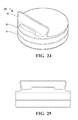
- FIG. 24 is a perspective view of a positioning apparatus according to a second embodiment.
- FIG. 25 is a front view of a positioning apparatus according to the second embodiment.
- FIG. 26 is a perspective view of a positioning system according to the second embodiment.
- FIG. 27 is a front view of the positioning system according to the second embodiment.
- FIG. 28 is a side view of the positioning system according to the second embodiment.
- FIG. 1 illustrates a positioning apparatus according to a first embodiment.
- the positioning apparatus may be adapted to rotate an electronic device in two axes, while further being able to have an angle between the two rotation axes be set by the user.
- the positioning apparatus may be adapted to support a smart phone, as seen in the positioning system illustration of FIG. 2 .
- a positioning apparatus 10 is adapted to be driven in a plurality of axes by an electronic device mounted thereon.
- the electronic device may be a smart phone in some embodiments.
- the electronic device may be a tablet computer in other embodiments.
- the positioning apparatus may be able to position the device, which may include a camera, such that the camera is able to take pictures while tracking a moving object, for example.
- the electronic device/camera is able to send positioning command signals to the positioning device such that the camera is able to take images in a variety of positions.
- the electronic device/camera may be able to receive commands at an input port via a cell phone signal or other wireless transmission mode, which then results in the electronic device/camera commanding the positioning apparatus to alter the orientation of the electronic device/camera.
- the electronic device/camera may transmit images to a remote device, such as another smart phone, allowing the user of the remote device to observe the images being taken by the first device in real time. The user of the remote device may then be able to command the positioning apparatus, allowing for control and tracking of the positioning apparatus and first device by the second device.
- the positioning device is adapted to receive position commands from the electronic device, which may be a smart phone, and to respond by moving to a commanded orientation.
- the positioning device is self-reliant in that it has power, electromechanical drivers, and control electronics (local controller) such that it may move to the commanded orientation based upon simple commands coming from the smart phone.
- the smart phone is mounted to the positioning device such that an electrical connector on the smart phone forms part or all of the mounting interface of the smart phone to the positioning device.
- the positioning apparatus 10 has a lower base 11 which is adapted to reside on a fixed object, such as a table top or the ground.
- the lower rotating unit 12 is adapted to rotate relative to the lower base 11 .
- the lower rotating unit 12 may be movably attached to the lower base 11 such that when the proper commands are sent to the apparatus 10 the lower rotating unit 12 may move as commanded.
- the positioning apparatus 10 has been placed on a horizontal surface, the lower rotating unit rotates around a vertical axis. With the rotation of the lower rotating unit 12 , the entire apparatus 10 , other than the lower base 11 , also rotates in conjunction with the lower rotating unit 12 .
- a second rotating portion allows for rotation around another axis.
- the second axis is coaxial to the first, vertical axis of the lower rotating unit.
- the second rotating portion may have an upper base 13 and an upper rotating unit 14 adapted to rotate relative to the upper base 13 .
- the upper base 13 is rotatably attached to the lower rotating unit at a junction 25 between the two portions.
- the angle between the upper base 13 and the lower rotating unit 12 may be set by hand by the user.
- the junction may be of sufficient friction that the pieces may be set at any relative position and retain their configuration.
- FIG. 6 illustrates the top of the upper rotating unit 14 and its adaptation to receive an electronic device, such as a smart phone.
- a device well 16 on the top of the upper rotating unit 14 allows for the attachment of the electronic unit to the positioning apparatus 10 .
- a device boot 18 or holding element may be adapted to fit a particular device, or type of device, such that the device boot 18 enhances the attachment of the electronic device to the upper rotating unit 14 .
- the device boot 18 may be of a rubberized material, or other resilient material, such that the electronic device is well gripped by the device boot 18 .
- the device boot 18 may be removable and replaceable such that a device boot sized to receive a chosen electronic device is used.
- a device connector 17 may reside within the bottom of the device well 16 .
- the device connector 17 may be a thirty-pin connector in some embodiments.
- the attachment of the electronic device to the device connector 17 may couple the electronic device to the positioning apparatus both electrically and structurally.
- the combination of the physical connection of the electronic device to the device connector 17 , and the friction of the device boot 18 to the electronic device, may lead to a firm attachment of the electronic device to the positioning apparatus 10 , while allowing for easy removal.
- a port 105 may be adapted to receive electronic input into the positioning apparatus 10 .
- the port 105 may be a small USB-type port.
- FIG. 7 illustrates a configuration wherein the upper rotating unit 14 and the upper base 13 have been set at an angle relative to the lower base 11 and the lower rotating unit 12 .
- the two rotation axes are no longer coaxial.
- FIG. 8 illustrates a configuration wherein the upper rotating unit has been set to a greater angle than that seen in FIG. 7 .
- FIG. 9 illustrates a configuration wherein the upper rotating unit has been fully deployed. In this aspect, the rotation axis of the upper rotating unit is perpendicular to the rotation axis of the lower rotating unit. In this fully deployed configuration, a camera, such as a camera on a smart phone, would be rotatable in two axes such that various desired views could be achieved.
- FIGS. 9-12 illustrate a configuration of the positioning apparatus 10 wherein the rotation axis of the lower rotating unit is vertical, and the rotation of the upper rotating unit is horizontal.
- FIGS. 13 and 14 illustrate a positioning system 30 with an electronic device 31 , which may be a smart phone, mounted in a positioning apparatus 10 .
- the electronic device 31 is seen to fit snugly in the device boot 18 .
- the upper rotating unit has not been rotated around the junction 25 .
- FIGS. 15-18 illustrate a positioning system 30 in a fully deployed configuration, wherein the rotation axis of the upper rotating unit is perpendicular to the rotation axis of the lower rotating unit.
- the camera portion of the electronic device 31 may be rotatable to a variety of orientations with the use of the two rotating units.
- the positioning device has electric motors adapted to drive ring gears mounted within the device.
- the base of the device contains a first ring gear driven by an electric motor.
- a second ring gear is driven by a second motor to provide positioning control in a second axis.
- the base of the device may contain batteries which provide electrical power for the positioning control of the device.
- the batteries may be rechargeable and may be recharged by connecting the base to an electrical power source.
- the electrical power may connect via a USB-type connector in the base.
- the electrical power supplied to the base may be used to provide power for, or to recharge, the smart phone mounted in the base as well.
- the batteries of the smart phone may provide the power for the positioning device.
- FIG. 19 illustrates aspects of the drive portion of the lower rotating unit.
- a ring gear is mounted within the inner periphery of the lower base 11 .
- the lower rotating unit 12 houses components which allow the lower rotating unit 12 to rotate relative to the lower base 11 , which may remain fixed upon a surface.
- a motor 42 with a worm gear 43 affixed to its output shaft.
- the motor 42 may be a stepper motor in some embodiments.
- the motor may be an 18-degree stepper, and with the full gearing the output angle of the lower rotating unit relative to the lower base unit may be 0.171 degrees.
- control electronics of the system may be adapted to step the stepper motor at even smaller intervals, such that each 18-degree step may be further broken into thirty-two micro-steps.
- a gear train 44 , 45 leads to an interior ring gear 46 affixed to the lower base.
- a battery 40 and a lower electronics 41 are adapted to provide step control and power to the motor 42 such that the lower rotating unit 12 rotates relative to the lower base 11 .
- electrical power may be delivered via the port in the lower base 11 .
- a rotary sliding contact assembly between the lower base 11 and the lower rotating unit 12 is adapted to transfer an electrical connection from the port to the lower electronics 41 .
- electrical power may be delivered from the battery 40 up to the upper electronics via wires within the junction 25 .
- electrical power and signals may be delivered down to the lower electronics 41 from the upper portion via wires within the junction 25 .
- FIG. 21 illustrates a partial view of an exploded illustration of the upper rotating portion.
- the upper base is seen to have an upper base shell 59 to which is affixed to an upper base structure 58 , with an internal ring gear 62 attached therein.
- the upper base shell 59 couples to the junction 25 .
- the upper rotating portion has an upper rotating unit structure 60 and an upper rotating portion top 61 .
- An upper motor 52 is adapted to drive the gear train in response to a signal from an upper electronics affixed within the upper rotating portion.
- a rotating sliding contact assembly 56 , 57 allows for transfer of electrical power and signals from the upper rotating unit 14 to the upper base 13 .
- the sliding contact assemblies allow for the continuous rotation of each of the rotating portions relative to their bases, as may be desired during continuous tracking of an object by a camera.
- the junction may not be adapted to rotate more than from the stowed to the fully deployed configuration, although this may be done in either direction.
- Wires may be used to transfer power and signals from the upper base to the lower rotating unit.
- the rotating portions may house the motor and drive electronics, while the base portions may have ring gears. In this aspect, the motors and drive electronics may drive themselves around the inside of the ring gears.
- a single axis positioner 80 is adapted to rotate an electronic device, such as a tablet computer 84 .
- the positioner 80 may include a recess 81 adapted to receive a tablet computer 84 .
- a base 83 may reside on a surface, and a rotating portion 82 may rotate relative to the base 83 .
- Aspects of the single axis positioner with regard to drive components may be substantially similar to the components described above with regard to other embodiments.
- the tablet computer 84 may act as a driver for the positioner 80 using a wireless technology, such as Bluetooth.
- the multi-axis positioning control allows a camera mounted onto the positioning device to take pictures at multiple orientations around the location at which the positioning device is placed.
- the positioning device may also be able to be controlled in a dynamic sense, in that the rate of change in position (speed) may also be controlled. This may be useful when the camera is used to track a moving object.
- the positioning device contains control electronics which are adapted to position the camera based upon direction and speed inputs for two axes. In some embodiments, three axes may be controlled.
- the smart phone may contain instructions for allowing operation of the system according to a variety of operational modes.
- the system may operate according to a preselected paradigm, such as creating a panoramic image.
- the camera may move from location to location, taking a still image at each position.
- the camera may rotate around a 360-degree range to make a panoramic video from a single location.
- an adaptor may be used to hold a device otherwise not designed to be held in the standard dock.
- preprogrammed operational paradigms may reside within the memory of the smart phone.
- the user may select the paradigm using the smart phone itself.
- the smart phone may be accessible remotely, such as via the Internet. In these aspects, the user may select the operational paradigm remotely.
- the system may be controllable in real time, such as a remote user using a device, such as a computer or another smart phone, to command the camera/positioning device combination to selected orientations in real time.
- a device such as a computer or another smart phone
- the multi-axis positioning assembly 30 may be controlled by a remote driver 70 .
- the remote driver may be linked to the positioning mechanism by a Wi-Fi or cellular network, for example.
- the expanded system using a remote driver may be part of a system that allows for video chat, or of active tracking by the camera in real time. Examples of this expanded system may utilize a personal computer, or a mobile touch device, for example.
- the remote driver may be a laptop or PC.
- Control may be exercised through either a web app (e.g., Chrome, Firefox, or IE) or stand-alone program (e.g., Skype, Google Videos, Facebook Video, or Apple FaceTime).
- Control may also be exercised through mouse gestures or clicks on the video being seen and sent by the positioning base unit.
- Control may also be exercised via a 3D mouse, track ball, touch pad, eye tracking system, or other input device.
- the remote driver may be a mobile touch device. Control may be by way of swiping a finger across the remote driver screen to move the positioning base unit in the desired direction. Control may also be by using the remote driver accelerometers and gyros to send position commands. The positioning unit may mimic the same orientation as the remote driver. In some embodiments, a pinching gesture may be used to control optical or digital zoom of the camera on the positioning unit.
- a driver may be connected in various ways, such as: (1) Expansion Port 1, (2) USB plugged into the side of the positioning unit, (3) the 30-pin connector in the dock, and (4) Expansion Port 2.
- a driver may also be used to preprogram movements and other commands into the onboard peripheral interface controller (PIC), and be disconnected from the positioning unit once programming is complete.
- PIC peripheral interface controller
- the program may then be executed after a duration of time, at a set time, or by way of a trigger signal from an expansion port or the USB port.
- the trigger could also be the rotation of the positioning unit to a set position such as the battery level indicator position.
- the trigger could also be an IR Remote.
- the system may utilize a positioning unit with an electronic device, such as a smart phone, utilized as a driver, which is coupled to a remote driver, such as another smart phone or a tablet computer, which has sensors such as internal gyros, accelerometers, and/or magnetometers.
- a remote driver such as another smart phone or a tablet computer, which has sensors such as internal gyros, accelerometers, and/or magnetometers.
- the positioning unit and the smart phone mounted thereon may be positionally commanded by the movement of the remote driver.
- a system may comprise a positioning unit with a smart phone residing therein.
- the smart phone may include an application adapted to couple to a remote driver.
- the smart phone may also include a camera which may take video images.
- the remote driver may be a tablet computer which is at a remote location. A user may be using the remote driver to view images taken by the smart phone while the smart phone is in the positioning unit.
- the system may be started such that the smart phone is mounted onto the positioning unit.
- the smart phone may have an application running that is adapted to support the system function.
- the smart phone is coupled to a remote driver, which may be a tablet computer.
- the user may hold the tablet computer, which displays images taken by the camera within the smart phone.
- the images may be video images.
- the tablet computer/remote driver may have one or more internal attitude sensing elements (also defined herein as sensors) such as accelerometers, gyros, and other position, attitude, and acceleration sensors.
- the user may pan or tilt the tablet computer.
- the sensors in the tablet computer provide output which includes information on the attitude change of the tablet computer. This information is transmitted to the smart phone in processed or unprocessed form.
- the transmission of this data may take place over a wireless phone network, over the Internet, over a wireless intranet, or in other ways.
- the smart phone receives the information related to the change in attitude of the driver in a form of attitude commands.
- the smart phone functioning as the driver of the positioning unit, then commands the positioning unit to move the smart phone in concert with the tablet. For example, if the tablet has been rotated clockwise (as viewed from above), the smart phone could then also be rotated clockwise by the positioning unit.
- the driver may determine the rates of rotation of the driver as moved by the user. The driver may then send this information to the smart phone. The smart phone may then command the positioning unit to rotate at the same rate and for the same duration as determined by the driver based upon its sensor input. The user then is able to view images on the tablet that simulate the experience of having turned the remote smart phone and positioning unit assembly.
- the positioning unit may be limited to two axes of movement, which may be pan and tilt. In some embodiments, the positioning unit may move the smart phone in three axes.
- the smart phone on the positioning unit may have its own attitude sensors which may provide output that may be used to verify or correlate that the commands given to the positioning unit, based upon the motion of the driver, have been accurately implemented.
- the system may have autonomous tracking modes which allow the images taken by the camera to be analyzed, with data from this analysis being used to provide positioning commands. For example, an object of interest could be selected, and once selected, the camera may track the object of interest.
- the system may be used to implement time-lapse photography or cinematography.
- the system may be programmed to run time-lapse sequences or smooth video sequences.
- the system may be set to go from point A to point B in X amount of time, and then go to further points, and so on.
- Shot frequency may be set for time-lapse usage. Programming the number of degrees to move, which axis, at what speed for each part of the sequence, may all be done within an app on the driver.
- the application residing on the driver may be adapted to teach positions by moving the pan and tilt axis to the specified position for each step of the sequence, and then either setting the amount of time between positions or the speed to go to each position.
- the number of frames to shoot may also be set for time-lapse applications.
- the user may also utilize a remote driver to move the system to each position specified for the sequence. This way the user may easily see exactly what the system will see at each position along the sequence.
- the user may also use a preprogrammed sequence from a saved list or downloaded from the Internet.
- Position programming may also be used for multi parallel time lapse, defined as operating the system to cycle between two or more positions and shoot a frame at each position. The result is multiple time-lapse videos created over the same period of time.
- the app running this could name each frame captured with a location name and image number for that location. Then the images may be sorted and compiled into a video sequence.
- the app could also use image recognition to precisely align the system with the last frame taken.
- the system may facilitate two-way video conferencing, and may utilize tracking.
- two users may each have a viewing screen such as a tablet computer or fixed screen.
- Each user may also have a positioning unit with a device such as a smart phone which is adapted to take video images of the adjacent user during the video call.
- One or each of the imaging units may be adapted to track the adjacent user during the call.
- the system may be used with motion sensors, or other sensors, that trigger a tracking mode.
- the activation of motion sensors may also instigate a call or other action from the smart phone to another number so that a user may know of the triggering by the motion sensor. At that time, the user may be able to control the position of the camera for viewing.
- a system uses the positioning mechanism as described in part above along with a further tracking mechanism adapted to move the base unit along a rail 90 .
- the control of the system may utilize commands which move the base unit to different positions as part of preprogrammed paradigms or in a real-time command mode.
- the control of the positioning mechanism may be controlled by a driver over a long distance.
- the driver may be coupled to the positioning mechanism over the Internet.
- the driver could be connected to the Internet via a wireless Internet signal.
- the positioning mechanism could be connected to the Internet via a wireless connection to the Internet.
- the positioning mechanism could be coupled over a long distance to the driver using a cell phone signal, such as over a 3G or 4G network. The long distance connection may provide control of the positioning mechanism from the driver as well as transmission of the video signal back to the driver.
- control of the positioning mechanism may be done locally.
- the positioning mechanism which may include a video camera mounted thereon, may couple to the driver over a wireless router in some aspects.
- a local hotspot may provide the coupling of the positioning mechanism to the driver.
- the driver may be used to allow for manual tracking of an event from a device mounted upon a positioning unit.
- a video camera may be mounted on a positioning unit.
- the video camera may be part of a smart phone which includes capability to run an application.
- the video camera and positioning unit may be placed upon a solid mounting location, which may allow for imaging with a minimum of jitter.
- the user may have a handheld device such as another smart phone.
- the handheld smart phone may be coupled to the positioning unit mounted smart phone such that the handheld smart phone may display the image taken by the positioning unit mounted smart phone.
- the user may view the image and pan or tilt the handheld unit so that the positioning unit mounted camera tracks according to the desires of the user, which are relayed by rotating the driver.
- the user may see, in real time, that the positioning unit mounted camera has responded to the movement commands.
- This system allows the user to control the camera in the positioning unit, which is not subject to the jitter that the handheld unit may be experiencing.
- the transmission of the image data to the handheld unit which is done to facilitate this functionality, may be of low quality (low resolution) so that bandwidth is not a limiting factor.
- the image data recorded by the camera in the positioning unit may be of high quality (high resolution), and also not subject to jitter as the handheld unit may be.
- the positioning mechanism with the camera/video camera mounted thereon may be under autonomous control.
- the positioning mechanism/camera system may not be under outside control and instead operates autonomously.
- Such aspects may include time-lapse photography applications, for example.
Landscapes
- Engineering & Computer Science (AREA)
- General Engineering & Computer Science (AREA)
- Mechanical Engineering (AREA)
- Signal Processing (AREA)
- Multimedia (AREA)
- Physics & Mathematics (AREA)
- General Physics & Mathematics (AREA)
- Human Computer Interaction (AREA)
- Computer Networks & Wireless Communication (AREA)
- Studio Devices (AREA)
Abstract
Description
Claims (25)
Priority Applications (5)
| Application Number | Priority Date | Filing Date | Title |
|---|---|---|---|
| US15/217,185 US10021286B2 (en) | 2011-11-14 | 2016-07-22 | Positioning apparatus for photographic and video imaging and recording and system utilizing the same |
| US16/029,916 US10791257B2 (en) | 2011-11-14 | 2018-07-09 | Positioning apparatus for photographic and video imaging and recording and system utilizing the same |
| US16/288,417 US10462347B2 (en) | 2011-11-14 | 2019-02-28 | Positioning apparatus for photographic and video imaging and recording and system utilizing the same |
| US17/034,305 US11489995B2 (en) | 2011-11-14 | 2020-09-28 | Positioning apparatus for photographic and video imaging and recording and system utilizing the same |
| US17/976,997 US11962896B2 (en) | 2011-11-14 | 2022-10-31 | Positioning apparatus for photographic and video imaging and recording and system utilizing the same |
Applications Claiming Priority (7)
| Application Number | Priority Date | Filing Date | Title |
|---|---|---|---|
| US201161559151P | 2011-11-14 | 2011-11-14 | |
| US201261500585P | 2012-02-18 | 2012-02-18 | |
| US201261600585P | 2012-02-18 | 2012-02-18 | |
| US201261620360P | 2012-04-04 | 2012-04-04 | |
| US201261665872P | 2012-06-28 | 2012-06-28 | |
| US13/676,128 US9441781B2 (en) | 2011-11-14 | 2012-11-14 | Positioning apparatus for photographic and video imaging and recording and system utilizing same |
| US15/217,185 US10021286B2 (en) | 2011-11-14 | 2016-07-22 | Positioning apparatus for photographic and video imaging and recording and system utilizing the same |
Related Parent Applications (1)
| Application Number | Title | Priority Date | Filing Date |
|---|---|---|---|
| US13/676,128 Continuation US9441781B2 (en) | 2011-11-14 | 2012-11-14 | Positioning apparatus for photographic and video imaging and recording and system utilizing same |
Related Child Applications (1)
| Application Number | Title | Priority Date | Filing Date |
|---|---|---|---|
| US16/029,916 Continuation US10791257B2 (en) | 2011-11-14 | 2018-07-09 | Positioning apparatus for photographic and video imaging and recording and system utilizing the same |
Publications (2)
| Publication Number | Publication Date |
|---|---|
| US20160330363A1 US20160330363A1 (en) | 2016-11-10 |
| US10021286B2 true US10021286B2 (en) | 2018-07-10 |
Family
ID=49042652
Family Applications (2)
| Application Number | Title | Priority Date | Filing Date |
|---|---|---|---|
| US13/676,128 Active 2032-11-15 US9441781B2 (en) | 2011-11-14 | 2012-11-14 | Positioning apparatus for photographic and video imaging and recording and system utilizing same |
| US15/217,185 Active 2033-01-05 US10021286B2 (en) | 2011-11-14 | 2016-07-22 | Positioning apparatus for photographic and video imaging and recording and system utilizing the same |
Family Applications Before (1)
| Application Number | Title | Priority Date | Filing Date |
|---|---|---|---|
| US13/676,128 Active 2032-11-15 US9441781B2 (en) | 2011-11-14 | 2012-11-14 | Positioning apparatus for photographic and video imaging and recording and system utilizing same |
Country Status (1)
| Country | Link |
|---|---|
| US (2) | US9441781B2 (en) |
Cited By (2)
| Publication number | Priority date | Publication date | Assignee | Title |
|---|---|---|---|---|
| US20180316843A1 (en) * | 2011-11-14 | 2018-11-01 | Gopro, Inc. | Positioning Apparatus for Photographic and Video Imaging and Recording and System Utilizing the Same |
| CN110822222A (en) * | 2018-08-10 | 2020-02-21 | 神讯电脑(昆山)有限公司 | Expansion seat |
Families Citing this family (29)
| Publication number | Priority date | Publication date | Assignee | Title |
|---|---|---|---|---|
| US9518821B2 (en) * | 2012-08-02 | 2016-12-13 | Benjamin Malay | Vehicle control system |
| US9769359B2 (en) | 2013-12-16 | 2017-09-19 | Innova Electronics Corporation | Flexible camera device |
| JP6106764B2 (en) * | 2013-12-27 | 2017-04-05 | 富士フイルム株式会社 | Imaging apparatus and time-lapse imaging method |
| US20150207961A1 (en) * | 2014-01-17 | 2015-07-23 | James Albert Gavney, Jr. | Automated dynamic video capturing |
| US11343864B2 (en) * | 2014-04-25 | 2022-05-24 | Lenovo (Singapore) Pte. Ltd. | Device pairing |
| US9810971B2 (en) * | 2015-03-02 | 2017-11-07 | Chi Hoang | Configurable compact motorized dolly |
| DE102015006437B3 (en) * | 2015-05-18 | 2016-08-18 | progenox GmbH | Leveling unit for cameras or sensors |
| KR101586728B1 (en) * | 2015-10-12 | 2016-01-21 | (주)조은세이프 | Method, apparatus and system for monitering remotely utilizing smartphone |
| KR20170064242A (en) * | 2015-12-01 | 2017-06-09 | 삼성전자주식회사 | Method and Electronic Apparatus for Providing Video Call |
| US10554896B2 (en) | 2016-05-04 | 2020-02-04 | Insidemaps, Inc. | Stereoscopic imaging using mobile computing devices having front-facing and rear-facing cameras |
| USD844009S1 (en) * | 2017-01-06 | 2019-03-26 | Samsung Electronics Co., Ltd. | Docking station for portable electronic device |
| US11163289B2 (en) * | 2017-02-24 | 2021-11-02 | Sharp Kabushiki Kaisha | Control device, terminal device, cradle, notification system, control method, and storage medium |
| WO2018177564A1 (en) * | 2017-03-30 | 2018-10-04 | Grau Paniello Sergi | Mounts for mobile devices |
| US10015295B1 (en) * | 2017-05-19 | 2018-07-03 | Conor Penfold | System and method for improving a photographic camera feature on a portable electronic device |
| KR101963449B1 (en) * | 2017-09-20 | 2019-04-01 | 주식회사 쓰리아이 | System and method for generating 360 degree video |
| DE102017217679A1 (en) * | 2017-10-05 | 2019-04-11 | Siemens Aktiengesellschaft | A display system for providing an adaptive fixture display and method |
| USD892129S1 (en) * | 2018-04-02 | 2020-08-04 | PCTEST Engineering Laboratory, Inc. | MIMO OTA holder |
| US11134200B2 (en) * | 2018-04-23 | 2021-09-28 | Johnson Controls Tyco IP Holdings LLP | Two axis pan tilt camera system configured to maintain a level image when wall or ceiling mounted |
| USD904326S1 (en) * | 2018-08-13 | 2020-12-08 | Ugreen Group Limited | Magnetic charger |
| US11356606B2 (en) | 2019-02-26 | 2022-06-07 | Insidemaps, Inc. | Imaging using mobile computing device in communication with wide field of view (FOV) camera |
| USD928700S1 (en) * | 2019-03-22 | 2021-08-24 | Lg Electronics | Docking station for charging vehicle smart key |
| CN110650236B (en) * | 2019-09-26 | 2021-07-06 | 维沃移动通信有限公司 | Rotating bracket, electronic device and information processing method |
| US11412149B1 (en) * | 2019-10-10 | 2022-08-09 | Mehul Gandhi | Autonomous positioning system for in interchangeable camera devices |
| US20210196058A1 (en) * | 2019-12-30 | 2021-07-01 | Mobile Tech, Inc. | Product merchandising systems with modular puck assemblies for mounting and displaying products |
| JP2022066921A (en) * | 2020-10-19 | 2022-05-02 | エスゼット ディージェイアイ テクノロジー カンパニー リミテッド | Supporting mechanism and imaging system |
| USD973755S1 (en) * | 2020-12-03 | 2022-12-27 | Shenzhen LinQiJing Technology Co., Ltd. | Camera |
| US12132994B2 (en) * | 2021-12-17 | 2024-10-29 | Matterport, Inc. | Motor mount for image capture of surrounding environment |
| USD1083874S1 (en) * | 2022-09-21 | 2025-07-15 | Guangzhou Minyuxing Technology Co., Ltd. | Headphone and stand assembly |
| USD1019661S1 (en) * | 2023-10-05 | 2024-03-26 | Pioneer Square Brands, Inc. | Stand for portable electronic device |
Citations (41)
| Publication number | Priority date | Publication date | Assignee | Title |
|---|---|---|---|---|
| US4989466A (en) | 1989-08-02 | 1991-02-05 | Goodman Ronald C | Gyroscopically stabilized sensor positioning system |
| US5550754A (en) | 1994-05-13 | 1996-08-27 | Videoptic Research | Teleconferencing camcorder |
| US5768648A (en) | 1997-09-05 | 1998-06-16 | Roy Isaia | Camera mount for controlled and steady rolling movement |
| US6354750B1 (en) | 1998-05-29 | 2002-03-12 | Panavision, Inc. | Fourth axis camera support system and method |
| US6428470B1 (en) | 1995-09-15 | 2002-08-06 | Pinotage, Llc | Imaging system and components thereof |
| US20020128538A1 (en) | 1995-09-15 | 2002-09-12 | Thompson Robert Lee | Imaging system and components thereof |
| US20030048357A1 (en) | 2001-08-29 | 2003-03-13 | Geovantage, Inc. | Digital imaging system for airborne applications |
| US20030193588A1 (en) | 2002-03-28 | 2003-10-16 | Yuen Siltex Peter | Remote-control battery powered rain resistance self-video capturing camera mounting device |
| US6708943B2 (en) | 2001-03-16 | 2004-03-23 | Silent Witness Enterprises Ltd. | Camera gimbal |
| US6715940B2 (en) | 2002-09-10 | 2004-04-06 | General Electric Company | Rugged miniature pan/tilt dome camera assembly |
| US20040100563A1 (en) | 2002-11-27 | 2004-05-27 | Sezai Sablak | Video tracking system and method |
| US20040257441A1 (en) | 2001-08-29 | 2004-12-23 | Geovantage, Inc. | Digital imaging system for airborne applications |
| US20060239677A1 (en) | 2005-04-26 | 2006-10-26 | Frank Friedrich | Camera Holder for Stand |
| US20060269278A1 (en) | 2004-10-15 | 2006-11-30 | Kenoyer Michael L | Coordinated camera pan tilt mechanism |
| US7249317B1 (en) * | 1999-09-27 | 2007-07-24 | Canon Kabushiki Kaisha | Information processing apparatus, its control method, and storage medium |
| US20070230946A1 (en) | 2006-03-29 | 2007-10-04 | Canon Kabushiki Kaisha | Cradle having panhead function |
| US20070251408A1 (en) | 2006-04-26 | 2007-11-01 | A&C Ltd. | Camera track and dolly system |
| US20080012980A1 (en) | 2006-07-11 | 2008-01-17 | Akira Yamane | Imaging apparatus |
| US20080024594A1 (en) | 2004-05-19 | 2008-01-31 | Ritchey Kurtis J | Panoramic image-based virtual reality/telepresence audio-visual system and method |
| US20090073388A1 (en) | 2004-05-06 | 2009-03-19 | Dumm Mark T | Camera control system and associated pan/tilt head |
| US7646417B2 (en) | 2003-09-04 | 2010-01-12 | Nikon Corporation | Mobile phone equipped with a camera |
| US7658557B2 (en) | 2007-02-20 | 2010-02-09 | Dexin Corporation | Camera device |
| WO2010036780A1 (en) | 2008-09-25 | 2010-04-01 | Coby Electronics Corporation | Docking station with rotation mechanism |
| US20100079101A1 (en) | 2005-04-27 | 2010-04-01 | Sidman Adam D | Handheld or vehicle-mounted platform stabilization system |
| US7802802B2 (en) | 2004-10-12 | 2010-09-28 | Cambotics Inc. | Camera dolly |
| US20110158620A1 (en) * | 2009-12-28 | 2011-06-30 | Canon Kabushiki Kaisha | Lens apparatus |
| US20110228098A1 (en) | 2010-02-10 | 2011-09-22 | Brian Lamb | Automatic motion tracking, event detection and video image capture and tagging |
| WO2011127201A1 (en) | 2010-04-06 | 2011-10-13 | Youbiq Llc | Camera control |
| US20120019664A1 (en) | 2010-07-26 | 2012-01-26 | Canon Kabushiki Kaisha | Control apparatus for auto-tracking camera system and auto-tracking camera system equipped with same |
| US20120044350A1 (en) | 2007-06-29 | 2012-02-23 | Orion Energy Systems, Inc. | Outdoor lighting fixture and camera systems |
| US20120083314A1 (en) * | 2010-09-30 | 2012-04-05 | Ng Hock M | Multimedia Telecommunication Apparatus With Motion Tracking |
| US20120231421A1 (en) | 2006-01-20 | 2012-09-13 | 3M Innovative Properties Company | Digital dentistry |
| US20120313557A1 (en) | 2011-06-10 | 2012-12-13 | Robotzone, Llc | Camera motion control system with variable autonomy |
| US20130033594A1 (en) | 2011-08-03 | 2013-02-07 | Ge-Hitachi Nuclear Energy Americas Llc | System and apparatus for visual inspection of a nuclear vessel |
| US20130163977A1 (en) | 2011-12-23 | 2013-06-27 | Qwest Communications International Inc. | Camera Barrel Mechanism |
| US20130208128A1 (en) | 2010-04-21 | 2013-08-15 | Faro Technologies, Inc. | Method and apparatus for using gestures to control a laser tracker |
| US20130222685A1 (en) | 2010-08-09 | 2013-08-29 | Cambridge Mechatronics Limited | Camera apparatus |
| US20130278755A1 (en) | 2012-03-19 | 2013-10-24 | Google, Inc | Apparatus and Method for Spatially Referencing Images |
| US8605174B2 (en) | 2011-05-20 | 2013-12-10 | Ricoh Company, Ltd. | Apparatus, method, and system of image processing, and recording medium storing image processing control program |
| US20140009561A1 (en) | 2010-11-12 | 2014-01-09 | Crosswing Inc. | Customizable robotic system |
| US20140055618A1 (en) | 2012-08-22 | 2014-02-27 | Atmos Energy Corporation | Remote camera and adapter therefor |
-
2012
- 2012-11-14 US US13/676,128 patent/US9441781B2/en active Active
-
2016
- 2016-07-22 US US15/217,185 patent/US10021286B2/en active Active
Patent Citations (42)
| Publication number | Priority date | Publication date | Assignee | Title |
|---|---|---|---|---|
| US4989466A (en) | 1989-08-02 | 1991-02-05 | Goodman Ronald C | Gyroscopically stabilized sensor positioning system |
| US5550754A (en) | 1994-05-13 | 1996-08-27 | Videoptic Research | Teleconferencing camcorder |
| US6428470B1 (en) | 1995-09-15 | 2002-08-06 | Pinotage, Llc | Imaging system and components thereof |
| US20020128538A1 (en) | 1995-09-15 | 2002-09-12 | Thompson Robert Lee | Imaging system and components thereof |
| US5768648A (en) | 1997-09-05 | 1998-06-16 | Roy Isaia | Camera mount for controlled and steady rolling movement |
| US6354750B1 (en) | 1998-05-29 | 2002-03-12 | Panavision, Inc. | Fourth axis camera support system and method |
| US7249317B1 (en) * | 1999-09-27 | 2007-07-24 | Canon Kabushiki Kaisha | Information processing apparatus, its control method, and storage medium |
| US6708943B2 (en) | 2001-03-16 | 2004-03-23 | Silent Witness Enterprises Ltd. | Camera gimbal |
| US20030048357A1 (en) | 2001-08-29 | 2003-03-13 | Geovantage, Inc. | Digital imaging system for airborne applications |
| US20040257441A1 (en) | 2001-08-29 | 2004-12-23 | Geovantage, Inc. | Digital imaging system for airborne applications |
| US20030193588A1 (en) | 2002-03-28 | 2003-10-16 | Yuen Siltex Peter | Remote-control battery powered rain resistance self-video capturing camera mounting device |
| US6715940B2 (en) | 2002-09-10 | 2004-04-06 | General Electric Company | Rugged miniature pan/tilt dome camera assembly |
| US20040100563A1 (en) | 2002-11-27 | 2004-05-27 | Sezai Sablak | Video tracking system and method |
| US7646417B2 (en) | 2003-09-04 | 2010-01-12 | Nikon Corporation | Mobile phone equipped with a camera |
| US20090073388A1 (en) | 2004-05-06 | 2009-03-19 | Dumm Mark T | Camera control system and associated pan/tilt head |
| US20080024594A1 (en) | 2004-05-19 | 2008-01-31 | Ritchey Kurtis J | Panoramic image-based virtual reality/telepresence audio-visual system and method |
| US7802802B2 (en) | 2004-10-12 | 2010-09-28 | Cambotics Inc. | Camera dolly |
| US20060269278A1 (en) | 2004-10-15 | 2006-11-30 | Kenoyer Michael L | Coordinated camera pan tilt mechanism |
| US20060239677A1 (en) | 2005-04-26 | 2006-10-26 | Frank Friedrich | Camera Holder for Stand |
| US20100079101A1 (en) | 2005-04-27 | 2010-04-01 | Sidman Adam D | Handheld or vehicle-mounted platform stabilization system |
| US20120231421A1 (en) | 2006-01-20 | 2012-09-13 | 3M Innovative Properties Company | Digital dentistry |
| US20070230946A1 (en) | 2006-03-29 | 2007-10-04 | Canon Kabushiki Kaisha | Cradle having panhead function |
| US20070251408A1 (en) | 2006-04-26 | 2007-11-01 | A&C Ltd. | Camera track and dolly system |
| US20080012980A1 (en) | 2006-07-11 | 2008-01-17 | Akira Yamane | Imaging apparatus |
| US7658557B2 (en) | 2007-02-20 | 2010-02-09 | Dexin Corporation | Camera device |
| US20120044350A1 (en) | 2007-06-29 | 2012-02-23 | Orion Energy Systems, Inc. | Outdoor lighting fixture and camera systems |
| WO2010036780A1 (en) | 2008-09-25 | 2010-04-01 | Coby Electronics Corporation | Docking station with rotation mechanism |
| US20110158620A1 (en) * | 2009-12-28 | 2011-06-30 | Canon Kabushiki Kaisha | Lens apparatus |
| US20110228098A1 (en) | 2010-02-10 | 2011-09-22 | Brian Lamb | Automatic motion tracking, event detection and video image capture and tagging |
| WO2011127201A1 (en) | 2010-04-06 | 2011-10-13 | Youbiq Llc | Camera control |
| US20120062691A1 (en) | 2010-04-06 | 2012-03-15 | Gordon Fowler | Camera Control |
| US20130208128A1 (en) | 2010-04-21 | 2013-08-15 | Faro Technologies, Inc. | Method and apparatus for using gestures to control a laser tracker |
| US20120019664A1 (en) | 2010-07-26 | 2012-01-26 | Canon Kabushiki Kaisha | Control apparatus for auto-tracking camera system and auto-tracking camera system equipped with same |
| US20130222685A1 (en) | 2010-08-09 | 2013-08-29 | Cambridge Mechatronics Limited | Camera apparatus |
| US20120083314A1 (en) * | 2010-09-30 | 2012-04-05 | Ng Hock M | Multimedia Telecommunication Apparatus With Motion Tracking |
| US20140009561A1 (en) | 2010-11-12 | 2014-01-09 | Crosswing Inc. | Customizable robotic system |
| US8605174B2 (en) | 2011-05-20 | 2013-12-10 | Ricoh Company, Ltd. | Apparatus, method, and system of image processing, and recording medium storing image processing control program |
| US20120313557A1 (en) | 2011-06-10 | 2012-12-13 | Robotzone, Llc | Camera motion control system with variable autonomy |
| US20130033594A1 (en) | 2011-08-03 | 2013-02-07 | Ge-Hitachi Nuclear Energy Americas Llc | System and apparatus for visual inspection of a nuclear vessel |
| US20130163977A1 (en) | 2011-12-23 | 2013-06-27 | Qwest Communications International Inc. | Camera Barrel Mechanism |
| US20130278755A1 (en) | 2012-03-19 | 2013-10-24 | Google, Inc | Apparatus and Method for Spatially Referencing Images |
| US20140055618A1 (en) | 2012-08-22 | 2014-02-27 | Atmos Energy Corporation | Remote camera and adapter therefor |
Cited By (8)
| Publication number | Priority date | Publication date | Assignee | Title |
|---|---|---|---|---|
| US20180316843A1 (en) * | 2011-11-14 | 2018-11-01 | Gopro, Inc. | Positioning Apparatus for Photographic and Video Imaging and Recording and System Utilizing the Same |
| US20190199909A1 (en) * | 2011-11-14 | 2019-06-27 | Gopro, Inc. | Positioning apparatus for photographic and video imaging and recording and system utilizing the same |
| US10462347B2 (en) * | 2011-11-14 | 2019-10-29 | Gopro, Inc. | Positioning apparatus for photographic and video imaging and recording and system utilizing the same |
| US10791257B2 (en) * | 2011-11-14 | 2020-09-29 | Gopro, Inc. | Positioning apparatus for photographic and video imaging and recording and system utilizing the same |
| US11489995B2 (en) | 2011-11-14 | 2022-11-01 | Gopro, Inc. | Positioning apparatus for photographic and video imaging and recording and system utilizing the same |
| US11962896B2 (en) | 2011-11-14 | 2024-04-16 | Gopro, Inc. | Positioning apparatus for photographic and video imaging and recording and system utilizing the same |
| CN110822222A (en) * | 2018-08-10 | 2020-02-21 | 神讯电脑(昆山)有限公司 | Expansion seat |
| CN110822222B (en) * | 2018-08-10 | 2022-02-15 | 神讯电脑(昆山)有限公司 | Expansion seat |
Also Published As
| Publication number | Publication date |
|---|---|
| US9441781B2 (en) | 2016-09-13 |
| US20160330363A1 (en) | 2016-11-10 |
| US20130229569A1 (en) | 2013-09-05 |
Similar Documents
| Publication | Publication Date | Title |
|---|---|---|
| US10021286B2 (en) | Positioning apparatus for photographic and video imaging and recording and system utilizing the same | |
| US11962896B2 (en) | Positioning apparatus for photographic and video imaging and recording and system utilizing the same | |
| US20140135062A1 (en) | Positioning apparatus for photographic and video imaging and recording and system utilizing same | |
| US9458963B1 (en) | 360-degree gimbal system | |
| TWI539810B (en) | Panoramic scene capturing and browsing mobile device, system and method | |
| US20160381271A1 (en) | Handheld camera stabilizer with integration of smart device | |
| JP5251779B2 (en) | Portable electronic device, control method, program, imaging system | |
| CN106662793A (en) | Gimbal system using a stabilization gimbal | |
| KR20160144414A (en) | Mount that facilitates positioning and orienting a mobile computing device | |
| CN108235702A (en) | A kind of holder, unmanned plane and its control method | |
| US20180054228A1 (en) | Teleoperated electronic device holder | |
| CN108184061A (en) | Hand-held holder with clapping control method, device and hand-held holder | |
| CN109151392B (en) | Shooting monitoring equipment and cradle head system comprising same | |
| CN104349038B (en) | Enable the method and electronic equipment of pan-shot | |
| KR102007390B1 (en) | Gimbal | |
| WO2018223424A1 (en) | System based on tri-axial pan-tilt stable photographing device | |
| CN107690606B (en) | Gimbals, filming equipment and unmanned aerial vehicles | |
| JP2015012550A (en) | Imaging apparatus and imaging system | |
| KR102213073B1 (en) | Multi channel photographing system based on an imgae and controlling method | |
| US20240114232A1 (en) | Photographing device and system, carrier apparatus, control system, and expansion component | |
| WO2022109774A1 (en) | Camera control method, device, and system | |
| CN211698549U (en) | Portable shooting device | |
| KR102285457B1 (en) | Externally installable exercise condition monitoring apparatus using electronic device | |
| CN210578844U (en) | Photographing apparatus | |
| KR100682462B1 (en) | Shooting controller |
Legal Events
| Date | Code | Title | Description |
|---|---|---|---|
| AS | Assignment |
Owner name: MOTRR, LLC, CALIFORNIA Free format text: ASSIGNMENT OF ASSIGNORS INTEREST;ASSIGNOR:BEVIRT, JOEBEN;REEL/FRAME:039235/0260 Effective date: 20121114 Owner name: MOTRR, LLC, CALIFORNIA Free format text: ASSIGNMENT OF ASSIGNORS INTEREST;ASSIGNOR:GUYOT, JOSH;REEL/FRAME:039235/0358 Effective date: 20121114 Owner name: GOPRO, INC., CALIFORNIA Free format text: ASSIGNMENT OF ASSIGNORS INTEREST;ASSIGNOR:MOTRR, LLC;REEL/FRAME:039235/0610 Effective date: 20160513 |
|
| AS | Assignment |
Owner name: JPMORGAN CHASE BANK, N.A., AS ADMINISTRATIVE AGENT, NEW YORK Free format text: SECURITY INTEREST;ASSIGNOR:GOPRO, INC.;REEL/FRAME:040996/0652 Effective date: 20161215 Owner name: JPMORGAN CHASE BANK, N.A., AS ADMINISTRATIVE AGENT Free format text: SECURITY INTEREST;ASSIGNOR:GOPRO, INC.;REEL/FRAME:040996/0652 Effective date: 20161215 |
|
| STCF | Information on status: patent grant |
Free format text: PATENTED CASE |
|
| AS | Assignment |
Owner name: JPMORGAN CHASE BANK, N.A., AS ADMINISTRATIVE AGENT, NEW YORK Free format text: SECURITY INTEREST;ASSIGNOR:GOPRO, INC.;REEL/FRAME:047713/0309 Effective date: 20181203 Owner name: JPMORGAN CHASE BANK, N.A., AS ADMINISTRATIVE AGENT Free format text: SECURITY INTEREST;ASSIGNOR:GOPRO, INC.;REEL/FRAME:047713/0309 Effective date: 20181203 |
|
| AS | Assignment |
Owner name: GOPRO, INC., CALIFORNIA Free format text: RELEASE OF PATENT SECURITY INTEREST;ASSIGNOR:JPMORGAN CHASE BANK, N.A., AS ADMINISTRATIVE AGENT;REEL/FRAME:055106/0434 Effective date: 20210122 |
|
| MAFP | Maintenance fee payment |
Free format text: PAYMENT OF MAINTENANCE FEE, 4TH YEAR, LARGE ENTITY (ORIGINAL EVENT CODE: M1551); ENTITY STATUS OF PATENT OWNER: LARGE ENTITY Year of fee payment: 4 |
|
| AS | Assignment |
Owner name: WELLS FARGO BANK, NATIONAL ASSOCIATION, AS AGENT, CALIFORNIA Free format text: SECURITY INTEREST;ASSIGNOR:GOPRO, INC.;REEL/FRAME:072358/0001 Effective date: 20250804 Owner name: FARALLON CAPITAL MANAGEMENT, L.L.C., AS AGENT, CALIFORNIA Free format text: SECURITY INTEREST;ASSIGNOR:GOPRO, INC.;REEL/FRAME:072340/0676 Effective date: 20250804 |
|
| MAFP | Maintenance fee payment |
Free format text: PAYMENT OF MAINTENANCE FEE, 8TH YEAR, LARGE ENTITY (ORIGINAL EVENT CODE: M1552); ENTITY STATUS OF PATENT OWNER: LARGE ENTITY Year of fee payment: 8 |