US1000364A - Shirt-ironing machine. - Google Patents
Shirt-ironing machine. Download PDFInfo
- Publication number
- US1000364A US1000364A US57109210A US1910571092A US1000364A US 1000364 A US1000364 A US 1000364A US 57109210 A US57109210 A US 57109210A US 1910571092 A US1910571092 A US 1910571092A US 1000364 A US1000364 A US 1000364A
- Authority
- US
- United States
- Prior art keywords
- ironing
- lever
- shoe
- roll
- machine
- Prior art date
- Legal status (The legal status is an assumption and is not a legal conclusion. Google has not performed a legal analysis and makes no representation as to the accuracy of the status listed.)
- Expired - Lifetime
Links
Images

Classifications
-
- D—TEXTILES; PAPER
- D06—TREATMENT OF TEXTILES OR THE LIKE; LAUNDERING; FLEXIBLE MATERIALS NOT OTHERWISE PROVIDED FOR
- D06F—LAUNDERING, DRYING, IRONING, PRESSING OR FOLDING TEXTILE ARTICLES
- D06F65/00—Ironing machines with rollers rotating against curved surfaces
- D06F65/02—Ironing machines with rollers rotating against curved surfaces with one roller only
- D06F65/06—Ironing machines with rollers rotating against curved surfaces with one roller only the bed being urged against the roller by power
Definitions
- This invention relates to a shirt ironing machine and particularly to a construction adapted to iron the bosom of a shirt.
- the invention has for an object to pr0- Vide a novel and improved construction whereby the board carrying the article to be ironed may be adjusted relative to the ironing roll to secure the desired pressure thereon when in Contact with the roll.
- Another object of the invention is to provide a novel and improved construction of treadle operated means for controlling the application of power to the machine.
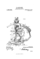
- FIG. 1 is a side elevation of the machine;
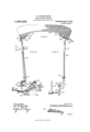
- Fig. 2 is a front elevation thereof partly in section;
- Fig. 3 is a detail side elevation of the lever controlling the adjustment of the ironing board;
- Fig. et is a front elevation of this lever;
- Fig. 5 is a detail side elevation of the support for the ironing board;
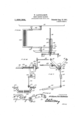
- Fig. 6 is a front elevation of the treadle and power controlling connections;
- Fig. 7, is a side elevation thereof;
- Fig. 8 is a detail plan of these connections;
- anl Fig. 9 is a detail perspective of the sli e.
- the numeral 10 designates the frame of the machine which may be of any desired construction or conguration and is provided at its upper portion with an ironing roll 11 which may be heated in any ordinary manner, for instance' by the connections 12 as shown in Fig. 2.
- the roll 11 is driven by a gear 13 upon the shaft thereof which meshes with a gear4 14 upon the shaft 15 which also carries friction rolls 16 adapted to contact with the base 22 of the ironing board and drive the ironing board 17 which carries the goods to be ironed.
- the gear 14 Specification of Letters Patent.
- the ironing board 17 is supported upon a base 22 as shown in Fig. 2 and this base is carried by an oscillating frame 23 pivotally mounted at 24 upon the slide blocks 25.
- the frame 23 may comprise separate arms which are connected to t-he base 22 for the ironing board by means of screws 26 eX- tended through the plate 27 upon the arms and threaded into the base.
- set screws 28 are mounted in the plate 27 and bear against the base of the ironing board, as shown in Fig. 5.
- the slide blocks 25 are mounted upon segmental ways 29 at the base of the machine and these ways are concentric to the axis of the friction rolls 16.
- the blocks 25 are shifted in the ways by means of a lever 30 adapted to be latched in its adjusted position by means of a sector 31.
- the lever 30 can be sprung laterally a sufficient distance to disengage the shoulder 30X formed thereon adjacent its upper end, from the teeth of the sector.
- the lever 30 is pivoted at 32 and the lower end thereof is bifurcated at 33 and pivotally connected to a frame 34E which is slidingly mounted upon a connecting rod 35.
- This rod is provided with a set collar 36 secured thereto and between this collar and the opposite end of the frame 34, a tension spring 37 is disposed.
- This construction provides for a yielding movement as the-lever is shifted.
- the rod 35 is adjustably connected to la lever 38 by means of a threaded end 39 of the rod and the opposite end 10 of the rod is provided with an angular head to receive a tool to eect a rotation of the rod and its relative adjustment to the lever 38 for the purpose of varying the movement of the slide blocks through this connection.
- the levers 38 areV provided with pivot-ing lugs L11 from which links 42 extend to the slide blocks 25. These blocks are normally retained in position to bring the ironing board in operative contact 4with the heated roll, as shown in Fig. 1, by means of tension springs 43 which are connected at one end to the blocks and at their opposite ends to adjustable screws 44 mounted in fixed parts 45 of the machine. By these means, the proper tension may at all times be maintained upon the blocks and they restored to their initial position.
- treadle connection For the purpose of controlling the power applied to the machine, a treadle connection is provided to coperate with a belt shifter.
- the form of treadle here shown comprises the opposite side frames 46 which are provided with grooves or ways 47 to receive a foot piece 48.
- This foot piece is slidingly adjustable in the side frames to determine the leverage upon the treadle and also to dispose the foot piece in the desired position for use by the operator.
- the foot piece may be held in adjusted position by any desired means, for instance set screws 49.
- the side pieces 46 of the treadle are provided with bearing pintles 50 adapted to be mounted in bearings 51 .upon the side frames of the machine.
- a lug 52 is disposed and adapted to receive the lower end of a connecting rod 53 which is pivotally connected with the short arm 54 of a bell crank lever 55 which is mounted upon a bearing bracket 56, as shown in Figs. 6 and 7.
- the upper end of the bell crank lever 55 is adapted to engage a pin or lug 57 carried by a slide 58 which is mounted for movement upon the shaft 19.
- This slide carries at its outer end the belt shifter arm 60 having the guides 6l to receive the belts which coperate with the tight and loose pulleys 21 and 20, respectively, upon the driving shaft.
- the slide is normally held under tension in its inmost position by means of a spring 62 which surrounds the shaft 19 and bears against the end 63 of the slide and against a fixed point at its opposite end.
- the slide 58 is provided with a stop lug 64 which is adapted to coperate with a retaining lever 65 having ⁇ its handle at the front of the machine and pivotally mounted at 66 for oscillation in a vertical plane.
- the ironing board or table is disposed with its base constantly in contact with the friction driving rolls, the aXis of which is concentric to the pivotal point of the table.
- the pivots of the table may be shifted upon the segmentalways and held in adjusted position.
- the hand lever is provided with a yieldingconnection with a sliding shoe upon which the table is pivoted and this shoe is normally restored to its initial position by a tension spring for that purpose.
- the treadle connection provides means by which the power may be shifted to reverse the direction of drive of the table and the tension spring carried by the belt shifter maintains it in position for driving in one direction while a depression of the treadle will shift the belts to reverse the direction of drive.
- the belt shifter may be held. in an intermediate position by means of the lever engaging the slide at which time both of the belts are held upon the loose pulleys and the machine is inactive.
- an ironing'machine an ironing roll, a coperating ironingjtable, a movable shoe upon which said table is pivoted, an operating lever connected to move said shoe in one direction, and a tension spring to restore said shoe to initial position.
- an ironing machine an ironing roll, a coperating ironing table, a movable shoe upon'which said table is pivoted, an operating lever connected to move said shoe in one direction, a tension spring to restore said shoe to initial position, and means for adjusting the tension of said spring.
- an ironing machine an ironing roll, a coperating ironing table, a movable shoe upon which said table is pivoted, an operating lever connected to move said shoe in one direction, a tension spring to restore said shoe to initial position, a yielding connection between said lever and shoe, and means for retaining said lever in adjusted position.
- an ironingmachine an ironing roll, a coperating ironing table, a shoe upon which said table is pivoted, Va driving roll beneath said table, a segmental way for said shoe disposed concentric to the axis of' said roll, means for adjusting said shoe upon said way in one direction and means for returning said shoe to its original position.
- an ironing machine an ironing roll, a cooperating ironing table, a shoe upon which said table is pivoted, a driving roll beneath said table, a segmental way for said shoe disposed concentric to the axis of said roll, a lever, a link extending from said lever to said shoe, a hand lever, and an adjustable yielding connection between said C .hand lever and said first mentioned lever.
- an iro-ning roll a cooperating ironing table, a shoe upon which said table is pivoted, a driving roll beneath said table, a segmental way for said shoe disposed Vconcentric to the axis of said roll, a lever, a link extending from said lever to said shoe, a hand lever, an adjustable yielding connection between said hand lever and said first mentioned lever, and a restoring spring extending from said shoe to a fixed part.
- an ironing roll an ironing roll, a cooperating ironing table, a shoe upon which said table is pivoted, a driving roll beneath said table, a segmental way for said shoe disposed concentric to the axis of said roll, a lever, a link extending from said lever to said shoe, a hand lever, an adjustable yielding connection between said hand lever and said li'rst mentioned lever, an adjustable screw mounted in a lixed part, and
- an ironing machine an ironing roll, a cooperating ironing table, a shoe upon which said table is pivoted, a driving roll beneath said table, a segmental way for said shoe disposed concentric to the axis of said roll, a lever connected to said shoe, a pivoted hand lever, a frame carried by the lower end of said hand lever, a rod mounted in said frame and connected to said irst mentioned lever, and a tension spring disposed in said frame and bearing against a projection of said rod.
- an ironing machine an ironing roll, a cooperating ironing table, a shoe upon which'said table is pivoted, a driving roll beneath said table, a segmental way for said shoe disposed concentric to the axis of said roll, a lever connected to said shoe, a pivoted hand lever, a frame carried by the lower end of said hand lever, a rod adjustably threaded in said first mentioned lever and extending through said frame, a set collar upon said rod, and a spring extending between said collar and the opposite end of said frame.
Description
W. BARTHOLOMBW.
SHIRT IRONING MACHINE. APPLIOATIQN FILED JULY 8, 1910. I
Patented Aug. 15, 1911 4 SHEETS-SHEET 1.
wLuMBlA 'PLANMIRAPM co.. WASHINGTON. D. c.
W. BARTHOLOMEW.
SHIRT IRONING MACHINE.
APPLIQATIQNl Plum /JULY a, 1910.
Patented Aug. 15,1911.
4 SHEETS-SHEET 2.
(DULUMBIA PLANOURAEH C0., WASHINGTON, D C.
IW. BARTHOLOMEW.
SHIRT IBONING MACHINE.
APPLIoA'rIoN FILED JULY a, 1910.
Patented Aug. 15, '1911.
4 SHEETS-SHEET 4.
idw
llamey WILLIAM BARTHOLOMEW, OF CHICAGO, ILLINOIS, ASSIG-NOR 'IO TROY LAUNDRY MACHINERY COMPANY, LIMITED, OF CHICAGO, ILLINOIS, A CORPORATION OF NEW YORK.
To all 'whom it may concern:
Be it known that I, WILLIAM BARTHoLo- MEW, a citizen of the United States, residing at Chicago, county of Cook, State of Illinois, have invented certain new and useful Improvements in Shirt-Ironing Machines, of which the following is a specification, reference being had therein to the accompanying drawing.
This invention relates to a shirt ironing machine and particularly to a construction adapted to iron the bosom of a shirt.
The invention has for an object to pr0- Vide a novel and improved construction whereby the board carrying the article to be ironed may be adjusted relative to the ironing roll to secure the desired pressure thereon when in Contact with the roll.
Another object of the invention is to provide a novel and improved construction of treadle operated means for controlling the application of power to the machine.
Other and further objects and advantages of the invention will be hereinafter set forth and the novel features thereof defined by the appended claims.
In the drawings-Figure 1 is a side elevation of the machine; Fig. 2 is a front elevation thereof partly in section; Fig. 3 is a detail side elevation of the lever controlling the adjustment of the ironing board; Fig. et is a front elevation of this lever; Fig. 5 is a detail side elevation of the support for the ironing board; Fig. 6 is a front elevation of the treadle and power controlling connections; Fig. 7, is a side elevation thereof; Fig. 8 is a detail plan of these connections; anl Fig. 9 is a detail perspective of the sli e.
Like numerals of reference refer to like parts in the several figures of the drawings. l
The numeral 10 designates the frame of the machine which may be of any desired construction or conguration and is provided at its upper portion with an ironing roll 11 which may be heated in any ordinary manner, for instance' by the connections 12 as shown in Fig. 2. The roll 11 is driven by a gear 13 upon the shaft thereof which meshes with a gear4 14 upon the shaft 15 which also carries friction rolls 16 adapted to contact with the base 22 of the ironing board and drive the ironing board 17 which carries the goods to be ironed. The gear 14 Specification of Letters Patent.
Application led July 8, 1910.
Patented Aug. 15, 1'911.
Serial No. 571,092.
receives power from a pinion 18 disposed on the main driving shaft 19 which is provided with loose pulleys 20 and a tight pulley 21 by which the direction of rotation may be reversed by the usual belt connections with these pulleys.
The ironing board 17 is supported upon a base 22 as shown in Fig. 2 and this base is carried by an oscillating frame 23 pivotally mounted at 24 upon the slide blocks 25. The frame 23 may comprise separate arms which are connected to t-he base 22 for the ironing board by means of screws 26 eX- tended through the plate 27 upon the arms and threaded into the base. -For the purpose of adjusting the ironing board to compensate for any unevenness, set screws 28 are mounted in the plate 27 and bear against the base of the ironing board, as shown in Fig. 5.
The slide blocks 25 are mounted upon segmental ways 29 at the base of the machine and these ways are concentric to the axis of the friction rolls 16. The blocks 25 are shifted in the ways by means of a lever 30 adapted to be latched in its adjusted position by means of a sector 31. The lever 30 can be sprung laterally a sufficient distance to disengage the shoulder 30X formed thereon adjacent its upper end, from the teeth of the sector. The lever 30 is pivoted at 32 and the lower end thereof is bifurcated at 33 and pivotally connected to a frame 34E which is slidingly mounted upon a connecting rod 35. This rod is provided with a set collar 36 secured thereto and between this collar and the opposite end of the frame 34, a tension spring 37 is disposed. This construction provides for a yielding movement as the-lever is shifted. The rod 35 is adjustably connected to la lever 38 by means of a threaded end 39 of the rod and the opposite end 10 of the rod is provided with an angular head to receive a tool to eect a rotation of the rod and its relative adjustment to the lever 38 for the purpose of varying the movement of the slide blocks through this connection. The levers 38 areV provided with pivot-ing lugs L11 from which links 42 extend to the slide blocks 25. These blocks are normally retained in position to bring the ironing board in operative contact 4with the heated roll, as shown in Fig. 1, by means of tension springs 43 which are connected at one end to the blocks and at their opposite ends to adjustable screws 44 mounted in fixed parts 45 of the machine. By these means, the proper tension may at all times be maintained upon the blocks and they restored to their initial position. y
For the purpose of controlling the power applied to the machine, a treadle connection is provided to coperate with a belt shifter. The form of treadle here shown comprises the opposite side frames 46 which are provided with grooves or ways 47 to receive a foot piece 48. This foot piece is slidingly adjustable in the side frames to determine the leverage upon the treadle and also to dispose the foot piece in the desired position for use by the operator. The foot piece may be held in adjusted position by any desired means, for instance set screws 49. The side pieces 46 of the treadle are provided with bearing pintles 50 adapted to be mounted in bearings 51 .upon the side frames of the machine. At the rear ofv one of the side pieces 46, a lug 52 is disposed and adapted to receive the lower end of a connecting rod 53 which is pivotally connected with the short arm 54 of a bell crank lever 55 which is mounted upon a bearing bracket 56, as shown in Figs. 6 and 7. The upper end of the bell crank lever 55 is adapted to engage a pin or lug 57 carried by a slide 58 which is mounted for movement upon the shaft 19. This slide carries at its outer end the belt shifter arm 60 having the guides 6l to receive the belts which coperate with the tight and loose pulleys 21 and 20, respectively, upon the driving shaft. The slide is normally held under tension in its inmost position by means of a spring 62 which surrounds the shaft 19 and bears against the end 63 of the slide and against a fixed point at its opposite end. For the purpose of retaining the belt shifter in position with each of the belts upon a loose pulley, so that the machine may be at rest, the slide 58 is provided with a stop lug 64 which is adapted to coperate with a retaining lever 65 having `its handle at the front of the machine and pivotally mounted at 66 for oscillation in a vertical plane. When the slide is shifted to its inter-V mediate position, placing the spring under tension, the inner end 67 of the lever 65 is adapted to contact with the lug 64 and retain the parts'in this position as long as desired.
In the operation of the invention, the ironing board or table is disposed with its base constantly in contact with the friction driving rolls, the aXis of which is concentric to the pivotal point of the table. For the purpose of increasing or decreasing the pressure of the table against the heated ironing roll, for instance in case of different thicknesses of material, the pivots of the table may be shifted upon the segmentalways and held in adjusted position. For the purpose of this shifting, the hand lever is provided with a yieldingconnection with a sliding shoe upon which the table is pivoted and this shoe is normally restored to its initial position by a tension spring for that purpose. The treadle connection provides means by which the power may be shifted to reverse the direction of drive of the table and the tension spring carried by the belt shifter maintains it in position for driving in one direction while a depression of the treadle will shift the belts to reverse the direction of drive. The belt shifter may be held. in an intermediate position by means of the lever engaging the slide at which time both of the belts are held upon the loose pulleys and the machine is inactive. It will, therefore, be seen that the invention presents a simple, efficient and economically constructed form of shirt ironer in which the most rapid operation is possible and the parts adapted for ready control bythe operator.
Having described my invention and set forth its merits what I claim and desire to secure by Letters Patent isl. In an ironing'machine, an ironing roll, a coperating ironingjtable, a movable shoe upon which said table is pivoted, an operating lever connected to move said shoe in one direction, and a tension spring to restore said shoe to initial position.
2. In an ironing machine, an ironing roll, a coperating ironing table, a movable shoe upon'which said table is pivoted, an operating lever connected to move said shoe in one direction, a tension spring to restore said shoe to initial position, and means for adjusting the tension of said spring.
3. In an ironing machine, an ironing roll, a coperating ironing table, a movable shoe upon which said table is pivoted, an operating lever connected to move said shoe in one direction, a tension spring to restore said shoe to initial position, and a yielding connection between said lever and shoe.l
4. In an ironing machine, an ironing roll, a coperating ironing table, a movable shoe upon which said table is pivoted, an operating lever connected to move said shoe in one direction, a tension spring to restore said shoe to initial position, a yielding connection between said lever and shoe, and means for retaining said lever in adjusted position.
5. In an ironingmachine, an ironing roll, a coperating ironing table, a shoe upon which said table is pivoted, Va driving roll beneath said table, a segmental way for said shoe disposed concentric to the axis of' said roll, means for adjusting said shoe upon said way in one direction and means for returning said shoe to its original position. y 6. In an V.ironing machine, an ironing roll, a coperating ironing table, a shoe upon which said table is pivoted, a driving roll beneath said table, a segmental way for said shoe disposed concentric to the axis of said roll, a lever, a link extending from said lever tosaid shoe, a hand lever, and an adjustable connection between said hand lever and said first mentioned lever.
7. In an ironing machine, an ironing roll, a cooperating ironing table, a shoe upon which said table is pivoted, a driving roll beneath said table, a segmental way for said shoe disposed concentric to the axis of said roll, a lever, a link extending from said lever to said shoe, a hand lever, and an adjustable yielding connection between said C .hand lever and said first mentioned lever.
8. In an ironing machine, an iro-ning roll, a cooperating ironing table, a shoe upon which said table is pivoted, a driving roll beneath said table, a segmental way for said shoe disposed Vconcentric to the axis of said roll, a lever, a link extending from said lever to said shoe, a hand lever, an adjustable yielding connection between said hand lever and said first mentioned lever, and a restoring spring extending from said shoe to a fixed part.
9. In an ironing machine, an ironing roll, a cooperating ironing table, a shoe upon which said table is pivoted, a driving roll beneath said table, a segmental way for said shoe disposed concentric to the axis of said roll, a lever, a link extending from said lever to said shoe, a hand lever, an adjustable yielding connection between said hand lever and said li'rst mentioned lever, an adjustable screw mounted in a lixed part, and
a tension spring connected to said screw and shoe.
10. In an ironing machine, an ironing roll, a cooperating ironing table, a shoe upon which said table is pivoted, a driving roll beneath said table, a segmental way for said shoe disposed concentric to the axis of said roll, a lever connected to said shoe, a pivoted hand lever, a frame carried by the lower end of said hand lever, a rod mounted in said frame and connected to said irst mentioned lever, and a tension spring disposed in said frame and bearing against a projection of said rod.
11. In an ironing machine, an ironing roll, a cooperating ironing table, a shoe upon which'said table is pivoted, a driving roll beneath said table, a segmental way for said shoe disposed concentric to the axis of said roll, a lever connected to said shoe, a pivoted hand lever, a frame carried by the lower end of said hand lever, a rod adjustably threaded in said first mentioned lever and extending through said frame, a set collar upon said rod, and a spring extending between said collar and the opposite end of said frame.
In testimony whereof I aflix my signature in presence of two witnesses.
WILLIAM BARTHOLOMEW.
Witnesses:
WM. KROGMAN, JNO. HOERMANN.
Copies of this patent may be obtained for ve cents each, by addressing the Commissioner of Patents, Washington, D. C.
Priority Applications (1)
| Application Number | Priority Date | Filing Date | Title |
|---|---|---|---|
| US57109210A US1000364A (en) | 1910-07-08 | 1910-07-08 | Shirt-ironing machine. |
Applications Claiming Priority (1)
| Application Number | Priority Date | Filing Date | Title |
|---|---|---|---|
| US57109210A US1000364A (en) | 1910-07-08 | 1910-07-08 | Shirt-ironing machine. |
Publications (1)
| Publication Number | Publication Date |
|---|---|
| US1000364A true US1000364A (en) | 1911-08-15 |
Family
ID=3068690
Family Applications (1)
| Application Number | Title | Priority Date | Filing Date |
|---|---|---|---|
| US57109210A Expired - Lifetime US1000364A (en) | 1910-07-08 | 1910-07-08 | Shirt-ironing machine. |
Country Status (1)
| Country | Link |
|---|---|
| US (1) | US1000364A (en) |
-
1910
- 1910-07-08 US US57109210A patent/US1000364A/en not_active Expired - Lifetime
Similar Documents
| Publication | Publication Date | Title |
|---|---|---|
| US1000364A (en) | Shirt-ironing machine. | |
| US441373A (en) | Ironing-machine | |
| US598233A (en) | Ironing-machine | |
| US941857A (en) | Power-transmitter for sewing-machines. | |
| US626948A (en) | walker | |
| US540334A (en) | Mangle | |
| US999037A (en) | Driving-gear. | |
| US157245A (en) | Improvement in clothes-mangles | |
| US359095A (en) | Ironing-machine | |
| US429076A (en) | Shirt-ironing machine | |
| US1170532A (en) | Ironing-machine. | |
| US1021231A (en) | Cuff-press. | |
| US725414A (en) | Reversing mechanism. | |
| US492752A (en) | sceeaubstadtee | |
| US415094A (en) | Reversing mechanism for ironing-machines | |
| US439454A (en) | Ironing-machine | |
| US802878A (en) | Fleshing-machine. | |
| US689382A (en) | Belt-shifter for embossing-presses. | |
| US508075A (en) | Power-transmitter | |
| US1133749A (en) | Warping-machine. | |
| US761834A (en) | Ironing-machine. | |
| US625973A (en) | Starch ing-machine | |
| US386706A (en) | Neckband-srqner | |
| US433646A (en) | Ironing-machine | |
| US1046936A (en) | Ironing-machine. |