TWM667451U - Manipulator, detection device for detecting physical features of micro-nano element - Google Patents
Manipulator, detection device for detecting physical features of micro-nano element Download PDFInfo
- Publication number
- TWM667451U TWM667451U TW113213127U TW113213127U TWM667451U TW M667451 U TWM667451 U TW M667451U TW 113213127 U TW113213127 U TW 113213127U TW 113213127 U TW113213127 U TW 113213127U TW M667451 U TWM667451 U TW M667451U
- Authority
- TW
- Taiwan
- Prior art keywords
- slide rail
- assembly
- robot arm
- top cover
- cantilever
- Prior art date
Links
Images




Landscapes
- Manipulator (AREA)
- Eye Examination Apparatus (AREA)
Abstract
Description
本揭露係關於一種機械手臂及檢測裝置,尤其係關於提供一種具有機械手臂之檢測裝置並使用其以檢測微奈米元件之物理特徵。 The present disclosure relates to a robot arm and a detection device, and more particularly to providing a detection device having a robot arm and using the robot arm to detect physical characteristics of micro-nano components.
探針常被使用於半導體元件的製造及分析過程中,尤其常被使用於檢測如晶片、晶圓、電晶體、積體電路板、或其他微奈米級電子元件的結構、尺寸、材料特性或可能存在的缺陷。不同的技術領域可能會有不同的檢測需求,例如結構分析或電性測試等;再例如可使用電子束來回掃描待測物之表面,並透過觀察反射光或透射光以檢測待測物之表面特徵,如凹凸起伏之形狀等,從而對待側物進行表面特徵的檢測。隨著科技日漸發展,半導體的應用層面越來越廣泛,對於半導體零件的需求也與日俱增,而半導體的製造過程中又對於精確度的控管尤為要求,因此,探針在半導體產業中顯得格外重要。 Probes are often used in the manufacturing and analysis of semiconductor components, especially in detecting the structure, size, material properties or possible defects of chips, wafers, transistors, integrated circuit boards, or other micro-nano-scale electronic components. Different technical fields may have different detection requirements, such as structural analysis or electrical testing; for example, an electron beam can be used to scan the surface of the object to be tested, and the surface characteristics of the object to be tested, such as the shape of bumps, can be detected by observing the reflected light or transmitted light, so as to detect the surface characteristics of the object to be tested. With the development of technology, the application of semiconductors is becoming more and more extensive, and the demand for semiconductor parts is also increasing. In the semiconductor manufacturing process, precision control is particularly required. Therefore, probes are particularly important in the semiconductor industry.
在習知的檢測技術中,探針通常具有特定長度,且其在安裝至檢測裝置後的長度也會保持一定長度。然而,每個待測物的高度或厚度不同,探針之針尖所需觸碰到的待測物表面之位置也不同,因此探針的長度會直接影響針尖深入至待測物中的距離。若是探針的長度過短,會導 致探針無法充分與待測物的表面接觸;相反地,若探針的長度過長,針尖刺入待測物的表面過深,則容易導致探針及待測物損壞。 In known testing technology, the probe usually has a specific length, and its length will remain at a certain length after being installed in the testing device. However, the height or thickness of each object to be tested is different, and the position of the surface of the object to be tested that the probe tip needs to touch is also different. Therefore, the length of the probe will directly affect the distance that the probe tip penetrates into the object to be tested. If the length of the probe is too short, the probe will not be able to fully contact the surface of the object to be tested; on the contrary, if the length of the probe is too long, the needle tip penetrates too deeply into the surface of the object to be tested, which can easily cause damage to the probe and the object to be tested.
出於同樣理由,用以夾持探針的檢測裝置的可調整性也十分重要。然而,習知針對微奈米元件的檢測裝置往往因轉軸方向或元件連接關係的限制,使得某些特定元件間(例如,夾持探針的元件與機械手臂的懸臂)無法相對活動,此導致檢測裝置不具足夠的可調整性。由於微奈米元件檢測裝置的探針往往會需要做到細微幅度的座標調整,在精度上也極其要求,因此多軸向上的可操作性對於此類設備而言至關重要。除此之外,若探針無法穩定地夾持或容置於檢測裝置中,也會大大影響半導體製程或分析過程的精確程度。 For the same reason, the adjustability of the detection device used to clamp the probe is also very important. However, it is known that the detection device for micro-nano components is often limited by the rotation axis direction or component connection relationship, so that certain specific components (for example, the component holding the probe and the cantilever of the robot arm) cannot move relative to each other, which results in insufficient adjustability of the detection device. Since the probe of the micro-nano component detection device often needs to make fine coordinate adjustments and has extremely high requirements on accuracy, multi-axis operability is crucial for such equipment. In addition, if the probe cannot be stably clamped or accommodated in the detection device, it will also greatly affect the accuracy of the semiconductor process or analysis process.
綜合上述,如何精確地調整探針與待測物之間的距離,且如何在保持探針穩定的情形下增加檢測裝置之可調整性,使其具有更準確的量測結果,係本技術領域中亟待解決的技術問題。 In summary, how to accurately adjust the distance between the probe and the object to be tested, and how to increase the adjustability of the detection device while keeping the probe stable so that it has more accurate measurement results, are technical problems that need to be solved urgently in this technical field.
本揭露主要提供一種用於夾持探針的機械手臂、具有機械手臂的檢測裝置以及檢測微奈米元件之物理特徵的方法。前述機械手臂具備多軸向的調整能力,且擁有良好的夾持穩定性,從而使檢測裝置的操作更加靈活便利,並提升量測結果的準確性。 The present disclosure mainly provides a mechanical arm for clamping a probe, a detection device having the mechanical arm, and a method for detecting the physical characteristics of micro-nano components. The mechanical arm has multi-axial adjustment capabilities and good clamping stability, thereby making the operation of the detection device more flexible and convenient, and improving the accuracy of the measurement results.
在一些實施例當中,本揭露提供一種用於夾持探針的機械手臂,其包含設置於一定位調整底座上之一定位調整組件。該定位調整組件包含一滑軌組合件,其包含一滑軌頂蓋及一彈性元件。該滑軌頂蓋之一滑軌可滑動地容納於一滑軌底座之一滑槽中,而該彈性元件的兩端分別固定至該滑軌底座及該滑軌頂蓋。此外,該機械手臂更包含一手輪組合件、 一連接於該定位調整組件的懸臂件及一具有孔洞之夾持件。該手輪組合件可與該滑軌頂蓋接觸,且該連接件容納於該懸臂件內凹槽內。 In some embodiments, the present disclosure provides a robot arm for clamping a probe, which includes a positioning adjustment assembly disposed on a positioning adjustment base. The positioning adjustment assembly includes a slide rail assembly, which includes a slide rail top cover and an elastic element. A slide rail of the slide rail top cover can be slidably accommodated in a slide groove of a slide rail base, and the two ends of the elastic element are respectively fixed to the slide rail base and the slide rail top cover. In addition, the robot arm further includes a handwheel assembly, a cantilever connected to the positioning adjustment assembly, and a clamping member with a hole. The handwheel assembly can contact the slide rail top cover, and the connecting member is accommodated in a groove in the cantilever.
在一釋例性的實施例中,其中該第一滑軌底座上設置有一第一手輪連接架,該第一手輪連接架中設置有一第一導引件,且該第一手輪組合件之該螺桿可鎖合至該第一導引件之一通孔中。 In an exemplary embodiment, a first handwheel connecting frame is disposed on the first slide rail base, a first guide is disposed in the first handwheel connecting frame, and the screw of the first handwheel assembly can be locked into a through hole of the first guide.
在一釋例性的實施例中,其中該定位調整組件進一步包含:一第二滑軌組合件,其包含連接於該第一滑軌組合件之一第二滑軌連接板;一第二滑軌頂蓋,該第二滑軌頂蓋之一滑槽大致沿一第二方向可滑動地容納於一第二滑軌底座之一滑軌中;以及一第二彈性元件,其兩端分別固定至該第二滑軌底座及該第二滑軌頂蓋;且該機械手臂進一步包含一第二手輪組合件,其具有可與該第二滑軌頂蓋接觸之一螺桿,其中該第二方向大致與該第一方向垂直。 In an exemplary embodiment, the positioning adjustment assembly further comprises: a second slide rail assembly, which comprises a second slide rail connecting plate connected to the first slide rail assembly; a second slide rail top cover, a slide groove of the second slide rail top cover is slidably accommodated in a slide rail of a second slide rail base approximately along a second direction; and a second elastic element, whose two ends are respectively fixed to the second slide rail base and the second slide rail top cover; and the robot arm further comprises a second hand wheel assembly, which has a screw that can contact the second slide rail top cover, wherein the second direction is approximately perpendicular to the first direction.
在一釋例性的實施例中,其中該第二滑軌底座上設置有一第二手輪連接架,該第二手輪連接架中設置有一第二導引件,且該第二手輪組合件之該螺桿可鎖合至該第二導引件之一通孔中。 In an exemplary embodiment, a second handwheel connecting frame is disposed on the second slide rail base, a second guide member is disposed in the second handwheel connecting frame, and the screw of the second handwheel assembly can be locked into a through hole of the second guide member.
在一釋例性的實施例中,其中該定位調整組件進一步包含:一第三滑軌組合件,其包含連接於該第二滑軌組合件之一第三滑軌頂蓋,該第三滑軌頂蓋之一滑槽沿一第三方向可滑動地容納於一第三滑軌底座之一滑軌中,且該第三滑軌底座設置於該定位調整底座之一側;以及一第三彈性元件,其兩端分別固定至該第三滑軌底座及該第三滑軌頂蓋之間;且該機械手臂進一步包含一第三手輪組合件,其具有可與該第三滑軌頂蓋接觸之一螺桿,其中該第三方向大致與該第一方向及該第二方向垂直。 In an exemplary embodiment, the positioning adjustment assembly further includes: a third slide rail assembly, which includes a third slide rail cover connected to the second slide rail assembly, a slide groove of the third slide rail cover is slidably accommodated in a slide rail of a third slide rail base along a third direction, and the third slide rail base is arranged on one side of the positioning adjustment base; and a third elastic element, whose two ends are respectively fixed between the third slide rail base and the third slide rail cover; and the robot arm further includes a third hand wheel assembly, which has a screw that can contact the third slide rail cover, wherein the third direction is substantially perpendicular to the first direction and the second direction.
在一釋例性的實施例中,其中該第三滑軌底座上設置有一第三手輪連接架,該第三手輪連接架中設置有一第三導引件,且該第三手輪組合件之該螺桿可鎖合至該第三導引件之一通孔中。 In an exemplary embodiment, a third handwheel connecting frame is disposed on the third slide rail base, a third guide is disposed in the third handwheel connecting frame, and the screw of the third handwheel assembly can be locked into a through hole of the third guide.
在一釋例性的實施例中,其中該第一滑軌頂蓋可沿該第一方向相對於該第一滑軌底座移動±10mm。 In an exemplary embodiment, the first slide rail top cover can move ±10 mm relative to the first slide rail base along the first direction.
在一釋例性的實施例中,其中該懸臂件進一步包含一懸臂連接板,且該懸臂件之該端通過該懸臂連接板固定至該定位調整組件。 In an exemplary embodiment, the cantilever member further includes a cantilever connecting plate, and the end of the cantilever member is fixed to the positioning adjustment assembly through the cantilever connecting plate.
在一釋例性的實施例中,其中該連接件之一第一端定位於該懸臂件之該凹槽的內部並與該懸臂件樞接,藉此該連接件可以該第一端為軸相對於該懸臂件在由該第一方向及該第二方向所構成之一第一平面上轉動。 In an exemplary embodiment, a first end of the connecting member is positioned inside the groove of the cantilever member and is pivotally connected to the cantilever member, whereby the connecting member can rotate relative to the cantilever member on a first plane formed by the first direction and the second direction with the first end as an axis.
在一釋例性的實施例中,其中該連接件可在該第一平面上轉動10度。 In an exemplary embodiment, the connector can rotate 10 degrees on the first plane.
在一釋例性的實施例中,其中該懸臂件進一步包含一高度調節旋鈕,其鄰近設置於該連接件之相對於該第一端之一第二端。 In an exemplary embodiment, the cantilever member further includes a height adjustment knob disposed adjacent to a second end of the connecting member opposite to the first end.
在一釋例性的實施例中,其中該機械手臂進一步包含位於該懸臂件與該夾持件之間的一彈性元件,該位於該懸臂件與該夾持件之間的彈性元件兩端分別固定在定位於該懸臂件之一第一錨定件與定位於該夾持件之一第二錨定件上。其中,該第一錨定件與該第二錨定件分別錯位於一相異高度上。 In an exemplary embodiment, the robot further includes an elastic element located between the cantilever and the clamping member, and the two ends of the elastic element located between the cantilever and the clamping member are respectively fixed on a first anchoring member located on the cantilever and a second anchoring member located on the clamping member. The first anchoring member and the second anchoring member are respectively located at different heights.
在一釋例性的實施例中,其中該第二錨定件設置於該夾持件之一凸出部上。此外,該凸出部可以為平坦表面或具有自由曲面或斜面。 In an exemplary embodiment, the second anchor is disposed on a protrusion of the clamp. In addition, the protrusion may be a flat surface or have a free-form surface or an inclined surface.
在一釋例性的實施例中,其中該夾持件之該第一端活動地樞接於該連接件之相對於該第一端之一第二端,藉此該夾持件可相對於該連接件之該第二端在由該第二方向及該第三方向所構成之一第二平面上活動。 In an exemplary embodiment, the first end of the clamping member is movably connected to a second end of the connecting member opposite to the first end, whereby the clamping member can move relative to the second end of the connecting member on a second plane formed by the second direction and the third direction.
在一釋例性的實施例中,其中該夾持件可在該第二平面上轉動±70度。 In an exemplary embodiment, the clamping member can rotate ±70 degrees on the second plane.
在一釋例性的實施例中,其中該夾持件之該孔洞係形成於一第一定位板及一第二定位板之間,且該第一定位板與該第二定位板之間設有一或多個距離調整件。 In an exemplary embodiment, the hole of the clamping member is formed between a first positioning plate and a second positioning plate, and one or more distance adjustment members are provided between the first positioning plate and the second positioning plate.
在一釋例性的實施例中,其中該機械手臂進一步包含設置於該定位調整組件上之一集線夾。 In an exemplary embodiment, the robot arm further includes a cable collection clip disposed on the positioning adjustment assembly.
在一釋例性的實施例中,其中該定位調整底座或該夾持件之該孔洞之一內壁具有磁性。 In an exemplary embodiment, an inner wall of the hole of the positioning and adjustment base or the clamp is magnetic.
在一些實施例當中,本揭露提供一種用於檢測微奈米元件之物理特徵之檢測裝置,其包含一本揭露之機械手臂、容置於該夾持件之該孔洞之間的一探針固持器、以及與該探針固持器之一端相接合的一探針。 In some embodiments, the present disclosure provides a detection device for detecting physical characteristics of micro-nano components, which includes a disclosed robot arm, a probe holder accommodated between the holes of the clamp, and a probe connected to one end of the probe holder.
在一些實施例當中,本揭露提供一種檢測一微奈米元件之物理特徵的方法,其包含將一本揭露之檢測裝置設置於一基底表面上;提供一光源照射到該微奈米元件之表面,從而獲得一光學訊號;以及接收並處理該光學訊號,從而獲得與該微奈米元件之物理特徵相關之資訊。 In some embodiments, the present disclosure provides a method for detecting the physical characteristics of a micro-nano device, which includes placing a detection device disclosed in the disclosure on a substrate surface; providing a light source to illuminate the surface of the micro-nano device to obtain an optical signal; and receiving and processing the optical signal to obtain information related to the physical characteristics of the micro-nano device.
上文已相當廣泛地概述本揭露之技術特徵,俾使下文之本揭露詳細描述得以獲得較佳瞭解。構成本揭露之申請專利範圍標的之其他 技術特徵將描述於下文。本揭露所屬技術領域中具有通常知識者應瞭解,可相當容易地利用下文揭示之概念與特定實施例作為修改或設計其他結構或製程而實現與本揭露相同之目的。本揭露所屬技術領域中具有通常知識者亦應瞭解,這類等效建構無法脫離後附之申請專利範圍所界定之本揭露的精神和範圍。 The above has been a fairly broad overview of the technical features of the present disclosure, so that the detailed description of the present disclosure below can be better understood. Other technical features that constitute the subject matter of the patent application scope of the present disclosure will be described below. Those with ordinary knowledge in the technical field to which the present disclosure belongs should understand that the concepts and specific embodiments disclosed below can be easily used to modify or design other structures or processes to achieve the same purpose as the present disclosure. Those with ordinary knowledge in the technical field to which the present disclosure belongs should also understand that such equivalent constructions cannot deviate from the spirit and scope of the present disclosure as defined by the attached patent application scope.
1:機械手臂 1:Robotic arm
10:定位調整組件 10: Positioning adjustment assembly
11:滑軌組合件 11: Slide rail assembly
11a:第一滑軌組合件 11a: First slide rail assembly
111a:第一滑軌連接板 111a: First slide rail connecting plate
111b:第二滑軌連接板 111b: Second slide rail connecting plate
112a:第一滑軌底座 112a: First slide rail base
1121a:第一手輪連接架 1121a: First handwheel connecting frame
1122a:第一導引件 1122a: First guide member
113a:位移調整組件 113a: Displacement adjustment assembly
114a:第一滑軌頂蓋 114a: Top cover of the first slide rail
1131a:第一鎖固件 1131a: First lock firmware
1132a:第二鎖固件 1132a: Second lock firmware
1133a:第一彈性元件 1133a: first elastic element
1123a:滑軌 1123a: Slide rail
1141a:滑槽 1141a: Chute
1142a:懸臂固定板 1142a: Cantilever fixing plate
11b:第二滑軌組合件 11b: Second slide rail assembly
114b:第二滑軌頂蓋 114b: Second slide rail top cover
112b:第二滑軌底座 112b: Second slide rail base
1121b:第二手輪連接架 1121b: Second hand wheel connecting frame
1122b:第二導引件 1122b: Second guide member
113b:位移調整組件 113b: Displacement adjustment assembly
1131b:第三鎖固件 1131b: Third lock firmware
1132b:第四鎖固件 1132b: The fourth lock firmware
1133b:第二彈性元件 1133b: Second elastic element
1123b:滑軌 1123b: Slide rail
1141b:滑槽 1141b: Chute
11c:第三滑軌組合件 11c: Third slide rail assembly
114c:第三滑軌頂蓋 114c: Third rail top cover
112c:第三滑軌底座 112c: Third rail base
1121c:第三手輪連接架 1121c: Third hand wheel connecting frame
1122c:第三導引件 1122c: Third guide member
113c:位移調整組件 113c: Displacement adjustment assembly
1131c:第五鎖固件 1131c: Fifth lock firmware
1132c:第六鎖固件 1132c: Sixth lock firmware
1133c:第三彈性元件 1133c: The third elastic element
1123c:滑軌 1123c: Slide rail
1141c:滑槽 1141c: chute
12:手輪組合件 12: Handwheel assembly
12a:第一手輪組合件 12a: First handwheel assembly
121a:手輪部 121a: Handwheel part
122a:螺桿 122a: Screw
12b:第二手輪組合件 12b: Second hand wheel assembly
121b:手輪部 121b: Handwheel part
122b:螺桿 122b: screw
12c:第三手輪組合件 12c: Third handwheel assembly
121c:手輪部 121c: Handwheel part
122c:螺桿 122c: screw
13:定位調整底座 13: Position and adjust the base
14:懸臂件 14: Cantilever parts
141:懸臂連接板 141: Cantilever connecting plate
142:凹槽 142: Groove
143:高度調節旋鈕 143: Height adjustment knob
1431:旋鈕部 1431: Knob
1432:螺桿 1432: Screw
144:第一錨定件 144: First anchor
15:連接件 15: Connectors
151:第一端 151: First end
152:第二端 152: Second end
16:夾持件 16: Clamping piece
161:第一端 161: First end
162:第二錨定件 162: Second anchor
163:凸出部 163: protrusion
164:第一定位板 164: First positioning plate
165:第二定位板 165: Second positioning plate
166:距離調整件 166: Distance adjustment piece
17:彈性元件 17: Elastic element
18:集線夾 18: Cable management clip
2:探針固持器 2: Probe holder
3:探針 3: Probe
4:待測物 4: Object to be tested
BS:基底表面 BS: Base surface
R:接收器 R: Receiver
CA:中 CA: Medium
H:孔洞 H: Hole
S:光源 S: Light source
L:光束 L: beam
L':反射光束 L': reflected beam
D:檢測裝置 D: Detection device
圖1所示為根據本揭露之實施例之機械手臂之示意圖。 FIG1 is a schematic diagram of a robotic arm according to an embodiment of the present disclosure.
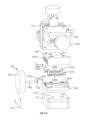
圖2A所示為根據本揭露之實施例之機械手臂之立體分解示意圖一。 FIG2A shows a schematic diagram of a three-dimensional decomposition of a robotic arm according to an embodiment of the present disclosure.
圖2B所示為根據本揭露之實施例之機械手臂之側視圖,其中一滑軌頂蓋處於一中立位置。 FIG. 2B shows a side view of a robot arm according to an embodiment of the present disclosure, wherein a slide rail top cover is in a neutral position.
圖2C所示為根據本揭露之實施例之機械手臂之側視圖,其中一滑軌頂蓋與一手輪組合件接觸且向下位移。 FIG. 2C shows a side view of a robot arm according to an embodiment of the present disclosure, wherein a slide rail top cover contacts a hand wheel assembly and moves downward.
圖2D所示為根據本揭露之實施例之機械手臂之側視圖,其中一滑軌頂蓋與一手輪組合件接觸且向上位移。 FIG. 2D shows a side view of a robot arm according to an embodiment of the present disclosure, wherein a slide rail top cover contacts a hand wheel assembly and moves upward.
圖3A所示為根據本揭露之實施例之機械手臂之立體分解示意圖二。 FIG3A shows a second three-dimensional exploded schematic diagram of a robotic arm according to an embodiment of the present disclosure.
圖3B所示為根據本揭露之實施例之機械手臂之側視圖,其中一滑軌頂蓋處於一中立位置。 FIG. 3B shows a side view of a robot arm according to an embodiment of the present disclosure, wherein a slide rail top cover is in a neutral position.
圖3C所示為根據本揭露之實施例之機械手臂之側視圖,其中一滑軌頂蓋與一手輪組合件接觸且向右位移。 FIG3C shows a side view of a robot arm according to an embodiment of the present disclosure, wherein a slide rail top cover contacts a hand wheel assembly and moves to the right.
圖3D所示為根據本揭露之實施例之機械手臂之側視圖,其中一滑軌頂蓋與一手輪組合件接觸且向左位移。 FIG3D shows a side view of a robot arm according to an embodiment of the present disclosure, wherein a slide rail top cover contacts a hand wheel assembly and moves to the left.
圖4A所示為根據本揭露之實施例之機械手臂之立體分解示意圖三。 FIG4A is a schematic diagram of a three-dimensional decomposition of a robotic arm according to an embodiment of the present disclosure.
圖4B所示為根據本揭露之實施例之機械手臂之側視圖,其中一滑軌頂蓋處於一中立位置。 FIG. 4B shows a side view of a robot arm according to an embodiment of the present disclosure, wherein a slide rail top cover is in a neutral position.
圖4C所示為根據本揭露之實施例之機械手臂之側視圖,其中一滑軌頂蓋與一手輪組合件接觸且向右位移。 FIG. 4C shows a side view of a robot arm according to an embodiment of the present disclosure, wherein a slide rail top cover contacts a hand wheel assembly and moves to the right.
圖4D所示為根據本揭露之實施例之機械手臂之側視圖,其中一滑軌頂蓋與一手輪組合件接觸且向左位移。 FIG. 4D shows a side view of a robot arm according to an embodiment of the present disclosure, wherein a slide rail top cover contacts a hand wheel assembly and moves to the left.
圖5A所示為根據本揭露之實施例之機械手臂之側視圖,其中一連接件容納於一懸臂件之凹槽中。 FIG. 5A shows a side view of a robot arm according to an embodiment of the present disclosure, wherein a connecting member is accommodated in a groove of a cantilever member.
圖5B所示為根據本揭露之實施例之機械手臂之側視圖,其中一連接件之一端以逆時針方向旋轉。 FIG. 5B shows a side view of a robot arm according to an embodiment of the present disclosure, wherein one end of a connecting member rotates counterclockwise.
圖6A所示為根據本揭露之實施例之機械手臂之局部放大圖,其中一夾持件處於一中立位置。 FIG6A shows a partial enlarged view of a robot arm according to an embodiment of the present disclosure, wherein a clamping member is in a neutral position.
圖6B所示為根據本揭露之實施例之機械手臂之局部放大圖,其中一夾持件以順時針方向旋轉。 FIG6B shows a partial enlarged view of a robot arm according to an embodiment of the present disclosure, wherein a clamping member rotates in a clockwise direction.
圖6C所示為根據本揭露之實施例之機械手臂之局部放大圖,其中一夾持件之第一定位板與第二定位板分離。 FIG6C is a partial enlarged view of a robot arm according to an embodiment of the present disclosure, in which the first positioning plate of a clamping member is separated from the second positioning plate.
圖7展示本揭露具有上述實施例之機械手臂之檢測裝置之示意圖。 FIG7 shows a schematic diagram of a detection device of the present disclosure having a robotic arm of the above-mentioned embodiment.
圖8展示本揭露上述實施例之檢測裝置於檢測過程中之示意圖。 FIG8 is a schematic diagram showing the detection device of the above-mentioned embodiment of the present disclosure during the detection process.
為了方便描述,本文中使用空間相對術語(諸如「下面」、「下方」、「下」、「上方」、「上」、「上面」及其類似者)來描述一元件或構件與另一(些)元件或構件之關係,如圖中所繪示。除圖中所描繪之定向之外,空間相對術語亦意欲涵蓋裝置在使用或操作中之不同定向。此 外,本文中亦使用「X軸」、「Y軸」及「Z軸」等相對方向術語描述一元件或構件與另一(些)一元件或構件之關係,應理解該等術語旨在示例而非限制,元件或構件可依其他方式定向(旋轉90度或依其他定向),且亦可據此解譯本文中所使用之空間相對描述詞。 For ease of description, spatially relative terms (such as "below", "below", "down", "above", "upper", "above" and the like) are used herein to describe the relationship between one element or component and another (some) element or component, as shown in the figure. In addition to the orientation depicted in the figure, spatially relative terms are also intended to cover different orientations of the device during use or operation. In addition, relative direction terms such as "X-axis", "Y-axis" and "Z-axis" are also used herein to describe the relationship between one element or component and another (some) element or component. It should be understood that these terms are intended to be illustrative rather than limiting. Elements or components can be oriented in other ways (rotated 90 degrees or in other orientations), and the spatially relative descriptors used herein can also be interpreted accordingly.
本揭露所屬技術領域中具有通常知識者應瞭解,為了簡單且清楚繪示圖中之元件,本揭露之圖式未必按實際比例繪製圖中元件。舉例而言,圖中之一些元件之尺寸可相對於其他元件被誇大以幫助對本技術之各種態樣之理解。 Those with ordinary knowledge in the art to which this disclosure belongs should understand that in order to simply and clearly illustrate the elements in the figures, the figures of this disclosure may not necessarily draw the elements in the figures according to the actual scale. For example, the size of some elements in the figures may be exaggerated relative to other elements to help understand various aspects of this technology.
如本文中所使用,術語「大致」、「實質上」、「實質的」及「實質地」等用以描述及考慮微小之變化。當與事件或情形結合使用時,該等術語可意指事件或情形明確發生之情況以及事件或情形極近似於發生之情況。 As used herein, the terms "substantially", "substantial", "substantial" and "substantially" are used to describe and take into account minor variations. When used in conjunction with an event or circumstance, these terms may refer to both situations where the event or circumstance definitely occurred and situations where the event or circumstance closely approximates to occurring.
圖1所示為根據本揭露之實施例之機械手臂之示意圖。機械手臂1包括一定位調整組件10,其包含至少一個滑軌組合件11,且該定位調整組件10連接至一定位調整底座13。在本揭露的一些實施例中,滑軌組合件11可包含第一滑軌組合件11a、第二滑軌組合件11b以及第三滑軌組合件11c。在本揭露的一些實施例中,第一手輪組合件12a可以與第一滑軌組合件11a相互配合,從而以使懸臂件14能夠沿X軸方向進行移動;第二手輪組合件12b可以與第二滑軌組合件11b相互配合,使懸臂件14沿Y軸方向移動;而第三手輪組合件12c則可以與第三滑軌組合件11c相互配合,使懸臂件14能夠沿Z軸方向進行移動。
FIG1 is a schematic diagram of a robot arm according to an embodiment of the present disclosure. The
在一些實施例中,手輪組合件12的位置可以根據使用者的偏好進行不同的配置。例如,在圖1中所示的第三手輪組合件12c被設置
於定位調整組件10的左側,但可以根據使用者的需求(例如,使用者的慣用手不同)將第三手輪組合件12c設置在定位調整組件10的右側。此外,手輪組合件12的手輪部(例如,圖2A中所示之第一手輪件12a的手輪部121a)可以附有刻紋或刻度(未圖示),以便於使用者進行轉動操作。
In some embodiments, the position of the
懸臂件14的一端通過懸臂連接板141與定位調整組件10連接。如圖1所示,懸臂連接板141上設有多個孔洞,可以使用螺絲或其他鎖固方式,將懸臂連接板141固定在定位調整組件10上。如此一來,懸臂件14能夠藉由懸臂連接板141可拆卸地設置在定位調整組件10的一側,並允許使用者根據實際使用需求快速替換機械手臂1的懸臂件14。在一些實施例中,懸臂件14也可以與懸臂連接板141一體成形。在其他實施例中,可以在懸臂連接板141的表面設置多個懸臂件14,該等懸臂件14可分別設置不同位置且具有相同或相異長度,藉此,多個懸臂件14可分別配置一或多個夾持件16。
One end of the
懸臂件14內設置有一凹槽142,且凹槽142的內部可容納一連接件15。連接件15的一端樞接於凹槽142內部,另一端則經構形以與夾持件16相接。此外,夾持件16設有孔洞H,其可容納一探針固持器2或其他部件,而探針固持器2可進而用於固持探針3等各類工具(參考圖7)。在一些實施例中,孔洞H的內徑表面的特定區域上可以設置磁性材料或仿形限位材料,以使容納於孔洞H中的元件更加穩定。藉此,使用者可以通過操作機械手臂1來調整探針3的位置,從而檢測待測物(如微奈米元件)的物理特徵。固持器2的投影面積可以在懸臂件14內,且在其他實施例中,夾持件16的數量可為複數個,且位在懸臂件14的投影面積外。該等夾持件16用於拘留至少一探針3、探針陣列、至少一探針卡或其組合。
A
以下說明本揭露之機械手臂1如何通過各個手輪組合件12與對應的滑軌組合件11之間的相互配合以使懸臂件14沿X軸、Y軸及Z軸方向進行位移。
The following describes how the
請參考圖2A,其展示根據本揭露之實施例之機械手臂之立體分解示意圖。第一滑軌組合件11a的第一滑軌連接板111a通過第二滑軌連接板111b連接至第二滑軌組合件11b,而第一滑軌底座112a則進一步鎖固在第一滑軌連接板111a上,從而使第一滑軌底座112a與第二滑軌組合件11b、第三滑軌組合件11c及定位調整底座13的所形成的整體連接。第一滑軌底座112a上可設置有第一手輪連接架1121a,且第一手輪連接架1121a中配設有第一導引件1122a。第一手輪連接架1121a可透過鎖合等方式固定在第一滑軌底座112a上,也可與第一滑軌底座112a一體成形。如此一來,第一手輪組合件12a的螺桿122a可藉由穿過第一導引件1122a的通孔以連接至第一手輪連接架1121a,並透過旋轉鎖合以與第一手輪連接架1121a相對移動。
Please refer to FIG. 2A, which shows a three-dimensional exploded schematic diagram of a robot arm according to an embodiment of the present disclosure. The first slide
具體而言,第一手輪組合件12a的螺桿122a上刻有外螺紋(未圖式),而第一導引件1122a中的通孔則設有與螺桿122a外螺紋相對應的內螺紋(未圖式)。因此,當使用者轉動第一手輪組合件12a的手輪部121a時,螺桿122a會隨之旋轉,使得螺桿122a上的外螺紋與第一導引件1122a中通孔的內螺紋相互鎖合。藉由這種方式,可以通過旋轉來鎖合第一手輪組合件12a,使其能夠相對於第一滑軌組合件11a的第一手輪連接架1121a進行移動。
Specifically, the
在一些實施例中,第一滑軌組合件11a可以不包含第一手輪連接架1121a,而直接在第一滑軌組合件11a的表面設置第一導引件
1122a。如此一來,第一手輪組合件12a能夠直接旋轉鎖合進設置在第一滑軌組合件11a表面的第一導引件1122a的通孔中。
In some embodiments, the first
第一滑軌組合件11a進一步包含至少一組位移調整組件113a(圖中示出兩組)及第一滑軌頂蓋114a。每組位移調整組件113a包含連接至第一滑軌底座112a的第一鎖固件1131a、連接至第一滑軌頂蓋114a的第二鎖固件1132a以及配置於第一鎖固件1131a第二鎖固件1132a之間的第一彈性元件1133a。第一彈性元件1133a的一端套設在第一鎖固件1131a上,並藉此固定在第一滑軌底座112a上;而第一彈性元件1133a的另一端則套設在第二鎖固件1132a上,並藉此固定於第一滑軌頂蓋114a上。第一滑軌底座112a上的滑軌1123a具有與第一滑軌頂蓋114a中的滑槽1141a相對應的外部輪廓,以供滑軌1123a於滑槽1141a內部進行滑動。如此一來,第一滑軌頂蓋114a便能夠相對於第一滑軌底座112a進行移動。
The first
請同時參考圖1及圖2A至圖2D,圖中展示了第一滑軌組合件11a與第一手輪組合件12a之間相互配合的作動方式,其中,圖2B所示的第一滑軌頂蓋114a處於一中立位置。第一手輪組合件12a通過第一手輪連接架1121a及第一導引件1122a中的通孔與第一滑軌組合件11a相連接,並且第一手輪組合件12a的螺桿122a抵靠在第一滑軌頂蓋114a的表面,在本揭露的一些實施例中,螺桿122a抵靠在滑槽1141a的表面。當使用者旋轉第一手輪組合件12a的手輪部121a時,螺桿122a會隨之轉動並向下移動;此時,由於位於第一彈性元件1133a的一端通過第一鎖固件1131a固定在第一滑軌底座112a及第一滑軌連接板111a上,並且整體連接至第二滑軌組合件11b,而其另一端則通過第二鎖固件1132a固定在第一滑軌頂蓋114a上,因此,當螺桿122a轉動時,第一彈性元件1133a固定在第一滑
軌底座112a上的一端保持不動,而其固定在第一滑軌頂蓋114a上的另一端則會隨第一彈性元件1133a的壓縮及拉伸而移動,從而帶動第一滑軌頂蓋114a相對於第一滑軌底座112a進行位移。
Please refer to FIG. 1 and FIG. 2A to FIG. 2D at the same time, which show the cooperation between the first
詳細而言,如圖2C所示,當使用者順時針旋轉手輪部121a時,螺桿122a會隨之以順時針轉動,並沿X軸方向向下壓抵第一滑軌頂蓋114a。如此一來,第一彈性元件1133a便會被壓縮變形,從而使第一滑軌頂蓋114a相對於第一滑軌底座112a向下移動。相反地,如圖2D所示,當使用者逆時針旋轉手輪部121a時,螺桿122a會隨之以逆時針轉動並向上位移。此時,第一彈性元件1133a因藉由形變所產生的恢復力(彈力)來推動第一滑軌頂蓋114a,使其持續抵靠螺桿122a,並從而帶動第一滑軌頂蓋114a相對於第一滑軌底座112a向上移動。
In detail, as shown in FIG2C , when the user rotates the
如圖2A至圖2D所示,懸臂件14通過懸臂連接板141固定至懸臂固定板1142a,並藉此與第一滑軌組合件11a的第一滑軌頂蓋114a相互連接。因此,當第一滑軌頂蓋114a隨著第一手輪組合件12a向上或向下移動時,機械手臂1的懸臂件14會隨之進行位移,從而實現對懸臂件14沿X軸方向的座標調整。
As shown in Figures 2A to 2D, the
如前所述,轉動第一手輪組合件12a可以調整第一滑軌頂蓋114a的位移,而能透過第一手輪組合件12a調整的最大位移量取決於螺桿122a的長度。具體而言,當螺桿122a的端部向上移動至完全嵌入第一導引件1122a的通孔中時,如當螺桿122a的端部與導引件之底面齊平時,便無法繼續透過轉動第一手輪組合件12a以使第一滑軌頂蓋114a向上位移。類似地,當手輪部121a的底面接觸到第一手輪連接架1121a的頂面時,便無法繼續透過轉動第一手輪組合件12a使第一滑軌頂蓋114a向下位
移。然而,此時仍可透過施加外力而使第一彈性元件1133a進一步壓縮,從而帶動第一滑軌頂蓋114a及懸臂件14持續向下位移。在較佳的實施例中,透過旋轉第一手輪組合件12a,可以使第一滑軌頂蓋114a自中立位置(如圖2B所示)沿X軸移動約±10mm;換句話說,第一滑軌頂蓋114a可自中立位置向上或向下位移達約10mm。
As mentioned above, the displacement of the first slideway
在一些實施例中,機械手臂1可以不包含懸臂連接板141或懸臂固定板1142a中的任一者。換句話說,懸臂件14的一端可以直接連接至第一滑軌頂蓋114a,或者與第一滑軌頂蓋114a一體成形,從而實現與定位調整組件10的連接。
In some embodiments, the
請參閱圖3A,其所示為根據本揭露之實施例之機械手臂之立體分解示意圖二。第二滑軌組合件11b的第二滑軌連接板111b通過第一滑軌連接板111a連接至第一滑軌組合件11a。第二滑軌組合件11b的第二滑軌頂蓋鎖固至第二滑軌連接板111b的底面,而第二滑軌底座112b則鎖固至第三滑軌組合件11c的第三滑軌頂蓋114c。藉此,第二滑軌組合件11b在第一滑軌組合件11a連接的同時,其底面也與第三滑軌組合件11c和定位調整底座13形成的整體連接。
Please refer to FIG. 3A, which is a second three-dimensional exploded schematic diagram of a robot arm according to an embodiment of the present disclosure. The second
與第一滑軌底座112a類似,第二滑軌底座112b上可設置有第二手輪連接架1121b,且第二手輪連接架1121b中配設有第二導引件1122b。第二手輪連接架1121b可透過鎖合等方式固定在第二滑軌底座112b上,也可與第二滑軌底座112b一體成形。藉此,第二手輪組合件12b可穿過第二導引件1122b的通孔以連接至第二手輪連接架1121b,並透過旋轉鎖合以與第二手輪連接架1121b相對移動。此外,第二滑軌組合件11b同樣包含至少一組位移調整組件113b。每組位移調整組件113b包含連
接至第二滑軌底座112b的第三鎖固件1131b、連接至第二滑軌頂蓋114b的第四鎖固件1132b以及第二彈性元件1133b。第二彈性元件1133b的一端套設在第三鎖固件1131b上,並藉此固定在第二滑軌底座112b上;而第二彈性元件1133b的另一端則套設在第四鎖固件1132b上,並藉此固定於第二滑軌頂蓋114b上。類似地,第二滑軌底座112b上的滑軌1123b具有與第二滑軌頂蓋114b中的滑槽1141b相對應的外部輪廓,以供滑軌1123b於滑槽1141b內部進行滑動。如此一來,第二滑軌頂蓋114b便能夠相對於第二滑軌底座112b進行移動。
Similar to the
在一些實施例中,第二滑軌組合件11b可以不包含第二手輪連接架1121b,而直接在第二滑軌組合件11b的表面設置第二導引件1122b。如此一來,第二手輪組合件12b能夠直接旋轉鎖合進設置在第二滑軌組合件11b表面的第二導引件1122b的通孔中。
In some embodiments, the second
圖3B至圖3D展示了第二滑軌組合件11b與第二手輪組合件12b之間相互配合的作動方式,其中,圖3B所示的第二滑軌頂蓋114b處於二中立位置。第二手輪組合件12b通過第二手輪連接架1121b及第二導引件1122b中的通孔與第二滑軌組合件11b相連接,並且第二手輪組合件12b的螺桿122b抵靠在第二滑軌頂蓋114b的表面,在本揭露的一些實施例中,螺桿122b抵靠在滑槽1141b的表面。當使用者旋轉第二手輪組合件12b的手輪部121b時,螺桿122b會隨之轉動並向右移動;此時,由於位於第二彈性元件1133b的一端通過第三鎖固件1131b固定在第二滑軌底座112b及第三滑軌頂蓋114c上,並且連接至第三滑軌組合件11c及定位調整底座13所形成的整體,而其另一端則通過第四鎖固件1132b固定在第二滑軌頂蓋114b及第二滑軌連接板111b上,因此,當螺桿122b轉動時,第二
彈性元件1133b固定在第二滑軌底座112b上的一端保持不動,而其固定在第二滑軌頂蓋114b上的另一端則會隨第二彈性元件1133b的壓縮及拉伸而移動,從而帶動第二滑軌頂蓋114b相對於第二滑軌底座112b進行位移。
FIG. 3B to FIG. 3D illustrate the cooperative actuation between the
詳細而言,如圖3C所示,當使用者順時針旋轉手輪部121b時,螺桿122b會隨之以順時針轉動,並沿Y軸方向向右推動第二滑軌頂蓋114b。如此一來,第二彈性元件1133b便會被壓縮變形,從而使第二滑軌頂蓋114b相對於第二滑軌底座112b向右移動。相反地,如圖3D所示,當使用者逆時針旋轉手輪部121b時,螺桿122b會隨之以逆時針轉動並向左位移。此時,第二彈性元件1133b會藉由形變所產生的恢復力(彈力)來推動第二滑軌頂蓋114b,使其持續抵靠螺桿122b,並從而帶動第二滑軌頂蓋114b相對於第二滑軌底座112b向左移動。
Specifically, as shown in FIG3C , when the user rotates the
如圖3A至圖3D所示,第二滑軌組合件11b透過第二滑軌連接板111b與第一滑軌組合件11a的第一滑軌連接板111a相互連接,並藉此與第一滑軌組合件11a及懸臂件14整體相互連接。因此,當第二滑軌頂蓋114b隨著第二手輪組合件12b向右或向左移動時,第一滑軌組合件11a及機械手臂1的懸臂件14會隨之進行位移,從而實現對懸臂件14沿Y軸方向的座標調整。此外,與第一手輪組合件12a類似,能透過第二手輪組合件12b調整的最大位移量取決於螺桿122b的長度。在較佳的實施例中,透過旋轉第二手輪組合件12b,可以使第二滑軌頂蓋114b自中立位置(如圖3B所示)沿Y軸移動約±10mm;換句話說,第二滑軌頂蓋114b可自中立位置向右或向左位移達約10mm。
As shown in FIG. 3A to FIG. 3D , the second
請參閱圖4A,其所示為根據本揭露之實施例之機械手臂之立體分解示意圖三。第三滑軌組合件11c的第三滑軌頂蓋114c通過第二滑
軌底座112b連接至第二滑軌組合件11b。第三滑軌組合件11c的第三滑軌底座112c鎖固至第三滑軌連接板111c的頂面,而第三滑軌連接板111c則鎖固定位調整底座13。藉此,第三滑軌組合件11c在與第二滑軌組合件11b連接的同時,也通過第三滑軌連接板111c與定位調整底座13連接。在一些實施例中,第三滑軌組合件11c也可以不包含第三滑軌連接板111c,而是直接通過第三滑軌底座112c與定位調整底座13進行連接。
Please refer to FIG. 4A, which is a three-dimensional exploded schematic diagram of the robot arm according to the embodiment of the present disclosure. The third
與第一滑軌組合件11a及第二滑軌組合件11b類似,第三滑軌組合件11c的第三滑軌底座112c上可以設置第三手輪連接架1121c,且第三手輪連接架1121c中配設有第三導引件1122c。第三手輪連接架1121c可透過鎖合等方式固定在第三滑軌底座112c上,也可與第三滑軌底座112c一體成形。藉此,第三手輪組合件12c可以穿過第三導引件1122c的通孔以連接至第三手輪連接架1121c,並透過旋轉鎖合以與第三手輪連接架1121c相對移動。此外,第三滑軌組合件11c同樣包含至少一組位移調整組件113c。每組位移調整組件113c包含連接至第三滑軌底座112c的第五鎖固件1131c、連接至第三滑軌頂蓋114c的第六鎖固件1132c以及第三彈性元件1133c。第三彈性元件1133c的一端套設在第五鎖固件1131c上,並藉此固定在第三滑軌底座112c上;而第三彈性元件1133c的另一端則套設在第六鎖固件1132c上,並藉此固定於第三滑軌頂蓋114c上。類似地,滑軌底座112c上的滑軌1123c具有與滑軌頂蓋114c中的滑槽1141c相對應的外部輪廓,以供滑軌1123c於滑槽1141c內部進行滑動。如此一來,滑軌頂蓋114c便能夠相對於滑軌底座112c進行移動。
Similar to the first
在一些實施例中,第三滑軌組合件11c可以不包含第三手輪連接架1121c,而直接在第三滑軌組合件11c的表面設置第三導引件
1122c。如此一來,第三手輪組合件12c能夠直接旋轉鎖合進設置在第三滑軌組合件11c表面的第三導引件1122c的通孔中。
In some embodiments, the
圖4B至圖4D展示了第三滑軌組合件11c與第三手輪組合件12c之間相互配合的作動方式,其中,圖4B所示的第三滑軌頂蓋114c處於一中立位置。第三手輪組合件12c通過第三手輪連接架1121c及第三導引件1122c中的通孔與第三滑軌組合件11c相連接,並且第三手輪組合件12c的螺桿122c抵靠在滑軌頂蓋114c的表面,在本揭露的一些實施例中,螺桿122c抵靠在滑槽1141c的表面。當使用者旋轉第三手輪組合件12c的手輪部121c時,螺桿122c會隨之轉動並向右移動;此時,由於位於第三彈性元件1133c的一端通過第五鎖固件1131c固定在第三滑軌底座112c及第三滑軌連接板111c上,並且整體連接定位調整底座13,而其另一端則通過第六鎖固件1132c固定在第三滑軌頂蓋114c及第二滑軌底座112b上,因此,當螺桿122c轉動時,第三彈性元件1133c固定在第三滑軌底座112c上的一端保持不動,而其固定在第三滑軌頂蓋114c上的另一端則會隨第三彈性元件1133c的壓縮及拉伸而移動,從而帶動第三滑軌頂蓋114c相對於第三滑軌底座112c進行位移。
FIG. 4B to FIG. 4D illustrate the cooperative actuation between the
詳細而言,如圖4C所示,當使用者順時針旋轉手輪部121c時,螺桿122c會隨之以順時針轉動,並沿Z軸方向向右推動第三滑軌頂蓋114c。如此一來,第三彈性元件1133c便會被壓縮變形,從而使第三滑軌頂蓋114c相對於第三滑軌底座112c向右移動。相反地,如圖3D所示,當使用者逆時針旋轉手輪部121c時,螺桿122c會隨之以逆時針轉動並向左位移。此時,第三彈性元件1133c會藉由形變所產生的恢復力(彈力)來推動第三滑軌頂蓋114c,使其持續抵靠螺桿122c,並從而帶動第
三滑軌頂蓋114c相對於第三滑軌底座112c向左移動。
In detail, as shown in FIG4C , when the user rotates the
如圖4A至圖4D所示,第三滑軌組合件11c透過第三滑軌頂蓋114c與第二滑軌組合件11b的第二滑軌底座112b相互連接,並藉此與第二滑軌組合件11b、第一滑軌組合件11a及懸臂件14(未圖式)整體相互連接。因此,當第三滑軌頂蓋114c隨著第三手輪組合件12c向右或向左移動時,機械手臂1的懸臂件14會隨之進行位移,從而實現對懸臂件14沿Z軸方向的座標調整。此外,與第一手輪組合件12a及第二手輪組合件12b類似,能透過第三手輪組合件12c調整的最大位移量取決於螺桿122c的長度。在較佳的實施例中,透過旋轉第三手輪組合件12c,可以使第三滑軌頂蓋114c自中立位置(如圖4B所示)沿Z軸移動約±10mm;換句話說,第三滑軌頂蓋114c可自中立位置向右或向左位移達約10mm。
As shown in FIG. 4A to FIG. 4D , the
下文說明本揭露的機械手臂1如何通過調整高度調節旋鈕143來實現連接件15在XZ平面上的轉動,並從而調整探針3(參考圖7)針尖16在X軸方向上的座標調整。
The following describes how the
請參考圖1及圖5A至5B,圖5A展示了容納於懸臂件14凹槽142中的連接件15,而圖5B則展示連接件15以其第一端151為軸,且向逆時針方向旋轉的狀態。如圖5A中最佳可見,懸臂件14內設置有凹槽142,該凹槽142的內部可容納連接件15,其中,連接件15的第一端151定位於凹槽142的內部,並通過螺栓及螺帽相互配合以與懸臂件14樞接。
Please refer to Figure 1 and Figures 5A to 5B. Figure 5A shows the connecting
機械手臂1進一步包含夾持件16,該夾持件16的第一端161具有與連接件15的第二端152互補的外部輪廓特徵,並通過鎖合等方式與連接件15的第二端152相接。此外,如圖1所示,夾持件16具有孔洞H,該孔洞可容納檢測裝置D的探針固持器2,而探針固持器2可進一步用以固持
探針3等各類探測工具(請參考圖7)。因此,使用者可以通過操作機械手臂1的夾持件16來調整探針3的位置,從而對待測物(例如微奈米元件)的物理特徵進行檢測。
The
如圖5A及5B所示,懸臂件14進一步包含高度調節旋鈕143,其鄰近設置於連接件15的第二端152。高度調節旋鈕143的結構與手輪組合件12相似,其可包含旋鈕部1431及具有外螺紋(未圖式)的螺桿1432。此外,旋鈕部1431的外表面上可以設有刻紋(未圖式),以便於使用者進行轉動操作。懸臂件14在對應螺桿1432的位置則設有一通孔(未圖式),該通孔內部具有與螺桿1432外螺紋形狀相對應的內螺紋,藉此使高度調節旋鈕143能通過螺桿1432連接至懸臂件14,並且能夠轉動與懸臂件14鎖合。
As shown in FIGS. 5A and 5B , the
機械手臂1進一步包含一彈性元件17,其兩端分別固定至懸臂件14及夾持件16。具體而言,懸臂件14可以在靠近夾持件16一端的頂面上設置第一錨定件144,而夾持件16則可以在遠離懸臂件14一側的頂面上設置第二錨定件162。彈性元件17的兩端可以分別固定在懸臂件14的第一錨定件144及夾持件16的第二錨定件162上。此外,還可以根據設計需求來調整第一錨定件144與第二錨定件162之間的距離,例如,為了配合彈性元件17的彈力係數,可以在夾持件16設計一凸出部163,並將第二錨定件162設置在凸出部163的頂面上,從而縮短第一錨定件144與第二錨定件162之間的距離。
The
在上述實施例的配置中,高度調節旋鈕143鄰近於連接件15的第二端152設置,與其相對的第一端151則與懸臂件14樞接,因此當使用者以順時針方向轉動高度調節旋鈕143的旋鈕部1431時,會帶動螺桿
1432以順時針方向旋轉並向下移動,且使螺桿1432的端部壓抵並推動連接件15。此時,由於連接件的第一端151與懸臂件14樞接,其在X軸及Y軸方向上無法進行移動,因此當螺桿1432向下推動連接件15,會導致連接件15以其第一端151為軸(準確而言係以連接件15樞接至懸臂件14的位置為軸)在XY平面上旋轉。
In the configuration of the above embodiment, the
當使用者以順時針方向轉動旋鈕部1431時,螺桿1432會持續向下壓抵連接件15,並使連接件15的第二端152向下轉動。此時,彈性元件17會被拉伸而產生形變,從而在懸臂件14及夾持件16之間提供恢復力(彈力)。當使用者以逆時針方向轉動高度調節旋鈕143的旋鈕部1431時,螺桿1432則會向上移動,且此時彈性元件17會藉由形變而產生的恢復力(彈力)迫使夾持件16回復至初始位置(如圖5A所示)。
When the user rotates the
如圖5B所示,通過轉動高度調節旋鈕143,可以使連接件15以其第一端151為軸在XY平面上進行轉動,從而調整連接件15與Y軸之間的夾角φ。轉動高度調節旋鈕143所能調整夾角φ的範圍取決於螺桿1432的長度。在較佳的實施例中,夾角φ可介於約0至10度之間。
As shown in FIG. 5B , by turning the
連接件15的第二端152實際上是在XY平面上進行旋轉。由於夾持件16的第一端161與連接件15的第二端152相連,因此當連接件15的第二端152向下旋轉時,會同時帶動夾持件16一起旋轉。然而,當夾持件16夾持探針固持器2並進一步固定探針3時(參考圖7),夾持件16的旋轉所引起的探針3針尖在Y軸方向上的微小位移可以忽略不計。因此,當探針3安裝在探針固持器2上,且探針固持器2被夾持在夾持件16中時,旋轉高度調節旋鈕143可以被視為通過調整連接件15與Y軸之間的夾角φ,從而精確微調探針3針尖在X軸上的座標位置。
The
透過上述實施例的配置,可以通過操作高度調節旋鈕143,使連接件15以其第一端151在XY平面上轉動,從而調整夾持件16在X軸方向上的位移。如此一來,便能實現對探針3針尖座標的精細微調,並提升檢測裝置D在操作上的靈活性以及量測時的精確度。此外,彈性元件17在探針3接觸待測物時,能提供緩衝和減震效果,增強探針3的穩定性,進一步提升檢測裝置D在檢測時的準確度。
Through the configuration of the above embodiment, the
以下說明本揭露之機械手臂如何通過調整夾持件16與連接件15之間的夾角,從而調整探針3在YZ平面上的位置。
The following describes how the robot arm disclosed herein adjusts the position of the
請參考圖5A至圖6B,圖6A展示了夾持件16處於中立位置,而圖6B展示了夾持件16在YZ平面上以順時針方向旋轉的狀態。夾持件16的第一端161藉由螺栓件與螺帽相互配合以與連接件15的第二端152樞接,因此夾持件16可以相對於連接件15的第二端152轉動。當使用者轉動夾持件16時(如圖6B所示),可以調整夾持件16孔洞H的中軸CA與連接件15之間的夾角θ。中軸CA與連接件15的夾角θ可介於約0度至±30度之間,且在較佳的實施例中,夾角θ可介於約0度至±70度之間。換句話說,夾持件16可以相對於連接件15的第二端152分別向左右兩側轉動,使中軸CA與連接件15之間的夾角θ呈現約0度至70度。
Please refer to Figures 5A to 6B, Figure 6A shows the clamping
由於探針3可以通過探針固持器2及夾持件16安裝於機械手臂1上,因此藉由上述實施例的配置,可以通過轉動夾持件16來調整探針3在YZ平面上的座標,從而提升檢測裝置D在檢測過程中的靈活度。
Since the
請參考圖6A及圖6C。圖6C展示呈現分離狀態的第一定位板164及第二定位板165。夾持件16可以包含第一定位板164及第二定位板165,且在圖式所繪製的實施例中,第一定位板164及第二定位板165分別
位於上下兩側。
Please refer to FIG. 6A and FIG. 6C. FIG. 6C shows the
夾持件16的孔洞H可以形成於第一定位板164及第二定位板165之間。具體而言,第一定位板164及第二定位板165可以分別具有彼此對應且大致呈現拱形的半孔,這些半孔的形狀分別對應於探針固持器2的上半輪廓及下半輪廓。當第一定位板164及第二定位板165相互靠近時,這兩個拱形半孔便會形成一個可以容納探針固持器2的完整孔洞H。
The hole H of the clamping
第一定位板164及第二定位板165之間可以進一步設置一或多個距離調整件166。這些距離調整件166用於調整第一定位板164與第二定位板165之間的距離,從而進一步調整孔洞H的大小。如圖6A至圖6C所示,在一些實施例中,距離調整件166可以通過螺栓與螺帽的相互配合而構成。當探針固持器2被安裝於孔洞H中時,使用者可以轉動距離調整件166,以調整第一定位板164及第二定位板165之間的距離,從而鎖緊或鬆開對探針固持器2的夾持。
One or more
在其他實施例中,距離調整件166可以由其他元件所構成,例如彈性元件等。在這種情況下,當使用者拉動第二定位板165使其與第一定位板164分離時,距離調整件166會發生形變,並在第一定位板164及第二定位板165之間提供恢復力(彈力),從而將第二定位板165拉回至初始位置(如圖6A所示)。如此一來,便可以將探針固持器2穩固地夾持於孔洞H之中。
In other embodiments, the
此外,應當瞭解,當探針固持器2之外部輪廓尺寸恰好等於或小於孔洞H的大小時,夾持件16可以在第一定位板164及第二定位板165彼此接觸的情況下,將探針固持器2夾持於其中;而當探針固持器2的外部輪廓尺寸大於孔洞H的大小時,夾持件16則可以在第一定位板164及
第二定位板165彼此不接觸的情況下,將探針固持器2夾持於其中,且此時探針固持器2的至少一部分外部輪廓會貼合孔洞H的周壁。
In addition, it should be understood that when the outer contour size of the
透過上述實施例的配置,可以根據使用者的操作需求更換不同尺寸的探針固持器2,並且能夠將探針固持器2穩固地夾持在夾持件16之中,從而提升了檢測裝置D在檢測過程中的穩定性。
Through the configuration of the above embodiment,
前揭說明將機械手臂1在XY平面上的作動方式(如圖5A至圖5B所展示)及機械手臂1在YZ平面上的作動方式(如圖6A至圖6C所展示)分別進行敘述。然而,應當理解這些不同座標平面上的調整可以同時進行。例如,可在連接件15以其第一端151向下旋轉(如圖5B所示)的同時,使夾持件16相對於連接件15順時針轉動(如6B所示)。
The above description describes the actuation of the
請參閱圖7,其展示配備本揭露的機械手臂1的檢測裝置D。檢測裝置D可用於檢測微奈米元件的物理特徵,其包含機械手臂1、探針固持器2以及探針3。關於機械手臂1的結構及其組件之間的連接關係,已在前文詳細描述,此處不再重複說明。
Please refer to FIG. 7, which shows a detection device D equipped with the
檢測裝置D的探針固持器2可以被容納於機械手臂1的夾持件16的孔洞H中,且探針固持器2的一端可用於接合探針3,從而將探針3固持於其中。在其他的實施例中,探針固持器2可以用於夾持光路校正配件、半導體檢測耗材、積體電路檢測耗材、剛性線材、纜線或電極等其他元件。在實際應用中,探針3可以是微米探針(Micro probe)、奈米探針(Nano probe)、埃米探針(Angstrom probe)或其他用以檢測微奈米級元件的探針。此外,探針3可以是呈一直線狀的針狀物,也可以經折彎處理而具有彎折區段(如圖7所示)。在一些實施例中,至少一個探針固持器2可以被設置為容納於機械手臂1的夾持件16的孔洞H中,且探針固持器2的
一端可用於接合多個間距排列的多個探針陣列於一載體上的探針卡。在其他實施例中,至少一個探針3或探針卡可以被設置於該夾持件的孔洞H的夾持區域內。
The
探針固持器2的一端與探針3相接合,而其相對的另一端則可電性連接至纜線(未圖式),其中,纜線可以是導電線材、通訊線材、資料傳輸線材或其他具有類似功能的線材。因此,在檢測過程中,可以通過纜線來接收和傳遞電訊號。
One end of the
如圖7所示,檢測裝置D的機械手臂1可以進一步包含集線夾18,其設置於定位調整組件10上。在一些實施例中,集線夾18可以設置於定位調整組件10的頂部,即第二滑軌連接板111b上,並通過鎖合等方式固定。該集線夾18經構形以使得纜線可以穿設於其中。在其他實施例中,集線夾18可以設置於機械手臂1的任何位置,例如定位調整組件10的中段或定位調整底座13,並且可以設計為與機械手臂1一體成形。通過上述實施例的配置,可以將纜線(未圖式)整齊地收納在集線夾18中,從而避免其在檢測過程中對檢測裝置D的正常作動造成干擾。
As shown in FIG7 , the
請參考圖8,其展示檢測裝置D在檢測過程中的狀態。在實際應用中,檢測裝置D可以放置於基底表面BS上(請參見圖8)。基底表面BS可以是平坦表面、曲面、不規則的非平坦表面,或者是相對於周圍環境的凹槽或凸起結構。基底表面BS可以由可撓性材料、非撓性材料或其組合構成。另一方面,機械手臂1可以通過調整定位調整底座13來設置於基底表面BS上。定位調整底座13的底面可以是平坦表面、曲面、不規則的非平坦底面,或者是與基底表面BS的形狀特徵互補的表面。在一些實施例中,定位調整底座13可以具有磁性,並能夠吸附至基底表面BS,
從而提高檢測裝置D在檢測過程中的穩定性。
Please refer to Figure 8, which shows the state of the detection device D during the detection process. In practical applications, the detection device D can be placed on the base surface BS (see Figure 8). The base surface BS can be a flat surface, a curved surface, an irregular non-flat surface, or a groove or protrusion structure relative to the surrounding environment. The base surface BS can be composed of a flexible material, an inflexible material or a combination thereof. On the other hand, the
本揭露另提供一種檢測微奈米元件之物理特徵的方法,其包含提供設置於基底表面BS上之具有機械手臂1的檢測裝置D。關於機械手臂1與檢測裝置D的結構及其組件之間的連接關係,已在前文詳細描述,此處不再重複說明。
The present disclosure also provides a method for detecting physical characteristics of micro-nano devices, which includes providing a detection device D having a
在檢測過程中,檢測裝置D被設置於基底表面BS上,用於檢測待測物4的物理特徵。其中,待測物4可以是晶片、晶圓、電晶體、積體電路、或其他微奈米級的電子元件。在檢測過程中,可以提供一或多個可見光或/及不可見光之光源S,以及一或多個訊號收發器,以蒐集有關待測物4之物理特徵。 During the detection process, the detection device D is set on the substrate surface BS to detect the physical characteristics of the object to be tested 4. The object to be tested 4 can be a chip, a wafer, a transistor, an integrated circuit, or other micro-nano electronic components. During the detection process, one or more visible light and/or invisible light sources S and one or more signal transceivers can be provided to collect the physical characteristics of the object to be tested 4.
具體而言,當探針3靠近或接觸待測物4的表面後,光源S可以被操作以發射出光束L,照射到待測物4的表面,並產生反射光束L'。此時,訊號收發器中的接收器R可經組態以接收反射光束L',從而獲得與待測物4相關的光學訊號。接著,接收器R可以通過訊號收發器的發送器,將所接收的光學訊號發送至電子裝置(例如行動終端機、平板電腦、桌上型電腦或其他任何可執行資料處理之電子設備)以進行運算處理,從而獲得與待測物4的物理特徵相關的資訊。
Specifically, when the
此外,儘管在圖8所繪製的實施例中,待測物4與檢測裝置D是放置在同一平面上,但待測物4和檢測裝置D也可以分別放置在兩個彼此分離的表面上,這些不同的表面可以位於不同的高度或位置。 In addition, although in the embodiment shown in FIG. 8 , the object to be tested 4 and the detection device D are placed on the same plane, the object to be tested 4 and the detection device D may also be placed on two separate surfaces, and these different surfaces may be located at different heights or positions.
在一些實施例中,檢測裝置D可以是一種非破壞性的檢測工具,包括但不限於以下設備:原子力顯微鏡(Atomic Force Microscope,AFM)、穿透式電子顯微鏡(Transmission Electron Microscope,TEM)、聚焦離子束顯微鏡(Focused Ion Beam,FIB)、掃描探針顯微鏡(Scanning Probe Microscopy,SPM)、靜電力顯微鏡(Electrostatic Force Microscopy,EFM)、掃描電容顯微鏡(Scanning Capacitance Microscopy,SCM)、掃描離子電導顯微鏡(Scanning Ion conductance Microscope,SICM)。 In some embodiments, the detection device D may be a non-destructive detection tool, including but not limited to the following equipment: Atomic Force Microscope (AFM), Transmission Electron Microscope (TEM), Focused Ion Beam Microscope (FIB), Scanning Probe Microscopy (SPM), Electrostatic Force Microscopy (EFM), Scanning Capacitance Microscopy (SCM), Scanning Ion Conductance Microscope (SICM).
上文已概述若干實施例之特徵,使得熟習技術者可較佳理解本揭露之態樣。熟習技術者應瞭解,其可易於將本揭露用作用於設計或修改其他程序及結構的一基礎以實施相同目的及/或達成本文中所引入之實施例之相同優點。熟習技術者亦應意識到,此等等效構造不應背離本揭露之精神及範疇,且其可對本文作出各種改變、置換及變更。 The features of several embodiments have been summarized above so that those skilled in the art can better understand the state of the present disclosure. Those skilled in the art should understand that they can easily use the present disclosure as a basis for designing or modifying other processes and structures to implement the same purpose and/or achieve the same advantages of the embodiments introduced in this article. Those skilled in the art should also realize that such equivalent structures should not deviate from the spirit and scope of the present disclosure, and that they can make various changes, substitutions and modifications to this article.
1:機械手臂 1:Robotic arm
10:定位調整組件 10: Positioning adjustment assembly
11:滑軌組合件 11: Slide rail assembly
11a:第一滑軌組合件 11a: First slide rail assembly
11b:第二滑軌組合件 11b: Second slide rail assembly
11c:第三滑軌組合件 11c: Third slide rail assembly
12:手輪組合件 12: Handwheel assembly
12a:第一手輪組合件 12a: First handwheel assembly
12b:第二手輪組合件 12b: Second hand wheel assembly
12c:第三手輪組合件 12c: Third handwheel assembly
13:定位調整底座 13: Position and adjust the base
14:懸臂件 14: Cantilever parts
141:懸臂連接板 141: Cantilever connecting plate
142:凹槽 142: Groove
143:高度調節旋鈕 143: Height adjustment knob
15:連接件 15: Connectors
16:夾持件 16: Clamping piece
Claims (19)
Applications Claiming Priority (2)
| Application Number | Priority Date | Filing Date | Title |
|---|---|---|---|
| TW113127519 | 2024-07-23 | ||
| TW113127519 | 2024-07-23 |
Publications (1)
| Publication Number | Publication Date |
|---|---|
| TWM667451U true TWM667451U (en) | 2025-03-01 |
Family
ID=95829032
Family Applications (2)
| Application Number | Title | Priority Date | Filing Date |
|---|---|---|---|
| TW113213127U TWM667451U (en) | 2024-07-23 | 2024-11-29 | Manipulator, detection device for detecting physical features of micro-nano element |
| TW113146386A TWI917081B (en) | 2024-07-23 | 2024-11-29 | Manipulator for holding probes, detection device for detecting physical features of micro-nano devices and method for detecting physical features of micro-nano device |
Family Applications After (1)
| Application Number | Title | Priority Date | Filing Date |
|---|---|---|---|
| TW113146386A TWI917081B (en) | 2024-07-23 | 2024-11-29 | Manipulator for holding probes, detection device for detecting physical features of micro-nano devices and method for detecting physical features of micro-nano device |
Country Status (1)
| Country | Link |
|---|---|
| TW (2) | TWM667451U (en) |
Family Cites Families (6)
| Publication number | Priority date | Publication date | Assignee | Title |
|---|---|---|---|---|
| JP2007147537A (en) | 2005-11-30 | 2007-06-14 | Tokyo Electron Ltd | Probe card transfer assist device and inspection equipment |
| TWI352200B (en) | 2008-01-10 | 2011-11-11 | Chipmos Technologies Inc | Auxiliary disassembling apparatus and jig therein |
| WO2017117257A1 (en) | 2015-12-28 | 2017-07-06 | Celadon Systems, Inc. | Modular rail systems, rail systems, mechanisms, and equipment for devices under test |
| CN209551704U (en) | 2019-01-30 | 2019-10-29 | 厦门市领汇医疗科技有限公司 | A multi-degree-of-freedom manipulator clamping device |
| DE102022109267B4 (en) | 2022-04-14 | 2025-04-10 | Carl Mahr Holding Gmbh | Key unit and holder for a key unit as well as arrangement |
| CN217954668U (en) | 2022-08-12 | 2022-12-02 | 东莞市浪鲸智能自动化装备有限公司 | Lithium battery OCV testing device |
-
2024
- 2024-11-29 TW TW113213127U patent/TWM667451U/en unknown
- 2024-11-29 TW TW113146386A patent/TWI917081B/en active
Also Published As
| Publication number | Publication date |
|---|---|
| TWI917081B (en) | 2026-03-01 |
| TW202604694A (en) | 2026-02-01 |
Similar Documents
| Publication | Publication Date | Title |
|---|---|---|
| US7566884B2 (en) | Specimen holder for electron microscope | |
| US7022976B1 (en) | Dynamically adjustable probe tips | |
| TWI821332B (en) | Inspection jig, and inspection apparatus | |
| CN111198285B (en) | Wafer test probe station | |
| JPH0926458A (en) | Automatic test equipment and dynamic contacts | |
| JPH0776696B2 (en) | Atomic force microscope | |
| KR100841031B1 (en) | Probe exchange method of scanning probe microscope | |
| US20100228374A1 (en) | Semiconductor substrate processing method and apparatus | |
| JP2005037205A (en) | Scanning probe microscope and measuring method thereof | |
| CN113169091B (en) | Actuator for bond head | |
| TWI917081B (en) | Manipulator for holding probes, detection device for detecting physical features of micro-nano devices and method for detecting physical features of micro-nano device | |
| CN223933626U (en) | Robotic arms and detection devices for measuring the physical characteristics of micro and nano components. | |
| JP3252511U (en) | Robotic arm and detection device for detecting physical properties of micro-nano assemblies | |
| JP2011007774A (en) | Alignment adjusting mechanism and measuring instrument | |
| CN110896018B (en) | Scanning electron microscope sample stage with double manipulators | |
| US8402848B2 (en) | Probe holder | |
| CN111077347B (en) | Atomic force microscopy probe clamping device | |
| JP6393542B2 (en) | Contact inspection device | |
| US7034563B1 (en) | Apparatus for measuring of thin dielectric layer properties on semiconductor wafers with contact self aligning electrodes | |
| US20220328341A1 (en) | Wafer chuck for handling a wafer | |
| KR20240115730A (en) | Specimen holder, specimen holder set, and specimen preparation methodmethod | |
| US20260016506A1 (en) | Probe processing apparatus and method for processing probes | |
| TW201535881A (en) | Socket mounting constuction and spring member | |
| US20240416530A1 (en) | Precision handling system with compliant gripper | |
| US20090200462A1 (en) | Scanning probe microscope capable of measuring samples having overhang structure |