TWI831718B - Tracking system and tracking method - Google Patents
Tracking system and tracking method Download PDFInfo
- Publication number
- TWI831718B TWI831718B TW112128076A TW112128076A TWI831718B TW I831718 B TWI831718 B TW I831718B TW 112128076 A TW112128076 A TW 112128076A TW 112128076 A TW112128076 A TW 112128076A TW I831718 B TWI831718 B TW I831718B
- Authority
- TW
- Taiwan
- Prior art keywords
- tracking
- target
- processor
- 3dof
- user
- Prior art date
Links
Images


Classifications
-
- G—PHYSICS
- G06—COMPUTING OR CALCULATING; COUNTING
- G06F—ELECTRIC DIGITAL DATA PROCESSING
- G06F3/00—Input arrangements for transferring data to be processed into a form capable of being handled by the computer; Output arrangements for transferring data from processing unit to output unit, e.g. interface arrangements
- G06F3/01—Input arrangements or combined input and output arrangements for interaction between user and computer
- G06F3/03—Arrangements for converting the position or the displacement of a member into a coded form
- G06F3/0304—Detection arrangements using opto-electronic means
-
- G—PHYSICS
- G06—COMPUTING OR CALCULATING; COUNTING
- G06F—ELECTRIC DIGITAL DATA PROCESSING
- G06F3/00—Input arrangements for transferring data to be processed into a form capable of being handled by the computer; Output arrangements for transferring data from processing unit to output unit, e.g. interface arrangements
- G06F3/01—Input arrangements or combined input and output arrangements for interaction between user and computer
- G06F3/03—Arrangements for converting the position or the displacement of a member into a coded form
- G06F3/033—Pointing devices displaced or positioned by the user, e.g. mice, trackballs, pens or joysticks; Accessories therefor
- G06F3/0346—Pointing devices displaced or positioned by the user, e.g. mice, trackballs, pens or joysticks; Accessories therefor with detection of the device orientation or free movement in a three-dimensional [3D] space, e.g. 3D mice, 6-DOF [six degrees of freedom] pointers using gyroscopes, accelerometers or tilt-sensors
-
- G—PHYSICS
- G06—COMPUTING OR CALCULATING; COUNTING
- G06F—ELECTRIC DIGITAL DATA PROCESSING
- G06F3/00—Input arrangements for transferring data to be processed into a form capable of being handled by the computer; Output arrangements for transferring data from processing unit to output unit, e.g. interface arrangements
- G06F3/01—Input arrangements or combined input and output arrangements for interaction between user and computer
- G06F3/03—Arrangements for converting the position or the displacement of a member into a coded form
- G06F3/033—Pointing devices displaced or positioned by the user, e.g. mice, trackballs, pens or joysticks; Accessories therefor
-
- G—PHYSICS
- G06—COMPUTING OR CALCULATING; COUNTING
- G06F—ELECTRIC DIGITAL DATA PROCESSING
- G06F3/00—Input arrangements for transferring data to be processed into a form capable of being handled by the computer; Output arrangements for transferring data from processing unit to output unit, e.g. interface arrangements
- G06F3/01—Input arrangements or combined input and output arrangements for interaction between user and computer
- G06F3/011—Arrangements for interaction with the human body, e.g. for user immersion in virtual reality
-
- G—PHYSICS
- G06—COMPUTING OR CALCULATING; COUNTING
- G06F—ELECTRIC DIGITAL DATA PROCESSING
- G06F3/00—Input arrangements for transferring data to be processed into a form capable of being handled by the computer; Output arrangements for transferring data from processing unit to output unit, e.g. interface arrangements
- G06F3/01—Input arrangements or combined input and output arrangements for interaction between user and computer
- G06F3/017—Gesture based interaction, e.g. based on a set of recognized hand gestures
-
- G—PHYSICS
- G06—COMPUTING OR CALCULATING; COUNTING
- G06T—IMAGE DATA PROCESSING OR GENERATION, IN GENERAL
- G06T7/00—Image analysis
- G06T7/20—Analysis of motion
-
- G—PHYSICS
- G06—COMPUTING OR CALCULATING; COUNTING
- G06T—IMAGE DATA PROCESSING OR GENERATION, IN GENERAL
- G06T7/00—Image analysis
- G06T7/20—Analysis of motion
- G06T7/246—Analysis of motion using feature-based methods, e.g. the tracking of corners or segments
-
- G—PHYSICS
- G06—COMPUTING OR CALCULATING; COUNTING
- G06T—IMAGE DATA PROCESSING OR GENERATION, IN GENERAL
- G06T7/00—Image analysis
- G06T7/70—Determining position or orientation of objects or cameras
-
- G—PHYSICS
- G06—COMPUTING OR CALCULATING; COUNTING
- G06T—IMAGE DATA PROCESSING OR GENERATION, IN GENERAL
- G06T2207/00—Indexing scheme for image analysis or image enhancement
- G06T2207/30—Subject of image; Context of image processing
- G06T2207/30196—Human being; Person
-
- G—PHYSICS
- G06—COMPUTING OR CALCULATING; COUNTING
- G06T—IMAGE DATA PROCESSING OR GENERATION, IN GENERAL
- G06T2207/00—Indexing scheme for image analysis or image enhancement
- G06T2207/30—Subject of image; Context of image processing
- G06T2207/30244—Camera pose
Landscapes
- Engineering & Computer Science (AREA)
- Theoretical Computer Science (AREA)
- General Engineering & Computer Science (AREA)
- Physics & Mathematics (AREA)
- General Physics & Mathematics (AREA)
- Human Computer Interaction (AREA)
- Computer Vision & Pattern Recognition (AREA)
- Multimedia (AREA)
- User Interface Of Digital Computer (AREA)
- Length Measuring Devices By Optical Means (AREA)
- Image Analysis (AREA)
Abstract
Description
本發明是有關於一種追蹤系統,且特別是有關於一種追蹤方法。The present invention relates to a tracking system, and in particular to a tracking method.
為了給用戶帶來沉浸式體驗,不斷地開發與擴展現實(extended reality;XR)相關的技術,例如增強現實(augmented reality;AR)、虛擬現實(virtual reality;VR)和混合現實(mixed reality;MR)。AR技術允許用戶將虛擬元素帶到現實世界。VR技術允許用戶進入整個新虛擬世界以經歷不同生活。MR技術合並現實世界與虛擬世界。此外,為了給用戶帶來完全沉浸式體驗,可通過一或多個裝置提供視覺內容、音頻內容或其它感覺的內容。In order to bring immersive experiences to users, technologies related to extended reality (XR) are constantly being developed, such as augmented reality (AR), virtual reality (VR) and mixed reality (mixed reality; MR). AR technology allows users to bring virtual elements into the real world. VR technology allows users to enter a whole new virtual world to experience different lives. MR technology merges the real world and the virtual world. In addition, to provide users with a fully immersive experience, visual content, audio content, or other sensory content may be provided through one or more devices.
本發明提供一種追蹤系統和一種追蹤方法,以便校準三自由度(three degree-of-freedom;3DoF)裝置的累積誤差(accumulative error)。The present invention provides a tracking system and a tracking method to calibrate the cumulative error of a three-degree-of-freedom (3DoF) device.
本發明的追蹤系統包含三自由度(3DoF)裝置、相機和處理器。3DoF裝置適於安裝在佩戴或保持在用戶的身體部位上的控制裝置上。3DoF裝置配置成從3DoF裝置的3DoF感測器獲得感測器資料。相機配置成獲得相機資料。相機資料包括作為追蹤目標的用戶的身體部位或控制裝置的影像。處理器配置成:基於感測器資料和相機資料,追蹤追蹤目標,以產生追蹤結果;基於追蹤結果,確定追蹤目標為靜態的或非靜態的;基於追蹤結果,確定追蹤目標的目標姿勢;以及響應於追蹤目標為靜態的且目標姿勢為校準姿勢,在背景中校準3DoF感測器的累積誤差。The tracking system of the present invention includes a three degrees of freedom (3DoF) device, a camera and a processor. The 3DoF device is adapted to be mounted on a control device worn or held on the user's body part. The 3DoF device is configured to obtain sensor data from a 3DoF sensor of the 3DoF device. The camera is configured to obtain camera information. Camera data includes images of the user's body parts or controls that are the target of tracking. The processor is configured to: track the tracking target based on the sensor data and camera data to generate a tracking result; determine whether the tracking target is static or non-static based on the tracking result; determine the target posture of the tracking target based on the tracking result; and Accumulated error of calibrating the 3DoF sensor in the background in response to the tracked target being static and the target pose being the calibration pose.
本發明的追蹤方法適於安裝在佩戴或保持在用戶的身體部位上的控制裝置上的三自由度(3DoF)裝置。追蹤方法包含:從3DoF裝置的3DoF感測器獲得感測器資料;獲得相機資料,其中相機資料包括作為追蹤目標的用戶的身體部位或控制裝置的影像;基於感測器資料和相機資料,追蹤追蹤目標,以產生追蹤結果;基於追蹤結果,確定追蹤目標為靜態的或非靜態的;基於追蹤結果,確定追蹤目標的目標姿勢;以及響應於追蹤目標為靜態的且目標姿勢為校準姿勢,在背景中校準3DoF感測器的累積誤差。The tracking method of the present invention is suitable for three degrees of freedom (3DoF) devices mounted on a control device worn or held on a user's body part. The tracking method includes: obtaining sensor data from a 3DoF sensor of the 3DoF device; obtaining camera data, where the camera data includes images of the user's body part or control device as the tracking target; based on the sensor data and camera data, tracking Tracking the target to generate a tracking result; determining whether the tracking target is static or non-static based on the tracking result; determining a target pose of the tracking target based on the tracking result; and in response to the tracking target being static and the target pose being a calibration pose, Cumulative error in calibrating 3DoF sensors in the background.
基於上述,根據追蹤系統和追蹤方法,可在用戶沒有注意到的情況下(例如,在不中斷遊戲體驗的情況下)在背景執行3DoF裝置的3DoF感測器的校準,由此增加用戶體驗。Based on the above, according to the tracking system and tracking method, the calibration of the 3DoF sensor of the 3DoF device can be performed in the background without the user noticing (for example, without interrupting the gaming experience), thereby increasing the user experience.
為了使前述內容更易於理解,下文詳細地描述附有圖式的若干實施例。In order to make the foregoing content easier to understand, several embodiments accompanied with drawings are described in detail below.
現將詳細參考本揭露的示範性實施例,在隨附圖式中示出所述實施例的實例。只要可能,在圖式和描述中使用相同附圖標號來指代相同或相似組件。Reference will now be made in detail to the exemplary embodiments of the present disclosure, examples of which are illustrated in the accompanying drawings. Whenever possible, the same reference numbers are used in the drawings and descriptions to refer to the same or similar components.
在本揭露的整個本說明書和所附申請專利範圍中,特定術語用以指代特定組件。本領域中的技術人員應理解,電子裝置製造商可用不同名稱來指代相同組件。本文並不意圖區分有相同功能但不同名稱的那些組件。在以下描述和權利請求中,例如“包括”和“包含”的詞語是開放式術語,且應解釋為“包含但不限於……”。Throughout this specification and appended claims of the present disclosure, specific terms are used to refer to specific components. Those skilled in the art will appreciate that manufacturers of electronic devices may refer to the same components by different names. This article is not intended to differentiate between components that have the same functionality but different names. In the following description and claims, words such as "includes" and "includes" are open-ended terms and should be interpreted to mean "including, but not limited to...".
貫穿本申請案的整個說明書(包含所附申請專利範圍)所使用的術語“耦合(或連接)”可指代任何直接或間接連接構件。舉例而言,如果文本描述第一裝置耦合(或連接)到第二裝置,則應解釋為第一裝置可直接連接到第二裝置,或第一裝置可通過其它裝置或特定連接構件間接連接以連接到第二裝置。在本申請案的整個說明書(包含所附申請專利範圍)中提到的術語“第一”、“第二”和類似術語僅用於命名離散元件或用於在不同實施例或範圍當中進行區分。因此,術語不應視為限制元件數量的上限或下限且不應用於限制元件的布置順序。另外,在可能的情況下,在圖式和實施例中使用相同附圖標號的元件/組件/步驟表示相同或類似部分。在不同實施例中使用相同附圖標號或使用相同術語可相互參考元件/組件/步驟的相關描述。The term "coupled (or connected)" as used throughout the specification of this application (including the appended claims) may refer to any direct or indirect connecting member. For example, if text describes a first device being coupled (or connected) to a second device, it should be interpreted that the first device can be directly connected to the second device, or that the first device can be indirectly connected through other devices or specific connection members. Connect to a second device. The terms "first", "second" and similar terms mentioned throughout the specification of this application (including the appended claims) are only used to name discrete elements or to distinguish among different embodiments or scopes. . Therefore, the terms should not be construed as limiting an upper or lower limit on the number of elements and should not be used to limit the order in which elements are arranged. In addition, where possible, elements/components/steps with the same reference numbers are used in the drawings and embodiments to represent the same or similar parts. The use of the same reference numerals or the use of the same terminology in different embodiments may mutually refer to the related descriptions of elements/components/steps.
應注意,在以下實施例中,可在不脫離本揭露的精神的情況下替換、重組和混合若干不同實施例的技術特徵以完成其它實施例。只要每一實施例的特徵並不違反本揭露的精神或彼此衝突,其可任意地混合且一起使用。It should be noted that in the following embodiments, technical features of several different embodiments may be replaced, reorganized, and mixed to complete other embodiments without departing from the spirit of the present disclosure. The features of each embodiment may be arbitrarily mixed and used together as long as they do not violate the spirit of the disclosure or conflict with each other.
為了給用戶帶來沉浸式體驗,不斷地開發與XR、AR、VR和MR相關的技術。AR技術允許用戶將虛擬元素帶到現實世界。VR技術允許用戶進入整個新虛擬世界以經歷不同生活。MR技術合並現實世界與虛擬世界。此外,為了給用戶帶來完全沉浸式體驗,可通過一或多個裝置提供視覺內容、音頻內容或其它感覺的內容。In order to bring immersive experiences to users, technologies related to XR, AR, VR and MR are continuously developed. AR technology allows users to bring virtual elements into the real world. VR technology allows users to enter a whole new virtual world to experience different lives. MR technology merges the real world and the virtual world. In addition, to provide users with a fully immersive experience, visual content, audio content, or other sensory content may be provided through one or more devices.
為了在虛擬世界中呈現平滑體驗,多個裝置通常用於檢測用戶或對象的移動。舉例來說,通常使用包括加速度計、陀螺儀、其它類似裝置或這些裝置的組合的慣性測量單元(inertial measurement unit;IMU)來檢測用戶或對象的移動。舉例來說,陀螺儀通常用於檢測對象的旋轉量。以每秒的角度來測量旋轉速率,且通過對隨時間的旋轉速率進行積分,可獲得旋轉角。然而,來自IMU的定向和/或位置測量可能具有隨時間緩慢改變的傾向,甚至存在沒有外力作用於IMU的情況下。此現象稱為漂移(drift),這可能造成測量誤差。換句話說,陀螺儀自身可歸因於時間累積而在操作期間產生誤差,由此導致IMU的檢測結果可能逐漸失真。因此,可能會發生虛擬世界中對應於IMU的虛擬對象的失真情況。To present a smooth experience in a virtual world, multiple devices are often used to detect the movement of users or objects. For example, an inertial measurement unit (IMU) including an accelerometer, a gyroscope, other similar devices, or a combination of these devices is often used to detect movement of a user or object. For example, gyroscopes are often used to detect the amount of rotation of an object. The rate of rotation is measured in degrees per second, and by integrating the rate of rotation over time, the angle of rotation is obtained. However, orientation and/or position measurements from an IMU may have a tendency to change slowly over time, even in the absence of external forces acting on the IMU. This phenomenon is called drift and can cause measurement errors. In other words, the gyroscope itself may generate errors during operation due to time accumulation, whereby the IMU's detection results may gradually become distorted. Therefore, distortion of virtual objects corresponding to the IMU in the virtual world may occur.
解決累積誤差存在許多方式。以陀螺儀作為實例。具體來說,陀螺儀的測量值可包含俯仰(pitch)角、側傾(roll)角和偏航(yam)角。歸因於物理特性,可使用重力軸線校正俯仰角和側傾角。對於偏航角,外部裝置可用作校正累積誤差的參考。舉例來說,可請求用戶將陀螺儀與現實世界中的參考對準。替代地,可請求用戶執行一系列姿勢來校正累積誤差。也就是說,大部分解決方案不是如此直觀的,且可能需要外部裝置。因此,所屬領域的技術人員希望提供校準陀螺儀的累積誤差的直觀且方便的方式。There are many ways to deal with cumulative errors. Take a gyroscope as an example. Specifically, gyroscope measurements can include pitch (pitch) angle, roll (roll) angle, and yaw (yam) angle. Due to physical properties, pitch and roll angles can be corrected using the gravity axis. For yaw angle, an external device can be used as a reference to correct the accumulated error. For example, the user can be asked to align the gyroscope with a real-world reference. Alternatively, the user may be asked to perform a series of gestures to correct the accumulated error. That said, most solutions are not that intuitive and may require external gear. Therefore, those skilled in the art would like to provide an intuitive and convenient way to calibrate the accumulated error of a gyroscope.
圖1為根據本揭露的實施例的追蹤系統的示意圖。參考圖1,追蹤系統100可包含三自由度(3 degree-of-freedom;3DoF)裝置120、相機114和處理器112。3DoF裝置120可適於安裝在控制裝置(未繪示)上,且控制裝置可適於佩戴或保持在用戶的身體部位上。此外,3DoF裝置120可配置成從3DoF裝置120的3DoF感測器122獲得感測器資料。相機114可配置成獲得相機資料。相機資料可包含作為追蹤目標的用戶的身體部位或控制裝置(未繪示)的影像。處理器112可配置成基於感測器資料和相機資料,追蹤追蹤目標,以產生追蹤結果。此外,處理器112可配置成基於追蹤結果,確定追蹤目標為靜態的或非靜態的。此外,處理器112可配置成基於追蹤結果,確定追蹤目標的目標姿勢。另外,處理器112可配置成響應於追蹤目標為靜態的且追蹤目標的目標姿勢為校準姿勢,在背景中校準3DoF感測器122的累積誤差。以此方式,可在用戶沒有注意到的情況下在背景中校正3DoF裝置120的3DoF感測器122的累積誤差,由此增加用戶體驗。Figure 1 is a schematic diagram of a tracking system according to an embodiment of the present disclosure. Referring to FIG. 1 , the
在一個實施例中,處理器112和相機114可包含於頭戴式顯示器(head-mounted display;HMD)裝置中。在一個實施例中,HMD裝置可配置成顯示AR、VR、MR或XR的內容。頭戴式顯示器裝置可包含例如頭戴裝置、可佩戴眼鏡(例如,AR/VR護目鏡)、適於AR、VR、MR、XR或其它現實相關技術的其它類似裝置,或這些裝置的組合。然而,本揭露並不限於此。應注意,雖然為方便解釋起見描繪處理器112和相機114可包含於HMD裝置中,但可單獨地安置處理器112和相機114。也就是說,本揭露並不限制處理器112和相機114所安置的位置。In one embodiment, the
在一個實施例中,處理器112包含例如微控制器單元(microcontroller unit;MCU)、中央處理單元(central processing unit;CPU)、微處理器、數位訊號處理器(digital signal processor;DSP)、可程式化控制器、可程式化邏輯裝置(programmable logic device;PLD)、其它類似裝置或這些裝置的組合。本揭露並不限於此。另外,在實施例中,處理器112的功能中的每一個可實現為多個程式碼。程式碼儲存於記憶體中,且由處理器112執行。替代地,在實施例中,處理器112的功能中的每一個可實現為一或多個電路。本揭露並不限制軟體或硬體的使用,以實現處理器112的功能。In one embodiment, the
在一個實施例中,相機114可包含例如互補金屬氧化物半導體(complementary metal oxide semiconductor;CMOS)相機、電荷耦合裝置(charge coupled device;CCD)相機、光檢測與測距(light detection and ranging;LiDAR)裝置、雷達、紅外感測器、超音波感測器、其它類似裝置或這些裝置的組合。本揭露並不限於此。In one embodiment, the
在一個實施例中,控制裝置(未繪示)可包含例如玩具槍、控制杆、球棒、球拍、其它類似裝置或這些裝置的組合。在另一實施例中,控制裝置可包含例如腕帶、手套、防護手套、其它類似裝置或這些裝置的組合。此外,同時,用戶可握持玩具槍、控制杆、球棒、球拍、其它類似裝置或這些裝置的組合。由於3DoF裝置120適於安裝在控制裝置上,因此3DoF裝置120的3DoF感測器122能夠檢測控制裝置的移動。也就是說,3DoF裝置120的3DoF感測器122可配置成通過檢測3DoF裝置120的移動直接或間接檢測玩具槍、控制杆、拍、球拍、其它類似裝置或這些裝置的組合的移動。應注意,為了解釋方便起見,描述控制裝置可為手持型裝置或手佩戴式裝置。然而,本揭露並不限於此。在又另一實施例中,控制裝置可適於佩戴在用戶的腳或腿上。In one embodiment, the control device (not shown) may include, for example, a toy gun, a control rod, a bat, a racket, other similar devices, or a combination of these devices. In another embodiment, the control device may include, for example, a wristband, a glove, a protective glove, other similar devices, or a combination of these devices. Additionally, at the same time, the user may hold a toy gun, a control stick, a bat, a racket, other similar devices, or a combination of these devices. Since the
在一個實施例中,3DoF感測器122可包含例如IMU、加速度計、陀螺儀、其它類似裝置或這些裝置的組合。本揭露並不限於此。在一個實施例中,3DoF感測器122可配置成檢測感測器資料,且感測器資料可包含三自由度(DoF)的三個角速度。三個角速度可包含圍繞X軸的側傾角速度、圍繞Y軸的俯仰角速度和圍繞Z軸的偏航角速度。通過對隨時間的角速度進行積分,可獲得旋轉的三個角度。旋轉的三個角度可為俯仰角、側傾角和偏航角。In one embodiment, the
在一個實施例中,追蹤系統100可進一步包含顯示器。顯示器可配置成顯示虛擬世界中對應於安裝有3DoF裝置120的控制裝置的虛擬裝置。在一個實施例中,顯示器可包含於HMD裝置中,但本揭露不限於此。在一個實施例中,顯示器可包含例如有機發光二極體(organic light-emitting diode;OLED)顯示器裝置、次毫米(mini)LED顯示器裝置、微型(micro)LED顯示器裝置、量子點(quantum dot;QD)LED顯示器裝置、液晶顯示器(liquid-crystal display;LCD)顯示器裝置、拼接式顯示器裝置、可折疊顯示器裝置或電子紙顯示器(electronic paper display;EPD)。然而,本揭露並不限於此。另外,3DoF裝置120、處理器112和相機114中的每一個可包含或可耦合到網路模組,使得3DoF裝置120、處理器112和相機114可能夠彼此通訊。在一個實施例中,網路模組可包含例如有線網路模組、無線網路模組、藍牙模組、紅外模組、射頻識別(radio frequency identification;RFID)模組、Zigbee網路模組或近場通訊(near field communication;NFC)網路模組。然而,本揭露並不限於此。In one embodiment,
在一個實施例中,追蹤系統100可進一步包含額外裝置(未繪示)。額外裝置可適於佩戴在用戶的身體部位(例如,手、腕、腳、腿……等)上。在一個實施例中,額外裝置可被相機114追蹤,即相機資料可包含額外裝置的影像。換句話說,額外裝置亦可作為追蹤目標,以輔助產生追蹤結果。此外,在一個實施例中,額外裝置可包含六自由度(6DoF)感測器,使得額外裝置能夠追蹤額外裝置自身。此外,除感測器資料和相機資料之外,額外裝置還可配置成獲得用於追蹤追蹤目標(即,手或控制裝置)的額外資料。也就是說,在額外裝置佩戴在身體部位上之後,處理器112可配置成基於感測器資料、相機資料和額外資料,追蹤追蹤目標,以產生追蹤結果。因此,可改進追蹤結果的準確性。In one embodiment, the
圖2A為根據本揭露的實施例的現實世界中的追蹤系統的追蹤情境的示意圖。參考圖1和圖2A,在追蹤情境200A中,用戶U可將HMD裝置110佩戴在他的頭部上且在真實世界中將安裝有3DoF裝置120的控制裝置(例如,玩具槍)握持在手中。為了解釋方便起見,描繪3DoF裝置120隱藏在控制裝置中,但本揭露不限於此。經由HMD裝置110,可將虛擬世界中的沉浸式體驗提供給用戶U。在一個實施例中,用戶U可意圖瞄準虛擬世界中的虛擬敵人。在此情況下,用戶U可伸直臂且用安裝有3DoF裝置120的控制裝置(例如,玩具槍)擺出瞄準姿勢。也就是說,如圖2A中所繪示,安裝有3DoF裝置120的控制裝置和用戶U的臂可在第一對準線L1上對準。此外,處理器112可配置成追蹤用戶U的手或追蹤安裝有3DoF裝置120的控制裝置(例如,玩具槍),以產生追蹤結果。換句話說,用戶U的手或安裝有3DoF裝置120的控制裝置可被視為追蹤目標。在一個實施例中,處理器112可配置成基於3DoF感測器122的感測器資料和/或相機114的相機資料,追蹤追蹤目標。因此,基於追蹤結果,處理器112可配置成更新虛擬世界中對應於安裝有3DoF裝置120的控制裝置的虛擬裝置。FIG. 2A is a schematic diagram of a tracking scenario of a tracking system in the real world according to an embodiment of the present disclosure. Referring to FIGS. 1 and 2A , in tracking
圖2B為根據本揭露的實施例的虛擬世界中的追蹤系統的追蹤情境的示意圖。參考圖1到圖2B,在追蹤情境200B中,虛擬化身AT可握持由HMD裝置110顯示的虛擬世界中的虛擬裝置220。虛擬化身AT可對應於用戶U,且虛擬裝置220可對應於安裝有3DoF裝置120的控制裝置(例如,玩具槍)。在用戶U意圖瞄準虛擬世界中的虛擬敵人時,響應於用戶U在現實世界中的姿勢,虛擬化身AT可伸直臂且用虛擬裝置220擺出瞄準姿勢。也就是說,如圖2B中所繪示,虛擬裝置220和虛擬化身AT的臂可在第二對準線L2上對準。FIG. 2B is a schematic diagram of a tracking scenario of a tracking system in a virtual world according to an embodiment of the present disclosure. Referring to FIGS. 1 to 2B , in the
在一個實施例中,處理器112可配置成基於相機資料,利用手追蹤演算法(hand tracking algorithm)執行手追蹤,以產生第一追蹤結果。舉例來說,相機114可配置成捕獲用戶U的手的手影像。基於手影像,處理器112可配置成產生第一追蹤結果。也就是說,可基於第一追蹤結果,確定用戶U的手(即,追蹤目標)的手姿勢(即,目標姿勢)。In one embodiment, the
在另一實施例中,處理器112可配置成基於相機資料,利用對象檢測演算法(object detection algorithm)執行對象檢測,以產生第一追蹤結果。也就是說,安裝有3DoF裝置120的控制裝置及/或額外裝置的形狀(即,預儲存影像)可預儲存在HMD裝置110的記憶體中。此外,相機114可配置成捕獲包含安裝有3DoF裝置120的控制裝置及/或額外裝置的對象影像。對象影像可包含於相機資料中。基於對象影像和預儲存的影像,處理器112可配置成產生第一追蹤結果。以此方式,處理器112可配置成基於感測器資料和相機資料(即,對象影像),確定控制裝置(即,追蹤目標)的對象姿勢(即,目標姿勢)。In another embodiment, the
在一個實施例中,用戶U的手、控制裝置(例如,玩具槍)或額外裝置可配備有至少一個光學標記(optical marker)。此外,相機114可配置成捕獲包含光學標記的標記影像。標記影像可包含於相機資料中。基於標記影像,處理器112可配置成產生光學追蹤結果。也就是說,第一追蹤結果可不僅包含基於手追蹤演算法和/或對象檢測演算法的結果,而且包含光學追蹤結果。因此,可改進追蹤結果的準確性。In one embodiment, user U's hand, control device (eg, toy gun) or additional device may be equipped with at least one optical marker. Additionally,
另外,3DoF裝置120的3DoF感測器122可配置成檢測安裝有3DoF裝置120的控制裝置的移動。基於所檢測到的移動(即,3DoF感測器122的感測器資料),處理器112可配置成產生第二追蹤結果。也就是說,可基於第二追蹤結果,確定追蹤目標(即,安裝有3DoF裝置120的控制裝置或用戶U的手)的目標姿勢。此外,由於安裝有3DoF裝置120的控制裝置由用戶U的手握持或佩戴,因此用戶U的手的手姿勢可類似於或相同於安裝有3DoF裝置120的控制裝置的對象姿勢。Additionally, the
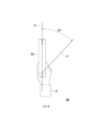
圖3為根據本揭露的實施例的虛擬世界中的追蹤系統的追蹤情境的示意圖。參考圖1到圖3,在追蹤情境300中,圖3為圖2B中的追蹤200B的部分的俯視圖的實施例。應注意,歸因於3DoF裝置120的3DoF感測器122的累積誤差,即使安裝有3DoF裝置120的控制裝置的姿勢不改變,虛擬裝置220的姿勢也可能改變。換句話說,在偏移之後,如圖3中所繪示,虛擬化身AT的臂可能仍在第二對準線L2上對準,但虛擬裝置220可能在第三對準線L3而非第二對準線L2上對準。FIG. 3 is a schematic diagram of a tracking scenario of a tracking system in a virtual world according to an embodiment of the present disclosure. Referring to FIGS. 1-3 , in tracking
具體來說,歸因於3DoF感測器122的累積誤差,3DoF感測器122的當前偏航角可能從3DoF感測器122的正確偏航角漂移。在這種情況下,處理器112可配置成基於來自HMD裝置110的追蹤結果,獲得正確偏航角,且將正確偏航角確定為當前偏航角。更具體地說,處理器112可配置成基於經由相機114的相機資料(例如,第一追蹤結果),確定正確偏航角(即,正確線),且基於經由3DoF感測器122的感測器資料(例如,第二追蹤結果),確定當前偏航角(即,當前線)。在一個實施例中,處理器112可配置成沿著用戶U的臂的方向,確定正確線,且基於3DoF感測器122的感測器資料,確定當前線。此外,處理器112可配置成基於正確線和當前線,校準當前偏航角。因此,可校準3DoF感測器122的累積誤差。Specifically, the current yaw angle of the
在一個實施例中,第二對準線L2可稱為正確線,且第三對準線L3可稱為當前線。此外,正確線可表示3DoF感測器122的正確偏航角,且當前線可表示3DoF感測器122的當前偏航角。(偏航角的)漂移角DFT可定義為正確偏航角(即,正確線)與當前偏航角(即,當前線)之間的角度。在一個實施例中,在漂移角DFT為實際較小時,用戶U可甚至未注意到偏航角的漂移(即,虛擬裝置220的漂移)。然而,在漂移角DFT大於特定值時,用戶U可能會開始注意到偏航角有問題(即,虛擬裝置220的姿勢)。In one embodiment, the second alignment line L2 may be called the correct line, and the third alignment line L3 may be called the current line. Furthermore, the correct line may represent the correct yaw angle of the
為了防止這種情況發生,在漂移角DFT仍較小(即,小於特定值)時,可校準漂移角DFT,以減少累積誤差的影響。也就是說,響應於漂移角DFT小於閾值角,處理器112可配置成將正確線確定為當前線。此外,可基於3DoF感測器122的當前偏航角,校正虛擬裝置220的姿勢。換句話說,處理器112可配置成在校準3DoF感測器122的累積之後,確定對應於安裝有3DoF裝置120的控制裝置的物理姿勢的虛擬裝置220的虛擬裝置姿勢。此外,處理器112可配置成通過顯示器顯示具有虛擬裝置姿勢的虛擬裝置。To prevent this from happening, when the drift angle DFT is still small (i.e., smaller than a specific value), the drift angle DFT can be calibrated to reduce the impact of accumulated errors. That is, in response to the drift angle DFT being less than the threshold angle, the
此外,在漂移角DFT大於特定值時,可基於不同機制,來校準漂移角DFT。也就是說,如果一次性地校準大於特定值的漂移角DFT,那麼用戶U可能會清晰地感覺到對虛擬裝置220的姿勢的校正。因此,在漂移角DFT大於特定值時,漂移角DFT可切割成片段,以用於校準。舉例來說,可在第一時間點校準漂移角DFT的一半。隨後,可在第一時間點之後的第二時間點處校準漂移角DFT的剩餘一半。換句話說,可確定正確線與當前線之間的校準線,以用於兩階段校準。也就是說,處理器112可配置成響應於漂移角DFT不小於閾值角而確定正確線與當前線之間的校準線。此過程還可稱為平滑過程(smooth process)。以此方式,可在用戶U沒有注意到的情況下在背景執行校準。In addition, when the drift angle DFT is greater than a specific value, the drift angle DFT can be calibrated based on different mechanisms. That is, if the drift angle DFT larger than a specific value is calibrated once, the user U may clearly feel the correction of the posture of the
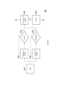
圖4為根據本揭露的實施例的追蹤系統的示意性流程圖。參考圖1到圖4,追蹤方法400可包含步驟S410、步驟S420、步驟S425、步驟S430、步驟S435、步驟S440和步驟S450。Figure 4 is a schematic flow chart of a tracking system according to an embodiment of the present disclosure. Referring to FIGS. 1 to 4 , the
為了增加校準3DoF感測器122的累積誤差的效率,僅在用戶U的手不移動時獲得控制裝置的正確姿勢(即,正確線)是更好的。也就是說,可在追蹤目標(例如,用戶U的手或安裝有3DoF裝置120的控制裝置)為靜態時執行3DoF感測器122的校準。另外,為了在用戶U沒有注意到的情況下校準3DoF感測器122的累積誤差,選擇用戶U常常在虛擬世界中執行的姿勢以用於校準是更好的。舉例來說,在射擊遊戲中,用戶U可能會常常擺出瞄準姿勢。也就是說,瞄準姿勢可用作校準的觸發機制(即,校準姿勢)。在一個實施例中,校準姿勢可包含例如用戶U用安裝有3DoF裝置120的控制裝置瞄準的姿勢、用戶U用安裝有3DoF裝置120的控制裝置指向的姿勢、用戶U的臂為筆直的的姿勢,或其它類似姿勢。In order to increase the efficiency of calibrating the accumulated error of the
在一個實施例中,為了增加校準的效率且在用戶U沒有注意到的情況下執行校準,追蹤方法400可引入靜態檢測演算法和姿勢檢測演算法。也就是說,靜態檢測演算法配置成確定追蹤目標(例如,用戶U的手或安裝有3DoF裝置120的控制裝置)是否為靜態的,且姿勢檢測演算法配置成確定目標姿勢(例如,用戶U的手的手姿勢或安裝有3DoF裝置120的控制裝置的對象姿勢)為校準姿勢或非校準姿勢。In one embodiment, in order to increase the efficiency of calibration and perform calibration without the user U noticing, the
更具體地說,在步驟S410中,追蹤可由追蹤系統100執行。追蹤可包含以下中的至少一個:手追蹤、光學追蹤和對象檢測,或與其他追蹤系統(例如,前述額外裝置)的組合,但本揭露不限於此。在步驟S420中,處理器112可配置成執行靜態檢測演算法。在步驟S425中,處理器112可配置成確定追蹤目標(例如,手或控制裝置)為靜態的或非靜態的。在一個實施例中,處理器112可配置成基於經由相機114的第一追蹤結果,確定追蹤目標為靜態的或非靜態的。在另一實施例中,處理器112可配置成基於經由3DoF裝置120的第二追蹤結果,確定追蹤目標為靜態的或非靜態的。響應於追蹤目標為非靜態的,處理器112可配置成再次執行步驟S420。另一方面,響應於追蹤目標為靜態的,處理器112可配置成執行步驟S440。More specifically, in step S410, tracking may be performed by the
在步驟S430中,處理器112可配置成執行姿勢檢測演算法。類似於追蹤,可基於手追蹤、光學追蹤和經由相機114的對象檢測或額外裝置進行的額外追蹤結果(即,額外資料)中的至少一個,執行姿勢檢測演算法。也就是說,處理器112可配置成基於經由相機114的第一追蹤結果和/或經由額外裝置的額外追蹤結果,執行姿勢檢測演算法。在步驟S435中,處理器112可配置成基於經由相機114的第一追蹤結果,確定追蹤目標的目標姿勢為校準姿勢或非校準姿勢。響應於目標姿勢為非校準姿勢,處理器112可配置成再次執行步驟S430。另一方面,響應於目標姿勢為校準姿勢,處理器112可配置成執行步驟S440。應注意,在一個實施例中,只要符合步驟S425或步驟S435的條件,就可執行步驟S440。在另一實施例中,僅當符合步驟S425和步驟S435的兩個條件時,可執行步驟S440。然而,本揭露並不限於此。In step S430, the
在步驟S440中,可執行3DoF重定向演算法。可輸入3DoF裝置120的當前姿勢P0(即,當前偏航角),且可輸出3DoF裝置120的正確姿勢P1(即,正確偏航角)。在一個實施例中,可基於經由3DoF感測器122的第二追蹤結果,確定當前姿勢P0,且可基於經由相機114的第一追蹤結果,確定正確姿勢P1。在步驟S450中,基於當前姿勢P0與正確姿勢P1之間的差異,處理器112可配置成使用平滑器(smoother)(例如,執行平滑過程)來對差異平滑。隨後,可從平滑器輸出經校準的姿勢P2,以在用戶U沒有注意到的情況下校準3DoF感測器122的累積誤差。In step S440, a 3DoF redirection algorithm may be executed. The current posture P0 (ie, the current yaw angle) of the
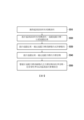
圖5為根據本揭露的實施例的追蹤方法的示意性流程圖。參考圖1到圖5、追蹤方法400可包含步驟S510、步驟S520、步驟S530、步驟S540和步驟S550。FIG. 5 is a schematic flowchart of a tracking method according to an embodiment of the present disclosure. Referring to FIGS. 1 to 5 , the
在步驟S510中,可從3DoF裝置120的3DoF感測器122獲得感測器資料,且可從相機114獲得相機資料。相機資料可包含作為追蹤目標的用戶的身體部位或安裝有3DoF裝置120的控制裝置的影像。在步驟S520中,可基於感測器資料和相機資料追蹤,追蹤目標,以產生追蹤結果。在步驟S530中,可基於追蹤結果,確定追蹤目標為靜態的或非靜態的。在步驟S540中,可基於追蹤結果,確定追蹤目標的目標姿勢。在步驟S550中,響應於追蹤目標為靜態的且目標姿勢為校準姿勢,可在背景中校準3DoF裝置120的累積誤差。In step S510 , sensor data may be obtained from the
另外,追蹤方法400的實施細節可參考圖1到圖4的描述,以獲得足夠教示、建議和實施例,而本文中不冗餘地描述細節。In addition, for implementation details of the
綜上所述,根據追蹤系統100和追蹤方法400,通過檢測校準姿勢,3DoF感測器122可通過將安裝有3DoF裝置120的控制裝置的軸線與用戶U的臂的軸線對準來校準。以此方式,可在用戶U沒有注意到的情況下(例如,在不中斷遊戲體驗的情況下)在背景執行3DoF感測器122的校準。因此,可校正3DoF裝置120的累積誤差,由此增加用戶體驗。In summary, according to the
對於本領域的技術人員將顯而易見的是,可在不脫離本揭露的範圍或精神的情況下對所揭露實施例進行各種修改和變化。鑒於前述內容,希望本揭露涵蓋修改和變化,前提條件是所述修改和變化屬所附申請專利範圍和其等效物的範圍內。It will be apparent to those skilled in the art that various modifications and changes can be made in the disclosed embodiments without departing from the scope or spirit of the disclosure. In view of the foregoing, it is intended that the present disclosure cover modifications and variations provided that they come within the scope of the appended claims and their equivalents.
100:追蹤系統
110:HMD裝置
112:處理器
114:相機
120:三自由度裝置
122:3DoF感測器
200A、200B、300:追蹤情境
220:虛擬裝置
400:追蹤方法
AT:虛擬化身
DFT:漂移角
L1:第一對準線
L2:第二對準線
L3:第三對準線
P0:當前姿勢
P1:正確姿勢
P2:經校準的姿勢
S410、S420、S425、S430、S435、S440、S450、S510、S520、S530、S540、S550:步驟
U:用戶
100:Tracking system
110:HMD device
112: Processor
114:Camera
120:Three degrees of freedom device
122:
圖1為根據本揭露的實施例的追蹤系統的示意圖。 圖2A為根據本揭露的實施例的現實世界中的追蹤系統的追蹤情境的示意圖。 圖2B為根據本揭露的實施例的虛擬世界中的追蹤系統的追蹤情境的示意圖。 圖3為根據本揭露的實施例的虛擬世界中的追蹤系統的追蹤情境的示意圖。 圖4為根據本揭露的實施例的追蹤系統的示意性流程圖。 圖5為根據本揭露的實施例的追蹤方法的示意性流程圖。 Figure 1 is a schematic diagram of a tracking system according to an embodiment of the present disclosure. FIG. 2A is a schematic diagram of a tracking scenario of a tracking system in the real world according to an embodiment of the present disclosure. FIG. 2B is a schematic diagram of a tracking scenario of a tracking system in a virtual world according to an embodiment of the present disclosure. FIG. 3 is a schematic diagram of a tracking scenario of a tracking system in a virtual world according to an embodiment of the present disclosure. Figure 4 is a schematic flow chart of a tracking system according to an embodiment of the present disclosure. FIG. 5 is a schematic flowchart of a tracking method according to an embodiment of the present disclosure.
S510、S520、S530、S540、S550:步驟S510, S520, S530, S540, S550: Steps
Claims (10)
Applications Claiming Priority (2)
| Application Number | Priority Date | Filing Date | Title |
|---|---|---|---|
| US202263392496P | 2022-07-27 | 2022-07-27 | |
| US63/392,496 | 2022-07-27 |
Publications (2)
| Publication Number | Publication Date |
|---|---|
| TWI831718B true TWI831718B (en) | 2024-02-01 |
| TW202404669A TW202404669A (en) | 2024-02-01 |
Family
ID=89622761
Family Applications (1)
| Application Number | Title | Priority Date | Filing Date |
|---|---|---|---|
| TW112128076A TWI831718B (en) | 2022-07-27 | 2023-07-27 | Tracking system and tracking method |
Country Status (3)
| Country | Link |
|---|---|
| US (1) | US12307024B2 (en) |
| CN (1) | CN117472198A (en) |
| TW (1) | TWI831718B (en) |
Families Citing this family (1)
| Publication number | Priority date | Publication date | Assignee | Title |
|---|---|---|---|---|
| US20240272278A1 (en) * | 2023-02-14 | 2024-08-15 | Microsoft Technology Licensing, Llc | Pose detection using multi-chirp fmcw radar |
Citations (6)
| Publication number | Priority date | Publication date | Assignee | Title |
|---|---|---|---|---|
| US20170282062A1 (en) * | 2016-03-30 | 2017-10-05 | Sony Computer Entertainment Inc. | Head-mounted Display Tracking |
| TWM571760U (en) * | 2018-12-21 | Rehabilitation game system | ||
| TW201911133A (en) * | 2017-07-26 | 2019-03-16 | 美商谷歌有限責任公司 | Controller tracking for multiple degrees of freedom |
| US20190318501A1 (en) * | 2018-04-16 | 2019-10-17 | Microsoft Technology Licensing, Llc | Tracking pose of handheld object |
| US20200368616A1 (en) * | 2017-06-09 | 2020-11-26 | Dean Lindsay DELAMONT | Mixed reality gaming system |
| TW202222073A (en) * | 2020-11-22 | 2022-06-01 | 未來市股份有限公司 | Electronic device and method of tracking pose of electronic device |
Family Cites Families (5)
| Publication number | Priority date | Publication date | Assignee | Title |
|---|---|---|---|---|
| US10078377B2 (en) * | 2016-06-09 | 2018-09-18 | Microsoft Technology Licensing, Llc | Six DOF mixed reality input by fusing inertial handheld controller with hand tracking |
| US11086124B2 (en) * | 2018-06-13 | 2021-08-10 | Reavire, Inc. | Detecting velocity state of a device |
| US20200089335A1 (en) * | 2018-09-19 | 2020-03-19 | XRSpace CO., LTD. | Tracking Method and Tracking System Using the Same |
| WO2020214272A1 (en) * | 2019-04-15 | 2020-10-22 | Magic Leap, Inc. | Sensor fusion for electromagnetic tracking |
| US12229332B1 (en) * | 2023-10-24 | 2025-02-18 | Htc Corporation | Tracking system and method |
-
2023
- 2023-07-27 TW TW112128076A patent/TWI831718B/en active
- 2023-07-27 CN CN202310931158.XA patent/CN117472198A/en active Pending
- 2023-07-27 US US18/359,882 patent/US12307024B2/en active Active
Patent Citations (6)
| Publication number | Priority date | Publication date | Assignee | Title |
|---|---|---|---|---|
| TWM571760U (en) * | 2018-12-21 | Rehabilitation game system | ||
| US20170282062A1 (en) * | 2016-03-30 | 2017-10-05 | Sony Computer Entertainment Inc. | Head-mounted Display Tracking |
| US20200368616A1 (en) * | 2017-06-09 | 2020-11-26 | Dean Lindsay DELAMONT | Mixed reality gaming system |
| TW201911133A (en) * | 2017-07-26 | 2019-03-16 | 美商谷歌有限責任公司 | Controller tracking for multiple degrees of freedom |
| US20190318501A1 (en) * | 2018-04-16 | 2019-10-17 | Microsoft Technology Licensing, Llc | Tracking pose of handheld object |
| TW202222073A (en) * | 2020-11-22 | 2022-06-01 | 未來市股份有限公司 | Electronic device and method of tracking pose of electronic device |
Also Published As
| Publication number | Publication date |
|---|---|
| US12307024B2 (en) | 2025-05-20 |
| TW202404669A (en) | 2024-02-01 |
| US20240036656A1 (en) | 2024-02-01 |
| CN117472198A (en) | 2024-01-30 |
Similar Documents
| Publication | Publication Date | Title |
|---|---|---|
| US10521011B2 (en) | Calibration of inertial measurement units attached to arms of a user and to a head mounted device | |
| US10705597B1 (en) | Interactive exercise and training system and method | |
| US10191544B2 (en) | Hand gesture recognition system for controlling electronically controlled devices | |
| US11836302B2 (en) | Motion computing system and method for virtual reality | |
| TWI744606B (en) | Motion detection system, motion detection method and computer-readable recording medium thereof | |
| US20110043446A1 (en) | Computer input device | |
| US20210089162A1 (en) | Calibration of inertial measurement units in alignment with a skeleton model to control a computer system based on determination of orientation of an inertial measurement unit from an image of a portion of a user | |
| TWI829563B (en) | Wearable tracking system and wearable tracking method | |
| TWI855182B (en) | Method and system of modifying position of cursor | |
| TWI831718B (en) | Tracking system and tracking method | |
| US12229332B1 (en) | Tracking system and method | |
| KR20160090042A (en) | Arcade game system by 3D HMD | |
| KR101530340B1 (en) | Motion sensing system for implementing hand position-posture information of user in a three-dimensional virtual space based on a combined motion tracker and ahrs system | |
| TWI874171B (en) | Hand tracking device, system, and method | |
| TW202123691A (en) | Head mounted display system and rotation center correcting method thereof | |
| CN102486677A (en) | Ring sensor interaction system | |
| JP2017126120A (en) | Sighting point position information generator | |
| US20210149479A1 (en) | Head mounted display system and rotation center correcting method thereof | |
| US20250362735A1 (en) | Immersive system and displaying method | |
| TWI818887B (en) | Control system and control method | |
| US12430791B1 (en) | Hand tracking system and method | |
| KR20190056833A (en) | Head mounted control apparatus and method to generate signal for head mounted display | |
| KR20200061861A (en) | Method and apparatus for motion capture interface using multiple fingers | |
| EP3832374A1 (en) | Head mounted display system and rotation center correcting method thereof | |
| CN116804894A (en) | Wearable tracking systems and wearable tracking methods |