TWI801678B - Polarizing plate with retardation layer and image display device using same - Google Patents
Polarizing plate with retardation layer and image display device using same Download PDFInfo
- Publication number
- TWI801678B TWI801678B TW108136721A TW108136721A TWI801678B TW I801678 B TWI801678 B TW I801678B TW 108136721 A TW108136721 A TW 108136721A TW 108136721 A TW108136721 A TW 108136721A TW I801678 B TWI801678 B TW I801678B
- Authority
- TW
- Taiwan
- Prior art keywords
- retardation layer
- layer
- film
- polarizing plate
- retardation
- Prior art date
Links
Images


Classifications
-
- G—PHYSICS
- G02—OPTICS
- G02B—OPTICAL ELEMENTS, SYSTEMS OR APPARATUS
- G02B5/00—Optical elements other than lenses
- G02B5/30—Polarising elements
- G02B5/3083—Birefringent or phase retarding elements
-
- G—PHYSICS
- G02—OPTICS
- G02B—OPTICAL ELEMENTS, SYSTEMS OR APPARATUS
- G02B1/00—Optical elements characterised by the material of which they are made; Optical coatings for optical elements
- G02B1/04—Optical elements characterised by the material of which they are made; Optical coatings for optical elements made of organic materials, e.g. plastics
-
- G—PHYSICS
- G02—OPTICS
- G02B—OPTICAL ELEMENTS, SYSTEMS OR APPARATUS
- G02B1/00—Optical elements characterised by the material of which they are made; Optical coatings for optical elements
- G02B1/10—Optical coatings produced by application to, or surface treatment of, optical elements
- G02B1/14—Protective coatings, e.g. hard coatings
-
- G—PHYSICS
- G02—OPTICS
- G02B—OPTICAL ELEMENTS, SYSTEMS OR APPARATUS
- G02B5/00—Optical elements other than lenses
- G02B5/30—Polarising elements
- G02B5/3025—Polarisers, i.e. arrangements capable of producing a definite output polarisation state from an unpolarised input state
- G02B5/3033—Polarisers, i.e. arrangements capable of producing a definite output polarisation state from an unpolarised input state in the form of a thin sheet or foil, e.g. Polaroid
-
- H—ELECTRICITY
- H10—SEMICONDUCTOR DEVICES; ELECTRIC SOLID-STATE DEVICES NOT OTHERWISE PROVIDED FOR
- H10K—ORGANIC ELECTRIC SOLID-STATE DEVICES
- H10K59/00—Integrated devices, or assemblies of multiple devices, comprising at least one organic light-emitting element covered by group H10K50/00
- H10K59/50—OLEDs integrated with light modulating elements, e.g. with electrochromic elements, photochromic elements or liquid crystal elements
Landscapes
- Physics & Mathematics (AREA)
- General Physics & Mathematics (AREA)
- Optics & Photonics (AREA)
- Polarising Elements (AREA)
- Liquid Crystal (AREA)
- Electroluminescent Light Sources (AREA)
- Devices For Indicating Variable Information By Combining Individual Elements (AREA)
Abstract
本發明提供一種薄型、處理性優異且光學特性優異的附相位差層之偏光板。本發明附相位差層之偏光板具有偏光板與相位差層,該偏光板包含偏光膜與位於偏光膜之至少一側的保護層。偏光膜係以含二色性物質之聚乙烯醇系樹脂薄膜所構成,其厚度為8μm以下,單體透射率為43.0%以上,且在波長550nm下每1μm厚度的正交吸光度為0.85以上。相位差層的Re(550)為100nm~190nm,Re(450)/Re(550)為0.8以上且小於1。相位差層的慢軸與該偏光膜的吸收軸形成之角度為40°~50°。The present invention provides a polarizing plate with a retardation layer that is thin, has excellent handling properties, and has excellent optical properties. The polarizing plate with retardation layer of the present invention has a polarizing plate and a retardation layer, and the polarizing plate includes a polarizing film and a protective layer on at least one side of the polarizing film. The polarizing film is made of polyvinyl alcohol-based resin film containing dichroic substances, its thickness is less than 8 μm, the single transmittance is more than 43.0%, and the orthogonal absorbance per 1 μm thickness is more than 0.85 at a wavelength of 550 nm. Re(550) of the retardation layer is 100 nm to 190 nm, and Re(450)/Re(550) is 0.8 or more and less than 1. The angle formed by the slow axis of the retardation layer and the absorption axis of the polarizing film is 40°-50°.
Description
本發明涉及附相位差層之偏光板及使用其之影像顯示裝置。The invention relates to a polarizing plate with a retardation layer and an image display device using the polarizing plate.
發明背景 近年來,代表上有液晶顯示裝置及電致發光(EL)顯示裝置(例如有機EL顯示裝置、無機EL顯示裝置)之影像顯示裝置急速普及。影像顯示裝置代表上係使用偏光板及相位差板。在實際應用上,廣泛使用偏光板與相位差板一體化而成的附相位差層之偏光板(例如專利文獻1),而最近隨著對於影像顯示裝置薄型化之需求增強,對於附相位差層之偏光板的薄型化需求亦增強。又,近年來對於彎曲的影像顯示裝置及/或可撓曲或可彎折的影像顯示裝置之需求提高,而對於偏光板及附相位差層之偏光板亦要求更進一步的薄型化及更進一步的柔軟化。出於將附相位差層之偏光板薄型化之目的,正在進行對厚度影響較大的偏光膜之保護層及相位差薄膜的薄型化。惟,若將保護層及相位差薄膜薄型化,則偏光膜之收縮的影響會相對變大,而產生影像顯示裝置翹曲及附相位差層之偏光板的操作性降低之問題。Background of the invention In recent years, image display devices representing liquid crystal display devices and electroluminescent (EL) display devices (such as organic EL display devices and inorganic EL display devices) have become popular rapidly. Image display devices typically use polarizers and retardation plates. In practical applications, a polarizing plate with a retardation layer integrated with a polarizing plate and a retardation plate is widely used (for example, Patent Document 1). The demand for thinner polarizing plates is also enhanced. In addition, in recent years, the demand for curved image display devices and/or flexible or bendable image display devices has increased, and further thinning and further improvements are required for polarizers and polarizers with retardation layers. softening. For the purpose of reducing the thickness of the polarizing plate with a retardation layer, the thickness of the protective layer of the polarizing film and the retardation film, which have a large influence on the thickness, are being reduced. However, if the protective layer and the retardation film are thinned, the influence of the shrinkage of the polarizing film will be relatively greater, and problems such as warping of the image display device and poor operability of the polarizing plate with the retardation layer will arise.
為了解決上述之問題,連偏光膜亦需進行薄型化。惟,若僅減薄偏光膜之厚度,則光學特性會降低。更具體而言,係具有抵換關係之偏光度與單體透射率的其中一者或兩者降低至實際應用上無法容許的程度。結果會使附相位差層之偏光板的光學特性亦變得不足。In order to solve the above problems, even the polarizing film needs to be thinned. However, if only the thickness of the polarizing film is reduced, the optical properties will be reduced. More specifically, one or both of the degree of polarization and the transmittance of the monomer that have a trade-off relationship is reduced to an unacceptable level in practical applications. As a result, the optical characteristics of the polarizing plate with the retardation layer also become insufficient.
先前技術文獻 專利文獻 專利文獻1:日本專利第3325560號公報prior art literature patent documents Patent Document 1: Japanese Patent No. 3325560
發明概要 發明欲解決之課題 本發明是為了解決上述以往課題而成者,其主要目的在於提供一種薄型、處理性優異且光學特性優異的附相位差層之偏光板。Summary of the invention The problem to be solved by the invention The present invention is made to solve the above-mentioned conventional problems, and its main object is to provide a polarizing plate with a retardation layer that is thin, has excellent handling properties, and has excellent optical properties.
用以解決課題之手段 本發明附相位差層之偏光板具有偏光板與相位差層,該偏光板包含偏光膜與位於該偏光膜之至少一側的保護層。該偏光膜係以含二色性物質之聚乙烯醇系樹脂薄膜所構成,其厚度為8μm以下,單體透射率為43.0%以上,且在波長550nm下每1μm厚度的正交吸光度為0.85以上。該相位差層的Re(550)為100nm~190nm,Re(450)/Re(550)為0.8以上且小於1,該相位差層之慢軸與該偏光膜之吸收軸形成之角度為40°~50°。 在一實施形態中,上述保護層係由彈性係數為3000MPa以上之基材構成。 在一實施形態中,上述附相位差層之偏光板的總厚度為90μm以下,正面反射色相為3.5以下,並且上述保護層係由彈性係數為3000MPa以上之樹脂薄膜構成。 在一實施形態中,上述保護層係由三醋酸纖維素系樹脂薄膜構成。 在一實施形態中,上述偏光板包含上述偏光膜與僅配置於上述偏光膜之一側的上述保護層,上述相位差層係透過黏著劑層貼合於上述偏光膜。 在一實施形態中,上述相位差層係由聚碳酸酯系樹脂薄膜構成。 在一實施形態中,上述相位差層係由具有40μm以下之厚度的聚碳酸酯系樹脂薄膜構成。 在一實施形態中,上述偏光膜在波長470nm下之正交吸光度A470 與在波長600nm下之正交吸光度A600 之比(A470 /A600 )為0.7~2.00。 在一實施形態中,上述偏光膜的正交b值大於-10且在+10以下。 在一實施形態中,上述偏光膜在波長550nm下之正交吸光度A550 在2.0以上。 在一實施形態中,上述附相位差層之偏光板於上述相位差層之外側更具有另一相位差層,該另一相位差層之折射率特性顯示nz>nx=ny之關係。 在一實施形態中,上述附相位差層之偏光板於上述相位差層之外側更具有導電層或附導電層之各向同性基材。 在一實施形態中,上述附相位差層之偏光板為長條狀,上述偏光膜於長條方向上具有吸收軸,且上述相位差層為於相對於長條方向呈40°~50°之角度之方向上具有慢軸之斜向延伸薄膜。在一實施形態中,上述附相位差層之偏光板係捲繞成捲狀。 根據本發明之另一面向提供一種影像顯示裝置。該影像顯示裝置具備上述附相位差層之偏光板。 在一實施形態中,上述影像顯示裝置係有機電致發光顯示裝置或無機電致發光顯示裝置。Means for Solving the Problems The polarizing plate with a retardation layer of the present invention has a polarizing plate and a retardation layer, and the polarizing plate includes a polarizing film and a protective layer on at least one side of the polarizing film. The polarizing film is composed of a polyvinyl alcohol-based resin film containing a dichroic substance, with a thickness of 8 μm or less, a single transmittance of 43.0% or more, and an orthogonal absorbance of 0.85 or more per 1 μm thickness at a wavelength of 550 nm . Re(550) of the retardation layer is 100nm~190nm, Re(450)/Re(550) is more than 0.8 and less than 1, the angle formed by the slow axis of the retardation layer and the absorption axis of the polarizing film is 40° ~50°. In one embodiment, the above-mentioned protective layer is composed of a base material having an elastic modulus of 3000 MPa or more. In one embodiment, the total thickness of the polarizing plate with retardation layer is 90 μm or less, the front reflection hue is 3.5 or less, and the protective layer is made of a resin film with an elastic modulus of 3000 MPa or more. In one embodiment, the above-mentioned protective layer is formed of a cellulose triacetate resin film. In one embodiment, the polarizing plate includes the polarizing film and the protective layer disposed only on one side of the polarizing film, and the retardation layer is bonded to the polarizing film through an adhesive layer. In one embodiment, the retardation layer is formed of a polycarbonate-based resin film. In one embodiment, the retardation layer is formed of a polycarbonate-based resin film having a thickness of 40 μm or less. In one embodiment, the ratio (A 470 /A 600 ) of the orthogonal absorbance A 470 at a wavelength of 470 nm to the orthogonal absorbance A 600 at a wavelength of 600 nm of the polarizing film is 0.7˜2.00. In one embodiment, the orthogonal b value of the polarizing film is greater than -10 and not more than +10. In one embodiment, the orthogonal absorbance A 550 of the polarizing film at a wavelength of 550 nm is 2.0 or more. In one embodiment, the above-mentioned polarizing plate with a retardation layer further has another retardation layer outside the above-mentioned retardation layer, and the refractive index characteristic of the another retardation layer shows the relationship of nz>nx=ny. In one embodiment, the polarizing plate with a retardation layer further has a conductive layer or an isotropic substrate with a conductive layer outside the retardation layer. In one embodiment, the above-mentioned polarizing plate with a retardation layer is strip-shaped, the above-mentioned polarizing film has an absorption axis in the strip direction, and the above-mentioned retardation layer is 40°~50° with respect to the strip direction. An obliquely stretched film with a slow axis in the direction of the angle. In one embodiment, the polarizing plate with a retardation layer is wound in a roll shape. According to another aspect of the present invention, an image display device is provided. The image display device includes the above-mentioned polarizing plate with a retardation layer. In one embodiment, the above image display device is an organic electroluminescence display device or an inorganic electroluminescence display device.
發明效果 根據本發明,藉由組合採用以下方法可獲得雖為薄型卻具有極優異光學特性的偏光膜:對聚乙烯醇(PVA)系樹脂添加鹵化物(代表上為碘化鉀)、包含空中輔助延伸及水中延伸之2段延伸、以及以加熱輥進行之乾燥及收縮。藉由使用所述偏光膜,可實現薄型、處理性優異且光學特性優異的附相位差層之偏光板。Invention effect According to the present invention, a thin polarizing film having excellent optical characteristics can be obtained by combining the following methods: adding a halide (typically potassium iodide) to a polyvinyl alcohol (PVA)-based resin, including auxiliary stretching in the air and water 2-stage stretching, drying and shrinking with heated rolls. By using the above-mentioned polarizing film, it is possible to realize a polarizing plate with a retardation layer that is thin, has excellent handling properties, and has excellent optical characteristics.
用以實施發明之形態 以下說明本發明之實施形態,惟本發明不受該等實施形態限定。form for carrying out the invention Embodiments of the present invention will be described below, but the present invention is not limited to these embodiments.
(用語及符號之定義) 本說明書中之用語及符號之定義如下。 (1)折射率(nx、ny、nz) 「nx」為面內折射率成最大的方向(亦即慢軸方向)之折射率,「ny」為在面內與慢軸正交之方向(亦即快軸方向)之折射率,而「nz」為厚度方向之折射率。 (2)面內相位差(Re) 「Re(λ)」係於23℃下以波長λnm之光測得之面內相位差。例如,「Re(550)」係於23℃下以波長550nm之光測得之面內相位差。Re(λ)可於令層(薄膜)之厚度為d(nm)時,藉由式:Re(λ)=(nx-ny)×d求得。 (3)厚度方向之相位差(Rth) 「Rth(λ)」係於23℃下以波長λnm之光測得之厚度方向的相位差。例如,「Rth(550)」係於23℃下以波長550nm之光測得之厚度方向的相位差。Rth(λ)可於令層(薄膜)厚度為d(nm)時,藉由式:Rth(λ)=(nx-nz)×d求得。 (4)Nz係數 Nz係數可以Nz=Rth/Re求得。 (5)角度 本說明書中提及角度時,該角度包含相對於基準方向之順時針及逆時針兩者。因此,例如「45°」係指±45°。(Definition of terms and symbols) The definitions of terms and symbols in this manual are as follows. (1) Refractive index (nx, ny, nz) "nx" is the refractive index in the direction where the in-plane refractive index becomes the largest (that is, the direction of the slow axis), "ny" is the refractive index in the direction that is perpendicular to the slow axis in the plane (that is, the direction of the fast axis), and " nz" is the refractive index in the thickness direction. (2) In-plane retardation (Re) "Re(λ)" is the in-plane retardation measured with light of wavelength λnm at 23°C. For example, "Re(550)" is the in-plane retardation measured at 23°C with light having a wavelength of 550nm. Re(λ) can be calculated by the formula: Re(λ)=(nx-ny)×d when the thickness of the layer (thin film) is d(nm). (3) Phase difference in thickness direction (Rth) "Rth(λ)" is the retardation in the thickness direction measured with light of wavelength λnm at 23°C. For example, "Rth(550)" is the retardation in the thickness direction measured at 23°C with light with a wavelength of 550nm. Rth(λ) can be obtained by the formula: Rth(λ)=(nx-nz)×d when the thickness of the layer (film) is d(nm). (4) Nz coefficient The Nz coefficient can be obtained by Nz=Rth/Re. (5) angle When an angle is mentioned in this specification, the angle includes both clockwise and counterclockwise relative to a reference direction. Thus, for example, "45°" means ±45°.
A.附相位差層之偏光板之整體構成
圖1係本發明之一實施形態之附相位差層之偏光板的概略截面圖。本實施形態之附相位差層之偏光板100具有偏光板10與相位差層20。偏光板10包含:偏光膜11、配置於偏光膜11之一側的第1保護層12、及配置於偏光膜11之另一側的第2保護層13。亦可因應目的省略第1保護層12及第2保護層13之其中一者。例如,當相位差層20可作為偏光膜11之保護層發揮功能時,亦可省略第2保護層13。於本發明實施形態中,偏光膜代表上係以含二色性物質之聚乙烯醇系樹脂薄膜所構成。偏光膜的厚度為8μm以下,單體透射率為43.0%以上,且在波長550nm下每厚度1μm的正交吸光度(以下稱為單位吸光度)為0.85以上。A. Overall composition of polarizing plate with retardation layer
Fig. 1 is a schematic cross-sectional view of a polarizing plate with a retardation layer according to an embodiment of the present invention. The polarizing plate with
如圖2所示,另一實施形態之附相位差層之偏光板101中,亦可設有另一相位差層50以及/或者導電層或附導電層之各向同性基材60。另一相位差層50以及導電層或附導電層之各向同性基材60代表上可設於相位差層20之外側(與偏光板10相反之側)。另一相位差層代表上折射率特性係顯示nz>nx=ny之關係。另一相位差層50以及導電層或附導電層之各向同性基材60代表上係從相位差層20側起依序設置。另一相位差層50以及導電層或附導電層之各向同性基材60代表上係可因應需要設置之任意層,可省略任一者或兩者。此外,為求方便,有時會將相位差層20稱為第1相位差層,且將另一相位差層50稱為第2相位差層。另外,在可設置導電層或附導電層之各向同性基材時,附相位差層之偏光板可應用於在影像顯示單元(例如有機EL單元)與偏光板間組入觸控感測器而成的所謂內觸控面板型輸入顯示裝置。As shown in FIG. 2 , another retardation layer 50 and/or a conductive layer or an isotropic substrate with a
本發明實施形態中,第1相位差層20的Re(550)為100nm~190nm,Re(450)/Re(550)為0.8以上且小於1。並且,第1相位差層20的慢軸與偏光膜11的吸收軸形成之角度為40°~50°。In an embodiment of the present invention, Re(550) of the
上述實施形態可適當組合,亦可於上述實施形態之構成要素添加業界中顯明的變更。例如亦可將在第2相位差層50的外側設置附導電層之各向同性基材60的構成替換為在光學上等效之構成(例如第2相位差層與導電層之積層體)。The above-mentioned embodiments may be combined appropriately, and changes obvious in the industry may be added to the constituent elements of the above-mentioned embodiments. For example, the structure in which the
本發明實施形態之附相位差層之偏光板亦可更包含有其他相位差層。其他相位差層之光學特性(例如折射率特性、面內相位差、Nz係數、光彈性係數)、厚度、配置位置等可按目適當設定。The polarizing plate with a retardation layer according to the embodiment of the present invention may further include other retardation layers. The optical characteristics (such as refractive index characteristics, in-plane retardation, Nz coefficient, photoelastic coefficient), thickness, arrangement position, etc. of other retardation layers can be appropriately set according to the purpose.
本發明之附相位差層之偏光板可為薄片狀亦可為長條狀。本說明書中所謂「長條狀」意指相對於寬度而言長度足夠長的細長形狀,舉例而言包含相對於寬度而言長度為10倍以上之細長形狀,且宜為20倍以上之細長形狀。長條狀附相位差層之偏光板可捲成捲狀。附相位差層之偏光板為長條狀時,偏光板及相位差層皆為長條狀。此時,偏光膜宜於長條方向上具有吸收軸。第1相位差層宜為於相對於長條方向呈40°~50°之角度之方向上具有慢軸之斜向延伸薄膜。偏光膜及第1相位差層只要為所述構成,即可藉由捲對捲製作附相位差層之偏光板。The polarizing plate with a retardation layer of the present invention may be in the form of a thin sheet or a strip. The term "elongated" in this specification means an elongated shape that is sufficiently long relative to the width, including, for example, an elongated shape whose length is 10 times or more relative to the width, preferably 20 times or more. . The long polarizer with retardation layer can be rolled into a roll. When the polarizing plate with the retardation layer is long, both the polarizing plate and the retardation layer are long. In this case, the polarizing film preferably has an absorption axis in the longitudinal direction. The first retardation layer is preferably an obliquely stretched film having a slow axis in a direction at an angle of 40° to 50° with respect to the elongated direction. As long as the polarizing film and the first retardation layer have the above configuration, a polarizing plate with a retardation layer can be produced by roll-to-roll.
於實際使用上,可於相位差層之與偏光板相反之側設置黏著劑層(未圖示),且附相位差層之偏光板可貼附於影像顯示單元。並且,黏著劑層之表面宜在附相位差層之偏光板供於使用之前暫時黏附剝離薄膜。藉由暫時黏附剝離薄膜,可在保護黏著劑層的同時形成捲料。In actual use, an adhesive layer (not shown) can be provided on the opposite side of the retardation layer to the polarizer, and the polarizer with the retardation layer can be attached to the image display unit. Also, the surface of the adhesive layer is preferably temporarily attached with a release film before the polarizing plate with a retardation layer is used. By temporarily adhering the release film, a web can be formed while protecting the adhesive layer.
附相位差層之偏光板的正面反射色相(√(a*2 +b*2 ))宜為3.5以下,且宜為3.0以下。正面反射色相只要在上述範圍內,即能抑制所不期望之著色等,結果可獲得反射特性佳之附相位差層之偏光板。The front reflection hue (√(a *2 +b *2 )) of the polarizing plate with a retardation layer is preferably 3.5 or less, and more preferably 3.0 or less. As long as the front reflection hue is within the above range, undesired coloring and the like can be suppressed, and as a result, a polarizing plate with a retardation layer having excellent reflection characteristics can be obtained.
附相位差層之偏光板的總厚度宜為140μm以下,且宜為120μm以下,更宜為100μm以下,且以90μm以下更佳,又以85μm以下更佳。總厚度的下限例如可為30μm。根據本發明實施形態,可實現如所述極薄之附相位差層之偏光板。所述附相位差層之偏光板可具有極優異之可撓性及彎折耐久性。所述附相位差層之偏光板尤可適於應用於彎曲的影像顯示裝置及/或可撓曲或彎折的影像顯示裝置。另外,所謂附相位差層之偏光板的總厚度係指扣除用以使附相位差層之偏光板與面板或玻璃等外部被黏體密著的黏著劑層後,構成附相位差層之偏光板的所有層之厚度合計(亦即附相位差層之偏光板的總厚度不包含用以將附相位差層之偏光板貼附至影像顯示單元等鄰接構件的黏著劑層及可暫時黏附於其表面的剝離薄膜之厚度)。The total thickness of the polarizing plate with retardation layer is preferably not more than 140 μm, more preferably not more than 120 μm, more preferably not more than 100 μm, more preferably not more than 90 μm, and more preferably not more than 85 μm. The lower limit of the total thickness may be, for example, 30 μm. According to the embodiment of the present invention, it is possible to realize a polarizing plate with an extremely thin retardation layer as described above. The polarizing plate with retardation layer can have excellent flexibility and bending durability. The polarizing plate with a retardation layer is particularly suitable for application in curved image display devices and/or flexible or bendable image display devices. In addition, the total thickness of the polarizing plate with a retardation layer refers to the polarized light with a retardation layer after deducting the adhesive layer used to make the polarizing plate with a retardation layer adhere to an external adherend such as a panel or glass. The total thickness of all layers of the plate (that is, the total thickness of the polarizing plate with a retardation layer does not include the adhesive layer used to attach the polarizing plate with a retardation layer to adjacent components such as image display units and temporarily adhered to The thickness of the release film on its surface).
以下針對附相位差層之偏光板的構成要素進行更詳細說明。The constituent elements of the polarizing plate with retardation layer will be described in more detail below.
B.偏光板
B-1.偏光膜
偏光膜11如上述,厚度在8μm以下,單體透射率為43.0%以上,且在波長550nm下之單位吸光度為0.85以上。一般而言,單體透射率與單位偏光度具有抵換關係,故若提升單體透射率則單位偏光度會降低,而若提升單位偏光度則單體透射率會降低。因此,以往難以將滿足單體透射率為43.0%以上且在波長550nm下之單位偏光度為0.85以上之光學特性的薄型偏光膜供於實際應用。本發明特徵之一為:使用單體透射率為43.0%以上且在波長550nm下之單位吸光度為0.85以上這般具有優異光學特性的薄型偏光膜。B. Polarizer
B-1. Polarizing film
As mentioned above, the
偏光膜的厚度宜為1μm~8μm,1μm~7μm較佳,2μm~5μm更佳。The thickness of the polarizing film is preferably 1 μm to 8 μm, preferably 1 μm to 7 μm, and more preferably 2 μm to 5 μm.
偏光膜宜在波長380nm~780nm之任一波長下顯示吸收二色性。偏光膜之單體透射率宜為44.0%以下,更宜為43.5%以下。偏光膜的偏光度宜為99.990%以上,且宜為99.998%以下。上述單體透射率代表上係使用紫外線可見光分光光度計來測定並進行光視效能校正所得之Y值。上述偏光度代表上係基於使用紫外線可見光分光光度計測定並進行光視效能校正所得之平行透射率Tp及正交透射率Tc,透過下述式來求得。 偏光度(%)={(Tp-Tc)/(Tp+Tc)}1/2 ×100The polarizing film should exhibit absorption dichroism at any wavelength between 380nm and 780nm. The monomer transmittance of the polarizing film is preferably not more than 44.0%, more preferably not more than 43.5%. The degree of polarization of the polarizing film is preferably more than 99.990% and less than 99.998%. The above-mentioned monomer transmittance represents the Y value obtained by measuring with an ultraviolet-visible light spectrophotometer and correcting for optical performance. The above-mentioned degree of polarization is representatively based on the parallel transmittance Tp and the cross transmittance Tc obtained by using an ultraviolet-visible spectrophotometer and correcting the optical performance, and obtained through the following formula. Degree of polarization (%)={(Tp-Tc)/(Tp+Tc)} 1/2 ×100
在一實施形態中,8μm以下的薄型偏光膜之透射率代表上係以偏光膜(表面之折射率:1.53)與保護薄膜(折射率:1.50)之積層體為測定對象,使用紫外線可見光分光光度計來測定。因應偏光膜表面之折射率及/或保護薄膜之與空氣界面接觸的表面之折射率,在各層界面上的反射率會有所變化,結果會有透射率之測定值產生變化之情形。因此,舉例而言在使用折射率非1.50之保護薄膜時,亦可因應保護薄膜之與空氣界面接觸的表面之折射率來校正透射率之測定值。具體而言,透射率之校正值C係使用保護薄膜及空氣層之界面上與透射軸平行的偏光之反射率R1 (透射軸反射率),以以下式來表示。 C=R1 -R0 R0 =((1.50-1)2 /(1.50+1)2 )×(T1 /100) R1 =((n1 -1)2 /(n1 +1)2 )×(T1 /100) 在此,R0 為使用折射率為1.50之保護薄膜時之透射軸反射率,n1 為所使用之保護薄膜的折射率,而T1 為偏光膜之透射率。舉例而言,在使用表面折射率為1.53之基材(環烯烴系薄膜、附硬塗層之薄膜等)作為保護薄膜時,校正量C為約0.2%。此時,將測得之透射率加上0.2%,可將表面折射率為1.53之偏光膜換算成使用折射率為1.50之保護薄膜時之透射率。另,經依上述式進行計算,在使偏光膜之透射率T1 變化了2%後之校正值C的變化量為0.03%以下,故而偏光膜之透射率對校正值C之值的影響是有限的。又,在保護薄膜具有表面反射以外之吸收時,可依吸收量來進行適當的校正。In one embodiment, the transmittance of a thin polarizing film below 8 μm is representative of a laminate of a polarizing film (refractive index of the surface: 1.53) and a protective film (refractive index: 1.50) as the measurement object, using ultraviolet visible light spectrophotometry meter to measure. Due to the refractive index of the surface of the polarizing film and/or the refractive index of the surface of the protective film in contact with the air interface, the reflectance at the interface of each layer will change, resulting in a change in the measured value of the transmittance. Therefore, for example, when using a protective film with a refractive index other than 1.50, the measured value of the transmittance can also be corrected according to the refractive index of the surface of the protective film in contact with the air interface. Specifically, the corrected value C of the transmittance is represented by the following formula using the reflectance R 1 (transmission axis reflectance) of polarized light parallel to the transmission axis at the interface between the protective film and the air layer. C=R 1 -R 0 R 0 =((1.50-1) 2 /(1.50+1) 2 )×(T 1 /100) R 1 =((n 1 -1) 2 /(n 1 +1) 2 )×(T 1 /100) Here, R 0 is the reflectance on the transmission axis when using a protective film with a refractive index of 1.50, n 1 is the refractive index of the protective film used, and T 1 is the transmittance of the polarizing film Rate. For example, when using a substrate with a surface refractive index of 1.53 (cycloolefin-based film, hard-coated film, etc.) as a protective film, the correction amount C is about 0.2%. At this time, add 0.2% to the measured transmittance to convert the polarizing film with a surface refractive index of 1.53 into the transmittance when using a protective film with a refractive index of 1.50. In addition, after calculating according to the above formula, the change of the correction value C after changing the transmittance T1 of the polarizing film by 2% is less than 0.03%, so the influence of the transmittance of the polarizing film on the value of the correction value C is limited. Also, when the protective film has absorption other than surface reflection, appropriate correction can be made according to the amount of absorption.
偏光膜在波長550nm下之單位吸光度如上述為0.85以上,宜為0.9以上,且宜為1.0以上,更宜為1.3以上。單位吸光度的上限例如可為1.9。在波長λnm下之正交吸光度Aλ 可基於上述正交透射率Tc利用下述式求得。 正交吸光度=log10(100/Tc) 在波長550nm下之單位吸光度可藉由將上述所得正交吸光度A550 除以厚度來求得。此外,附相位差層之偏光板的單位吸光度實質上係對應於偏光膜的單位吸光度。 附相位差層之偏光板用於有機電致發光(EL)顯示裝置及無機EL顯示裝置(例如量子點顯示裝置)時,正交吸光度A550 例如可為2.0以上(例如單位吸光度為0.85以上且厚度為2.5μm以上)。附相位差層之偏光板用於液晶顯示裝置時,正交吸光度A550 例如可為3.0以上。The unit absorbance of the polarizing film at a wavelength of 550 nm is above 0.85, preferably above 0.9, preferably above 1.0, more preferably above 1.3, as described above. The upper limit of the unit absorbance may be 1.9, for example. The cross-absorbance A λ at a wavelength of λ nm can be obtained by the following formula based on the above-mentioned cross-transmittance Tc. Orthogonal absorbance=log10(100/Tc) The unit absorbance at a wavelength of 550 nm can be obtained by dividing the above obtained orthogonal absorbance A 550 by the thickness. In addition, the unit absorbance of the polarizing plate with retardation layer is substantially corresponding to the unit absorbance of the polarizing film. When the polarizing plate with retardation layer is used in organic electroluminescent (EL) display devices and inorganic EL display devices (such as quantum dot display devices), the orthogonal absorbance A 550 can be, for example, more than 2.0 (for example, the unit absorbance is more than 0.85 and thickness of 2.5 μm or more). When the polarizing plate with a retardation layer is used in a liquid crystal display device, the crossed absorbance A 550 can be, for example, 3.0 or more.
較理想的是,偏光膜在波長470nm下之正交吸光度A470 與在波長600nm下之正交吸光度A600 之比(A470 /A600 )為0.7以上,且宜為0.75以上,更宜為0.80以上,尤宜為0.85以上。比(A470 /A600 )宜為2.00以下,且宜為1.33以下。若比(A470 /A600 )在所述範圍內,則可在可見光全區域皆實現良好的偏光性能。在薄型偏光膜的碘量受限的前提下,依靠以往技術難以將上述單位吸光度及比(A470 /A600 )兩者控制在期望範圍內,但本發明所使用之偏光膜則可將該等兩者控制在期望範圍內。More ideally, the ratio (A 470 /A 600 ) of the orthogonal absorbance A 470 of the polarizing film at a wavelength of 470nm to the orthogonal absorbance A 600 of a wavelength of 600nm is 0.7 or more, preferably 0.75 or more, more preferably More than 0.80, especially more than 0.85. The ratio (A 470 /A 600 ) is preferably 2.00 or less, and is preferably 1.33 or less. If the ratio (A 470 /A 600 ) is within the above range, good polarization performance can be achieved in the entire range of visible light. Under the premise that the amount of iodine in the thin polarizing film is limited, it is difficult to control the above-mentioned unit absorbance and the ratio (A 470 /A 600 ) within the desired range by relying on the prior art, but the polarizing film used in the present invention can Keep both of them within the desired range.
並且,偏光膜的正交b值例如大於-10,且宜為-7以上,更宜為-5以上。正交b值宜為+10以下,且宜為+5以下。正交b值係表示在將偏光膜(最終為附相位差層之偏光板)配置為正交狀態時的色相,該數值之絕對值愈大,意味著正交色相(影像顯示裝置之黑顯示)看起來愈帶有色調。例如在正交b值為-10以下即較低時,黑顯示看起來會帶有藍色,而顯示性能降低。亦即,根據本發明之實施形態可獲得可在黑顯示時實現優異色相之附相位差層之偏光板。此外,正交b值可以利用以V-7100為代表之分光光度計測定。In addition, the orthogonal b value of the polarizing film is, for example, greater than -10, preferably -7 or greater, more preferably -5 or greater. The orthogonal b value is preferably +10 or less, and preferably +5 or less. The orthogonal b value indicates the hue when the polarizing film (finally a polarizing plate with a retardation layer) is arranged in an orthogonal state. The larger the absolute value of the value, it means the orthogonal hue (black display of the image display device) ) looks more tinted. For example, when the orthogonal b value is lower than -10, that is, a black display will appear bluish, and the display performance will be degraded. That is, according to the embodiment of the present invention, a polarizing plate with a retardation layer capable of realizing an excellent hue in black display can be obtained. In addition, the orthogonal b value can be measured using a spectrophotometer represented by V-7100.
偏光膜可採用任意適當的偏光膜。偏光膜在代表上可使用兩層以上之積層體來製作。Any suitable polarizing film can be used as the polarizing film. Polarizing film can typically be produced using a laminate of more than two layers.
使用積層體獲得之偏光膜的具體例,可舉出使用樹脂基材與經塗佈形成於該樹脂基材之PVA系樹脂層的積層體而獲得之偏光膜。使用樹脂基材與經塗佈形成於該樹脂基材之PVA系樹脂層的積層體而獲得之偏光膜,例如可以藉由以下方式來製作:將PVA系樹脂溶液塗佈於樹脂基材,並使其乾燥而於樹脂基材上形成PVA系樹脂層,而獲得樹脂基材與PVA系樹脂層的積層體;及,將該積層體延伸及染色而將PVA系樹脂層製成偏光膜。本實施形態中,延伸代表上包含使積層體浸漬於硼酸水溶液中並進行延伸。並且視需要,延伸可更包含在硼酸水溶液中進行延伸前在高溫(例如95℃以上)下將積層體進行空中延伸。可以直接使用所得樹脂基材/偏光膜之積層體(即,亦可將樹脂基材作為偏光膜之保護層),亦可從樹脂基材/偏光膜之積層體剝離樹脂基材並於該剝離面按目的積層任意適當的保護層後來使用。所述偏光膜之製造方法的詳細內容,例如記載於日本專利特開2012-73580號公報。本說明書中係援用該公報整體之記載作為參考。Specific examples of the polarizing film obtained using a laminate include a polarizing film obtained using a laminate of a resin base material and a PVA-based resin layer formed by coating on the resin base material. A polarizing film obtained by using a laminate of a resin substrate and a PVA-based resin layer coated and formed on the resin substrate can be produced, for example, by applying a PVA-based resin solution to the resin substrate, and It is dried to form a PVA-based resin layer on the resin substrate to obtain a laminate of the resin substrate and the PVA-based resin layer; and the laminate is stretched and dyed to make the PVA-based resin layer into a polarizing film. In this embodiment, stretching typically includes immersing the laminate in an aqueous solution of boric acid and stretching it. And, if necessary, the stretching may further include stretching the laminate in air at a high temperature (for example, 95° C. or higher) before stretching in a boric acid aqueous solution. The laminate of the obtained resin substrate/polarizing film can be directly used (that is, the resin substrate can also be used as a protective layer of the polarizing film), or the resin substrate can be peeled off from the laminate of the resin substrate/polarizing film and then Laminate any suitable protective layer according to the purpose and use it later. The details of the manufacturing method of the said polarizing film are described in Unexamined-Japanese-Patent No. 2012-73580, for example. In this specification, the entire description of the publication is incorporated by reference.
偏光膜之製造方法代表上包含下列步驟:於長條狀熱塑性樹脂基材之單側形成含有鹵化物與聚乙烯醇系樹脂之聚乙烯醇系樹脂層,而製成積層體;及,對上述積層體依序施行空中輔助延伸處理、染色處理、水中延伸處理與乾燥收縮處理,該乾燥收縮處理係將上述積層體沿長邊方向輸送的同時進行加熱,藉此使其於寬度方向收縮2%以上。藉此,可提供具有優異光學特性之偏光膜,其厚度在8μm以下,單體透射率為43.0%以上,且在波長550nm下之單位吸光度在0.85以上。亦即,藉由導入輔助延伸,即便是在將PVA塗佈於熱塑性樹脂上時仍可提升PVA之結晶性,而可達成高光學特性。又,同時事先提高PVA之定向性,可防止在之後的染色步驟或延伸步驟中浸漬於水中時,PVA之定向性降低或溶解等問題,而可達成高光學特性。並且,將PVA系樹脂層浸漬於液體中時,相較於PVA系樹脂層不含鹵化物之情況,更能抑制聚乙烯醇分子之定向紊亂及定向性之降低。因此,可提升經由染色處理及水中延伸處理等將積層體浸漬於液體中來進行的處理步驟而獲得之偏光膜的光學特性。並且,透過乾燥收縮處理使積層體於寬度方向收縮,可提升光學特性。A method of manufacturing a polarizing film typically includes the following steps: forming a polyvinyl alcohol-based resin layer containing a halide and a polyvinyl alcohol-based resin on one side of a long thermoplastic resin substrate to form a laminate; and, for the above-mentioned The laminate is sequentially subjected to air-assisted stretching, dyeing, underwater stretching, and drying shrinkage. The drying shrinkage is to heat the above-mentioned laminate while transporting it along the lengthwise direction, thereby shrinking it by 2% in the width direction. above. Thereby, a polarizing film with excellent optical properties can be provided, the thickness of which is less than 8 μm, the single transmittance is more than 43.0%, and the unit absorbance at a wavelength of 550 nm is more than 0.85. That is, by introducing auxiliary stretching, even when PVA is coated on a thermoplastic resin, the crystallinity of PVA can be improved, and high optical characteristics can be achieved. Also, at the same time, by improving the orientation of PVA in advance, it is possible to prevent problems such as decrease in orientation or dissolution of PVA when immersed in water in the subsequent dyeing step or stretching step, and achieve high optical characteristics. In addition, when the PVA-based resin layer is immersed in a liquid, the disorder of polyvinyl alcohol molecules and the decrease in orientation can be suppressed more than when the PVA-based resin layer does not contain halides. Therefore, the optical characteristics of the polarizing film obtained through the processing steps of immersing the laminate in liquid, such as dyeing processing and underwater stretching processing, can be improved. In addition, the optical properties can be improved by shrinking the laminate in the width direction through drying shrinkage treatment.
B-2.保護層
第1保護層12及第2保護層13分別係以可作為偏光膜之保護層使用的任意適當的薄膜形成。成為該薄膜之主成分的材料之具體例,可舉出三醋酸纖維素(TAC)等之纖維素系樹脂、聚酯系、聚乙烯醇系、聚碳酸酯系、聚醯胺系、聚醯亞胺系、聚醚碸系、聚碸系、聚苯乙烯系、聚降莰烯系、聚烯烴系、(甲基)丙烯酸系及乙酸酯系等之透明樹脂等。又,還可舉出(甲基)丙烯酸系、胺甲酸酯系、(甲基)丙烯酸胺甲酸酯系、環氧系、聚矽氧系等熱硬化型樹脂或紫外線硬化型樹脂等。其他還可舉出例如矽氧烷系聚合物等之玻璃質系聚合物。並且,亦可使用日本特開2001-343529號公報(WO01/37007)所記載之聚合物薄膜。作為該薄膜之材料,例如可以使用含有在側鏈具有取代或非取代之醯亞胺基的熱塑性樹脂與在側鏈具有取代或非取代之苯基以及腈基的熱塑性樹脂之樹脂組成物,例如可舉出具有由異丁烯與N-甲基馬來醯亞胺構成之交替共聚物及丙烯腈-苯乙烯共聚物之樹脂組成物。該聚合物薄膜例如可為上述樹脂組成物之擠製成形物。在一實施形態中,保護層(特別係視辨側的保護層)包含TAC系樹脂。藉由使用TAC系樹脂薄膜作為保護層,可提升彎折耐久性。B-2. Protective layer
The first
本發明之附相位差層之偏光板如後述代表上係配置於影像顯示裝置的視辨側,而第1保護層12代表上係配置於其視辨側。因此,第1保護層12亦可視需要施行有硬塗處理、抗反射處理、抗黏著處理、防眩處理等表面處理。並且/或者,第1保護層12亦可視需求施行有用以改善透過偏光太陽眼鏡視辨時之視辨性的處理(代表上為賦予(橢)圓偏光功能、賦予超高相位差)。藉由施行所述處理,即使透過偏光太陽眼鏡等偏光透鏡視辨顯示影像時,依舊可實現優異的視辨性。因此,附相位差層之偏光板亦可適宜用於可用於屋外之影像顯示裝置。The polarizing plate with retardation layer of the present invention is arranged on the viewing side of the image display device as described later, and the first
第1保護層的厚度宜為5μm~80μm,且宜為10μm~40μm,更宜為10μm~35μm。另外,在施行有表面處理時,外側保護層之厚度係包含表面處理層之厚度。The thickness of the first protective layer is preferably 5 μm to 80 μm, preferably 10 μm to 40 μm, more preferably 10 μm to 35 μm. In addition, when surface treatment is applied, the thickness of the outer protective layer includes the thickness of the surface treatment layer.
在一實施形態中,第2保護層13於光學上宜為各向同性。本說明書中「在光學上為各向同性」意指面內相位差Re(550)為0nm~10nm,且厚度方向之相位差Rth(550)為-10nm~+10nm。在一實施形態中,第2保護層13係具有任意適當之相位差值的相位差層。此時,相位差層之面內相位差Re(550)例如為110nm~150nm。第2保護層的厚度宜為5μm~80μm,且宜為10μm~40μm,更宜為10μm~30μm。由薄型化及輕量化之觀點,較理想的是可省略第2保護層。In one embodiment, the second
B-3.偏光膜之製造方法 偏光膜例如可經由包含以下步驟之製造方法而得:於長條狀熱塑性樹脂基材單側形成聚乙烯醇系樹脂層(PVA系樹脂層)而做成積層體,該聚乙烯醇系樹脂層含有鹵化物與聚乙烯醇系樹脂(PVA系樹脂);及,對積層體依序施行空中輔助延伸處理、染色處理、水中延伸處理及乾燥收縮處理,該乾燥收縮處理係一邊沿長邊方向輸送積層體一邊加熱藉此使其於寬度方向收縮2%以上。PVA系樹脂層中之鹵化物含量相對於PVA系樹脂100重量份宜為5重量份~20重量份。乾燥收縮處理宜使用加熱輥進行處理,且加熱輥溫度宜為60℃~120℃。積層體進行乾燥收縮處理所得寬度方向之收縮率宜為2%以上。根據所述製造方法可獲得在上述B-1項所說明之偏光膜。尤其是藉由下述方式可獲得具有優異光學特性(代表上為單體透射率及在波長550nm下之單位偏光度)之偏光膜:製作包含含有鹵化物之PVA系樹脂層的積層體後,將上述積層體之延伸進行包含空中輔助延伸及水中延伸的多階段延伸,再將延伸後之積層體以加熱輥進行加熱。B-3. Manufacturing method of polarizing film The polarizing film can be obtained, for example, by a production method including: forming a polyvinyl alcohol-based resin layer (PVA-based resin layer) on one side of a long thermoplastic resin substrate to form a laminate, and the polyvinyl alcohol-based resin layer Contains halides and polyvinyl alcohol-based resins (PVA-based resins); and, the laminate is sequentially subjected to air-assisted stretching treatment, dyeing treatment, underwater stretching treatment, and drying shrinkage treatment, and the drying shrinkage treatment is conveyed along the longitudinal direction The laminate is heated to shrink by 2% or more in the width direction. The halide content in the PVA-based resin layer is preferably 5 to 20 parts by weight relative to 100 parts by weight of the PVA-based resin. The drying shrinkage treatment should be done with heating rollers, and the temperature of the heating rollers should be 60°C~120°C. The shrinkage rate in the width direction obtained by drying and shrinking the laminate should be more than 2%. According to the production method, the polarizing film described in the above item B-1 can be obtained. In particular, a polarizing film with excellent optical characteristics (typically, the transmittance of a single substance and the unit polarization degree at a wavelength of 550 nm) can be obtained by the following method: After producing a laminate including a PVA-based resin layer containing a halide, The stretching of the above-mentioned laminate is carried out in multi-stage stretching including aerial auxiliary stretching and underwater stretching, and then the stretched laminate is heated with a heating roller.
B-3-1.製作積層體 製作熱塑性樹脂基材與PVA系樹脂層之積層體的方法可採用任意適當之方法。較宜為將含有鹵化物與PVA系樹脂之塗佈液塗佈於熱塑性樹脂基材之表面並乾燥,藉此於熱塑性樹脂基材上形成PVA系樹脂層。如上述,PVA系樹脂層中之鹵化物含量宜相對於PVA系樹脂100重量份為5重量份~20重量份。B-3-1. Fabrication of laminated body Any appropriate method can be adopted for the method of producing the laminate of the thermoplastic resin base material and the PVA-based resin layer. Preferably, a coating solution containing halides and PVA-based resin is coated on the surface of the thermoplastic resin substrate and dried, thereby forming a PVA-based resin layer on the thermoplastic resin substrate. As mentioned above, the halide content in the PVA-based resin layer is preferably 5 to 20 parts by weight with respect to 100 parts by weight of the PVA-based resin.
塗佈液之塗佈方法可採用任意適當的方法。例如可舉出輥塗法、旋塗法、線棒塗佈法、浸塗法、模塗法、簾塗法、噴塗法、刮刀式塗佈法(逗號塗佈法等)等。上述塗佈液之塗佈、乾燥溫度宜為50℃以上。Any appropriate method can be adopted for the coating method of the coating liquid. Examples thereof include roll coating, spin coating, wire bar coating, dip coating, die coating, curtain coating, spray coating, knife coating (comma coating, etc.). The coating and drying temperature of the above-mentioned coating solution is preferably 50°C or higher.
PVA系樹脂層之厚度宜為3μm~40μm,更宜為3μm~20μm。The thickness of the PVA-based resin layer is preferably 3 μm to 40 μm, more preferably 3 μm to 20 μm.
在形成PVA系樹脂層之前,可對熱塑性樹脂基材施行表面處理(例如電暈處理等),也可於熱塑性樹脂基材上形成易接著層。藉由進行所述處理,可提升熱塑性樹脂基材與PVA系樹脂層之密著性。Before forming the PVA-based resin layer, the thermoplastic resin substrate can be subjected to surface treatment (such as corona treatment, etc.), and an easy-adhesive layer can also be formed on the thermoplastic resin substrate. By performing the above treatment, the adhesion between the thermoplastic resin substrate and the PVA-based resin layer can be improved.
B-3-1-1.熱塑性樹脂基材 熱塑性樹脂基材之厚度宜為20μm~300μm,更宜為50μm~200μm。若小於20μm,恐難以形成PVA系樹脂層。若大於300μm,例如恐有在後述水中延伸處理時熱塑性樹脂基材需要較長時間來吸水且還會對延伸造成過大的負荷之虞。B-3-1-1. Thermoplastic resin substrate The thickness of the thermoplastic resin substrate is preferably 20 μm to 300 μm, more preferably 50 μm to 200 μm. If it is less than 20 μm, it may be difficult to form a PVA-based resin layer. If it is larger than 300 μm, for example, it may take a long time for the thermoplastic resin substrate to absorb water in the underwater stretching treatment described later, and there may be a possibility that an excessive load will be applied to the stretching.
熱塑性樹脂基材之吸水率宜為0.2%以上,更宜為0.3%以上。熱塑性樹脂基材吸水,水可發揮塑化劑的作用進行塑化。結果可使延伸應力大幅降低而可高倍率地延伸。另一方面,熱塑性樹脂基材之吸水率宜為3.0%以下,更宜為1.0%以下。藉由使用此種熱塑性樹脂基材,可防止製造時熱塑性樹脂基材的尺寸穩定性顯著降低而造成所得之偏光膜的外觀惡化等不良情況。並可防止基材於水中延伸時斷裂、或PVA系樹脂層從熱塑性樹脂基材剝離之情況。另外,熱塑性樹脂基材之吸水率,舉例而言可藉由將改質基導入構成材料中來調整。吸水率係按JIS K 7209所求得之值。The water absorption rate of the thermoplastic resin substrate is preferably above 0.2%, more preferably above 0.3%. The thermoplastic resin substrate absorbs water, and the water acts as a plasticizer for plasticization. As a result, the elongation stress can be greatly reduced and high-magnification elongation can be achieved. On the other hand, the water absorption of the thermoplastic resin substrate is preferably 3.0% or less, more preferably 1.0% or less. By using such a thermoplastic resin base material, it is possible to prevent problems such as deterioration of the appearance of the obtained polarizing film due to a marked decrease in the dimensional stability of the thermoplastic resin base material during production. It can also prevent the substrate from breaking when it is stretched in water, or the PVA-based resin layer from peeling off from the thermoplastic resin substrate. In addition, the water absorption rate of the thermoplastic resin substrate can be adjusted, for example, by introducing a modifying group into the constituent material. The water absorption is a value obtained in accordance with JIS K 7209.
熱塑性樹脂基材之玻璃轉移溫度(Tg)宜為120℃以下。藉由使用此種熱塑性樹脂基材,可抑制PVA系樹脂層之結晶化,同時充分確保積層體之延伸性。另外,考慮到利用水使熱塑性樹脂基材塑化與可良好進行水中延伸,以100℃以下、更以90℃以下更佳。另一方面,熱塑性樹脂基材之玻璃轉移溫度宜為60℃以上。藉由使用此種熱塑性樹脂基材,可防止在塗佈、乾燥包含上述PVA系樹脂之塗佈液時,發生熱塑性樹脂基材變形(發生例如凹凸、垂塌或起皺等)等不良情況,從而良好地製作出積層體。又,可在適當的溫度(例如60℃左右)下良好地進行PVA系樹脂層的延伸。另外,熱塑性樹脂基材之玻璃轉移溫度,舉例而言可藉由使用可將改質基導入構成材料之結晶化材料進行加熱來調整。玻璃轉移溫度(Tg)是依據JIS K 7121求出之值。The glass transition temperature (Tg) of the thermoplastic resin substrate is preferably below 120°C. By using such a thermoplastic resin base material, the crystallization of the PVA-based resin layer can be suppressed, and the extensibility of the laminate can be sufficiently ensured. In addition, in consideration of plasticizing the thermoplastic resin substrate with water and good underwater stretching, it is more preferably below 100°C, more preferably below 90°C. On the other hand, the glass transition temperature of the thermoplastic resin substrate is preferably 60° C. or higher. By using such a thermoplastic resin substrate, it is possible to prevent defects such as deformation of the thermoplastic resin substrate (such as unevenness, drooping or wrinkling, etc.) when coating and drying the coating liquid containing the above-mentioned PVA-based resin, Thereby, a laminated body was produced satisfactorily. In addition, the stretching of the PVA-based resin layer can be favorably performed at an appropriate temperature (for example, about 60° C.). In addition, the glass transition temperature of the thermoplastic resin substrate can be adjusted by heating, for example, a crystallization material capable of introducing a modifying group into the constituent material. The glass transition temperature (Tg) is a value calculated based on JIS K 7121.
熱塑性樹脂基材之構成材料可採用任意適當的熱塑性樹脂。熱塑性樹脂可舉例如聚對苯二甲酸乙二酯系樹脂等酯系樹脂、降莰烯系樹脂等環烯烴系樹脂、聚丙烯等烯烴系樹脂、聚醯胺系樹脂、聚碳酸酯系樹脂及其等之共聚物樹脂等。這些當中,較理想的是降莰烯系樹脂、非晶質之聚對苯二甲酸乙二酯系樹脂。Any appropriate thermoplastic resin can be used as the constituent material of the thermoplastic resin base material. Examples of thermoplastic resins include ester-based resins such as polyethylene terephthalate-based resins, cycloolefin-based resins such as norcamphene-based resins, olefin-based resins such as polypropylene, polyamide-based resins, polycarbonate-based resins, and Other copolymer resins, etc. Among these, norcamphene-based resins and amorphous polyethylene terephthalate-based resins are preferable.
在一實施形態中,宜使用非晶質之(未結晶化之)聚對苯二甲酸乙二酯系樹脂。其中,尤宜使用非晶性之(難以結晶化之)聚對苯二甲酸乙二酯系樹脂。非晶性之聚對苯二甲酸乙二酯系樹脂之具體例,可舉更含有間苯二甲酸及/或環己烷二羧酸作為二羧酸的共聚物、或是更含有環己烷二甲醇或二乙二醇作為甘醇的共聚物。In one embodiment, an amorphous (uncrystallized) polyethylene terephthalate resin is preferably used. Among them, it is particularly preferable to use an amorphous (difficult to crystallize) polyethylene terephthalate resin. Specific examples of amorphous polyethylene terephthalate resins include copolymers further containing isophthalic acid and/or cyclohexane dicarboxylic acid as dicarboxylic acids, or copolymers further containing cyclohexane dicarboxylic acid. Dimethanol or diethylene glycol as a copolymer of glycol.
在較佳之實施形態中,熱塑性樹脂基材係以具有間苯二甲酸單元之聚對苯二甲酸乙二酯系樹脂所構成。其係因這種熱塑性樹脂基材具有極優異的延伸性並且可抑制延伸時之結晶化之故。吾等推測其是透過導入間苯二甲酸單元來賦予主鏈巨大的撓曲所致。聚對苯二甲酸乙二酯系樹脂具有對苯二甲酸單元及乙二醇單元。間苯二甲酸單元之含有比例相對於全部重複單元之合計宜為0.1莫耳%以上,更宜為1.0莫耳%以上。其係因可獲得具有極優異延伸性之熱塑性樹脂基材之故。另一方面,間苯二甲酸單元之含有比例相對於全部重複單元之合計宜為20莫耳%以下,更宜為10莫耳%以下。藉由設定成所述含有比率,可在後述之乾燥收縮處理中良好地增加結晶化度。In a preferred embodiment, the thermoplastic resin substrate is composed of a polyethylene terephthalate resin having an isophthalic acid unit. This is because such a thermoplastic resin substrate has extremely excellent elongation and can suppress crystallization during elongation. We speculate that this is due to the large deflection imparted to the main chain by the introduction of isophthalic acid units. The polyethylene terephthalate resin has a terephthalic acid unit and an ethylene glycol unit. The content ratio of the isophthalic acid unit is preferably at least 0.1 mol %, more preferably at least 1.0 mol %, based on the total of all repeating units. This is due to the fact that a thermoplastic resin base material with extremely excellent extensibility can be obtained. On the other hand, the content ratio of the isophthalic acid unit is preferably 20 mol% or less, more preferably 10 mol% or less, based on the total of all repeating units. By setting the above-mentioned content ratio, the degree of crystallization can be favorably increased in the drying shrinkage treatment described later.
熱塑性樹脂基材亦可已預先(在形成PVA系樹脂層前)進行延伸。在一實施形態中,係經沿長條狀熱塑性樹脂基材之橫向進行延伸。橫向宜為與後述之積層體的延伸方向正交之方向。另,本說明書中所謂「正交」亦包含實質上正交之情形。此處,所謂之「實質上正交」包含90°±5.0°之情況,且宜為90°±3.0°,更宜為90°±1.0°。The thermoplastic resin substrate may also have been pre-stretched (before forming the PVA-based resin layer). In one embodiment, it is extended along the transverse direction of the elongated thermoplastic resin substrate. The lateral direction is preferably a direction perpendicular to the extending direction of the laminate described later. In addition, the term "orthogonal" in this specification also includes the case of being substantially orthogonal. Here, the so-called "substantially orthogonal" includes the case of 90°±5.0°, and is preferably 90°±3.0°, more preferably 90°±1.0°.
熱塑性樹脂基材之延伸溫度相對於玻璃轉移溫度(Tg)宜為Tg-10℃~Tg+50℃。熱塑性樹脂基材之延伸倍率宜為1.5倍~3.0倍。The stretching temperature of the thermoplastic resin substrate is preferably Tg-10°C~Tg+50°C relative to the glass transition temperature (Tg). The elongation ratio of the thermoplastic resin substrate should be 1.5 times to 3.0 times.
熱塑性樹脂基材之延伸方法可採用任意適當之方法。具體而言,可為固定端延伸,亦可為自由端延伸。延伸方式可為乾式亦可為濕式。熱塑性樹脂基材之延伸可在一階段中進行亦可分多階段進行。分多階段進行時,上述延伸倍率為各階段之延伸倍率之積。Any appropriate method can be used for the stretching method of the thermoplastic resin substrate. Specifically, it can be extended from a fixed end, or can be extended from a free end. The extension method can be dry or wet. The stretching of the thermoplastic resin substrate can be carried out in one stage or in multiple stages. When it is carried out in multiple stages, the above-mentioned elongation ratio is the product of the elongation ratios of each stage.
B-3-1-2.塗佈液 塗佈液係如上述包含鹵化物與PVA系樹脂。上述塗佈液代表上係使上述鹵化物及上述PVA系樹脂溶解於溶劑而成之溶液。作為溶劑,可舉例如水、二甲亞碸、二甲基甲醯胺、二甲基乙醯胺、N-甲基吡咯啶酮、各種甘醇類、三羥甲丙烷等多元醇類、伸乙二胺、二伸乙三胺等胺類。該等可單獨使用或可將二種以上組合使用。該等中又以水為佳。溶液之PVA系樹脂濃度相對於溶劑100重量份宜為3重量份~20重量份。只要為所述樹脂濃度,便可形成密著於熱塑性樹脂基材且均勻的塗佈膜。塗佈液中之鹵化物含量相對於PVA系樹脂100重量份宜為5重量份~20重量份。B-3-1-2. Coating solution The coating liquid system contains a halide and a PVA-based resin as described above. The above-mentioned coating liquid represents a solution obtained by dissolving the above-mentioned halide compound and the above-mentioned PVA-based resin in a solvent. Examples of the solvent include water, dimethylsulfide, dimethylformamide, dimethylacetamide, N-methylpyrrolidone, various glycols, polyhydric alcohols such as trimethylolpropane, ethylene glycol, and the like. Amines such as diamine and diethylenetriamine. These may be used alone or in combination of two or more. Among them, water is the best. The concentration of the PVA-based resin in the solution is preferably 3 to 20 parts by weight relative to 100 parts by weight of the solvent. As long as it is the above-mentioned resin concentration, a uniform coating film can be formed in close contact with the thermoplastic resin substrate. The halide content in the coating liquid is preferably 5 to 20 parts by weight relative to 100 parts by weight of the PVA-based resin.
塗佈液中亦可摻混添加劑。添加劑可舉如塑化劑、界面活性劑等。塑化劑可舉例如乙二醇或丙三醇等多元醇。界面活性劑可舉例如非離子性界面活性劑。該等可為了進一步提升所得PVA系樹脂層的均勻性或染色性、延伸性而使用。Additives may also be blended in the coating solution. Examples of additives include plasticizers and surfactants. Examples of the plasticizer include polyhydric alcohols such as ethylene glycol and glycerin. The surfactant may, for example, be a nonionic surfactant. These can be used to further improve the uniformity, dyeability, and extensibility of the obtained PVA-based resin layer.
上述PVA系樹脂可採用任意適當的樹脂。可舉例如聚乙烯醇及乙烯-乙烯醇共聚物。聚乙烯醇可藉由將聚乙酸乙烯酯皂化而得。乙烯-乙烯醇共聚物可藉由將乙烯-乙酸乙烯酯共聚物皂化而得。PVA系樹脂之皂化度通常為85莫耳%~100莫耳%,宜為95.0莫耳%~99.95莫耳%,更宜為99.0莫耳%~99.93莫耳%。皂化度係依JIS K 6726-1994而求得。藉由使用所述皂化度的PVA系樹脂,可獲得耐久性優異的偏光膜。皂化度太高時,會有膠化之虞。Any appropriate resin can be used as the above-mentioned PVA-based resin. Examples thereof include polyvinyl alcohol and ethylene-vinyl alcohol copolymers. Polyvinyl alcohol can be obtained by saponifying polyvinyl acetate. Ethylene-vinyl alcohol copolymer can be obtained by saponifying ethylene-vinyl acetate copolymer. The saponification degree of the PVA-based resin is usually 85 mol %-100 mol %, preferably 95.0 mol %-99.95 mol %, more preferably 99.0 mol %-99.93 mol %. The degree of saponification is obtained in accordance with JIS K 6726-1994. A polarizing film excellent in durability can be obtained by using a PVA-based resin having such a degree of saponification. When the degree of saponification is too high, gelation may occur.
PVA系樹脂的平均聚合度可按目的適當選擇。平均聚合度通常為1000~10000,宜為1200~4500,更宜為1500~4300。另,平均聚合度可按JIS K 6726-1994而求得。The average degree of polymerization of the PVA-based resin can be appropriately selected according to the purpose. The average degree of polymerization is usually 1000-10000, preferably 1200-4500, more preferably 1500-4300. In addition, the average degree of polymerization can be obtained according to JIS K 6726-1994.
上述鹵化物可採用任意適當之鹵化物。可舉例如碘化物及氯化鈉。碘化物可舉例如碘化鉀、碘化鈉及碘化鋰。該等之中又以碘化鉀為佳。Any appropriate halide may be used as the above-mentioned halide. Examples thereof include iodide and sodium chloride. Examples of iodide include potassium iodide, sodium iodide and lithium iodide. Among these, potassium iodide is preferable.
塗佈液中之鹵化物量相對於PVA系樹脂100重量份宜為5重量份~20重量份,更佳為相對於PVA系樹脂100重量份為10重量份~15重量份。若鹵化物量相對於PVA系樹脂100重量份為大於20重量份,則會有鹵化物溢出而使最後獲得之偏光膜變白濁之情形。The amount of the halide in the coating solution is preferably 5 to 20 parts by weight relative to 100 parts by weight of the PVA-based resin, more preferably 10 to 15 parts by weight relative to 100 parts by weight of the PVA-based resin. When the amount of the halide is more than 20 parts by weight with respect to 100 parts by weight of the PVA-based resin, the halide overflows and the finally obtained polarizing film may become cloudy.
一般而言,PVA系樹脂層經延伸,會使PVA樹脂層中之聚乙烯醇分子之定向性變高,但若將延伸後之PVA系樹脂層浸漬於含水之液體中,則會有聚乙烯醇分子之定向紊亂而定向性降低之情形。尤其是在對熱塑性樹脂基材與PVA系樹脂層之積層體進行硼酸水中延伸時,為了使熱塑性樹脂基材之延伸穩定而在相對較高溫度下在硼酸水中將上述積層體進行延伸時,上述定向度降低之傾向很顯著。舉例而言,PVA薄膜單體在硼酸水中之延伸一般而言係在60℃下進行,相對於此,A-PET(熱塑性樹脂基材)與PVA系樹脂層之積層體之延伸係在70℃前後之溫度即較高溫度下進行,此時,延伸初始之PVA的定向性會在因水中延伸而上升之前的階段便降低。對此,製作含有鹵化物之PVA系樹脂層與熱塑性樹脂基材之積層體後,將積層體於在硼酸水中進行延伸前在空氣中進行高溫延伸(輔助延伸),藉此可促進輔助延伸後之積層體之PVA系樹脂層中的PVA系樹脂之結晶化。結果,在將PVA系樹脂層浸漬於液體中時,相較於PVA系樹脂層不含鹵化物之情況,更能抑制聚乙烯醇分子之定向紊亂及定向性之降低。藉此,可提升經由染色處理及水中延伸處理等將積層體浸漬於液體中來進行的處理步驟而得之偏光膜的光學特性。Generally speaking, the stretching of the PVA-based resin layer will increase the orientation of the polyvinyl alcohol molecules in the PVA resin layer, but if the stretched PVA-based resin layer is immersed in a liquid containing water, there will be polyethylene The situation where the alignment of alcohol molecules is disordered and the orientation is reduced. In particular, when stretching a laminate of a thermoplastic resin base material and a PVA-based resin layer in boric acid water, the laminate is stretched in boric acid water at a relatively high temperature in order to stabilize the stretching of the thermoplastic resin base material. The tendency to decrease the degree of orientation is significant. For example, the stretching of a PVA film monomer in boric acid water is generally carried out at 60°C. In contrast, the stretching of a laminate of A-PET (thermoplastic resin substrate) and PVA-based resin layer is at 70°C The temperature before and after is carried out at a higher temperature. At this time, the orientation of the PVA at the beginning of stretching will decrease in the stage before it is raised by stretching in water. In this regard, after making a laminate of a PVA-based resin layer containing a halide and a thermoplastic resin substrate, the laminate is stretched at a high temperature in air (assisted stretching) before being stretched in boric acid water, thereby facilitating post-stretching. Crystallization of the PVA-based resin in the PVA-based resin layer of the laminate. As a result, when the PVA-based resin layer is immersed in a liquid, the disorder of orientation of the polyvinyl alcohol molecules and the decrease in orientation can be suppressed more than when the PVA-based resin layer does not contain a halide. Thereby, the optical characteristic of the polarizing film obtained through the process step which immerses a laminated body in liquid, such as a dyeing process and an underwater stretching process, can be improved.
B-3-2.空中輔助延伸處理 尤其為了獲得高光學特性,會選擇組合乾式延伸(輔助延伸)與硼酸水中延伸之2段延伸之方法。如2段延伸之方式,藉由導入輔助延伸,可在抑制熱塑性樹脂基材之結晶化的同時進行延伸,解決在之後的硼酸水中延伸中因熱塑性樹脂基材之過度結晶化造成延伸性降低之問題,從而可以更高倍率延伸積層體。並且,在將PVA系樹脂塗佈於熱塑性樹脂基材上時,為了抑制熱塑性樹脂基材之玻璃轉移溫度之影響,必須使塗佈溫度比將PVA系樹脂塗佈於一般的金屬滾筒上之情況更低,結果會產生PVA系樹脂之結晶化相對變低而無法獲得充分光學特性之問題。對此,藉由導入輔助延伸,即使是在將PVA系樹脂塗佈於熱塑性樹脂上時仍可提升PVA系樹脂之結晶性,而可達成高光學特性。又,同時事先提高PVA系樹脂之定向性,可防止在之後的染色步驟或延伸步驟中浸漬於水中時,PVA系樹脂之定向性降低或溶解等問題,而可達成高光學特性。B-3-2. Air Assisted Extended Processing In particular, in order to obtain high optical properties, the method of combining dry stretching (assisted stretching) and boric acid underwater stretching is selected as a two-stage stretching method. Like the two-stage stretching method, by introducing auxiliary stretching, the stretching can be carried out while suppressing the crystallization of the thermoplastic resin base material, so as to solve the problem of the decrease in extensibility caused by the excessive crystallization of the thermoplastic resin base material in the subsequent stretching in boric acid water problem, so that the laminate can be extended at a higher magnification. In addition, when applying PVA-based resin to a thermoplastic resin substrate, in order to suppress the influence of the glass transition temperature of the thermoplastic resin substrate, the coating temperature must be lower than that of the case where the PVA-based resin is applied to a general metal roller. If it is lower, as a result, the crystallization of the PVA-based resin becomes relatively low, resulting in a problem that sufficient optical properties cannot be obtained. In contrast, by introducing auxiliary stretching, the crystallinity of the PVA-based resin can be improved even when the PVA-based resin is coated on a thermoplastic resin, and high optical characteristics can be achieved. Also, at the same time, improving the orientation of the PVA-based resin in advance can prevent problems such as a decrease in orientation or dissolution of the PVA-based resin when it is immersed in water in the subsequent dyeing step or stretching step, and high optical characteristics can be achieved.
空中輔助延伸之延伸方法可為固定端延伸(例如使用拉幅延伸機進行延伸之方法),亦可為自由端延伸(例如使積層體通過周速相異之輥件間進行單軸延伸之方法),惟為了獲得高光學特性,可積極採用自由端延伸。在一實施形態中,空中延伸處理包含加熱輥延伸步驟,該步驟係將上述積層體沿其長邊方向輸送並同時利用加熱輥間之周速差進行延伸。空中延伸處理代表上係包含區域(zone)延伸步驟與加熱輥延伸步驟。另,區域延伸步驟與加熱輥延伸步驟之順序並無限定,可先進行區域延伸步驟,亦可先進行加熱輥延伸步驟。亦可省略區域延伸步驟。在一實施形態中,係依序進行區域延伸步驟及加熱輥延伸步驟。又,在另一實施形態中,係於拉幅延伸機中把持薄膜端部,並將拉幅機間之距離往行進方向擴大來進行延伸(拉幅機間距離的增幅即為延伸倍率)。此時,寬度方向(相對於行進方向為垂直方向)之拉幅機的距離係設定成可任意接近。較佳可設定成相對於流動方向之延伸倍率來利用自由端延伸作接近。為自由端延伸時,係以寬度方向之收縮率=(1/延伸倍率)1/2 來計算。The stretching method of aerial auxiliary stretching can be fixed end stretching (such as stretching method using a tenter stretching machine), or free end stretching (such as the method of uniaxial stretching the laminated body through rollers with different peripheral speeds) ), but in order to obtain high optical properties, the free end extension can be actively used. In one embodiment, the in-air stretching process includes a heating roll stretching step of extending the above-mentioned layered product in the longitudinal direction while utilizing a peripheral speed difference between the heating rolls. The in-air stretching process represents the upper line including a zone stretching step and a heating roller stretching step. In addition, the order of the zone stretching step and the heating roller stretching step is not limited, and the zone stretching step or the heating roller stretching step may be performed first. The region extension step may also be omitted. In one embodiment, the region stretching step and the heating roll stretching step are performed sequentially. In another embodiment, the end of the film is held in a tenter stretching machine, and the distance between the tenters is increased in the traveling direction to stretch (the increase in the distance between the tenters is the stretching ratio). At this time, the distance of the tenter in the width direction (vertical direction with respect to the traveling direction) is set so as to be arbitrarily close. Preferably, it can be set as an extension ratio relative to the flow direction to use the extension of the free end for approaching. When the free end is extended, it is calculated as the shrinkage rate in the width direction = (1/extension ratio) 1/2 .
空中輔助延伸可在一階段中進行亦可分多階段進行。分多階段進行時,延伸倍率為各階段之延伸倍率之積。空中輔助延伸中之延伸方向宜與水中延伸之延伸方向大致相同。Aerial assisted extension can be performed in one phase or in multiple phases. When it is carried out in multiple stages, the extension ratio is the product of the extension ratios of each stage. The direction of extension in aerial auxiliary extension should be approximately the same as that of underwater extension.
空中輔助延伸之延伸倍率宜為2.0倍~3.5倍。組合空中輔助延伸與水中延伸時之最大延伸倍率,相對於積層體原長以5.0倍以上為宜,以5.5倍以上為佳,以6.0倍以上為更佳。本說明書中「最大延伸倍率」意指積層體將要斷裂前的延伸倍率,係另外確認積層體斷裂的延伸倍率後比其值低0.2之值。The extension magnification of the auxiliary extension in the air should be 2.0 times to 3.5 times. The maximum elongation magnification when combining aerial auxiliary elongation and underwater elongation is preferably 5.0 times or more, more preferably 5.5 times or more, and more preferably 6.0 times or more relative to the original length of the laminate. The "maximum elongation ratio" in this specification means the elongation ratio immediately before the laminate is broken, and is a value 0.2 lower than the value after separately confirming the elongation ratio at which the laminate is broken.
空中輔助延伸之延伸溫度可因應熱塑性樹脂基材之形成材料、延伸方式等設定成任意適當之值。延伸溫度宜為熱塑性樹脂基材之玻璃轉移溫度(Tg)以上,熱塑性樹脂基材之玻璃轉移溫度(Tg)+10℃以上更適宜,Tg+15℃以上特別適宜。另一方面,延伸溫度的上限宜為170℃。藉由在所述溫度下延伸可抑制PVA系樹脂之結晶化急速進展,從而可抑制該結晶化所造成的不良情況(例如,因延伸而妨礙PVA系樹脂層之定向)。空中輔助延伸後之PVA系樹脂的結晶化指數宜為1.3~1.8,較宜為1.4~1.7。PVA系樹脂之結晶化指數可用傅立葉轉換紅外光譜光度計,藉由ATR法進行測定。具體上是以偏光作為測定光來實施測定,並用所得光譜之1141cm-1 及1440cm-1 之強度,按下述式算出結晶化指數。 結晶化指數=(IC /IR ) 惟, IC :入射測定光並進行測定時之1141cm-1 的強度, IR :入射測定光並進行測定時之1440cm-1 的強度。The stretching temperature of the air-assisted stretching can be set to any appropriate value according to the forming material and stretching method of the thermoplastic resin substrate. The stretching temperature is preferably above the glass transition temperature (Tg) of the thermoplastic resin base material, more preferably above the glass transition temperature (Tg) of the thermoplastic resin base material (Tg)+10°C, especially above Tg+15°C. On the other hand, the upper limit of the stretching temperature is preferably 170°C. Stretching at the above-mentioned temperature suppresses rapid progress of crystallization of the PVA-based resin, thereby suppressing problems caused by the crystallization (for example, interruption of orientation of the PVA-based resin layer due to stretching). The crystallization index of the PVA-based resin after air-assisted stretching is preferably 1.3-1.8, more preferably 1.4-1.7. The crystallization index of the PVA-based resin can be measured by the ATR method with a Fourier transform infrared spectrophotometer. Specifically, the measurement was carried out using polarized light as the measurement light, and the crystallization index was calculated according to the following formula using the intensities of 1141 cm -1 and 1440 cm -1 of the obtained spectrum. Crystallization index = ( IC /I R ) Where, IC : the intensity at 1141 cm -1 when measuring light is incident and measured, and I R : the intensity at 1440 cm -1 when measuring light is incident and measured.
B-3-3.不溶解處理 視需要在空中輔助延伸處理之後且在水中延伸處理或染色處理之前,施行不溶解處理。上述不溶解處理代表上係將PVA系樹脂層浸漬於硼酸水溶液中來進行。藉由施行不溶解處理,可賦予PVA系樹脂層耐水性,防止浸漬於水中時PVA之定向降低。該硼酸水溶液之濃度相對於水100重量份宜為1重量份~4重量份。不溶解浴(硼酸水溶液)之液溫宜為20℃~50℃。B-3-3. Insoluble treatment Insolubilization treatment is performed after the air-assisted stretching treatment and before the underwater stretching treatment or dyeing treatment as necessary. The above-mentioned insolubilization treatment is typically carried out by immersing the PVA-based resin layer in a boric acid aqueous solution. By performing insolubilization treatment, water resistance can be imparted to the PVA-based resin layer, and the orientation of PVA can be prevented from being lowered when immersed in water. The concentration of the boric acid aqueous solution is preferably 1 to 4 parts by weight relative to 100 parts by weight of water. The liquid temperature of the insoluble bath (boric acid aqueous solution) should be 20°C~50°C.
B-3-4.染色處理 上述染色處理代表上係以二色性物質(代表上為碘)將PVA系樹脂層染色來進行。具體上係藉由使碘吸附於PVA系樹脂層來進行。該吸附方法可舉如:使PVA系樹脂層(積層體)浸漬於含碘之染色液中的方法、將該染色液塗敷於PVA系樹脂層上的方法、及將該染色液噴霧至PVA系樹脂層上的方法等。宜為使積層體浸漬於染色液(染色浴)中的方法。因為可良好吸附碘之故。B-3-4. Dyeing treatment The above dyeing process is typically performed by dyeing the PVA-based resin layer with a dichroic substance (typically iodine). Specifically, it is performed by adsorbing iodine on the PVA-based resin layer. Examples of the adsorption method include: a method of immersing the PVA resin layer (laminate) in a dyeing solution containing iodine, a method of applying the dyeing solution to the PVA resin layer, and spraying the dyeing solution onto the PVA. The method on the resin layer, etc. A method of immersing the laminate in a dyeing solution (dyeing bath) is preferable. Because it can absorb iodine well.
上述染色液宜為碘水溶液。碘之摻混量相對於水100重量份宜為0.05重量份~0.5重量份。為了提高碘對水的溶解度,宜於碘水溶液中摻混碘化物。碘化物可舉出例如:碘化鉀、碘化鋰、碘化鈉、碘化鋅、碘化鋁、碘化鉛、碘化銅、碘化鋇、碘化鈣、碘化錫、碘化鈦等。該等之中又以碘化鉀為佳。碘化物之摻混量相對於水100重量份宜為0.1重量份~10重量份,較宜為0.3重量份~5重量份。為了抑制PVA系樹脂溶解,染色液於染色時的液溫宜為20℃~50℃。使PVA系樹脂層浸漬於染色液時,為了確保PVA系樹脂層之透射率,浸漬時間宜為5秒~5分鐘,且30秒~90秒更佳。The above-mentioned dyeing solution is preferably iodine aqueous solution. The blending amount of iodine is preferably 0.05 to 0.5 parts by weight relative to 100 parts by weight of water. In order to increase the solubility of iodine in water, it is advisable to mix iodide in the iodine aqueous solution. Examples of the iodide include potassium iodide, lithium iodide, sodium iodide, zinc iodide, aluminum iodide, lead iodide, copper iodide, barium iodide, calcium iodide, tin iodide, titanium iodide and the like. Among these, potassium iodide is preferable. The blending amount of iodide is preferably 0.1 to 10 parts by weight, more preferably 0.3 to 5 parts by weight, relative to 100 parts by weight of water. In order to inhibit the dissolution of PVA-based resin, the liquid temperature of the dyeing solution during dyeing should be 20°C~50°C. When immersing the PVA-based resin layer in the dyeing solution, in order to ensure the transmittance of the PVA-based resin layer, the immersion time is preferably 5 seconds to 5 minutes, and more preferably 30 seconds to 90 seconds.
染色條件(濃度、液溫、浸漬時間)可以使最後所得偏光膜之單體透射率及在波長550nm下之單位吸光度成為所期望之值方式進行設定。所述染色條件宜為使用碘水溶液作為染色液,並將碘水溶液中碘及碘化鉀之含量比設為1:5~1:20。碘水溶液中碘及碘化鉀之含量比宜為1:5~1:10。藉此可獲得具有如上述之光學特性之偏光膜。Dyeing conditions (concentration, liquid temperature, and immersion time) can be set so that the monomer transmittance and the unit absorbance at a wavelength of 550 nm of the finally obtained polarizing film become desired values. The dyeing condition is preferably to use an iodine aqueous solution as the dyeing solution, and set the content ratio of iodine and potassium iodide in the iodine aqueous solution to 1:5-1:20. The content ratio of iodine and potassium iodide in the iodine aqueous solution should be 1:5~1:10. Thereby, a polarizing film having the above-mentioned optical characteristics can be obtained.
在將積層體浸漬於含有硼酸之處理浴中的處理(代表上為不溶解處理)之後接續進行染色處理時,該處理浴中所含之硼酸會混入染色浴中而染色浴之硼酸濃度便會隨時間變化,結果有染色性變得不穩定之情形。為了抑制如上述之染色性的不穩定化,染色浴之硼酸濃度的上限係調整成相對於水100重量份宜為4重量份,更宜調整成2重量份。另一方面,染色浴之硼酸濃度的下限相對於水100重量份宜為0.1重量份,更宜為0.2重量份,又更宜為0.5重量份。在一實施形態中,係使用預先摻混有硼酸之染色浴來進行染色處理。藉此,可減低上述處理浴之硼酸混入染色浴中時硼酸濃度變化之比率。預先摻混至染色浴中的硼酸之摻混量(亦即非來自於上述處理浴之硼酸的含量),相對於水100重量份宜為0.1重量份~2重量份,更宜為0.5重量份~1.5重量份。When the dyeing treatment is performed after immersing the laminate in a treatment bath containing boric acid (typically insolubilization treatment), the boric acid contained in the treatment bath will be mixed into the dyeing bath, and the concentration of boric acid in the dyeing bath will be changed. As a result, dyeing properties may become unstable as a result of time changes. In order to suppress destabilization of dyeability as described above, the upper limit of the concentration of boric acid in the dyeing bath is adjusted to preferably 4 parts by weight, more preferably 2 parts by weight, relative to 100 parts by weight of water. On the other hand, the lower limit of the concentration of boric acid in the dyeing bath is preferably 0.1 part by weight, more preferably 0.2 part by weight, and still more preferably 0.5 part by weight with respect to 100 parts by weight of water. In one embodiment, the dyeing treatment is performed using a dyeing bath premixed with boric acid. Thereby, the rate at which the boric acid concentration changes when the boric acid in the treatment bath mentioned above is mixed into the dyeing bath can be reduced. The amount of boric acid mixed in the dyeing bath in advance (that is, the content of boric acid not derived from the above-mentioned treatment bath) is preferably 0.1 to 2 parts by weight, more preferably 0.5 parts by weight, relative to 100 parts by weight of water ~1.5 parts by weight.
B-3-5.交聯處理 視需要在染色處理之後且在水中延伸處理之前,施行交聯處理。上述交聯處理代表上可藉由使PVA系樹脂層浸漬於硼酸水溶液中來進行。藉由施行交聯處理,可賦予PVA系樹脂層耐水性,防止在之後的水中延伸中浸漬於高溫的水中時PVA之定向降低。該硼酸水溶液之濃度相對於水100重量份宜為1重量份~5重量份。又,於上述染色處理後進行交聯處理時,宜進一步摻混碘化物。藉由摻混碘化物,可抑制已吸附於PVA系樹脂層之碘的溶出。碘化物之摻混量相對於水100重量份宜為1重量份~5重量份。碘化物之具體例係如上述。交聯浴(硼酸水溶液)之液溫宜為20℃~50℃。B-3-5. Cross-linking treatment After the dyeing treatment and before the stretching treatment in water, a crosslinking treatment is performed as necessary. Typically, the above-mentioned crosslinking treatment can be performed by immersing the PVA-based resin layer in a boric acid aqueous solution. By performing cross-linking treatment, water resistance can be imparted to the PVA-based resin layer, and the orientation of PVA can be prevented from being lowered when immersed in high-temperature water during subsequent underwater stretching. The concentration of the boric acid aqueous solution is preferably 1 to 5 parts by weight relative to 100 parts by weight of water. In addition, when carrying out the crosslinking treatment after the above-mentioned dyeing treatment, it is preferable to further blend iodide. By mixing iodide, the elution of iodine adsorbed to the PVA-based resin layer can be suppressed. The blending amount of iodide is preferably 1 to 5 parts by weight relative to 100 parts by weight of water. Specific examples of iodide are as described above. The liquid temperature of the cross-linking bath (boric acid aqueous solution) should be 20°C~50°C.
B-3-6.水中延伸處理 水中延伸處理係使積層體浸漬於延伸浴來進行。藉由水中延伸處理,可在比上述熱塑性樹脂基材或PVA系樹脂層之玻璃轉移溫度(代表上為80℃左右)更低的溫度下延伸,而可在抑制PVA系樹脂層結晶化的同時進行高倍率延伸。結果可製出具有優異光學特性之偏光膜。B-3-6. Extended treatment in water The underwater stretching treatment is performed by immersing the laminate in a stretching bath. By stretching in water, it can be stretched at a temperature lower than the glass transition temperature (typically about 80°C) of the above-mentioned thermoplastic resin substrate or PVA-based resin layer, and can suppress the crystallization of the PVA-based resin layer at the same time Perform high-magnification extensions. As a result, a polarizing film with excellent optical properties can be produced.
積層體之延伸方法可採用任意適當的方法。具體而言,可為固定端延伸,亦可為自由端延伸(例如使積層體通過周速相異之輥件間進行單軸延伸的方法)。較佳為選擇自由端延伸。積層體之延伸可在一階段中進行亦可分多階段進行。分多階段進行時,後述積層體之延伸倍率(最大延伸倍率)為各階段之延伸倍率之積。Any appropriate method can be used for the stretching method of the laminate. Specifically, it may be a fixed end extension, or a free end extension (for example, a method of uniaxially extending a laminate through rollers with different circumferential speeds). Preferably a free end extension is selected. The extension of the laminate may be performed in one step or in multiple steps. When it is carried out in multiple stages, the elongation ratio (maximum elongation ratio) of the laminate described later is the product of the elongation ratios of each stage.
水中延伸宜使積層體浸漬於硼酸水溶液中來進行(硼酸水中延伸)。藉由使用硼酸水溶液作為延伸浴,可對PVA系樹脂層賦予得以承受延伸時所受張力的剛性與不溶於水的耐水性。具體上,硼酸在水溶液中會生成四羥基硼酸陰離子而可藉由氫鍵與PVA系樹脂交聯。結果可賦予PVA系樹脂層剛性與耐水性,進行良好地延伸,從而製出具有優異光學特性之偏光膜。The underwater stretching is preferably carried out by immersing the laminate in an aqueous solution of boric acid (boric acid underwater stretching). By using an aqueous solution of boric acid as a stretching bath, the PVA-based resin layer can be given rigidity to withstand tension during stretching and water resistance that is insoluble in water. Specifically, boric acid generates tetrahydroxyboric acid anion in aqueous solution, which can cross-link with PVA-based resin through hydrogen bonding. As a result, rigidity and water resistance can be imparted to the PVA-based resin layer, and good stretching can be performed, thereby producing a polarizing film with excellent optical properties.
上述硼酸水溶液宜使硼酸及/或硼酸鹽溶解於屬溶劑的水而獲得。硼酸濃度相對於水100重量份宜為1重量份~10重量份,更宜為2.5重量份~6重量份,尤宜為3重量份~5重量份。藉由將硼酸濃度設為1重量份以上,可有效抑制PVA系樹脂層之溶解,製造特性更高之偏光膜。此外,除硼酸或硼酸鹽外,還可使用將硼砂等之硼化合物、乙二醛、戊二醛等溶解於溶劑而得之水溶液。The above boric acid aqueous solution is preferably obtained by dissolving boric acid and/or borate in water as a solvent. The concentration of boric acid relative to 100 parts by weight of water is preferably 1 to 10 parts by weight, more preferably 2.5 to 6 parts by weight, especially preferably 3 to 5 parts by weight. By setting the concentration of boric acid to 1 part by weight or more, the dissolution of the PVA-based resin layer can be effectively suppressed, and a polarizing film with higher characteristics can be produced. In addition, an aqueous solution obtained by dissolving a boron compound such as borax, glyoxal, glutaraldehyde, etc. in a solvent other than boric acid or borate can also be used.
宜於上述延伸浴(硼酸水溶液)中摻混碘化物。藉由摻混碘化物,可抑制已吸附於PVA系樹脂層之碘的溶出。碘化物之具體例如上述。碘化物之濃度相對於水100重量份宜為0.05重量份~15重量份,更宜為0.5重量份~8重量份。It is convenient to mix iodide in the above-mentioned extension bath (boric acid aqueous solution). By mixing iodide, the elution of iodine adsorbed to the PVA-based resin layer can be suppressed. Specific examples of iodide are as described above. The concentration of iodide is preferably 0.05 to 15 parts by weight, more preferably 0.5 to 8 parts by weight, relative to 100 parts by weight of water.
延伸溫度(延伸浴之液溫)宜為40℃~85℃,較宜為60℃~75℃。只要為所述溫度,便可抑制PVA系樹脂層溶解,同時又可高倍率地延伸。具體而言如上所述,若考量由與形成PVA系樹脂層之關係,熱塑性樹脂基材之玻璃轉移溫度(Tg)以60℃以上為宜。此時,延伸溫度若低於40℃,則即使考慮以水將熱塑性樹脂基材塑化,也恐無法良好地延伸。另一方面,延伸浴之溫度愈高溫,PVA系樹脂層之溶解性就愈高,而恐無法獲得優異的光學特性。積層體浸漬於延伸浴之浸漬時間宜為15秒~5分鐘。The stretching temperature (liquid temperature of the stretching bath) is preferably 40°C~85°C, more preferably 60°C~75°C. As long as it is the above-mentioned temperature, the dissolution of the PVA-based resin layer can be suppressed, and at the same time, high-magnification stretching can be achieved. Specifically, as mentioned above, considering the relationship with the formation of the PVA-based resin layer, the glass transition temperature (Tg) of the thermoplastic resin substrate is preferably 60° C. or higher. At this time, if the stretching temperature is lower than 40° C., good stretching may not be possible even considering plasticizing the thermoplastic resin base material with water. On the other hand, the higher the temperature of the stretching bath, the higher the solubility of the PVA-based resin layer, and it may not be possible to obtain excellent optical properties. The immersion time of the laminate in the stretching bath is preferably 15 seconds to 5 minutes.
進行水中延伸之延伸倍率宜為1.5倍以上,較佳為3.0倍以上。積層體之總延伸倍率相對於積層體的原長宜為5.0倍以上,更宜為5.5倍以上。藉由達成所述高延伸倍率,可製造出光學特性極優異的偏光膜。所述高延伸倍率可藉由採用水中延伸方式(硼酸水中延伸)來達成。The elongation ratio for underwater elongation is preferably 1.5 times or more, preferably 3.0 times or more. The total elongation ratio of the laminate is preferably 5.0 times or more, more preferably 5.5 times or more, relative to the original length of the laminate. By achieving such a high elongation ratio, a polarizing film with extremely excellent optical characteristics can be manufactured. The high elongation ratio can be achieved by adopting an underwater elongation method (boric acid elongation).
B-3-7.乾燥收縮處理 上述乾燥收縮處理可透過將區域整體加熱所進行之區域加熱來進行,亦可透過將輸送輥加熱(所謂使用加熱輥)來進行(加熱輥乾燥方式)。較佳為使用這兩者。藉由使用加熱輥使其乾燥,可有效率地抑制積層體之加熱捲曲,而製造出外觀優異的偏光膜。具體而言,藉由在使積層體沿著加熱輥之狀態下進行乾燥,可有效率地促進上述熱塑性樹脂基材之結晶化而增加結晶化度,即使是在相對較低的乾燥溫度下,仍能良好增加熱塑性樹脂基材之結晶化度。結果熱塑性樹脂基材之剛性增加而成為得以承受PVA系樹脂層因乾燥而收縮的狀態,從而捲曲受到抑制。又,藉由使用加熱輥,可在將積層體維持平坦狀態的同時進行乾燥,因此不只能抑制捲曲的產生,亦能抑制起皺的產生。此時,積層體可透過乾燥收縮處理使其於寬度方向收縮,來提升光學特性。其係因可有效提升PVA及PVA/碘錯合物之定向性之故。積層體進行乾燥收縮處理所得寬度方向之收縮率宜為1%~10%,更宜為2%~8%,尤宜為4%~6%。藉由使用加熱輥,可在輸送積層體的同時使其連續於寬度方向收縮,而可實現高生產率。B-3-7. Drying shrinkage treatment The above-mentioned drying shrinkage treatment can be performed by heating the entire area by heating the region, or by heating the conveying roller (so-called use of a heating roller) (heating roller drying method). It is preferable to use both. By drying with a heating roll, heating curl of the laminate can be effectively suppressed, and a polarizing film having an excellent appearance can be produced. Specifically, by drying the laminated body along the heating roll, the crystallization of the above-mentioned thermoplastic resin substrate can be effectively promoted to increase the degree of crystallization, even at a relatively low drying temperature, It can still increase the crystallinity of thermoplastic resin substrates well. As a result, the rigidity of the thermoplastic resin substrate is increased to be able to withstand shrinkage of the PVA-based resin layer due to drying, thereby suppressing curling. Moreover, by using the heating roller, drying can be performed while maintaining the laminated body in a flat state, so not only the occurrence of curls but also the occurrence of wrinkles can be suppressed. At this time, the laminated body can be shrunk in the width direction through drying shrinkage treatment, so as to improve the optical properties. It is because it can effectively improve the orientation of PVA and PVA/iodine complexes. The shrinkage rate in the width direction obtained by drying and shrinking the laminate is preferably 1% to 10%, more preferably 2% to 8%, and especially preferably 4% to 6%. By using the heating roller, the laminate can be continuously shrunk in the width direction while being conveyed, and high productivity can be achieved.
圖3係顯示乾燥收縮處理之一例的概略圖。在乾燥收縮處理中,係利用已加熱至預定溫度的輸送輥R1~R6與導輥G1~G4來一邊輸送積層體200一邊使其乾燥。在圖式例中,係將輸送輥R1~R6配置成可交替連續加熱PVA樹脂層之面與熱塑性樹脂基材之面,但例如亦可將輸送輥R1~R6配置成僅連續加熱積層體200的其中一面(例如熱塑性樹脂基材面)。Fig. 3 is a schematic view showing an example of drying shrinkage treatment. In the drying shrinkage process, the
藉由調整輸送輥之加熱溫度(加熱輥之溫度)、加熱輥之數量及與加熱輥的接觸時間等,可控制乾燥條件。加熱輥之溫度宜為60℃~120℃,更宜為65℃~100℃,尤宜為70℃~80℃。可在可良好地增加熱塑性樹脂之結晶化度而良好地抑制捲曲的同時,製造出耐久性極優異的光學積層體。另,加熱輥之溫度可以接觸式溫度計來測定。在圖式例中設置有6個輸送輥,惟輸送輥只要為多數個即無特別限制。輸送輥通常為2個~40個,較佳為設置4個~30個。積層體與加熱輥之接觸時間(總接觸時間)以1秒~300秒為宜,以1~20秒為佳,以1~10秒更佳。The drying conditions can be controlled by adjusting the heating temperature of the conveying roller (temperature of the heating roller), the number of the heating roller and the contact time with the heating roller, etc. The temperature of the heating roller is preferably 60°C~120°C, more preferably 65°C~100°C, especially 70°C~80°C. While the degree of crystallization of the thermoplastic resin can be increased favorably and curling can be suppressed favorably, an optical layered body excellent in durability can be manufactured. In addition, the temperature of the heating roller can be measured with a contact thermometer. In the illustrated example, six conveying rollers are provided, but there is no particular limitation as long as there are a plurality of conveying rollers. The number of conveying rollers is usually 2 to 40, preferably 4 to 30. The contact time (total contact time) between the laminate and the heating roller is preferably 1 second to 300 seconds, more preferably 1 to 20 seconds, more preferably 1 to 10 seconds.
加熱輥可設置於加熱爐(例如烘箱)內,亦可設置於一般的製造產線(室溫環境下)。宜設置於具備送風機構的加熱爐內。藉由併用以加熱輥進行之乾燥與熱風乾燥,可抑制在加熱輥間急遽的溫度變化,而可易控制寬度方向之收縮。熱風乾燥之溫度宜為30℃~100℃。且,熱風乾燥時間宜為1秒~300秒。熱風之風速宜為10m/s~30m/s左右。另,該風速係在加熱爐內之風速,可以迷你扇葉型數位風速計來測定。The heating roller can be installed in a heating furnace (such as an oven), or it can be installed in a general production line (at room temperature). It should be installed in a heating furnace with an air supply mechanism. By combining drying with heating rolls and hot air drying, rapid temperature changes between heating rolls can be suppressed, and shrinkage in the width direction can be easily controlled. The temperature of hot air drying should be 30℃~100℃. Moreover, the hot air drying time should be 1 second to 300 seconds. The wind speed of hot air should be around 10m/s~30m/s. In addition, the wind speed refers to the wind speed in the heating furnace, which can be measured by a mini fan-type digital anemometer.
B-3-8.其他處理 宜在水中延伸處理之後且在乾燥收縮處理之前,施行洗淨處理。上述洗淨處理代表上可藉由使PVA系樹脂層浸漬於碘化鉀水溶液中來進行。B-3-8. Other processing It is preferable to carry out the washing treatment after the stretching treatment in water and before the drying shrinkage treatment. Typically, the cleaning treatment described above can be performed by immersing the PVA-based resin layer in an aqueous potassium iodide solution.
C.第1相位差層
第1相位差層20可因應目的具有任意適當之光學特性及/或機械特性。第1相位差層20代表上具有慢軸。在一實施形態中,第1相位差層20的慢軸與偏光膜11的吸收軸形成之角度θ如上述,為40°~50°,宜為42°~48°,更宜為約45°。只要角度θ在所述範圍內,如後述藉由將第1相位差層做成λ/4板,可獲得具有非常優異圓偏光特性(結果為非常優異的抗反射特性)的附相位差層之偏光板。C. The first retardation layer
The
第1相位差層較佳為折射率特性展現nx>ny≧nz之關係。第1相位差層代表上係為了賦予偏光板抗反射特性而設置,在一實施形態中可作為λ/4板發揮功能。此時,第1相位差層的面內相位差Re(550)宜為100nm~190nm,且宜為110nm~170nm,更宜為130nm~160nm。此外,在此「ny=nz」不只是ny與nz完全相同之情況,還包含實質上相同之情況。因此,在不損及本發明效果之範圍下會有成為ny>nz之情形。The first retardation layer preferably exhibits a relationship of nx>ny≧nz in terms of refractive index characteristics. Typically, the first retardation layer is provided to impart antireflection properties to the polarizing plate, and can function as a λ/4 plate in one embodiment. In this case, the in-plane retardation Re(550) of the first retardation layer is preferably 100 nm to 190 nm, preferably 110 nm to 170 nm, more preferably 130 nm to 160 nm. In addition, here, "ny=nz" is not only the case where ny and nz are completely the same, but also the case where they are substantially the same. Therefore, ny>nz may be the case in the range which does not impair the effect of this invention.
第1相位差層的Nz係數宜為0.9~3,且宜為0.9~2.5,更宜為0.9~1.5,0.9~1.3尤佳。藉由滿足所述關係,在將所得之附相位差層之偏光板使用於影像顯示裝置時,可達成非常優異之反射色相。The Nz coefficient of the first retardation layer is preferably 0.9~3, more preferably 0.9~2.5, more preferably 0.9~1.5, especially preferably 0.9~1.3. By satisfying the above relationship, when the obtained polarizing plate with a retardation layer is used in an image display device, a very excellent reflection hue can be achieved.
第1相位差層可展現相位差值隨測定光之波長變大的逆分散波長特性,亦可展現相位差值隨測定光之波長變小的正常波長分散特性,又可展現相位差值幾乎不隨測定光之波長變化的平坦的波長分散特性。在一實施形態中,第1相位差層展現逆分散波長特性。此時,相位差層之Re(450)/Re(550)宜為0.8以上且小於1,更宜為0.8以上且0.95以下。若為所述構成,即可實現非常優異的抗反射特性。The first retardation layer can exhibit the inverse dispersion wavelength characteristic in which the retardation value increases with the wavelength of the measuring light, can also exhibit the normal wavelength dispersion characteristic in which the retardation value becomes smaller with the wavelength of the measuring light, and can exhibit the retardation value hardly changing. Flat wavelength dispersion characteristics that vary with the wavelength of the measurement light. In one embodiment, the first retardation layer exhibits reverse dispersion wavelength characteristics. In this case, Re(450)/Re(550) of the retardation layer is preferably not less than 0.8 and less than 1, more preferably not less than 0.8 and not more than 0.95. With such a configuration, very excellent antireflection characteristics can be realized.
第1相位差層包含光彈性係數的絕對值宜為2×10-11 m2 /N以下、且宜為2.0×10-13 m2 /N~1.5×10-11 m2 /N、更宜為1.0×10-12 m2 /N~1.2×10-11 m2 /N之樹脂。光彈性係數的絕對值只要在所述範圍內,則加熱時產生收縮應力時不易產生相位差變化。結果,可良好地防止所得影像顯示裝置的熱不均。The absolute value of the photoelastic coefficient contained in the first retardation layer is preferably not more than 2×10 -11 m 2 /N, preferably 2.0×10 -13 m 2 /N to 1.5× 10 -11 m 2 /N, more preferably The resin is 1.0×10 -12 m 2 /N~1.2×10 -11 m 2 /N. As long as the absolute value of the photoelastic coefficient is within the above range, it is difficult to change the phase difference when shrinkage stress is generated during heating. As a result, thermal unevenness of the obtained image display device can be prevented favorably.
第1相位差層代表上以樹脂薄膜的延伸薄膜構成。在一實施形態中,第1相位差層的厚度宜為70μm以下,且宜為45μm~60μm。第1相位差層的厚度只要為所述範圍,即可良好地抑制加熱時之捲曲,同時可良好地調整貼合時的捲曲。又,如後述,在第1相位差層以聚碳酸酯系樹脂薄膜構成之實施形態中,第1相位差層的厚度宜為40μm以下,且宜為10μm~40μm,更宜為20μm~30μm。第1相位差層藉由以具有所述厚度之聚碳酸酯系樹脂薄膜構成,可抑制捲曲發生,並可有助於提升彎折耐久性及反射色相。The first retardation layer is typically formed of a stretched film of a resin film. In one embodiment, the thickness of the first retardation layer is preferably 70 μm or less, and preferably 45 μm˜60 μm. As long as the thickness of the first retardation layer is within the above-mentioned range, curling at the time of heating can be well suppressed, and curling at the time of bonding can be well adjusted. Also, as described later, in the embodiment in which the first retardation layer is made of a polycarbonate resin film, the thickness of the first retardation layer is preferably 40 μm or less, preferably 10 μm to 40 μm, more preferably 20 μm to 30 μm. The first retardation layer is composed of a polycarbonate resin film having the above-mentioned thickness, which can suppress curling and contribute to improvement of bending durability and reflective hue.
第1相位差層20可以可滿足上述特性之任意適當之樹脂薄膜構成。所述樹脂之代表例可舉聚碳酸酯系樹脂、聚酯碳酸酯系樹脂、聚酯系樹脂、聚乙烯縮醛系樹脂、聚芳酯系樹脂、環狀烯烴系樹脂、纖維素系樹脂、聚乙烯醇系樹脂、聚醯胺系樹脂、聚醯亞胺系樹脂、聚醚系樹脂、聚苯乙烯系樹脂、丙烯酸系樹脂。該等樹脂可單獨使用,亦可組合(例如摻合、共聚)來使用。第1相位差層以顯示逆分散波長特性之樹脂薄膜構成時,可適宜使用聚碳酸酯系樹脂或聚酯碳酸酯系樹脂(以下有時僅稱作聚碳酸酯系樹脂)。The
只要可獲得本發明之效果,上述聚碳酸酯系樹脂可使用任意適當之聚碳酸酯系樹脂。例如,聚碳酸酯系樹脂包含源自茀系二羥基化合物之結構單元、源自異山梨醇系二羥基化合物之結構單元及源自選自於由脂環式二醇、脂環式二甲醇、二、三或聚乙二醇、以及伸烷基二醇或螺甘油所構成群組中之至少1種的二羥基化合物之結構單元。較佳為聚碳酸酯系樹脂包含源自茀系二羥基化合物之結構單元、源自異山梨醇系二羥基化合物之結構單元及源自脂環式二甲醇之結構單元以及/或源自二、三或聚乙二醇之結構單元;更佳為包含源自茀系二羥基化合物之結構單元、源自異山梨醇系二羥基化合物之結構單元及源自二、三或聚乙二醇之結構單元。聚碳酸酯系樹脂亦可因應需要包含有源自其他二羥基化合物之結構單元。此外,本發明可適宜使用之聚碳酸酯系樹脂的詳細內容例如記載於日本特開2014-10291號公報、日本特開2014-26266號公報、日本特開2015-212816號公報、日本特表2015-212817號公報、日本特表2015-212818號公報中,而本說明書即援用該記載作為參考。As long as the effects of the present invention can be obtained, any appropriate polycarbonate-based resin can be used as the above-mentioned polycarbonate-based resin. For example, the polycarbonate-based resin comprises a structural unit derived from a stilbene-based dihydroxy compound, a structural unit derived from an isosorbide-based dihydroxy compound, and a structural unit derived from a compound selected from alicyclic diol, alicyclic dimethanol, A structural unit of at least one dihydroxy compound selected from the group consisting of di, tri, or polyethylene glycol, alkylene glycol, or spiroglycerin. Preferably, the polycarbonate resin comprises a structural unit derived from a stilbene-based dihydroxy compound, a structural unit derived from an isosorbide-based dihydroxy compound, and a structural unit derived from alicyclic dimethanol and/or derived from di, A structural unit of tri- or polyethylene glycol; more preferably, a structural unit derived from a terpene-based dihydroxy compound, a structural unit derived from an isosorbide-based dihydroxy compound, and a structure derived from di-, tri-, or polyethylene glycol unit. The polycarbonate resin may also contain structural units derived from other dihydroxy compounds as needed. In addition, details of polycarbonate-based resins that can be suitably used in the present invention are described in, for example, JP-A-2014-10291, JP-A-2014-26266, JP-A-2015-212816, JP-A-2015 -212817 bulletin and JP2015-212818 bulletin, and this description refers to the description as a reference.
前述聚碳酸酯系樹脂的玻璃轉移溫度宜為110℃以上且150℃以下,且宜為120℃以上且140℃以下。玻璃轉移溫度若過低,耐熱性會有變差之傾向,而可能在薄膜成形後造成尺寸變化,或有降低所得有機EL面板之影像品質的情況。玻璃轉移溫度若過高,則有薄膜成形時之成形穩定性變差之情況,或有損及薄膜之透明性之情況。此外,玻璃轉移溫度可依循JIS K 7121(1987)求得。The glass transition temperature of the polycarbonate-based resin is preferably 110°C to 150°C, and preferably 120°C to 140°C. If the glass transition temperature is too low, the heat resistance tends to deteriorate, which may cause dimensional changes after film formation, or may reduce the image quality of the obtained organic EL panel. If the glass transition temperature is too high, the forming stability at the time of film forming may deteriorate, or the transparency of the film may be impaired. In addition, the glass transition temperature can be calculated|required based on JISK 7121 (1987).
前述聚碳酸酯系樹脂的分子量可以比濃黏度表示。比濃黏度係用二氯甲烷作為溶劑,將聚碳酸酯濃度精密調製成0.6g/dL後,在溫度20.0℃±0.1℃下用烏氏黏度管進行測定。比濃黏度的下限通常宜為0.30dL/g,且以0.35dL/g以上更佳。比濃黏度的上限通常宜為1.20dL/g,且宜為1.00dL/g,0.80dL/g更佳。比濃黏度若小於前述下限值,則有產生成形品之機械強度變小之問題的情形。另一方面,比濃黏度若大於前述上限值,則進行成形時之流動性會降低,而有產生生產性或成形性降低之問題的情形。The molecular weight of the aforementioned polycarbonate-based resin can be represented by a reduced viscosity. The reduced viscosity is measured by Ubbelohde viscosity tube at a temperature of 20.0℃±0.1℃ after the concentration of polycarbonate is precisely adjusted to 0.6g/dL by using dichloromethane as a solvent. The lower limit of the reduced viscosity is usually preferably 0.30dL/g, and more preferably 0.35dL/g or more. The upper limit of the reduced viscosity is usually preferably 1.20dL/g, preferably 1.00dL/g, more preferably 0.80dL/g. If the reduced viscosity is less than the aforementioned lower limit, there may be a problem that the mechanical strength of the molded product decreases. On the other hand, if the reduced viscosity exceeds the above-mentioned upper limit, the fluidity during molding may be lowered, and problems such as lowered productivity or moldability may arise.
聚碳酸酯系樹脂薄膜亦可使用市售薄膜。市售品之具體例可舉帝人公司製之商品名「PURE-ACE WR-S」、「PURE-ACE WR-W」、「PURE-ACE WR-M」、日東電工公司製之商品名「NRF」。As the polycarbonate-based resin film, a commercially available film can also be used. Specific examples of commercially available products include "PURE-ACE WR-S", "PURE-ACE WR-W", "PURE-ACE WR-M" manufactured by Teijin Corporation, and "NRF" manufactured by Nitto Denko Corporation. ".
第1相位差層20例如可藉由將由上述聚碳酸酯系樹脂形成之薄膜延伸而得。由聚碳酸酯系樹脂形成薄膜之方法可採用任意適當之成形加工法。具體例可舉:壓縮成形法、轉注成形法、射出成形法、擠製成形法、吹氣成形法、粉末成形法、FRP成形法、澆鑄塗敷法(例如流延法)、砑光成形法、熱壓法等。而宜為擠製成形法或澆鑄塗敷法。其係因可提高所得薄膜的平滑性,從而可獲得良好的光學均一性。成形條件可應使用之樹脂組成或種類、相位差薄膜所期望的特性等來適當設定。此外,如上述,聚碳酸酯系樹脂在市面上販售有很多薄膜製品,故可將該市售薄膜直接供於延伸處理。The
樹脂薄膜(未延伸薄膜)的厚度可因應第1相位差層所期望的厚度、所期望的光學特性、後述延伸條件等設定成任意適當之值。宜為50μm~300μm。The thickness of the resin film (unstretched film) can be set to any appropriate value in accordance with the desired thickness of the first retardation layer, desired optical characteristics, stretching conditions described later, and the like. It is preferably 50 μm to 300 μm.
上述延伸可採用任意適宜之延伸方法、延伸條件(例如延伸溫度、延伸倍率、延伸方向)。具體而言,可單獨使用自由端延伸、固定端延伸、自由端收縮、固定端收縮等各種延伸方法,亦可同時或逐次使用。關於延伸方向,亦可沿長度方向、寬度方向、厚度方向、斜向等各種方向或維度進行。延伸的溫度相對於樹脂薄膜的玻璃轉移溫度(Tg)宜為Tg-30℃~Tg+60℃,且宜為Tg-10℃~Tg+50℃。Any suitable stretching method and stretching conditions (eg, stretching temperature, stretching ratio, stretching direction) can be used for the above-mentioned stretching. Specifically, various stretching methods such as free-end extension, fixed-end extension, free-end contraction, and fixed-end contraction may be used alone, or may be used simultaneously or sequentially. Regarding the extending direction, it can also be carried out in various directions or dimensions such as the longitudinal direction, the width direction, the thickness direction, and the oblique direction. The stretching temperature is preferably Tg-30°C to Tg+60°C relative to the glass transition temperature (Tg) of the resin film, and is preferably Tg-10°C to Tg+50°C.
藉由適當選擇上述延伸方法、延伸條件,可獲得具有上述所期望之光學特性(例如折射率特性、面內相位差、Nz係數)的相位差薄膜。By appropriately selecting the above-mentioned stretching method and stretching conditions, a retardation film having the above-mentioned desired optical characteristics (such as refractive index characteristics, in-plane retardation, and Nz coefficient) can be obtained.
在一實施形態中,相位差薄膜可藉由將樹脂薄膜進行單軸延伸或固定端單軸延伸來製作。固定端單軸延伸之具體例,可舉使樹脂薄膜順著長邊方向移動,同時往寬度方向(橫向)進行延伸之方法。延伸倍率宜為1.1倍~3.5倍。In one embodiment, the retardation film can be produced by uniaxially stretching a resin film or uniaxially stretching a fixed end. A specific example of uniaxial stretching at the fixed end is a method of stretching the resin film in the width direction (horizontal direction) while moving in the longitudinal direction. The elongation ratio should be 1.1 times to 3.5 times.
在另一實施形態中,相位差薄膜可藉由將長條狀的樹脂薄膜沿著相對於長邊方向呈上述角度θ之方向連續進行斜向延伸來製作。藉由採用斜向延伸,可獲得相對於薄膜之長邊方向具有角度θ之定向角(於角度θ之方向上具有慢軸)的長條狀延伸薄膜,例如在與偏光膜積層時可進行捲對捲,從而可簡化製造步驟。此外,角度θ可為附相位差層之偏光板中偏光膜的吸收軸與相位差層的慢軸形成之角度。角度θ如上述,宜為40°~50°,且宜為42°~48°,更宜為約45°。In another embodiment, the retardation film can be produced by continuously stretching a long resin film obliquely in a direction forming the above-mentioned angle θ with respect to the longitudinal direction. By adopting oblique stretching, a long stretched film with an orientation angle of angle θ (with a slow axis in the direction of angle θ) can be obtained with respect to the long side direction of the film, for example, it can be rolled when it is laminated with a polarizing film To the roll, which can simplify the manufacturing steps. In addition, the angle θ may be the angle formed by the absorption axis of the polarizing film and the slow axis of the retardation layer in the polarizing plate with a retardation layer. As mentioned above, the angle θ is preferably 40° to 50°, preferably 42° to 48°, more preferably about 45°.
斜向延伸所用延伸機可舉拉幅式延伸機,其係例如對橫向及/或縱向附加左右相異之速度的輸送力或是拉伸力或拉抽力者。拉幅式延伸機有橫式單軸延伸機、同時雙軸延伸機等,只要可將長條狀之樹脂薄膜連續地進行斜向延伸,便可使用任意適當的延伸機。Stretching machines used for oblique stretching include tenter-type stretching machines, for example, which add conveying force, stretching force, or pulling force at different speeds in the horizontal and/or vertical directions. The tenter stretching machine includes a horizontal uniaxial stretching machine, a simultaneous biaxial stretching machine, and the like, and any suitable stretching machine can be used as long as the elongated resin film can be continuously stretched obliquely.
藉由將上述延伸機中之左右速度分別適當控制,可獲得具有上述所期望之面內相位差且於上述所期望之方向上具有慢軸之相位差層(實質上為長條狀相位差薄膜)。By properly controlling the left and right speeds in the stretching machine above, a retardation layer (essentially a strip-shaped retardation film) having the above-mentioned desired in-plane retardation and a slow axis in the above-mentioned desired direction can be obtained. ).
上述薄膜的延伸溫度會因應對相位差層期望之面內相位差值及厚度、所使用之樹脂的種類、所使用之薄膜的厚度、延伸倍率等變化。具體而言,延伸溫度宜為Tg-30℃~Tg+30℃,更宜為Tg-15℃~Tg+15℃,最宜為Tg-10℃~Tg+10℃。藉由以所述溫度延伸,可獲得具有適於本發明之特性的第1相位差層。此外,Tg係薄膜之構成材料的玻璃轉移溫度。The stretching temperature of the above-mentioned film will vary depending on the desired in-plane retardation value and thickness of the retardation layer, the type of resin used, the thickness of the film used, and the stretching ratio. Specifically, the stretching temperature is preferably Tg-30°C~Tg+30°C, more preferably Tg-15°C~Tg+15°C, most preferably Tg-10°C~Tg+10°C. By stretching at the above temperature, a first retardation layer having properties suitable for the present invention can be obtained. In addition, Tg refers to the glass transition temperature of the constituent materials of the thin film.
D.第2相位差層 第2相位差層如同上述,可為折射率特性展現nz>nx=ny之關係的所謂正C板(Positive C-plate)。藉由使用正C板作為第2相位差層,可良好地防止斜向之反射,而可使抗反射功能廣視角化。此時,第2相位差層的厚度方向的相位差Rth(550)宜為-50nm~-300nm,且宜為-70nm~-250nm,更宜為-90nm~-200nm,尤宜為-100nm~-180nm。在此,「nx=ny」不僅包含nx與ny精確相等之情況,還包含nx與ny實質相等之情況。即,第2相位差層的面內相位差Re(550)可小於10nm。D. The second retardation layer As mentioned above, the second retardation layer may be a so-called positive C-plate whose refractive index characteristic exhibits the relationship of nz>nx=ny. By using the positive C plate as the second retardation layer, oblique reflection can be well prevented, and the antireflection function can be widened. At this time, the retardation Rth(550) in the thickness direction of the second retardation layer is preferably -50nm~-300nm, and preferably -70nm~-250nm, more preferably -90nm~-200nm, especially preferably -100nm~ -180nm. Here, "nx=ny" includes not only the case where nx and ny are exactly equal, but also the case where nx and ny are substantially equal. That is, the in-plane retardation Re(550) of the second retardation layer may be smaller than 10 nm.
具有nz>nx=ny之折射率特性的第2相位差層可以任意適當之材料形成。第2相位差層宜由包含固定為垂面定向之液晶材料的薄膜構成。可使垂面定向的液晶材料(液晶化合物)可為液晶單體亦可為液晶聚合物。該液晶化合物及該相位差層之形成方法的具體例可舉如日本特開2002-333642號公報中段落[0020]~[0028]記載之液晶化合物及該相位差層之形成方法。此時,第2相位差層的厚度宜為0.5μm~10μm,且宜為0.5μm~8μm,更宜為0.5μm~5μm。The second retardation layer having the refractive index characteristic of nz>nx=ny can be formed of any appropriate material. The second retardation layer is preferably composed of a thin film containing a liquid crystal material fixed in a homeotropic orientation. The liquid crystal material (liquid crystal compound) capable of homeotropic alignment may be a liquid crystal monomer or a liquid crystal polymer. Specific examples of the liquid crystal compound and the method for forming the retardation layer include those described in paragraphs [0020] to [0028] of JP-A-2002-333642 and the method for forming the retardation layer. In this case, the thickness of the second retardation layer is preferably 0.5 μm to 10 μm, preferably 0.5 μm to 8 μm, more preferably 0.5 μm to 5 μm.
E.導電層或附導電層之各向同性基材 導電層可利用任意適當之成膜方法(例如真空蒸鍍法、濺鍍法、CVD法、離子鍍法、噴霧法等),將金屬氧化物膜成膜於任意適當之基材上來形成。金屬氧化物可舉例如氧化銦、氧化錫、氧化鋅、銦錫複合氧化物、錫銻複合氧化物、鋅鋁複合氧化物、銦鋅複合氧化物。其中宜為銦錫複合氧化物(ITO)。E. Conductive layer or isotropic substrate with conductive layer The conductive layer can be formed by forming a metal oxide film on any appropriate substrate by any appropriate film-forming method (such as vacuum evaporation method, sputtering method, CVD method, ion plating method, spraying method, etc.). Examples of metal oxides include indium oxide, tin oxide, zinc oxide, indium-tin composite oxide, tin-antimony composite oxide, zinc-aluminum composite oxide, and indium-zinc composite oxide. Among them, indium tin composite oxide (ITO) is preferable.
導電層包含金屬氧化物時,該導電層的厚度宜為50nm以下,更宜為35nm以下。導電層厚度的下限宜為10nm。When the conductive layer contains metal oxide, the thickness of the conductive layer is preferably not more than 50 nm, more preferably not more than 35 nm. The lower limit of the thickness of the conductive layer is preferably 10 nm.
導電層可由上述基材轉印至第1相位差層(或若有第2相位差層存在則為第2相位差層)而以導電層單獨作為附相位差層之偏光板的構成層,亦可以導電層與基材之積層體(附導電層之基材)的形式積層於第1相位差層(或若有第2相位差層存在則為第2相位差層)。較理想的是上述基材在光學上為各向同性,因此導電層可作為附導電層之各向同性基材用於附相位差層之偏光板。The conductive layer can be transferred from the above substrate to the first retardation layer (or the second retardation layer if there is a second retardation layer), and the conductive layer can be used alone as a constituent layer of a polarizing plate with a retardation layer. It can be laminated on the first retardation layer (or the second retardation layer if there is a second retardation layer) in the form of a laminate of a conductive layer and a substrate (substrate with a conductive layer). Ideally, the above-mentioned substrate is optically isotropic, so the conductive layer can be used as an isotropic substrate with a conductive layer for a polarizing plate with a retardation layer.
在光學上為各向同性的基材(各向同性基材)可採用任意適當之各向同性基材。構成各向同性基材之材料可舉例如以降莰烯系樹脂或烯烴系樹脂等不具有共軛系之樹脂為主骨架的材料、於丙烯酸系樹脂之主鏈中具有內酯環或戊二醯亞胺環等環狀結構的材料等。若使用所述材料,則可將形成各向同性基材時伴隨分子鏈定向而展現之相位差抑制得較小。各向同性基材的厚度宜為50μm以下,更宜為35μm以下。各向同性基材厚度的下限例如20μm。Any appropriate isotropic substrate can be used for the substrate that is optically isotropic (isotropic substrate). The material constituting the isotropic base material can be, for example, a material having a main skeleton of a resin without a conjugated system such as a norbornene-based resin or an olefin-based resin, or a material having a lactone ring or glutaryl in the main chain of an acrylic-based resin. Materials with ring structures such as imine rings, etc. If such a material is used, it is possible to suppress the phase difference exhibited accompanying molecular chain orientation when forming an isotropic base material to be small. The thickness of the isotropic substrate is preferably not more than 50 μm, more preferably not more than 35 μm. The lower limit of the thickness of the isotropic substrate is, for example, 20 μm.
上述導電層及/或上述附導電層之各向同性基材的導電層可因應需要進行圖案化。藉由圖案化可形成導通部與絕緣部。結果可形成電極。電極可作為用以感測對觸控面板之接觸的觸控感測電極發揮功能。圖案化方法可採用任意適當之方法。圖案化方法的具體例可舉濕式蝕刻法、網版印刷法。The conductive layer and/or the conductive layer of the isotropic substrate with a conductive layer can be patterned as required. Conducting portions and insulating portions can be formed by patterning. As a result, an electrode can be formed. The electrodes may function as touch sensing electrodes for sensing contact to the touch panel. Any suitable method can be used for the patterning method. Specific examples of the patterning method include wet etching and screen printing.
F.影像顯示裝置 上述A項至E項所記載之附相位差層之偏光板可應用於影像顯示裝置。因此,本發明包含使用有所述附相位差層之偏光板的影像顯示裝置。影像顯示裝置的代表例可舉液晶顯示裝置、電致發光(EL)顯示裝置(例如有機EL顯示裝置、無機EL顯示裝置)。本發明實施形態之影像顯示裝置於其視辨側具備上述A項至E項所記載之附相位差層之偏光板。附相位差層之偏光板係以使相位差層成為影像顯示單元(例如液晶單元、有機EL單元、無機EL單元)側之方式(使偏光膜成為視辨側)積層。在一實施形態中,影像顯示裝置具有彎曲的形狀(實質上為彎曲的顯示畫面),及/或可撓曲或彎折。在所述影像顯示裝置中,本發明附相位差層之偏光板的效果更顯著。 實施例F. Image display device The polarizing plate with a retardation layer described in items A to E above can be applied to an image display device. Therefore, the present invention includes an image display device using the polarizing plate with a retardation layer. Representative examples of image display devices include liquid crystal display devices and electroluminescence (EL) display devices (such as organic EL display devices and inorganic EL display devices). The image display device according to the embodiment of the present invention includes the polarizing plate with a retardation layer described in the above items A to E on the viewing side. The polarizing plate with retardation layer is laminated so that the retardation layer is on the side of the image display unit (for example, liquid crystal unit, organic EL unit, inorganic EL unit) (the polarizing film is on the viewing side). In one embodiment, the image display device has a curved shape (substantially a curved display screen), and/or can be flexed or bent. In the image display device, the effect of the polarizing plate with a retardation layer of the present invention is more remarkable. Example
以下,以實施例來具體說明本發明,惟本發明不受該等實施例限定。各特性之測定方法如以下所述。此外,只要無特別註記,實施例及比較例中之「份」及「%」即為重量基準。 (1)厚度 10μm以下的厚度係使用干涉膜厚計(大塚電子公司製,製品名「MCPD-3000」)進行測定。而大於10μm的厚度係使用數位測微器(Anritsu公司製,產品名「KC-351C」)測定。 (2)單體透射率、單位吸光度及正交吸光度 針對實施例及比較例所用偏光板,使用紫外線可見光分光光度計(日本分光公司製,製品名「V7100」)進行測定,並將測得之單體透射率Ts、平行透射率Tp、正交透射率Tc分別作為偏光膜之Ts、Tp及Tc。該等Ts、Tp及Tc係以JIS Z8701之2度視野(C光源)進行測定並進行光視效能校正所得之Y值。另,保護薄膜之折射率為1.50,而偏光膜之與保護薄膜相反之側的表面之折射率為1.53。 從在測定波長550nm下測得之正交透射率Tc550 藉由下述式求出正交吸光度A550 ,並除以厚度後作為單位吸光度。又,從測定波長470nm之正交透射率Tc470 求出正交吸光度A470 ,且從測定波長600nm之正交透射率Tc600 求出正交吸光度A600 。 正交吸光度=log10(100/Tc) 另,分光光度計亦可使用大塚電子公司製 LPF-200等進行同等之測定。 (3)正交b值 將實施例及比較例所用偏光板使用紫外光可見光分光光度計(日本分光公司製,製品名「V7100」)進行測定,求出正交偏光狀態下之色相。其顯示正交b值愈低(為負值且絕對值大)的偏光板,其色相愈會呈藍色而非中性。 (4)翹曲 將實施例及比較例中所得之附相位差層之偏光板裁切成110mm×60mm之尺寸。此時係以偏光膜之吸收軸方向為長邊方向之方式進行裁切。透過黏著劑將裁切出的附相位差層之偏光板貼合於120mm×70mm尺寸、厚度0.2mm的玻璃板,而製成試驗樣品。將試驗樣品投入保持於85℃的加熱烘箱中24小時,並在取出後測定翹曲量。使玻璃板在下將試驗樣品靜置於平面上後,將距離該平面最高之部分的高度作為翹曲量。 (5)彎折耐久性 將實施例及比較例中所得之附相位差層之偏光板裁切成50mm×100mm之尺寸。此時係以偏光膜之吸收軸方向為短邊方向之方進行裁切。使用附恆溫恆濕箱之耐折試驗機(YUASA公司製,CL09 type-D01),在20℃50%RH之條件下將裁切出的附相位差層之偏光板供於彎折試驗。具體而言係將附相位差層之偏光板以相位差層側為外側,於與吸收軸方向平行之方向反覆彎折,並測定至產生會造成像顯示不良的裂痕、剝落或薄膜斷裂等為止的彎折次數,依以下基準進行評估(彎折徑:2mmφ)。 >評估基準> 少於1萬次:不良 1萬次以上且少於3萬次:良 3萬次以上:優 (6)正面反射色相 將在實施例及比較例所得附相位差層之偏光板用無紫外線吸收功能之丙烯酸系黏著劑貼合於反射板(TORAY薄膜公司製,商品名「DMS-X42」;反射率86%,無偏光板時之反射色相a* =-0.22、b* =0.32)上,製出測定試樣。此時,係貼合成附相位差層之偏光板的相位差層側與反射板相對向。對該測定試樣用分光測色計(Konica Minolta製CM-2600d)以SCE方式測定,並將a* 及b* 的值代入√(a*2 +b*2 )而求出正面反射色相。 (7)彈性係數 將測定對象之薄膜依JIS K6734:2000成形成平行部寬度10mm、長度40mm之拉伸試驗啞鈴狀片後,依循JIS K7161:1994進行拉伸試驗,求出拉伸彈性係數。於此,長度方向通常與偏光膜之延伸方向一致。Hereinafter, the present invention will be specifically described with examples, but the present invention is not limited by these examples. The measuring method of each characteristic is as follows. In addition, "parts" and "%" in Examples and Comparative Examples are based on weight unless otherwise noted. (1) A thickness of 10 μm or less was measured using an interference film thickness meter (manufactured by Otsuka Electronics Co., Ltd., product name "MCPD-3000"). The thickness greater than 10 μm was measured using a digital micrometer (manufactured by Anritsu Corporation, product name "KC-351C"). (2) Monomer transmittance, unit absorbance and orthogonal absorbance For the polarizing plates used in Examples and Comparative Examples, use an ultraviolet visible light spectrophotometer (manufactured by JASCO Corporation, product name "V7100") to measure, and the measured Single transmittance Ts, parallel transmittance Tp, and crossed transmittance Tc are used as Ts, Tp, and Tc of the polarizing film, respectively. These Ts, Tp and Tc are the Y values obtained by measuring with the 2-degree field of view (C light source) of JIS Z8701 and correcting the optical performance. In addition, the refractive index of the protective film was 1.50, and the refractive index of the surface of the polarizing film opposite to the protective film was 1.53. From the orthogonal transmittance Tc 550 measured at a measurement wavelength of 550 nm, the orthogonal absorbance A 550 was obtained from the following formula, and divided by the thickness as the unit absorbance. Also, the cross-absorbance A 470 was obtained from the cross-transmittance Tc 470 at a measurement wavelength of 470 nm , and the cross-absorbance A 600 was obtained from the cross-transmittance Tc 600 at a measurement wavelength of 600 nm. Orthogonal absorbance=log10(100/Tc) In addition, a spectrophotometer such as LPF-200 manufactured by Otsuka Electronics Co., Ltd. can be used for equivalent measurement. (3) Orthogonal b value The polarizing plates used in Examples and Comparative Examples were measured using a UV-visible spectrophotometer (manufactured by JASCO Corporation, product name "V7100") to obtain the hue in the crossed polarization state. It shows that the lower the orthogonal b value (negative value and larger absolute value) of the polarizer, the more blue its hue will be rather than neutral. (4) Warpage The polarizing plates with retardation layers obtained in Examples and Comparative Examples were cut into a size of 110 mm×60 mm. At this time, cutting is performed with the absorption axis direction of the polarizing film being the long side direction. The cut-out polarizing plate with retardation layer was attached to a glass plate with a size of 120mm×70mm and a thickness of 0.2mm through an adhesive to make a test sample. The test sample was put into a heating oven maintained at 85° C. for 24 hours, and the amount of warpage was measured after taking it out. After placing the test sample on a flat surface with the glass plate down, the height of the highest part from the flat surface was taken as the amount of warpage. (5) Bending Durability The polarizing plates with retardation layers obtained in Examples and Comparative Examples were cut into a size of 50 mm×100 mm. At this time, the cutting is carried out with the direction of the absorption axis of the polarizing film as the direction of the short side. Using a folding tester (manufactured by YUASA, CL09 type-D01) with a constant temperature and humidity chamber, the cut out polarizing plate with a retardation layer was subjected to a bending test under the conditions of 20° C. and 50% RH. Specifically, the polarizing plate with a retardation layer is repeatedly bent in a direction parallel to the absorption axis direction with the retardation layer side as the outside, and measured until cracks, peeling or film breakage that may cause poor image display occur. The number of bending times is evaluated according to the following criteria (bending diameter: 2mmφ). >Evaluation criteria> Less than 10,000 times: Bad 10,000 times or more and less than 30,000 times: Good 30,000 times or more: Excellent (6) The front reflection hue will be the polarizing plate with a retardation layer obtained in the examples and comparative examples Use non-ultraviolet-absorbing acrylic adhesive to attach to the reflective plate (manufactured by TORAY Film Co., Ltd., trade name "DMS-X42"; reflectivity 86%, reflection hue a * = -0.22, b * = without polarizing plate 0.32), the test sample was prepared. At this time, the phase difference layer side of the polarizing plate with the phase difference layer bonded to face the reflection plate. The measurement sample was measured by the SCE method with a spectrophotometer (CM-2600d manufactured by Konica Minolta), and the values of a * and b * were substituted into √(a *2 +b *2 ) to obtain the front reflection hue. (7) Elastic coefficient Form the film to be measured into a tensile test dumbbell-shaped sheet with a parallel portion width of 10 mm and a length of 40 mm according to JIS K6734:2000, and conduct a tensile test according to JIS K7161:1994 to obtain the tensile elastic coefficient. Here, the longitudinal direction is generally consistent with the extending direction of the polarizing film.
[實施例1] 1.製作偏光膜 熱塑性樹脂基材是使用長條狀且吸水率0.75%、Tg約75℃之非晶質間苯二甲酸共聚聚對苯二甲酸乙二酯薄膜(厚度:100μm)。並對樹脂基材之單面施行了電暈處理。 在以9:1混合聚乙烯醇(聚合度4200,皂化度99.2莫耳%)及乙醯乙醯基改質PVA(日本合成化學工業公司製,商品名「GOHSEFIMER Z410」)而成之PVA系樹脂100重量份中添加碘化鉀13重量份後溶解於水中,而調製出PVA水溶液(塗佈液)。 於樹脂基材之電暈處理面塗佈上述PVA水溶液並在60℃下乾燥,藉此形成厚度13μm之PVA系樹脂層,而製作出積層體。 將所得之積層體於130℃之烘箱內在不同周速之輥件間沿縱方向(長邊方向)進行自由端單軸延伸2.4倍(空中輔助延伸處理)。 接著,使積層體浸漬於液溫40℃的不溶解浴(相對於水100重量份摻混4重量份之硼酸而得的硼酸水溶液)中30秒(不溶解處理)。 接著,一邊將液溫30℃的染色浴(相對於水100重量份,以1:7之重量比摻混碘與碘化鉀而獲得之碘水溶液)之濃度調整成以使最後所得之偏光膜的單體透射率(Ts)及在波長550nm下之單位吸光度成為所期望之值一邊浸漬於其中60秒(染色處理)。 接著,使其浸漬於液溫40℃的交聯浴(相對於水100重量份,摻混3重量份的碘化鉀並摻混5重量份的硼酸而獲得之硼酸水溶液)中30秒(交聯處理)。 然後,一邊使積層體浸漬於液溫70℃的硼酸水溶液(硼酸濃度4.0重量%)中,一邊在周速相異的輥件間沿縱方向(長邊方向)進行單軸延伸以使總延伸倍率達5.5倍(水中延伸處理)。 之後,使積層體浸漬於液溫20℃的洗淨浴(相對於水100重量份,摻混4重量份的碘化鉀而得之水溶液)中(洗淨處理)。 之後,一邊在保持於90℃之烘箱中乾燥,一邊使其接觸表面溫度保持於75℃之SUS製加熱輥約2秒(乾燥收縮處理)。積層體進行乾燥收縮處理所得寬度方向之收縮率為5.2%。 經由以上程序,於樹脂基材上形成了厚度4.6μm之偏光膜。[Example 1] 1. Make polarizing film As the thermoplastic resin substrate, a long amorphous isophthalic acid-copolymerized polyethylene terephthalate film (thickness: 100 μm) with a water absorption rate of 0.75% and a Tg of about 75°C was used. Corona treatment was performed on one side of the resin substrate. A PVA system made by mixing polyvinyl alcohol (polymerization degree 4200, saponification degree 99.2 mole%) and acetoacetyl-modified PVA (manufactured by Nippon Synthetic Chemical Industry Co., Ltd., trade name "GOHSEFIMER Z410") at a ratio of 9:1. After adding 13 parts by weight of potassium iodide to 100 parts by weight of resin, it was dissolved in water to prepare an aqueous PVA solution (coating solution). The above-mentioned PVA aqueous solution was applied to the corona-treated surface of the resin substrate and dried at 60° C. to form a PVA-based resin layer with a thickness of 13 μm, thereby producing a laminate. The obtained laminate was uniaxially stretched 2.4 times at the free end in the oven at 130° C. between rollers with different peripheral speeds along the longitudinal direction (longitudinal direction) (assisted stretching in the air). Next, the laminate was immersed in an insoluble bath (an aqueous solution of boric acid obtained by mixing 4 parts by weight of boric acid with respect to 100 parts by weight of water) at a liquid temperature of 40° C. for 30 seconds (insoluble treatment). Next, while adjusting the concentration of a dyeing bath at a liquid temperature of 30° C. (an iodine aqueous solution obtained by mixing iodine and potassium iodide at a weight ratio of 1:7 with respect to 100 parts by weight of water), the concentration of the polarizing film finally obtained is adjusted. The volume transmittance (Ts) and the unit absorbance at a wavelength of 550 nm were dipped for 60 seconds while attaining desired values (dyeing treatment). Next, it was immersed in a crosslinking bath (a boric acid aqueous solution obtained by mixing 3 parts by weight of potassium iodide and 5 parts by weight of boric acid with respect to 100 parts by weight of water) at a liquid temperature of 40°C for 30 seconds (crosslinking treatment). ). Then, while immersing the laminate in a boric acid aqueous solution (boric acid concentration: 4.0% by weight) at a liquid temperature of 70°C, uniaxial stretching was carried out in the longitudinal direction (longitudinal direction) between rollers with different peripheral speeds so that the total stretch The magnification is up to 5.5 times (extended treatment in water). Thereafter, the laminate was immersed in a cleaning bath (an aqueous solution obtained by mixing 4 parts by weight of potassium iodide with respect to 100 parts by weight of water) at a liquid temperature of 20° C. (washing treatment). Thereafter, while drying in an oven maintained at 90° C., the contact surface temperature was maintained at 75° C. with a heat roller made of SUS for about 2 seconds (drying shrinkage treatment). The shrinkage rate in the width direction obtained by drying and shrinking the laminate is 5.2%. Through the above procedures, a polarizing film with a thickness of 4.6 μm was formed on the resin substrate.
2.製作偏光板 於上述所得之偏光膜表面(與樹脂基材相反之側之面)透過紫外線硬化型接著劑貼合附硬塗層(折射率1.53)之環烯烴系薄膜(厚度:28μm,彈性係數:2100MPa)作為保護層。具體而言,是塗敷成硬化型接著劑之總厚度為1.0μm,並使用輥軋機進行貼合。其後,從保護層側照射UV光線使接著劑硬化。接著,將兩端部切開後,將樹脂基材剝離,而獲得具有保護層/接著層/偏光膜之構成的長條狀偏光板(寬度:1300mm)。偏光板(實質上為偏光膜)的單體透射率為43.15%,偏光度為99.995%。並且,在波長550nm下之單位吸光度為0.97,A470 /A600 為0.87,且正交b值為-3.0。2. Make a polarizing plate. On the surface of the polarizing film obtained above (the side opposite to the resin substrate), a cycloolefin film (thickness: 28 μm, thickness: 28 μm, Elastic coefficient: 2100MPa) as a protective layer. Specifically, it was applied so that the total thickness of the hardening adhesive was 1.0 μm, and bonded using a rolling mill. Thereafter, UV rays are irradiated from the protective layer side to harden the adhesive. Next, after both ends were cut, the resin substrate was peeled off to obtain a long polarizing plate (width: 1300 mm) having a structure of a protective layer/adhesive layer/polarizing film. The single transmittance of the polarizing plate (essentially a polarizing film) is 43.15%, and the degree of polarization is 99.995%. In addition, the unit absorbance at a wavelength of 550 nm was 0.97, A 470 /A 600 was 0.87, and the orthogonal b value was -3.0.
3.製作構成相位差層之相位差薄膜 3-1.聚酯碳酸酯系樹脂之聚合 使用由2台具備攪拌葉片及控制成100℃之回流冷卻器的直立式反應器所構成之批次聚合裝置進行聚合。饋入雙[9-(2-苯氧基羰基乙基)茀-9-基]甲烷29.60質量份(0.046mol)、異山梨醇(ISB)29.21質量份(0.200mol)、螺甘油(SPG)42.28質量份(0.139mol)、碳酸二苯酯(DPC)63.77質量份(0.298mol)及作為觸媒的乙酸鈣一水合物1.19×10⁻² 質量份(6.78×10⁻⁵ mol)。將反應器內進行減壓氮取代後,以加熱介質加溫,並於內部溫度達到100℃之時間點開始攪拌。於升溫開始40分鐘後使內部溫度達到220℃,控制保持該溫度並同時開始減壓,使在達到220℃起90分鐘後成13.3kPa。將隨聚合反應副生成之苯酚蒸氣導入100℃之回流冷卻器,使苯酚蒸氣中所含之些許量單體成分返回反應器,並將未凝結之苯酚蒸氣導入45℃的凝結器中回收。將氮導入第1反應器暫時使其回復到大氣壓力後,將第1反應器內之經寡聚化的反應液移至第2反應器。接著,開始進行第2反應器內的升溫及減壓,並在50分鐘後使內溫成為240℃、壓力成為0.2kPa。其後,進行聚合直到達到預定之攪拌動力。在達到預定動力之時間點將氮導入反應器中使壓力回復,並將所生成之聚酯碳酸酯系樹脂擠製至水中,裁切束狀物而得到丸粒。3. Fabrication of the retardation film constituting the retardation layer 3-1. Polymerization of polyester carbonate resin using a batch polymerization consisting of two vertical reactors equipped with stirring blades and a reflux cooler controlled at 100°C The device is polymerized. Feed 29.60 parts by mass (0.046mol) of bis[9-(2-phenoxycarbonylethyl)-9-yl]methane, 29.21 parts by mass (0.200mol) of isosorbide (ISB), spiroglycerin (SPG) 42.28 parts by mass (0.139 mol), 63.77 parts by mass (0.298 mol) of diphenyl carbonate (DPC), and 1.19×10 -2 parts by mass (6.78×10 -5 mol) of calcium acetate monohydrate as a catalyst. After substituting nitrogen under reduced pressure in the reactor, it was heated with a heating medium, and stirring was started when the internal temperature reached 100°C. 40 minutes after the start of the temperature rise, the internal temperature reached 220° C., and at the same time the temperature was controlled and maintained, and the pressure was reduced to 13.3 kPa 90 minutes after reaching 220° C. The phenol vapor produced by the polymerization reaction is introduced into the reflux cooler at 100°C to return a small amount of monomer components contained in the phenol vapor to the reactor, and the uncondensed phenol vapor is introduced into the condenser at 45°C for recovery. After introducing nitrogen into the first reactor and temporarily returning it to atmospheric pressure, the oligomerized reaction liquid in the first reactor was transferred to the second reactor. Next, temperature rise and pressure reduction in the second reactor were started, and after 50 minutes, the internal temperature was 240° C. and the pressure was 0.2 kPa. Thereafter, polymerization is performed until a predetermined stirring power is achieved. When the predetermined power is reached, nitrogen is introduced into the reactor to restore the pressure, and the resulting polyester carbonate resin is extruded into water, and the bundles are cut to obtain pellets.
3-2.製作相位差薄膜 將所得之聚酯碳酸酯系樹脂(丸粒)在80℃下真空乾燥5小時後,使用具備單軸擠製機(東芝機械公司製,缸筒設定溫度:250℃)、T型模(寬200mm,設定溫度:250℃)、冷卻輥(設定溫度:120~130℃)及捲取機之薄膜製膜裝置,製作出厚度130μm之長條狀樹脂薄膜。一邊將所得長條狀樹脂薄膜調整成可獲得預定之相位差一邊進行延伸,而獲得厚度48μm的相位差薄膜。延伸條件係沿寬度方向,延伸溫度為143℃,延伸倍率為2.8倍。所得相位差薄膜之Re(550)為141nm,Re(450)/Re(550)為0.86,且Nz係數為1.12。3-2. Fabrication of retardation film After vacuum-drying the obtained polyester carbonate resin (pellets) at 80° C. for 5 hours, a single-screw extruder (manufactured by Toshiba Machine Co., Ltd., cylinder set temperature: 250° C.), a T-die (wide 200mm, set temperature: 250°C), cooling roll (set temperature: 120~130°C) and the film-making device of the coiler to produce a long strip-shaped resin film with a thickness of 130μm. The obtained elongated resin film was stretched while being adjusted so that a predetermined retardation could be obtained, and a retardation film with a thickness of 48 μm was obtained. The stretching conditions are along the width direction, the stretching temperature is 143° C., and the stretching ratio is 2.8 times. Re(550) of the obtained retardation film was 141 nm, Re(450)/Re(550) was 0.86, and Nz coefficient was 1.12.
4.製作附相位差層之偏光板 透過丙烯酸系黏著劑(厚度5μm)於在上述2.所得偏光板的偏光膜表面貼合在上述3.所得相位差薄膜。此時,係以使偏光膜之吸收軸與相位差薄膜之慢軸形成45°之角度的方式貼合。依上述方式,獲得具有保護層/接著層/偏光膜/黏著劑層/相位差層之構成的附相位差層之偏光板。所得之附相位差層之偏光板的總厚度為87μm。將所得之附相位差層之偏光板供於上述(4)~(6)的評估。將結果列於表1。4. Production of polarizing plate with retardation layer The retardation film obtained in the above 3. was attached to the surface of the polarizing film of the polarizing plate obtained in the above 2. through an acrylic adhesive (thickness: 5 μm). At this time, it bonded so that the absorption axis of the polarizing film and the slow axis of the retardation film could form an angle of 45°. According to the above method, a polarizing plate with a retardation layer comprising a protective layer/adhesive layer/polarizing film/adhesive layer/retardation layer is obtained. The total thickness of the obtained polarizing plate with retardation layer was 87 μm. The obtained polarizing plate with a retardation layer was used for the evaluation of (4) to (6) above. List the results in Table 1.
[實施例2-1] 1.製作偏光膜 依與實施例1相同方式,於樹脂基材上形成了厚度4.6μm之偏光膜。[Example 2-1] 1. Make polarizing film In the same manner as in Example 1, a polarizing film with a thickness of 4.6 μm was formed on a resin substrate.
2.製作偏光板 使用附硬塗層之三醋酸纖維素(TAC)薄膜(硬塗層厚度7μm,TAC厚度25μm,彈性係數:3600MPa)作為保護層,除此之外依與實施例1相同方式而製出具有保護層/接著層/偏光膜之構成的偏光板。偏光板(實質上為偏光膜)的單體透射率為43.0%,偏光度為99.995%。並且,在波長550nm下之單位吸光度為0.97,A470 /A600 為0.87,且正交b值為-2.0。2. To make a polarizing plate, use a triacetyl cellulose (TAC) film with a hard coat (thickness of the hard coat: 7 μm, thickness of TAC: 25 μm, modulus of elasticity: 3600 MPa) as a protective layer, and follow the same method as in Example 1 A polarizing plate having a protective layer/adhesive layer/polarizing film was produced. The single transmittance of the polarizing plate (essentially a polarizing film) is 43.0%, and the degree of polarization is 99.995%. Also, the unit absorbance at a wavelength of 550 nm was 0.97, A 470 /A 600 was 0.87, and the orthogonal b value was -2.0.
3.製作構成相位差層之相位差薄膜 除了熔融捏合0.7質量份之PMMA外依與實施例1相同方式獲得聚酯碳酸酯系樹脂(丸粒),並將其在80℃下真空乾燥5小時後,使用具備單軸擠製機(東芝機械公司製,缸筒設定溫度:250℃)、T型模(寬200mm,設定溫度:250℃)、冷卻輥(設定溫度:120~130℃)及捲取機之薄膜製膜裝置,製作出厚度105μm之長條狀樹脂薄膜。一邊將所得之長條狀樹脂薄膜調整成可獲得預定相位差一邊於138℃下沿寬度方向延伸2.8倍,而獲得厚度38μm的相位差薄膜。所得相位差薄膜之Re(550)為144nm,Re(450)/Re(550)為0.86。3. Fabrication of the retardation film that constitutes the retardation layer Obtain polyester carbonate resin (pill) in the same manner as in Example 1 except for the PMMA of melt-kneading 0.7 parts by mass, and after vacuum-drying it at 80° C. for 5 hours, use a single-screw extruder (Toshiba Manufactured by Machinery Co., Ltd., cylinder barrel set temperature: 250°C), T-die (width 200mm, set temperature: 250°C), cooling roll (set temperature: 120~130°C) and film-making device of the coiler, produced A strip-shaped resin film with a thickness of 105 μm. The obtained elongated resin film was stretched 2.8 times in the width direction at 138° C. while adjusting to obtain a predetermined retardation to obtain a retardation film with a thickness of 38 μm. Re(550) of the obtained retardation film was 144 nm, and Re(450)/Re(550) was 0.86.
4.製作附相位差層之偏光板 透過丙烯酸系黏著劑(厚度5μm)於在上述2.所得偏光板的偏光膜表面貼合在上述3.所得相位差薄膜。此時,係以使偏光膜之吸收軸與相位差薄膜之慢軸形成45°之角度的方式貼合。依上述方式,獲得具有保護層/接著層/偏光膜/黏著劑層/相位差層之構成的附相位差層之偏光板。所得之附相位差層之偏光板的總厚度為81μm。將所得之附相位差層之偏光板供於進行與實施例1相同評估。將結果列於表1。4. Production of polarizing plate with retardation layer The retardation film obtained in the above 3. was attached to the surface of the polarizing film of the polarizing plate obtained in the above 2. through an acrylic adhesive (thickness: 5 μm). At this time, it bonded so that the absorption axis of the polarizing film and the slow axis of the retardation film could form an angle of 45°. According to the above method, a polarizing plate with a retardation layer comprising a protective layer/adhesive layer/polarizing film/adhesive layer/retardation layer is obtained. The total thickness of the obtained polarizing plate with retardation layer was 81 μm. The obtained polarizing plate with retardation layer was subjected to the same evaluation as in Example 1. List the results in Table 1.
[實施例2-2] 一邊將依與實施例2-1相同方式獲得之厚度105μm的長條狀聚酯碳酸酯樹脂薄膜調整成可獲得預定之相位差一邊沿寬度方向延伸,而獲得厚度38μm的相位差薄膜。所得相位差薄膜之Re(550)為140nm。 除了使用上述相位差薄膜作為相位差層外,依與實施例2-1相同方式而獲得具有保護層/接著層/偏光膜/黏著劑層/相位差層之構成的附相位差層之偏光板。所得之附相位差層之偏光板的總厚度為81μm。將所得之附相位差層之偏光板供於進行與實施例1相同評估。將結果列於表1。[Example 2-2] The elongated polyester carbonate resin film with a thickness of 105 μm obtained in the same manner as in Example 2-1 was stretched in the width direction while being adjusted to obtain a predetermined phase difference to obtain a phase difference film with a thickness of 38 μm. The Re(550) of the obtained retardation film was 140 nm. Except using the retardation film mentioned above as the retardation layer, a polarizing plate with a retardation layer having the composition of protective layer/adhesive layer/polarizing film/adhesive layer/retardation layer was obtained in the same manner as in Example 2-1 . The total thickness of the obtained polarizing plate with retardation layer was 81 μm. The obtained polarizing plate with retardation layer was subjected to the same evaluation as in Example 1. List the results in Table 1.
[實施例2-3] 一邊將依與實施例2-1相同方式獲得之厚度105μm的長條狀聚酯碳酸酯樹脂薄膜調整成可獲得預定之相位差一邊沿寬度方向延伸,而獲得厚度38μm的相位差薄膜。所得相位差薄膜之Re(550)為149nm。 除了使用上述相位差薄膜作為相位差層外,依與實施例2-1相同方式而獲得具有保護層/接著層/偏光膜/黏著劑層/相位差層之構成的附相位差層之偏光板。所得之附相位差層之偏光板的總厚度為81μm。將所 得之附相位差層之偏光板供於進行與實施例1相同評估。將結果列於表1。[Example 2-3] The elongated polyester carbonate resin film with a thickness of 105 μm obtained in the same manner as in Example 2-1 was stretched in the width direction while being adjusted to obtain a predetermined phase difference to obtain a phase difference film with a thickness of 38 μm. The Re(550) of the obtained retardation film was 149 nm. Except using the retardation film mentioned above as the retardation layer, a polarizing plate with a retardation layer having the composition of protective layer/adhesive layer/polarizing film/adhesive layer/retardation layer was obtained in the same manner as in Example 2-1 . The total thickness of the obtained polarizing plate with retardation layer was 81 μm. Will place The obtained polarizing plate with retardation layer was subjected to the same evaluation as in Example 1. List the results in Table 1.
[比較例1]
1.製作偏光件
準備平均聚合度為2,400、皂化度為99.9莫耳%且厚度為30μm之聚乙烯醇系樹脂薄膜。一邊在周速比相異之輥件間將聚乙烯醇薄膜浸漬於20℃之膨潤浴(水浴)中30秒鐘使其膨潤,一邊沿輸送方向延伸2.4倍(膨潤步驟),接著一邊在30℃之染色浴(碘濃度為0.03重量%且碘化鉀濃度為0.3重量%之水溶液)中,以最終延伸後之單體透射率成為所期望之值之方式浸漬並染色,一邊以原本的聚乙烯醇薄膜(完全未沿輸送方向延伸的聚乙烯醇薄膜)為基準沿輸送方向延伸3.7倍(染色步驟)。此時的浸漬時間約60秒。接著,一邊將已染色之聚乙烯醇薄膜在40℃之交聯浴(硼酸濃度為3.0重量%且碘化鉀濃度為3.0重量%之水溶液)中浸漬,一邊以原本的聚乙烯醇薄膜為基準沿輸送方向延伸至4.2倍為止(交聯步驟)。再將所得聚乙烯醇薄膜於64℃之延伸浴(硼酸濃度為4.0重量%且碘化鉀濃度為5.0重量%之水溶液)中浸漬50秒,並以原本的聚乙烯醇薄膜為基準沿輸送方向延伸至6.0倍為止(延伸步驟)後,在20℃之洗淨浴(碘化鉀濃度為3.0重量%之水溶液)中浸漬5秒(洗淨步驟)。將已洗淨之聚乙烯醇薄膜在30℃下乾燥2分鐘而製出偏光件(厚度12μm)。[Comparative example 1]
1. Make a polarizer
A polyvinyl alcohol-based resin film having an average degree of polymerization of 2,400, a degree of saponification of 99.9 mol%, and a thickness of 30 μm was prepared. While immersing the polyvinyl alcohol film in a swelling bath (water bath) at 20°C for 30 seconds between rollers with different circumferential speed ratios to make it swell, extend it 2.4 times along the conveying direction (swelling step), and then swell it at 30°C. In a dyeing bath (an aqueous solution with an iodine concentration of 0.03% by weight and a potassium iodide concentration of 0.3% by weight) at ℃, dipping and dyeing so that the monomer transmittance after final stretching becomes a desired value, while using the original polyvinyl alcohol The film (polyvinyl alcohol film not stretched in the conveying direction at all) was stretched 3.7 times in the conveying direction based on the reference (dyeing step). The immersion time at this time was about 60 seconds. Next, while immersing the dyed polyvinyl alcohol film in a 40°C cross-linking bath (an aqueous solution with a concentration of boric acid of 3.0% by weight and a concentration of potassium iodide of 3.0% by weight), it was transported along the original polyvinyl alcohol film. The direction is extended up to 4.2 times (cross-linking step). The obtained polyvinyl alcohol film was then immersed in a stretching bath (an aqueous solution with a boric acid concentration of 4.0% by weight and a potassium iodide concentration of 5.0% by weight) at 64°C for 50 seconds, and stretched the original polyvinyl alcohol film along the conveying direction to After reaching 6.0 times (stretching step), immerse in a 20°C cleaning bath (aqueous solution with a potassium iodide concentration of 3.0% by weight) for 5 seconds (washing step). The washed polyvinyl alcohol film was dried at 30° C. for 2 minutes to produce a polarizer (
2.製作偏光板 接著劑係使用以下水溶液:含有含乙醯乙醯基之聚乙烯醇樹脂(平均聚合度1,200,皂化度98.5莫耳%,乙醯乙醯基化度5莫耳%)與羥甲基三聚氰胺者。使用該接著劑並使接著劑層的厚度成為0.1μm,利用輥貼合機於上述所得之偏光件的一面貼合附硬塗層之三醋酸纖維素(TAC)薄膜(硬塗層厚度7μm,TAC厚度25μm,彈性係數:3600MPa),並於偏光件的另一面貼合厚度為25μm的TAC薄膜後,於烘箱內進行加熱乾燥(溫度為60℃,時間為5分鐘),而製作出具有保護層1(厚度32μm)/接著層/偏光件/接著層/保護層2之構成的偏光板。2. Make polarizer Adhesives use the following aqueous solution: polyvinyl alcohol resin containing acetoacetyl group (average degree of polymerization 1,200, degree of saponification 98.5 mole%, degree of acetylation 5 mole%) and methylol melamine . Using this adhesive and making the thickness of the adhesive layer 0.1 μm, a hard-coated cellulose triacetate (TAC) film (hard-coated thickness 7 μm, TAC thickness is 25μm, modulus of elasticity: 3600MPa), and a TAC film with a thickness of 25μm is pasted on the other side of the polarizer, and then heated and dried in an oven (at a temperature of 60°C for 5 minutes) to produce a protective Polarizing plate composed of layer 1 (thickness 32 μm)/adhesive layer/polarizer/adhesive layer/protective layer 2.
3.製作附相位差層之偏光板 於在上述2.獲得之偏光板的保護層2之表面依與實施例1相同方式貼合相位差薄膜,而製出具有保護層1/接著層/偏光件/接著層/保護層2/黏著劑層/相位差層之構成的附相位差層之偏光板。所得之附相位差層之偏光板的總厚度為122μm。將所得之附相位差層之偏光板供於進行與實施例1相同評估。3. Production of polarizing plate with retardation layer Lay the retardation film on the surface of the protective layer 2 of the polarizing plate obtained in the above 2. in the same manner as in Example 1 to produce a protective layer 1/adhesive layer/polarizer/adhesive layer/protective layer 2/adhesive A polarizing plate with a retardation layer composed of an agent layer/retardation layer. The total thickness of the obtained polarizing plate with retardation layer was 122 μm. The obtained polarizing plate with retardation layer was subjected to the same evaluation as in Example 1.
[比較例2] 1.製作偏光件 依與比較例1相同方式而製出偏光件(厚度12μm)。[Comparative example 2] 1. Make a polarizer A polarizer (thickness: 12 μm) was produced in the same manner as in Comparative Example 1.
2.製作偏光板 依與比較例1相同方式,而製出具有保護層1(厚度32μm)/接著層/偏光件/接著層/保護層2(厚度25μm)之構成的偏光板。2. Make polarizer In the same manner as Comparative Example 1, a polarizing plate having a composition of protective layer 1 (thickness 32 μm)/adhesive layer/polarizer/adhesive layer/protective layer 2 (thickness 25 μm) was produced.
3.製作構成相位差層之第1定向固化層及第2定向固化層
將顯示向列型液晶相的聚合性液晶(BASF公司製:商品名「Paliocolor LC242」,以下述式表示)10g與對該聚合性液晶化合物的光聚合引發劑(BASF公司製:商品名「IRGACURE 907」)3g溶解至甲苯40g中,而調製出液晶組成物(塗敷液)。
[化學式1]
4.製作附相位差層之偏光板 於在上述2.所得偏光板的保護層2側之表面依序轉印在上述3.所得液晶定向固化層A及液晶定向固化層B。此時,係以偏光件之吸收軸與定向固化層A之慢軸形成之角度成為15°且偏光件之吸收軸與定向固化層B之慢軸形成之角度成為75°的方式進行轉印(貼合)。另外,各自之轉印(貼合)係透過紫外線硬化型接著劑(厚度1μm)來進行。依上述方式,獲得具有保護層1/接著層/偏光件/接著層/保護層2/接著層/相位差層(第1定向固化層/接著層/第2定向固化層)之構成的附相位差層之偏光板。所得之附相位差層之偏光板的總厚度為75μm。將所得之附相位差層之偏光板供於進行與實施例1相同評估。將結果列於表1。4. Production of polarizing plate with retardation layer On the surface of the protective layer 2 side of the polarizing plate obtained in the above 2., the liquid crystal alignment and solidification layer A and the liquid crystal alignment and solidification layer B obtained in the above 3. were sequentially transferred. At this time, the transfer was carried out in such a way that the angle formed by the absorption axis of the polarizer and the slow axis of the orientation hardened layer A was 15° and the angle formed by the absorption axis of the polarizer and the slow axis of the orientation hardened layer B was 75° ( fit). In addition, each transfer (bonding) is performed through an ultraviolet curable adhesive (thickness 1 μm). According to the above method, a phase-attached layer with the composition of protective layer 1/adhesive layer/polarizer/adhesive layer/protective layer 2/adhesive layer/retardation layer (first directional solidified layer/adhesive layer/second directional solidified layer) is obtained. The polarizer of the poor layer. The total thickness of the obtained polarizing plate with retardation layer was 75 μm. The obtained polarizing plate with retardation layer was subjected to the same evaluation as in Example 1. List the results in Table 1.
[比較例3] 1.製作偏光膜 依與實施例2-1相同方式,於樹脂基材上形成了厚度4.6μm之偏光膜。[Comparative example 3] 1. Make polarizing film In the same manner as in Example 2-1, a polarizing film with a thickness of 4.6 μm was formed on a resin substrate.
2.製作偏光板 於上述獲得之偏光膜表面(與樹脂基材相反之側的面)透過紫外線硬化型接著劑貼合丙烯酸系薄膜(表面折射率1.50,20μm)作為保護層。具體而言,是塗敷成硬化型接著劑之總厚度為1.0μm,並使用輥軋機進行貼合。其後,從保護層側照射UV光線使接著劑硬化。接著,將兩端部切開後,將樹脂基材剝離,而獲得具有保護層/接著層/偏光膜之構成的長條狀偏光板(寬度:1300mm)。偏光板(實質上為偏光膜)的單體透射率為43.0%,偏光度為99.995%。並且,在波長550nm下之單位吸光度為0.97,A470 /A600 為0.87,且正交b值為-2.0。2. Fabrication of a polarizing plate An acrylic film (surface refractive index 1.50, 20 μm) was pasted on the surface of the polarizing film obtained above (the surface opposite to the resin substrate) through a UV-curable adhesive as a protective layer. Specifically, it was applied so that the total thickness of the hardening adhesive was 1.0 μm, and bonded using a rolling mill. Thereafter, UV rays are irradiated from the protective layer side to harden the adhesive. Next, after both ends were cut, the resin substrate was peeled off to obtain a long polarizing plate (width: 1300 mm) having a structure of a protective layer/adhesive layer/polarizing film. The single transmittance of the polarizing plate (essentially a polarizing film) is 43.0%, and the degree of polarization is 99.995%. Also, the unit absorbance at a wavelength of 550 nm was 0.97, A 470 /A 600 was 0.87, and the orthogonal b value was -2.0.
3.製作附相位差層之偏光板 依與比較例2相同方式,於在上述2.所得偏光板的偏光膜表面依序轉印依與比較例2相同方式獲得之液晶定向固化層A及液晶定向固化層B。依上述方式,獲得具有保護層/接著層/偏光膜/接著層/相位差層(第1定向固化層/接著層/第2定向固化層)之構成的附相位差層之偏光板。所得之附相位差層之偏光板的總厚度為32μm。將所得之附相位差層之偏光板供於進行與實施例1相同評估。將結果列於表1。3. Production of polarizing plate with retardation layer In the same manner as in Comparative Example 2, the liquid crystal alignment and solidification layer A and the liquid crystal alignment and solidification layer B obtained in the same manner as in Comparative Example 2 were sequentially transferred on the surface of the polarizing film of the polarizing plate obtained in the above 2. In the above manner, a polarizing plate with a retardation layer having a composition of protective layer/adhesive layer/polarizing film/adhesive layer/retardation layer (first directional solidified layer/adhesive layer/second directional solidified layer) was obtained. The total thickness of the obtained polarizing plate with retardation layer was 32 μm. The obtained polarizing plate with retardation layer was subjected to the same evaluation as in Example 1. List the results in Table 1.
[比較例4] 未於PVA水溶液(塗佈液)中添加碘化鉀、在乾燥收縮處理中未使用加熱輥而使寬度方向之收縮率為0.1%以下、及調整染色浴之濃度而調整了偏光膜之單體透射率,除此之外依與實施例1相同方式製作出偏光膜及偏光板。偏光板(實質上為偏光膜)的單體透射率為43.13%,偏光度為99.881%。並且,在波長550nm下之單位吸光度為0.67。除了使用該偏光板外,依與實施例1相同方式而製出附相位差層之偏光板。[Comparative example 4] Potassium iodide is not added to the PVA aqueous solution (coating solution), the shrinkage rate in the width direction is 0.1% or less without using a heating roller in the drying shrinkage treatment, and the single transmittance of the polarizing film is adjusted by adjusting the concentration of the dyeing bath , except that a polarizing film and a polarizing plate were produced in the same manner as in Example 1. The single transmittance of the polarizing plate (essentially a polarizing film) is 43.13%, and the degree of polarization is 99.881%. In addition, the unit absorbance at a wavelength of 550 nm was 0.67. A polarizing plate with a retardation layer was produced in the same manner as in Example 1 except for using this polarizing plate.
[表1]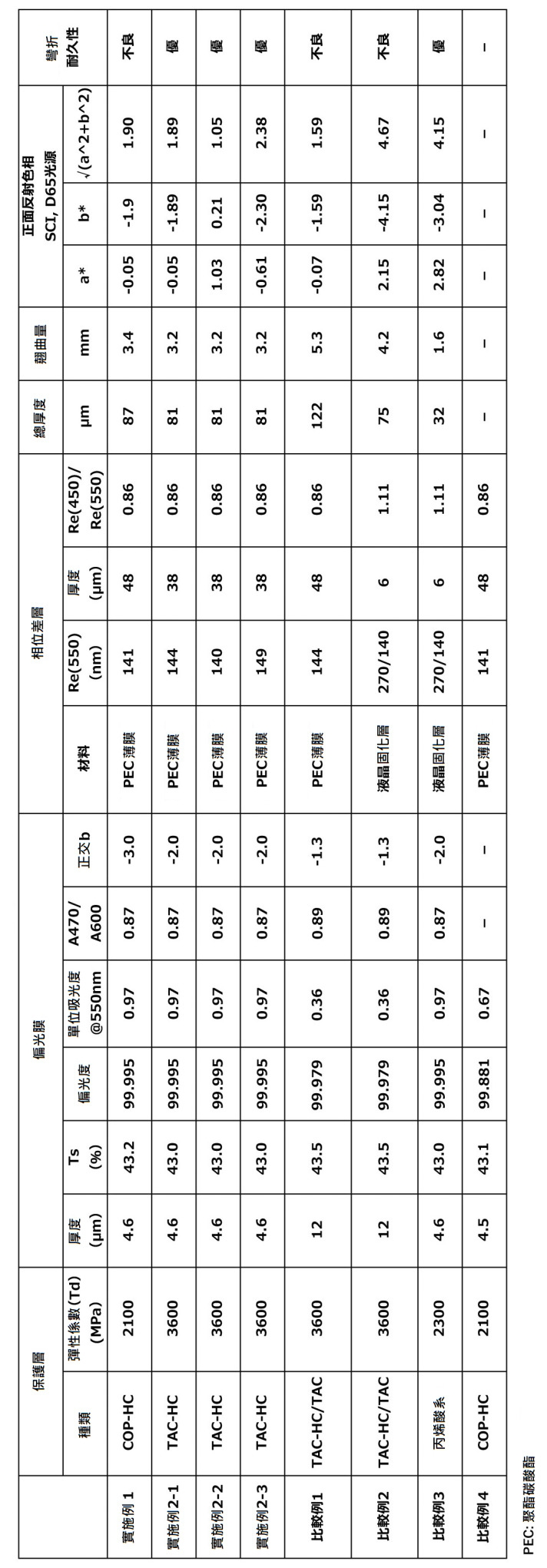
[評估] 比較實施例1與比較例1、2及4後明顯可知,以預定方法製出之偏光膜雖為薄型但顯示優異之光學特性。可知,藉由使用所述偏光膜,可獲得薄型且具優異之光學特性,並且加熱試驗後之翹曲經顯著抑制之(結果為處理性佳)附相位差層之偏光板。又,可知藉由組合由聚碳酸酯系樹脂(包含聚酯碳酸酯系樹脂)薄膜構成之相位差層來使用,可獲得優異之反射色相。並且,將聚碳酸酯系樹脂減薄至40μm以下,設附相位差層之偏光板之總厚度為85μm以下,並使用彈性係數為3000MPa以上之基材、較佳為使用TAC薄膜作為保護層,藉此可更提升彎折特性。另一方面,比較例3之附相位差層之偏光板為薄型且具優異之光學特性並且加熱試驗後之翹曲經顯著抑制,但反射色相大而在顯示特性之觀點上非為滿足者。[Evaluate] Comparing Example 1 with Comparative Examples 1, 2 and 4, it is obvious that the polarizing film produced by a predetermined method exhibits excellent optical properties although it is thin. It can be seen that by using the above-mentioned polarizing film, a polarizing plate with a retardation layer which is thin and has excellent optical characteristics and whose warping after the heating test is significantly suppressed (resulting in good handling properties) can be obtained. Moreover, it turned out that excellent reflection hue can be acquired by combining and using the retardation layer which consists of a polycarbonate resin (including polyester carbonate resin) film. In addition, the thickness of the polycarbonate resin is reduced to less than 40 μm, the total thickness of the polarizing plate with a retardation layer is less than 85 μm, and a substrate with an elastic modulus of 3000 MPa or more is used, preferably TAC film is used as a protective layer. Thereby, the bending characteristics can be further improved. On the other hand, the polarizing plate with a retardation layer of Comparative Example 3 is thin and has excellent optical characteristics, and the warpage after the heating test is significantly suppressed, but the reflection hue is large and is not satisfactory from the viewpoint of display characteristics.
產業上之可利用性 本發明之附相位差層之偏光板可適宜用作液晶顯示裝置、有機EL顯示裝置及無機EL顯示裝置用之圓偏光板。Industrial availability The polarizing plate with retardation layer of the present invention can be suitably used as a circular polarizing plate for liquid crystal display devices, organic EL display devices and inorganic EL display devices.
10:偏光板
11:偏光膜
12:第1保護層
13:第2保護層
20:相位差層(第1相位差層)
50:另一相位差層(第2相位差層)
60:導電層或附導電層之各向同性基材
100、101:附相位差層之偏光板
200:積層體
G1~G4:導輥
R1~R6:輸送輥
θ:角度10: polarizer
11: Polarizing film
12: The first protective layer
13: The second protective layer
20: Retardation layer (1st retardation layer)
50: Another retardation layer (the second retardation layer)
60: Conductive layer or isotropic substrate with
圖1係本發明之一實施形態之附相位差層之偏光板的概略截面圖。 圖2為本發明之另一實施形態之附相位差層之偏光板之概略截面圖。 圖3係顯示本發明附相位差層之偏光板所用偏光膜之製造方法中,利用加熱輥之乾燥收縮處理之一例的概略圖。Fig. 1 is a schematic cross-sectional view of a polarizing plate with a retardation layer according to an embodiment of the present invention. Fig. 2 is a schematic cross-sectional view of a polarizing plate with a retardation layer according to another embodiment of the present invention. Fig. 3 is a schematic view showing an example of drying shrinkage treatment using a heating roller in the method for producing a polarizing film used in a polarizing plate with a retardation layer according to the present invention.
10:偏光板 10: polarizer
11:偏光膜 11: Polarizing film
12:第1保護層 12: The first protective layer
13:第2保護層 13: The second protective layer
20:相位差層(第1相位差層) 20: Retardation layer (1st retardation layer)
100:附相位差層之偏光板 100: Polarizing plate with retardation layer
Claims (13)
Applications Claiming Priority (4)
| Application Number | Priority Date | Filing Date | Title |
|---|---|---|---|
| JP2018-194000 | 2018-10-15 | ||
| JP2018194000 | 2018-10-15 | ||
| JP2019-183608 | 2019-10-04 | ||
| JP2019183608A JP6890160B2 (en) | 2018-10-15 | 2019-10-04 | Polarizing plate with retardation layer and image display device using it |
Publications (2)
| Publication Number | Publication Date |
|---|---|
| TW202020031A TW202020031A (en) | 2020-06-01 |
| TWI801678B true TWI801678B (en) | 2023-05-11 |
Family
ID=70387295
Family Applications (1)
| Application Number | Title | Priority Date | Filing Date |
|---|---|---|---|
| TW108136721A TWI801678B (en) | 2018-10-15 | 2019-10-09 | Polarizing plate with retardation layer and image display device using same |
Country Status (4)
| Country | Link |
|---|---|
| JP (1) | JP6890160B2 (en) |
| KR (1) | KR102534630B1 (en) |
| CN (1) | CN112840252B (en) |
| TW (1) | TWI801678B (en) |
Families Citing this family (4)
| Publication number | Priority date | Publication date | Assignee | Title |
|---|---|---|---|---|
| JP7162037B2 (en) * | 2019-10-31 | 2022-10-27 | 住友化学株式会社 | image display device |
| JP7240363B2 (en) * | 2020-08-27 | 2023-03-15 | 日東電工株式会社 | Dyed triacetylcellulose film, polarizing plate using the film, method for producing polarizing plate, polarizing plate with retardation layer, image display device, and image adjustment method for image display device |
| KR20230172454A (en) | 2021-04-16 | 2023-12-22 | 닛토덴코 가부시키가이샤 | Circularly polarized film laminate with adhesive layer and image display device |
| JP2023128380A (en) | 2022-03-03 | 2023-09-14 | 日東電工株式会社 | Optical laminated body and image display device using the same |
Citations (3)
| Publication number | Priority date | Publication date | Assignee | Title |
|---|---|---|---|---|
| TW200930749A (en) * | 2007-12-13 | 2009-07-16 | Nitto Denko Corp | Process for producing polarizing element, polarizing element, polarizing plate, optical film, and image display |
| US20160147101A1 (en) * | 2013-07-22 | 2016-05-26 | Fujifilm Corporation | Liquid-crystal display device |
| JP2017054093A (en) * | 2015-07-22 | 2017-03-16 | 日東電工株式会社 | Polarizing plate having retardation layer and picture display unit |
Family Cites Families (23)
| Publication number | Priority date | Publication date | Assignee | Title |
|---|---|---|---|---|
| DE69923536T2 (en) | 1998-10-30 | 2006-03-30 | Teijin Ltd. | PHASE DIFFERENTIAL FILM AND THIS USING OPTICAL DEVICE |
| JP2008040251A (en) * | 2006-08-08 | 2008-02-21 | Nitto Denko Corp | Manufacturing method of polarizer, polarizer, polarizing plate, optical film, and image display device |
| JP5196651B2 (en) * | 2008-11-27 | 2013-05-15 | 日東電工株式会社 | Iodine polarizing film and method for producing the same |
| JP5923941B2 (en) * | 2011-11-18 | 2016-05-25 | 住友化学株式会社 | Polarizing film, circularly polarizing plate, and organic EL image display device using them |
| JP5528606B2 (en) * | 2012-06-21 | 2014-06-25 | 日東電工株式会社 | Polarizing plate and organic EL panel |
| JP2014010291A (en) * | 2012-06-29 | 2014-01-20 | Nitto Denko Corp | Circularly polarizing plate and display device |
| WO2014109299A1 (en) * | 2013-01-08 | 2014-07-17 | コニカミノルタ株式会社 | Cellulose acylate film, method for manufacturing same, polarization plate, and liquid-crystal display device |
| JP5615987B2 (en) * | 2013-02-07 | 2014-10-29 | 日東電工株式会社 | Optical laminate having polarizing film |
| KR20150004015A (en) * | 2013-07-02 | 2015-01-12 | 동우 화인켐 주식회사 | method of preparing a polarizer |
| CN104345371A (en) * | 2013-08-09 | 2015-02-11 | 住友化学株式会社 | Optical film |
| JP6150428B2 (en) * | 2013-08-12 | 2017-06-21 | 日東電工株式会社 | Polarizing film, optical functional film laminate including polarizing film, method for producing optical film laminate including polarizing film, and organic EL display device having polarizing film |
| KR101678275B1 (en) * | 2013-09-30 | 2016-11-21 | 주식회사 엘지화학 | Method for preparing polarizing plate near natural black color and polarizing plate prepared thereby |
| KR101705942B1 (en) * | 2014-03-17 | 2017-02-10 | 주식회사 엘지화학 | Retardation film, polarizing plate and display device comprising the same |
| JPWO2015152157A1 (en) * | 2014-03-31 | 2017-04-13 | 富士フイルム株式会社 | Polarizing plate, image display device, and liquid crystal display device |
| WO2015159929A1 (en) * | 2014-04-16 | 2015-10-22 | 三菱化学株式会社 | Retardation film, circularly-polarizing plate, and image-displaying device |
| US20160033699A1 (en) * | 2014-08-04 | 2016-02-04 | Nitto Denko Corporation | Polarizing plate |
| KR101702841B1 (en) * | 2014-09-01 | 2017-02-06 | 동우 화인켐 주식회사 | Method for monitoring defect in polaroid films |
| WO2016104741A1 (en) * | 2014-12-26 | 2016-06-30 | 富士フイルム株式会社 | Polarizer, polarizing plate, and image display device |
| JP6488135B2 (en) * | 2015-01-27 | 2019-03-20 | 日東電工株式会社 | Polarizing plate and manufacturing method of polarizing plate |
| KR101663698B1 (en) * | 2015-03-16 | 2016-10-07 | 동우 화인켐 주식회사 | Preparing method for polarizer |
| JP6144731B2 (en) * | 2015-07-22 | 2017-06-07 | 住友化学株式会社 | Polarizer |
| JP6143917B2 (en) * | 2015-08-18 | 2017-06-07 | 住友化学株式会社 | Convex-side polarizing plate for curved image display panel |
| JP6453746B2 (en) * | 2015-12-02 | 2019-01-16 | 日東電工株式会社 | Elongated optical laminate and image display device |
-
2019
- 2019-10-04 JP JP2019183608A patent/JP6890160B2/en active Active
- 2019-10-08 CN CN201980067871.6A patent/CN112840252B/en active Active
- 2019-10-08 KR KR1020217011095A patent/KR102534630B1/en active IP Right Grant
- 2019-10-09 TW TW108136721A patent/TWI801678B/en active
Patent Citations (3)
| Publication number | Priority date | Publication date | Assignee | Title |
|---|---|---|---|---|
| TW200930749A (en) * | 2007-12-13 | 2009-07-16 | Nitto Denko Corp | Process for producing polarizing element, polarizing element, polarizing plate, optical film, and image display |
| US20160147101A1 (en) * | 2013-07-22 | 2016-05-26 | Fujifilm Corporation | Liquid-crystal display device |
| JP2017054093A (en) * | 2015-07-22 | 2017-03-16 | 日東電工株式会社 | Polarizing plate having retardation layer and picture display unit |
Also Published As
| Publication number | Publication date |
|---|---|
| CN112840252B (en) | 2022-08-02 |
| KR102534630B1 (en) | 2023-05-26 |
| KR20210071998A (en) | 2021-06-16 |
| JP6890160B2 (en) | 2021-06-18 |
| TW202020031A (en) | 2020-06-01 |
| CN112840252A (en) | 2021-05-25 |
| JP2020064290A (en) | 2020-04-23 |
Similar Documents
| Publication | Publication Date | Title |
|---|---|---|
| TWI827699B (en) | Polarizing plate with retardation layer and image display device using the same | |
| TWI801678B (en) | Polarizing plate with retardation layer and image display device using same | |
| JP6999059B2 (en) | Polarizing plate with retardation layer and image display device using it | |
| TWI824033B (en) | Polarizing plate with retardation layer and image display device using the same | |
| TWI777075B (en) | Polarizing plate with retardation layer and image display device using the same | |
| TWI783183B (en) | Polarizing plate with retardation layer and image display device using same | |
| TWI819119B (en) | Method for manufacturing polarizing plate with retardation layer | |
| TWI796273B (en) | Polarizing plate with retardation layer and image display device using same | |
| TWI833820B (en) | Polarizing plate with retardation layer and image display device using the same | |
| TW202104390A (en) | Polarizing plate having phase difference layer and image display device using same | |
| TW202026152A (en) | Polarizing plate with retardation layer and image display device using same | |
| TW202040171A (en) | Polarizing plate with retardation layer and image display device using same | |
| TW202036049A (en) | Polarizing plate with retardation layer and image display device using same | |
| WO2020080173A1 (en) | Polarizing plate with phase difference layer, and image display device using this | |
| WO2020080171A1 (en) | Polarizing plate with phase difference layer, and image display device using this | |
| WO2020080188A1 (en) | Polarizing plate with retardation layer and image display device using same | |
| WO2020080185A1 (en) | Polarizing plate with retardation layer and image display device using same |