TWI768614B - Projection system and method for selecting number of images captured used for image blending - Google Patents
Projection system and method for selecting number of images captured used for image blending Download PDFInfo
- Publication number
- TWI768614B TWI768614B TW109145901A TW109145901A TWI768614B TW I768614 B TWI768614 B TW I768614B TW 109145901 A TW109145901 A TW 109145901A TW 109145901 A TW109145901 A TW 109145901A TW I768614 B TWI768614 B TW I768614B
- Authority
- TW
- Taiwan
- Prior art keywords
- devices
- image
- projection
- image capturing
- capture
- Prior art date
Links
- 238000000034 method Methods 0.000 title claims abstract description 22
- 238000002156 mixing Methods 0.000 title abstract description 7
- 238000003384 imaging method Methods 0.000 claims description 29
- 230000002159 abnormal effect Effects 0.000 claims description 7
- 230000005856 abnormality Effects 0.000 claims 2
- 230000009849 deactivation Effects 0.000 claims 1
- 230000004927 fusion Effects 0.000 abstract description 14
- 238000004364 calculation method Methods 0.000 abstract description 7
- 230000007613 environmental effect Effects 0.000 abstract description 5
- 238000010586 diagram Methods 0.000 description 6
- 238000005516 engineering process Methods 0.000 description 2
- 239000012634 fragment Substances 0.000 description 2
- 238000004458 analytical method Methods 0.000 description 1
- 230000000694 effects Effects 0.000 description 1
- 230000001788 irregular Effects 0.000 description 1
- 238000005070 sampling Methods 0.000 description 1
- 230000005236 sound signal Effects 0.000 description 1
Images


Classifications
-
- H—ELECTRICITY
- H04—ELECTRIC COMMUNICATION TECHNIQUE
- H04N—PICTORIAL COMMUNICATION, e.g. TELEVISION
- H04N23/00—Cameras or camera modules comprising electronic image sensors; Control thereof
- H04N23/60—Control of cameras or camera modules
- H04N23/64—Computer-aided capture of images, e.g. transfer from script file into camera, check of taken image quality, advice or proposal for image composition or decision on when to take image
-
- G—PHYSICS
- G06—COMPUTING; CALCULATING OR COUNTING
- G06T—IMAGE DATA PROCESSING OR GENERATION, IN GENERAL
- G06T5/00—Image enhancement or restoration
- G06T5/50—Image enhancement or restoration by the use of more than one image, e.g. averaging, subtraction
-
- G—PHYSICS
- G03—PHOTOGRAPHY; CINEMATOGRAPHY; ANALOGOUS TECHNIQUES USING WAVES OTHER THAN OPTICAL WAVES; ELECTROGRAPHY; HOLOGRAPHY
- G03B—APPARATUS OR ARRANGEMENTS FOR TAKING PHOTOGRAPHS OR FOR PROJECTING OR VIEWING THEM; APPARATUS OR ARRANGEMENTS EMPLOYING ANALOGOUS TECHNIQUES USING WAVES OTHER THAN OPTICAL WAVES; ACCESSORIES THEREFOR
- G03B37/00—Panoramic or wide-screen photography; Photographing extended surfaces, e.g. for surveying; Photographing internal surfaces, e.g. of pipe
- G03B37/04—Panoramic or wide-screen photography; Photographing extended surfaces, e.g. for surveying; Photographing internal surfaces, e.g. of pipe with cameras or projectors providing touching or overlapping fields of view
-
- G—PHYSICS
- G06—COMPUTING; CALCULATING OR COUNTING
- G06F—ELECTRIC DIGITAL DATA PROCESSING
- G06F18/00—Pattern recognition
- G06F18/20—Analysing
- G06F18/25—Fusion techniques
- G06F18/251—Fusion techniques of input or preprocessed data
-
- G—PHYSICS
- G06—COMPUTING; CALCULATING OR COUNTING
- G06T—IMAGE DATA PROCESSING OR GENERATION, IN GENERAL
- G06T7/00—Image analysis
- G06T7/70—Determining position or orientation of objects or cameras
-
- G—PHYSICS
- G06—COMPUTING; CALCULATING OR COUNTING
- G06V—IMAGE OR VIDEO RECOGNITION OR UNDERSTANDING
- G06V10/00—Arrangements for image or video recognition or understanding
- G06V10/10—Image acquisition
- G06V10/12—Details of acquisition arrangements; Constructional details thereof
- G06V10/14—Optical characteristics of the device performing the acquisition or on the illumination arrangements
- G06V10/145—Illumination specially adapted for pattern recognition, e.g. using gratings
-
- H—ELECTRICITY
- H04—ELECTRIC COMMUNICATION TECHNIQUE
- H04N—PICTORIAL COMMUNICATION, e.g. TELEVISION
- H04N23/00—Cameras or camera modules comprising electronic image sensors; Control thereof
- H04N23/60—Control of cameras or camera modules
-
- H—ELECTRICITY
- H04—ELECTRIC COMMUNICATION TECHNIQUE
- H04N—PICTORIAL COMMUNICATION, e.g. TELEVISION
- H04N23/00—Cameras or camera modules comprising electronic image sensors; Control thereof
- H04N23/60—Control of cameras or camera modules
- H04N23/667—Camera operation mode switching, e.g. between still and video, sport and normal or high- and low-resolution modes
-
- H—ELECTRICITY
- H04—ELECTRIC COMMUNICATION TECHNIQUE
- H04N—PICTORIAL COMMUNICATION, e.g. TELEVISION
- H04N23/00—Cameras or camera modules comprising electronic image sensors; Control thereof
- H04N23/80—Camera processing pipelines; Components thereof
-
- H—ELECTRICITY
- H04—ELECTRIC COMMUNICATION TECHNIQUE
- H04N—PICTORIAL COMMUNICATION, e.g. TELEVISION
- H04N23/00—Cameras or camera modules comprising electronic image sensors; Control thereof
- H04N23/90—Arrangement of cameras or camera modules, e.g. multiple cameras in TV studios or sports stadiums
-
- H—ELECTRICITY
- H04—ELECTRIC COMMUNICATION TECHNIQUE
- H04N—PICTORIAL COMMUNICATION, e.g. TELEVISION
- H04N9/00—Details of colour television systems
- H04N9/12—Picture reproducers
- H04N9/31—Projection devices for colour picture display, e.g. using electronic spatial light modulators [ESLM]
- H04N9/3141—Constructional details thereof
- H04N9/3147—Multi-projection systems
-
- H—ELECTRICITY
- H04—ELECTRIC COMMUNICATION TECHNIQUE
- H04N—PICTORIAL COMMUNICATION, e.g. TELEVISION
- H04N9/00—Details of colour television systems
- H04N9/12—Picture reproducers
- H04N9/31—Projection devices for colour picture display, e.g. using electronic spatial light modulators [ESLM]
- H04N9/3179—Video signal processing therefor
-
- H—ELECTRICITY
- H04—ELECTRIC COMMUNICATION TECHNIQUE
- H04N—PICTORIAL COMMUNICATION, e.g. TELEVISION
- H04N9/00—Details of colour television systems
- H04N9/12—Picture reproducers
- H04N9/31—Projection devices for colour picture display, e.g. using electronic spatial light modulators [ESLM]
- H04N9/3191—Testing thereof
- H04N9/3194—Testing thereof including sensor feedback
-
- G—PHYSICS
- G06—COMPUTING; CALCULATING OR COUNTING
- G06T—IMAGE DATA PROCESSING OR GENERATION, IN GENERAL
- G06T2207/00—Indexing scheme for image analysis or image enhancement
- G06T2207/20—Special algorithmic details
- G06T2207/20212—Image combination
- G06T2207/20221—Image fusion; Image merging
-
- G—PHYSICS
- G06—COMPUTING; CALCULATING OR COUNTING
- G06T—IMAGE DATA PROCESSING OR GENERATION, IN GENERAL
- G06T2207/00—Indexing scheme for image analysis or image enhancement
- G06T2207/30—Subject of image; Context of image processing
- G06T2207/30168—Image quality inspection
Abstract
Description
本發明是有關於一種投影系統及方法,且特別是有關於一種投影系統以及用於影像拼接(image blending)的取像數量選擇方法。The present invention relates to a projection system and method, and more particularly, to a projection system and a method for selecting the number of images taken for image blending.
投影拼接工程為整合多台投影機,使投影畫面融合於延伸壁面、環狀、弧狀、不規則壁面等展示區。投影機的選擇最為重要,由於沒有邊緣融合器,在兩台投影機的投影範圍相交的地方,就會出現畫面重疊的問題,導致重疊的區域亮度增強,信號模糊。邊緣融合技術就是將一組投影機投射出的畫面進行邊緣重疊,並通過融合技術顯示出一個沒有縫隙,且更加明亮、解析度更高的整幅畫面,使得畫面的效果就好像是一台投影機投射的畫質。為了實現自動拼接,借助相機來拍攝投影影像,以利用投影影像來執行自動拼接融合所需的影像辨識與計算。The projection splicing project is to integrate multiple projectors, so that the projection images can be integrated into the display areas such as extended walls, annular, arc-shaped and irregular walls. The choice of the projector is the most important, because there is no edge fusion device, where the projection ranges of the two projectors intersect, there will be a problem of overlapping images, resulting in increased brightness in the overlapping area and blurred signals. Edge fusion technology is to overlap the edges of the pictures projected by a group of projectors, and display a whole picture with no gaps, brighter and higher resolution through fusion technology, so that the effect of the picture is like a projection. projector image quality. In order to realize automatic stitching, a camera is used to shoot a projected image, and the projected image is used to perform image recognition and calculation required for automatic stitching and fusion.
“先前技術”段落只是用來幫助了解本案內容,因此在“先前技術”段落所揭露的內容可能包含一些沒有構成所屬技術領域中具有通常知識者所知道的習知技術。在“先前技術”段落所揭露的內容,不代表該內容或者本案一個或多個實施例所要解決的問題,在本案申請前已被所屬技術領域中具有通常知識者所知曉或認知。The "prior art" paragraph is only used to help understand the content of the present case, so the content disclosed in the "prior art" paragraph may contain some prior art that does not constitute the prior art known to those with ordinary knowledge in the art. The content disclosed in the "Prior Art" paragraph does not represent the content or the problem to be solved by one or more embodiments of the present application, and has been known or recognized by those with ordinary knowledge in the technical field before the application of the present application.
本發明提供一種投影系統以及用於影像拼接的取像數選擇方法,可避免在執行自動拼接融合所需的影像辨識與計算時,環境影響或影像擷取裝置故障導致無法維護拼接融合的問題。The present invention provides a projection system and a method for selecting the number of captured images for image splicing, which can avoid the problem that the splicing and fusion cannot be maintained due to environmental influences or failure of the image capture device when performing image recognition and calculation required for automatic splicing and fusion.
本發明的投影系統,包括:多個投影裝置、多個影像擷取裝置以及處理器。處理器耦接至投影裝置以及影像擷取裝置。處理器經配置以逐一驅使所述投影裝置投射圖案,驅使所述影像擷取裝置來拍攝各投影裝置所投射的圖案,藉此獲得對應所述影像擷取裝置的多個取像結果,以及基於所述取像結果自所述影像擷取裝置中選擇至少一者作為影像拼接的取像來源。The projection system of the present invention includes a plurality of projection devices, a plurality of image capture devices and a processor. The processor is coupled to the projection device and the image capture device. The processor is configured to drive the projection devices to project patterns one by one, drive the image capture devices to photograph the patterns projected by each projection device, thereby obtaining a plurality of image capture results corresponding to the image capture devices, and based on The image acquisition result selects at least one image acquisition source from the image acquisition device as an image acquisition source for image stitching.
在本發明的一實施例中,所述處理器經配置以在其中一個投影裝置投射圖案之後,驅使影像擷取裝置分別拍攝或同時拍攝所投射的圖案。In an embodiment of the present invention, the processor is configured to, after one of the projection devices projects the pattern, drive the image capture devices to capture the projected patterns separately or simultaneously.
在本發明的一實施例中,所述圖案包括至少一格點。所述處理器經配置以識別各取像結果中所包括的格點的格點數量以及格點所在的一格點位置,以及基於格點數量與格點位置,自影像擷取裝置中選擇至少一者來作為影像拼接的取像來源,其中所選擇至少一個影像擷取裝置的拍攝範圍涵蓋最多的至少一格點。In an embodiment of the present invention, the pattern includes at least one lattice point. The processor is configured to identify the number of grid points and a grid point position at which the grid points are included in each imaging result, and based on the number of grid points and the grid point positions, select at least one of the image capture devices. One is used as an image capture source for image stitching, wherein the shooting range of the selected at least one image capture device covers the most at least one grid point.
在本發明的一實施例中,所述處理器經配置以基於每個取像結果中所包括的格點數量、至少一格點所在的格點位置以及取像品質,自選擇至少一個影像擷取裝置來作為影像拼接的取像來源。In an embodiment of the present invention, the processor is configured to self-select at least one image capture based on the number of grid points included in each imaging result, the grid point position where at least one grid point is located, and the imaging quality The device is used as the image acquisition source for image stitching.
在本發明的一實施例中,所述處理器經配置以在判定作為取像來源中的至少一個影像擷取裝置的取像異常時,停用被判定為取像異常的至少一個影像擷取裝置,而自其他未被選擇的影像擷取裝置中選擇至少一者,來更新取像來源。In an embodiment of the present invention, the processor is configured to disable at least one image capture that is determined to be abnormal in the capture when it is determined that the capture of at least one image capture device in the capture source is abnormal device, and select at least one image capturing device from other unselected image capturing devices to update the image capturing source.
在本發明的一實施例中,所述處理器經配置以在判定更新後的取像來源的拍攝範圍無法涵蓋所述投影裝置的投影範圍時,發出警示通知。In an embodiment of the present invention, the processor is configured to issue a warning notification when it is determined that the shooting range of the updated imaging source cannot cover the projection range of the projection device.
在本發明的一實施例中,所述投影裝置的數量為至少兩個,所述影像擷取裝置的數量為至少兩個,所述投影機裝置的數量與所述影像擷取裝置的數量可以相同或不同。In an embodiment of the present invention, the number of the projection devices is at least two, the number of the image capture devices is at least two, and the number of the projector devices and the number of the image capture devices can be same or different.
在本發明的一實施例中,所述影像擷取裝置的其中一者設置在所述投影裝置的其中一者上In an embodiment of the present invention, one of the image capturing devices is disposed on one of the projection devices
本發明的用於影像拼接的取像數量選擇方法,包括:逐一驅使多個投影裝置投射一圖案;驅使多個影像擷取裝置來拍攝各投影裝置所投射的圖案,藉此獲得對應這些影像擷取裝置的多個取像結果;以及基於這些取像結果自所述影像擷取裝置中選擇至少一者作為影像拼接的取像來源。The method for selecting the number of images for image splicing of the present invention includes: driving a plurality of projection devices one by one to project a pattern; and selecting at least one image capturing device from the image capturing device as an image capturing source for image stitching based on the image capturing results.
基於上述,本發明可以使得投射出的圖像經由影像擷取裝置取像的數量降低,進而提升取像流程速度,並且可避免在執行自動拼接融合所需的影像辨識與計算時,環境影響或影像擷取裝置故障導致無法維護拼接融合的問題。Based on the above, the present invention can reduce the number of projected images captured by the image capture device, thereby increasing the speed of the image capturing process, and can avoid environmental influences or environmental impacts when performing image recognition and calculation required for automatic splicing and fusion. The problem of unmaintainable stitching fusion caused by the failure of the image capture device.
圖1是依照本發明一實施例的投影系統的方塊圖。請參照圖1,本實施例的投影系統包括M個投影裝置110-1~110-M、N個影像擷取裝置120-1~120-N以及處理器130。在此,並不限制投影裝置(projection device)與影像擷取裝置(image capturing device)兩者的數量,只要存在至少兩個投影裝置以及至少兩個影像擷取裝置即可,而投影裝置的數量M與影像擷取裝置的數量N可以相同或不同。FIG. 1 is a block diagram of a projection system according to an embodiment of the present invention. Referring to FIG. 1 , the projection system of this embodiment includes M projection devices 110 - 1 to 110 -M, N image capture devices 120 - 1 to 120 -N, and a
在設置上,可將影像擷取裝置120-1~120-N分別安裝至每一個投影裝置110-1~110-M上。例如,一個投影裝置上設置一個影像擷取裝置。而處理器130例如安裝在一獨立的電子裝置中,透過有線或無線的方式耦接至投影裝置110-1~110-M以及影像擷取裝置120-1~120-N,藉此來驅動投影裝置110-1~110-M及影像擷取裝置120-1~120-N進行作動,並在進行影像辨識分析之後,調整投影裝置110-1~110-M的參數。In terms of setting, the image capturing devices 120-1 to 120-N can be respectively installed on each of the projection devices 110-1 to 110-M. For example, a projection device is provided with an image capture device. The
處理器130例如為具有中央處理單元(Central Processing Unit,CPU)、圖像處理單元(Graphic Processing Unit,GPU)、物理處理單元(Physics Processing Unit,PPU)、可程式化之微處理器(Microprocessor)、嵌入式控制晶片、數位訊號處理器(Digital Signal Processor,DSP)、特殊應用積體電路(Application Specific Integrated Circuits,ASIC)的裝置或其他類似裝置。在一實施例中,處理器130可為影像拼接處理裝置。而所述電子裝置中還包括儲存裝置,其可由任意型式的固定式或可移動式隨機存取記憶體、唯讀記憶體、快閃記憶體、安全數位卡、硬碟或其他類似裝置或這些裝置的組合來實現。在儲存裝置中儲存一或多個程式碼片段,而由處理器130來執行所述程式碼片段來完成下述用於影像拼接的取像數量選擇方法。The
圖2是依照本發明一實施例的用於影像拼接的取像數量選擇方法的流程圖。請同時參照圖1及圖2,在步驟S205中,透過處理器130來逐一驅使多個投影裝置110-1~110-M投射一圖案(pattern)。所述圖案例如是在左右側具有多個格點。FIG. 2 is a flowchart of a method for selecting the number of images taken for image stitching according to an embodiment of the present invention. Referring to FIG. 1 and FIG. 2 simultaneously, in step S205 , the
並且,在步驟S210中,透過處理器130驅使多個影像擷取裝置120-1~120-N來拍攝各個投影裝置110-1~110-M所投射的圖案,藉此獲得對應各個影像擷取裝置120-1~120-N的取像結果。在此,可在其中一個投影裝置投射圖案之後,處理器130驅使影像擷取裝置120-1~120-N分別拍攝或同時拍攝所投射的圖案。In addition, in step S210, the
在步驟S215中,處理器130基於這些取像結果自影像擷取裝置120-1~120-N中選擇至少一者作為影像拼接的取像來源。處理器130可識別各取像結果中所包括的格點的格點數量以及各格點所在的格點位置,以及基於格點數量與格點位置,自影像擷取裝置120-1~120-N中選擇至少一者來作為影像拼接的取像來源。在此,所選擇的影像擷取裝置的拍攝範圍涵蓋最多的格點。In step S215 , the
由於全部的投影裝置110-1~110-N皆投射圖案的情況下,會造成圖案重疊的問題,故,處理器130一次驅使一個投影裝置來投射圖案,並且在每一次投射圖案時由至少一個影像擷取裝置來進行取像。底下再舉一例來說明取像順序。值得一提的是,各個投影裝置投射圖案的順序可由處理器130決定或使用者設定,並不一定是由多個投影裝置設置順序依序投射。Since all the projection devices 110-1 to 110-N are projecting patterns, the problem of pattern overlapping will be caused. Therefore, the
圖3是依照本發明一實施例的取像結果的獲得方法的流程圖。請參照圖3,在步驟S305中,驅使第i個投影裝置投射圖案。在此,i的初始值為1。接著,在步驟S310中,驅使第j個影像擷取裝置拍攝所投射的圖案。在此,j的初始值為1。並且,在步驟S315中,i=i+1,以在後續驅使下一個投影裝置來投射圖案。接著在步驟S320中,判斷是否全部的投影裝置皆投射完畢。例如,在設有M個投影裝置的情況下,判斷i是否大於M。若尚有投影裝置未投射完畢(i未大於M),則返回步驟S305;若全部的投影裝置皆投射完畢(i大於M),在步驟S325中,j=j+1,以在後續驅使下一個影像擷取裝置來拍攝所投射的圖案。FIG. 3 is a flowchart of a method for obtaining an imaging result according to an embodiment of the present invention. Referring to FIG. 3, in step S305, the i-th projection device is driven to project a pattern. Here, the initial value of i is 1. Next, in step S310, the j-th image capturing device is driven to capture the projected pattern. Here, the initial value of j is 1. And, in step S315, i=i+1, so as to drive the next projection device to project the pattern subsequently. Next, in step S320, it is determined whether all the projection devices have completed the projection. For example, when there are M projection devices, it is determined whether i is larger than M. If there are still projection devices that have not finished projecting (i is not greater than M), then return to step S305; if all projection devices have finished projecting (i is greater than M), in step S325, j=j+1, so that under subsequent driving An image capture device captures the projected pattern.
接著,在步驟S330中,判斷是否全部的影像擷取裝置皆取像完畢。例如,在設有N個影像擷取裝置的情況下,判斷j是否大於N。若尚有影像擷取裝置未取像完畢(j未大於M),返回步驟S305。若全部的影像擷取裝置皆取像完畢(j大於M),在步驟S335中,獲得取像結果。Next, in step S330, it is determined whether all the image capturing devices have completed capturing images. For example, when there are N image capturing devices, it is determined whether j is greater than N. If there are still image capturing devices that have not finished capturing images (j is not greater than M), return to step S305 . If all the image capturing devices have completed capturing images (j is greater than M), in step S335, the capturing results are obtained.
例如,首先處理器130驅使投影裝置110-1投射圖案,並且驅使影像擷取裝置120-1來進行取像。接著,驅使投影裝置110-2投射圖案,並且驅使影像擷取裝置120-1來進行取像。以此類推,驅使投影裝置110-M投射圖案,並且驅使影像擷取裝置120-1來進行取像。即,影像擷取裝置120-1分別對投影裝置110-1~110-M所投射的圖案進行取像。之後,重新驅使投影裝置110-1~110-M投射圖案,而由影像擷取裝置120-2分別對投影裝置110-1~110-M所投射的圖案進行取像。以此類推,直到影像擷取裝置120-N分別對投影裝置110-1~110-M所投射的圖案進行取像。For example, first, the
在其他實施例中,也可以在每一次由一個投影裝置投射圖案之後,同時驅使全部的影像擷取裝置120-1~120-N進行取像。在另一實施例中,投影裝置投射圖案與影像擷取裝置進行取像之間的順序可根據實際狀況而做不同設計。例如,可驅使一部份的投影裝置投射圖案後,再驅使一部份的影像擷取裝置進行取像,接著,驅使另一部份的投影裝置投射圖案後再驅使另一部份的影像擷取裝置進行取像。In other embodiments, all the image capturing devices 120 - 1 to 120 -N may be simultaneously driven to capture images after each time the pattern is projected by one projection device. In another embodiment, the sequence between the pattern projected by the projection device and the image captured by the image capture device can be designed differently according to the actual situation. For example, after driving a part of the projection device to project a pattern, then driving a part of the image capture device to capture an image, then driving another part of the projection device to project the pattern, and then driving another part of the image capture device Take the device to take the image.
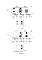
圖4A~圖4I是依照本發明一實施例的取像結果的示意圖。在本實施例中,以3個投影裝置110-1~110-3以及3個影像擷取裝置120-1~120-3為例來進行說明,並以在四個角落設置4個格點來作為投射的圖案,投射的圖案並不以此為限。在此,基於投影裝置110-1~110-3設置的位置,其所投射出來的投影影像(411~413、421~423、431~433、441~443、451~453、461~463、471~473、481~483、491~493)會有重疊部分(如圖4A~圖4I中陰影區塊所示)。據此,在全部投影裝置投射圖案的情況下,會造成圖案重疊的問題。4A to 4I are schematic diagrams of imaging results according to an embodiment of the present invention. In the present embodiment, three projection devices 110-1 to 110-3 and three image capture devices 120-1 to 120-3 are used as examples for description, and four grid points are set at four corners. As the projected pattern, the projected pattern is not limited to this. Here, based on the positions where the projection devices 110-1 to 110-3 are installed, the projected images (411 to 413, 421 to 423, 431 to 433, 441 to 443, 451 to 453, 461 to 463, 471 ~473, 481~483, 491~493) will have overlapping parts (shown as shaded blocks in Figure 4A ~ Figure 4I). Accordingly, when all the projection devices project the pattern, the problem of pattern overlapping will be caused.
故,在本實施例中設置為:處理器130一次驅使一個投影裝置來投射所述圖案,其投射順序例如依序為投影裝置110-1、投影裝置110-2、投影裝置110-3,並且在每一次進行投影時由一個影像擷取裝置來進行取像。而每一個影像擷取裝置120-1~120-3會皆會分別對投影裝置110-1~110-3進行取像來獲得取像結果A1~A9。故,以3個投影裝置以及3個影像擷取裝置而言,最終會獲得9(3×3)個取像結果。Therefore, in this embodiment, the
首先,參照圖4A~圖4C,處理器130驅使影像擷取裝置120-1分別對投影裝置110-1~110-3所投射的圖案進行取像。接著,參照圖4D~圖4F,驅使影像擷取裝置120-2分別對投影裝置110-1~110-3所投射的圖案進行取像。之後,參照圖4G~圖4I,驅使影像擷取裝置120-3分別對投影裝置110-1~110-3所投射的圖案進行取像。First, referring to FIGS. 4A to 4C , the
在圖4A中,處理器130驅使投影裝置110-1來投射圖案,藉此獲得投影影像411。此時,由於投影裝置110-2、110-3並未投射圖案,故,兩者對應的投影影像412、413為空白。並且,處理器130驅使影像擷取裝置120-1進行取像以獲得取像結果A1。在圖4B中,處理器130驅使投影裝置110-2來投射圖案,藉此獲得投影影像422。此時,由於投影裝置110-1、110-3並未投射圖案,故,兩者對應的投影影像421、423為空白。並且,處理器130驅使影像擷取裝置120-1進行取像以獲得取像結果A2。在圖4C中,處理器130驅使投影裝置110-3來投射圖案,藉此獲得投影影像433。此時,由於投影裝置110-1、110-2並未投射圖案,故,兩者對應的投影影像431、432為空白。並且,處理器130驅使影像擷取裝置120-1進行取像以獲得取像結果A3。In FIG. 4A , the
在圖4D中,處理器130驅使投影裝置110-1來投射圖案,藉此獲得投影影像441。此時,由於投影裝置110-2、110-3並未投射圖案,故,兩者對應的投影影像442、443為空白。並且,處理器130驅使影像擷取裝置120-2進行取像以獲得取像結果A4。在圖4E中,處理器130驅使投影裝置110-2來投射圖案,藉此獲得投影影像452。此時,由於投影裝置110-1、110-3並未投射圖案,故,兩者對應的投影影像451、453為空白。並且,處理器130驅使影像擷取裝置120-2進行取像以獲得取像結果A5。在圖4F中,處理器130驅使投影裝置110-3來投射圖案,藉此獲得投影影像463。此時,由於投影裝置110-1、110-2並未投射圖案,故,兩者對應的投影影像461、462為空白。並且,處理器130驅使影像擷取裝置120-2進行取像以獲得取像結果A6。In FIG. 4D , the
在圖4G中,處理器130驅使投影裝置110-1來投射圖案,藉此獲得投影影像471。此時,由於投影裝置110-2、110-3並未投射圖案,故,兩者對應的投影影像472、473為空白。並且,處理器130驅使影像擷取裝置120-3進行取像以獲得取像結果A7。在圖4H中,處理器130驅使投影裝置110-2來投射圖案,藉此獲得投影影像482。此時,由於投影裝置110-1、110-3並未投射圖案,故,兩者對應的投影影像481、483為空白。並且,處理器130驅使影像擷取裝置120-3進行取像以獲得取像結果A8。在圖4I中,處理器130驅使投影裝置110-3來投射圖案,藉此獲得投影影像493。此時,由於投影裝置110-1、110-2並未投射圖案,故,兩者對應的投影影像491、492為空白。並且,處理器130驅使影像擷取裝置120-3進行取像以獲得取像結果A9。In FIG. 4G , the
在獲得取像結果A1~A9之後,處理器130基於取像結果A1~A9,識別取像結果A1~A9中所包括的格點的格點數量以及格點所在的格點位置。進而,處理器130基於取像結果A1~A9中的格點位置來判斷各影像擷取裝置120-1~120-3的拍攝範圍涵蓋了哪些投影裝置的投影範圍。藉此,針對各影像擷取裝置120-1~120-3的拍攝範圍將所涵蓋的格點數量與投影範圍整理如表1。After obtaining the imaging results A1 ˜ A9 , the
表1
參照表1,可分別基於取像結果A1~A3、取像結果A4~A6、取像結果A7~A9,來識別影像擷取裝置120-1、120-2、120-3的拍攝範圍所涵蓋的格點數量以及投影範圍。Referring to Table 1, based on the imaging results A1-A3, the imaging results A4-A6, and the imaging results A7-A9, it is possible to identify the imaging ranges covered by the image capturing devices 120-1, 120-2, and 120-3. The number of grid points and the projection range.
基此,處理器130基於各影像擷取裝置120-1~120-3的拍攝範圍所涵蓋的格點數量以及格點位置,自影像擷取裝置120-1~120-3中來選擇作為影像拼接的取像來源。並且,將其他未被選取的影像擷取裝置作為備用的取像來源。Based on this, the
舉例來說,以圖4A~圖4I所投射的圖案(包括4個格點)而言,倘若其中一個影像擷取裝置所涵蓋的格點數量等於12,其表示對應於3個投影裝置110-1~110-3的每一個取像結果皆具有4個格點,故,便可只用所述一個影像擷取裝置來作為取像來源。For example, for the patterns projected in FIGS. 4A to 4I (including 4 grid points), if the number of grid points covered by one of the image capture devices is equal to 12, it means that it corresponds to 3 projection devices 110- Each of the
倘若並不存在所涵蓋的格點數量等於12的影像擷取裝置,則選擇所涵蓋的格點數量最大的影像擷取裝置來作為取像來源,並且確認取像來源的拍攝範圍可涵蓋所有投影裝置的投影範圍。倘若取像來源的拍攝範圍未涵蓋所有投影裝置的投影範圍,則再進一步選擇具有格點數量第二多的影像擷取裝置來作為取像來源。以圖4A~圖4I所示的實施例而言(參照表1),選擇影像擷取裝置120-2、120-3(其所涵蓋的格點數量最多)來作為取像來源,且影像擷取裝置120-2、120-3的拍攝範圍可涵蓋所有投影裝置110-1~110-3的投影範圍。If there is no image capture device with the number of covered grid points equal to 12, select the image capture device with the largest number of covered grid points as the imaging source, and confirm that the shooting range of the imaging source can cover all projections. The projection range of the device. If the shooting range of the image capturing source does not cover the projection range of all the projection devices, the image capturing device with the second largest number of grid points is further selected as the image capturing source. For the embodiment shown in FIGS. 4A to 4I (refer to Table 1), the image capturing devices 120-2 and 120-3 (which cover the largest number of grid points) are selected as image capturing sources, and the image capturing devices 120-2 and 120-3 are selected as image capturing sources. The shooting ranges of the acquisition devices 120-2 and 120-3 may cover the projection ranges of all the projection devices 110-1 to 110-3.
另外,處理器130還可基於每個取像結果中所包括的格點數量、格點位置以及取像品質,來決定影像拼接的取像來源。例如,假設基於取像結果來找出格點數量最大的影像擷取裝置包括A、B、C三者,且影像擷取裝置A、B的拍攝範圍涵蓋所有投影裝置的投影範圍,影像擷取裝置A、C的拍攝範圍亦涵蓋所有投影裝置的投影範圍,則可進一步根據影像擷取裝置B、C的取像品質來決定取像來源為影像擷取裝置A、B或影像擷取裝置A、C。In addition, the
另外,當處理器130判定作為取像來源中的至少一個影像擷取裝置取像異常時,停用被判定為取像異常的影像擷取裝置,而自其他未被選擇的影像擷取裝置中選擇至少一者,來更新取像來源。優先選擇能夠涵蓋所有投影裝置的投影範圍的影像擷取裝置,以使更新後的取像來源的拍攝範圍涵蓋所有投影裝置的投影範圍。In addition, when the
圖5A及圖5B是依照本發明一實施例的啟用備用裝置的示意圖。在本實施例中,以3個投影裝置110-1~110-3以及3個影像擷取裝置120-1~120-3為例來進行說明。投影裝置110-1~110-3分別投射圖案而獲得投影影像501~503。假設以影像擷取裝置120-2、120-3作為主要的取樣來源,則不啟用影像擷取裝置120-1。影像擷取裝置120-2、120-3分別獲得取像結果B1、B2。在判定影像擷取裝置120-2取像異常時,啟用影像擷取裝置120-1,以透過影像擷取裝置120-1來獲得取像結果B3。5A and 5B are schematic diagrams of enabling a backup device according to an embodiment of the present invention. In this embodiment, three projection devices 110-1 to 110-3 and three image capture devices 120-1 to 120-3 are used as examples for description. The projection apparatuses 110 - 1 to 110 - 3 respectively project patterns to obtain
另外,在判定更新後的取像來源的拍攝範圍無法涵蓋全部投影裝置的投影範圍時,處理器130會進一步發出警示通知。例如,警示通知為聲音訊號、文字訊號、圖像訊號或閃燈訊號等等。據此,通知使用者送修投影系統。In addition, when it is determined that the shooting range of the updated image capturing source cannot cover the projection range of all the projection devices, the
綜上所述,本發明透過全自動化軟體與演算法來自動設定影像擷取裝置進行取像的有效範圍,用以界定是否有取像重疊的現象。在上述實施例中,透過投射圖案來辨識取像範圍,並且計算有效範圍後擇優使用,並用於自動拼接融合所需的計算上。據此,可以使得投射出的圖像經由影像擷取裝置取像的數量降低,進而提升取像流程速度,並且可避免在執行自動拼接融合所需的影像辨識與計算時,環境影響或影像擷取裝置故障導致無法維護拼接融合的問題。To sum up, the present invention uses fully automatic software and algorithms to automatically set the effective range of the image capture device to capture images, so as to define whether there is a phenomenon of overlapping images. In the above-mentioned embodiment, the imaging range is identified through the projection pattern, and the effective range is calculated and used preferentially, and is used for the calculation required for automatic splicing and fusion. Accordingly, the number of projected images captured by the image capture device can be reduced, thereby improving the speed of the capture process, and avoiding environmental influences or image capture when performing image recognition and calculation required for automatic stitching and fusion. The problem that the splicing fusion cannot be maintained due to the failure of the pick-up device.
惟以上所述者,僅為本發明的較佳實施例而已,當不能以此限定本發明實施的範圍,即大凡依本發明申請專利範圍及說明內容所作簡單的等效變化與修飾,皆仍屬本發明涵蓋的範圍內。另外本發明的任一實施例或申請專利範圍不須達成本發明所揭露的全部目的或優點或特點。此外,摘要部分和標題僅是用來輔助專利文件搜尋之用,並非用來限制本發明的權利範圍。此外,本說明書或申請專利範圍中提及的“第一”、“第二”等用語僅用於命名元件(element)的名稱或區別不同實施例或範圍,而並非用來限制元件數量上的上限或下限。However, the above are only preferred embodiments of the present invention, and should not limit the scope of implementation of the present invention. fall within the scope of the present invention. In addition, it is not necessary for any embodiment of the present invention or the claimed scope of the present invention to achieve all of the objects or advantages or features disclosed in the present invention. In addition, the abstract section and headings are only used to aid the search of patent documents and are not intended to limit the scope of the present invention. In addition, terms such as "first" and "second" mentioned in this specification or the scope of the patent application are only used to name the elements or to distinguish different embodiments or scopes, and are not used to limit the number of elements. upper or lower limit.
110-1~110-M:投影裝置 120-1~120-N:影像擷取裝置 130:處理器 S205~S251、S305~S335:步驟 411~413、421~423、431~433、441~443、451~453、461~463、471~473、481~483、491~493、501~503:投影影像 A1~A9、B1~B3:取像結果 110-1~110-M: Projection device 120-1~120-N: Image capture device 130: Processor S205~S251, S305~S335: steps 411-413, 421-423, 431-433, 441-443, 451-453, 461-463, 471-473, 481-483, 491-493, 501-503: Projected images A1~A9, B1~B3: Acquisition result
圖1是依照本發明一實施例的投影系統的方塊圖。 圖2是依照本發明一實施例的用於影像拼接的取像數量選擇方法的流程圖。 圖3是依照本發明一實施例的取像結果的獲得方法的流程圖。 圖4A~圖4I是依照本發明一實施例的取像結果的示意圖。 圖5A及圖5B是依照本發明一實施例的啟用備用裝置的示意圖。 FIG. 1 is a block diagram of a projection system according to an embodiment of the present invention. FIG. 2 is a flowchart of a method for selecting the number of images taken for image stitching according to an embodiment of the present invention. FIG. 3 is a flowchart of a method for obtaining an imaging result according to an embodiment of the present invention. 4A to 4I are schematic diagrams of imaging results according to an embodiment of the present invention. 5A and 5B are schematic diagrams of enabling a backup device according to an embodiment of the present invention.
S205~S251:步驟S205~S251: Steps
Claims (16)
Applications Claiming Priority (2)
| Application Number | Priority Date | Filing Date | Title |
|---|---|---|---|
| CN202011457078.8A CN114630086A (en) | 2020-12-11 | 2020-12-11 | Projection system and image capturing quantity selection method for image splicing |
| CN202011457078.8 | 2020-12-11 |
Publications (2)
| Publication Number | Publication Date |
|---|---|
| TW202223840A TW202223840A (en) | 2022-06-16 |
| TWI768614B true TWI768614B (en) | 2022-06-21 |
Family
ID=81896358
Family Applications (1)
| Application Number | Title | Priority Date | Filing Date |
|---|---|---|---|
| TW109145901A TWI768614B (en) | 2020-12-11 | 2020-12-24 | Projection system and method for selecting number of images captured used for image blending |
Country Status (3)
| Country | Link |
|---|---|
| US (1) | US20220191391A1 (en) |
| CN (1) | CN114630086A (en) |
| TW (1) | TWI768614B (en) |
Citations (4)
| Publication number | Priority date | Publication date | Assignee | Title |
|---|---|---|---|---|
| TW201617719A (en) * | 2014-11-12 | 2016-05-16 | 原相科技股份有限公司 | Projecting method and projecting system |
| US20190289223A1 (en) * | 2017-01-13 | 2019-09-19 | Gopro, Inc. | Apparatus and methods for the storage of overlapping regions of imaging data for the generation of optimized stitched images |
| TW202027494A (en) * | 2018-12-28 | 2020-07-16 | 中強光電股份有限公司 | Projection system and projection method |
| TW202034684A (en) * | 2019-02-28 | 2020-09-16 | 中強光電股份有限公司 | Projection system and projection method |
Family Cites Families (12)
| Publication number | Priority date | Publication date | Assignee | Title |
|---|---|---|---|---|
| US7450137B2 (en) * | 2005-02-18 | 2008-11-11 | Hewlett-Packard Development Company, L.P. | System and method for blending images |
| US8237873B2 (en) * | 2010-03-24 | 2012-08-07 | Seiko Epson Corporation | Method for creating blending ramps for complex projector image overlaps |
| US8698874B2 (en) * | 2011-06-10 | 2014-04-15 | Microsoft Corporation | Techniques for multiple video source stitching in a conference room |
| JP6164820B2 (en) * | 2012-10-11 | 2017-07-19 | キヤノン株式会社 | Projector, control method therefor, and image projection system |
| JP6083185B2 (en) * | 2012-10-12 | 2017-02-22 | セイコーエプソン株式会社 | Projector, projector black level area setting method |
| TWI524050B (en) * | 2014-04-15 | 2016-03-01 | 聚晶半導體股份有限公司 | Image capture device, depth generating device and method thereof |
| CN105376540A (en) * | 2014-08-27 | 2016-03-02 | 中强光电股份有限公司 | Projection display system and correction method of projection area |
| TWI554976B (en) * | 2014-11-17 | 2016-10-21 | 財團法人工業技術研究院 | Surveillance systems and image processing methods thereof |
| CN107360346A (en) * | 2016-05-09 | 2017-11-17 | 育圣光电(深圳)有限公司 | Command input device with panorama photographing function |
| CN106131454B (en) * | 2016-07-27 | 2019-10-25 | 苏州佳世达电通有限公司 | A kind of image acquisition system and image acquisition method |
| US10298893B2 (en) * | 2016-11-11 | 2019-05-21 | Christie Digital Systems Usa, Inc. | System and method for digital black level blending |
| CN109587457A (en) * | 2017-09-29 | 2019-04-05 | 中强光电股份有限公司 | Optical projection system and its automatic setting method |
-
2020
- 2020-12-11 CN CN202011457078.8A patent/CN114630086A/en active Pending
- 2020-12-24 TW TW109145901A patent/TWI768614B/en active
-
2021
- 2021-12-08 US US17/544,940 patent/US20220191391A1/en active Pending
Patent Citations (4)
| Publication number | Priority date | Publication date | Assignee | Title |
|---|---|---|---|---|
| TW201617719A (en) * | 2014-11-12 | 2016-05-16 | 原相科技股份有限公司 | Projecting method and projecting system |
| US20190289223A1 (en) * | 2017-01-13 | 2019-09-19 | Gopro, Inc. | Apparatus and methods for the storage of overlapping regions of imaging data for the generation of optimized stitched images |
| TW202027494A (en) * | 2018-12-28 | 2020-07-16 | 中強光電股份有限公司 | Projection system and projection method |
| TW202034684A (en) * | 2019-02-28 | 2020-09-16 | 中強光電股份有限公司 | Projection system and projection method |
Also Published As
| Publication number | Publication date |
|---|---|
| US20220191391A1 (en) | 2022-06-16 |
| CN114630086A (en) | 2022-06-14 |
| TW202223840A (en) | 2022-06-16 |
Similar Documents
| Publication | Publication Date | Title |
|---|---|---|
| US8003927B2 (en) | Image projection apparatus which projects an image corrected according to a projection surface | |
| EP2665277A1 (en) | Image projection apparatus, control method, control program, and carrier medium | |
| JP2019012426A5 (en) | ||
| US9930306B2 (en) | Image processing apparatus, image processing method, and computer-readable storage medium | |
| CN104601915B (en) | Projection system and brightness adjusting method thereof | |
| JP2005191687A5 (en) | ||
| JP2017198671A (en) | Image processor and image processing method | |
| JP2019168546A (en) | Projection control device, projection device, projection control method and program | |
| JP2013197918A5 (en) | ||
| CN111258527B (en) | Display adjustment method, device, equipment and storage medium | |
| US9256793B2 (en) | Apparatus and method for extracting object image | |
| US20180220114A1 (en) | System for controlling projector, information processing apparatus, information processing method, and storage medium | |
| US11022435B2 (en) | Pattern projection depth value 3D scanning device and method | |
| CN112272292A (en) | Projection correction method, apparatus and storage medium | |
| JP2016181068A (en) | Learning sample imaging device | |
| CN112055186A (en) | Geometric correction method, system, equipment and storage medium for multi-projection image splicing | |
| CN114222099A (en) | Projection image correction method and laser projection device | |
| JP2016178608A5 (en) | ||
| US20200167933A1 (en) | Image processing apparatus, image processing method, and a non-transitory computer readable storage medium | |
| TWI768614B (en) | Projection system and method for selecting number of images captured used for image blending | |
| CN105657262B (en) | A kind of image processing method and device | |
| US10349022B2 (en) | Image processing apparatus, projector, image processing method, and storage medium storing image processing program | |
| KR101893831B1 (en) | Board inspection apparatus and board inspection method using the same | |
| CN111754575B (en) | Object positioning method, projection method, device and projector | |
| CN112954283B (en) | Fusion splicing playing method and system for multiple projectors |