TWI762992B - Dial input device - Google Patents

Dial input device Download PDF

Info

Publication number
TWI762992B
TWI762992B TW109126663A TW109126663A TWI762992B TW I762992 B TWI762992 B TW I762992B TW 109126663 A TW109126663 A TW 109126663A TW 109126663 A TW109126663 A TW 109126663A TW I762992 B TWI762992 B TW I762992B
Authority
TW
Taiwan
Prior art keywords
sensing electrodes
pressure sensing
rotating mechanism
input device
user
Prior art date
Application number
TW109126663A
Other languages
Chinese (zh)
Other versions
TW202206989A (en
Inventor
林家宇
陳志強
Original Assignee
宏碁股份有限公司
Priority date (The priority date is an assumption and is not a legal conclusion. Google has not performed a legal analysis and makes no representation as to the accuracy of the date listed.)
Filing date
Publication date
Application filed by 宏碁股份有限公司 filed Critical 宏碁股份有限公司
Priority to TW109126663A priority Critical patent/TWI762992B/en
Publication of TW202206989A publication Critical patent/TW202206989A/en
Application granted granted Critical
Publication of TWI762992B publication Critical patent/TWI762992B/en

Links

Images

Landscapes

  • Position Input By Displaying (AREA)

Abstract

An dial input device is provided. Multiple pressure sensing electrodes are disposed on the upper surface of a base frame. A supporting frame has a through-hole and the lower surface thereof has an engaging surface surrounding the through-hole. A rotation mechanism includes a cover element, a supporting rod, an engaging element, a sliding element and multiple elastic elements. The cover element is placed on elastic supporting elements disposed on the supporting frame, the user operation is performed on the cover element. The supporting rod is connected to the cover element and through the through-hole. The engaging element is disposed on the supporting rod and adapted to be engaged with the engaging surface. The sliding element is connected to the supporting rod. The rotation mechanism moves downward and being rotated or tilted in response to the user operation, such that the elastic elements press part of the pressure sensing electrodes. The controller determines rotation amount or tilt direction of the rotating mechanism according to the sensing signal output by the pressure sensing electrodes to operate an electronic device according to the rotation amount or the tilt direction.

Description

旋鈕輸入裝置Knob input device

本發明是有關於一種輸入裝置,且特別是有關於一種旋鈕輸入裝置。The present invention relates to an input device, and in particular, to a knob input device.

傳統的電腦系統輸入裝置,包括鍵盤、滑鼠、觸控板等。鍵盤的輸入方式是靠使用者按下鍵盤上的按鍵以進行輸入。滑鼠和觸控板則是依據使用者在二維平面上的操控動作來操作電腦系統。然而,在一些特殊的情況下,例如進行電腦繪圖時,傳統的輸入裝置並無法提供使用者者較便利的輸入方式。因此,市面上開出現特殊的輸入裝置,像是設置於鍵盤上的旋鈕或獨立的外接式旋鈕,以提供使用者一種更便利的輸入方式。舉例而言,微軟的Surface Dial即為一種的外接式旋鈕裝置,讓使用者可藉由控制旋鈕裝置的旋轉狀態來操控與旋鈕裝置相互連接的電子裝置。然而,現有的旋鈕裝置僅能依據其旋轉狀態來產生輸入指令,無法提供更多樣的控制功能,應用範圍有所侷限。Traditional computer system input devices, including keyboard, mouse, touchpad, etc. The input method of the keyboard is that the user presses the keys on the keyboard to input. The mouse and the touchpad operate the computer system according to the user's manipulation actions on the two-dimensional plane. However, in some special cases, such as computer graphics, the traditional input device cannot provide a user with a more convenient input method. Therefore, special input devices such as knobs on the keyboard or independent external knobs have been developed on the market to provide users with a more convenient input method. For example, Microsoft's Surface Dial is an external knob device, which allows the user to control the electronic device interconnected with the knob device by controlling the rotation state of the knob device. However, the existing knob device can only generate input commands according to its rotation state, cannot provide more diverse control functions, and has limited application scope.

有鑑於此,本發明提出一種旋鈕輸入裝置,其可回應於使用者操作而產生具有方向性的輸入指令,從而提供一種更便利且應用範圍更廣的輸入方式。In view of this, the present invention provides a knob input device, which can generate a directional input command in response to a user's operation, thereby providing a more convenient input method with wider application range.

本發明實施例提供一種旋鈕輸入裝置,其包括基底框架、承載框架、多個彈性支撐件、旋轉機構、連接裝置,以及控制器。多個壓力感測電極配置於基底框架的上表面。承載框架固定設置於基底框架上方並具有穿孔,且承載框架的下表面具有環繞穿孔的卡合面。多個彈性支撐件設置於承載框架的上表面。旋轉機構設置於基底框架上方,且包括蓋件、支撐桿、卡合件、滑動件,以及多個彈性構件。蓋件置放於彈性支撐件上,且使用者操作施於蓋件上。一支撐桿連接蓋件並穿過穿孔。卡合件設置於支撐桿上,且用以與卡合面卡合。滑動件的上表面連接支撐桿。多個彈性構件設置於滑動件的表面上。旋轉機構回應於使用者操作而旋轉並往靠近基底框架的方向下降,使這些彈性構件向部份的壓力感測電極施加壓力。連接裝置用以連接電子裝置。控制器耦接連接裝置以及壓力感測電極。控制器依據這些壓力感測電極輸出的感測訊號決定旋轉機構的旋轉量與傾斜方向,以依據旋轉量與傾斜方向操控電子裝置。An embodiment of the present invention provides a knob input device, which includes a base frame, a carrying frame, a plurality of elastic supports, a rotating mechanism, a connecting device, and a controller. A plurality of pressure sensing electrodes are disposed on the upper surface of the base frame. The bearing frame is fixedly arranged above the base frame and has a perforation, and the lower surface of the bearing frame has an engaging surface surrounding the perforation. A plurality of elastic supports are arranged on the upper surface of the carrying frame. The rotating mechanism is arranged above the base frame, and includes a cover, a support rod, a clamping piece, a sliding piece, and a plurality of elastic members. The cover is placed on the elastic support, and the user operates on the cover. A support rod connects the cover and passes through the perforation. The engaging piece is arranged on the support rod and used for engaging with the engaging surface. The upper surface of the slider is connected to the support rod. A plurality of elastic members are provided on the surface of the slider. The rotating mechanism rotates and descends toward the base frame in response to the user's operation, so that the elastic members apply pressure to part of the pressure sensing electrodes. The connecting device is used to connect the electronic device. The controller is coupled to the connection device and the pressure sensing electrode. The controller determines the rotation amount and the tilt direction of the rotating mechanism according to the sensing signals output by the pressure sensing electrodes, so as to control the electronic device according to the rotation amount and the tilt direction.

基於上述,於本發明的實施例中,當使用者操作施於旋鈕輸入裝置時,旋鈕輸入裝置的旋轉機構會下降並接著旋轉或傾斜,使旋轉機構的多個彈性構件會向部份的壓力感測電極施加壓力。基於多個壓力感測電極輸出的感測訊號,控制器可決定旋轉機構的旋轉量與傾斜方向,以依據旋轉量與傾斜方向操控電子裝置。藉此,使用者除了可以旋轉旋鈕輸入裝置對電子裝置輸入指令之外,還可透過對旋鈕輸入裝置的使用者接觸面上的相異位置施加不同壓力而對電子裝置輸入具有方向性的指令。Based on the above, in the embodiments of the present invention, when the user operates the knob input device, the rotating mechanism of the knob input device will descend and then rotate or tilt, so that the plurality of elastic members of the rotating mechanism will partially press The sensing electrodes apply pressure. Based on the sensing signals output by the plurality of pressure sensing electrodes, the controller can determine the rotation amount and the tilt direction of the rotating mechanism, so as to control the electronic device according to the rotation amount and the tilt direction. In this way, the user can not only input commands to the electronic device by rotating the knob input device, but also input directional commands to the electronic device by applying different pressures to different positions on the user contact surface of the rotary input device.

為讓本發明的上述特徵和優點能更明顯易懂,下文特舉實施例,並配合所附圖式作詳細說明如下。In order to make the above-mentioned features and advantages of the present invention more obvious and easy to understand, the following embodiments are given and described in detail with the accompanying drawings as follows.

本發明的部份實施例接下來將會配合附圖來詳細描述,以下的描述所引用的元件符號,當不同附圖出現相同的元件符號將視為相同或相似的元件。這些實施例只是本發明的一部份,並未揭示所有本發明的可實施方式。更確切的說,這些實施例只是本發明的專利申請範圍中的裝置的範例。Some embodiments of the present invention will be described in detail below with reference to the accompanying drawings. Element symbols quoted in the following description will be regarded as the same or similar elements when the same element symbols appear in different drawings. These examples are only a part of the invention and do not disclose all possible embodiments of the invention. Rather, these embodiments are only examples of devices within the scope of the patent application of the present invention.

圖1是依照本發明一實施例的旋鈕輸入裝置的示意圖。請參照圖1,旋鈕輸入裝置10適於連接電子裝置200,並用以接收使用者操作而提供使用者指令給電子裝置200。旋鈕輸入裝置10可為獨立的外接輸入裝置,或者,旋鈕輸入裝置10可整合於鍵盤或其他工作平台上。電子裝置200例如是筆記型電腦、平板電腦、桌上電腦、智慧型手機、或遊戲機等等,本發明對此不限制。FIG. 1 is a schematic diagram of a knob input device according to an embodiment of the present invention. Referring to FIG. 1 , the knob input device 10 is suitable for connecting to the electronic device 200 and used to receive user operations and provide user instructions to the electronic device 200 . The knob input device 10 can be an independent external input device, or the knob input device 10 can be integrated on a keyboard or other work platforms. The electronic device 200 is, for example, a notebook computer, a tablet computer, a desktop computer, a smart phone, or a game console, which is not limited in the present invention.

旋鈕輸入裝置10包括旋轉機構140、連接裝置150、控制器160,以及多個壓力感測電極PE_1~PE_N。連接裝置150可以是支援有線或無線傳輸標準的傳輸介面裝置,其用以連接至電子裝置200。上述有線傳輸標準例如是通用序列匯流排(Universal Serial Bus,USB)標準或雷電(Thunderbolt)介面標準等等,而上述無線傳輸標準例如是藍芽(Bluetooth,BT)標準或無線保真(wireless fidelity,WiFi)標準等等,本發明對此不限制。The knob input device 10 includes a rotation mechanism 140 , a connection device 150 , a controller 160 , and a plurality of pressure sensing electrodes PE_1 ˜PE_N. The connection device 150 may be a transmission interface device supporting wired or wireless transmission standards, and is used to connect to the electronic device 200 . The above-mentioned wired transmission standard is, for example, the Universal Serial Bus (USB) standard or the Thunderbolt (Thunderbolt) interface standard, and the above-mentioned wireless transmission standard is, for example, the Bluetooth (BT) standard or the wireless fidelity (wireless fidelity) standard. , WiFi) standards, etc., which are not limited in the present invention.

旋轉機構140具有使用者接觸面S1,使用者操作會施於使用者接觸面S1上,使旋轉機構140回應於使用者所施加的壓力而旋轉或傾斜。壓力感測電極PE_1~PE_N可用以感測旋轉機構140的於立體三軸空間中的運動姿態。壓力感測電極PE_1~PE_N之材料可包括例如氧化銦錫(indium tin oxide,ITO)、氧化銦鋅(indium zinc oxide,IZO)或其它具有良好導電性之導電材料。The rotating mechanism 140 has a user contact surface S1, and the user's operation is applied to the user contact surface S1, so that the rotating mechanism 140 rotates or tilts in response to the pressure exerted by the user. The pressure sensing electrodes PE_1 ˜PE_N can be used to sense the movement posture of the rotating mechanism 140 in the three-dimensional three-axis space. The material of the pressure sensing electrodes PE_1 ˜PE_N may include, for example, indium tin oxide (ITO), indium zinc oxide (IZO) or other conductive materials with good conductivity.

控制器160可包括可程式化之一般用途或特殊用途的微處理器(microprocessor)、數位訊號處理器(digital signal processor,DSP)、特殊應用積體電路(application specific integrated circuits,ASIC)、可程式化邏輯裝置(programmable logic device,PLD)或其他類似裝置或這些裝置的組合。控制器160連接至連接裝置150以及壓力感測電極PE_1~PE_N,控制器160可依據壓力感測電極PE_1~PE_N所輸出的感測訊號來偵測旋轉機構140的於立體三軸空間中的運動姿態(即旋轉狀態以及傾斜狀態),並透過連接裝置150傳送對應於使用者操作的輸入指令給電子裝置200。於一實施例中,控制器160可依據壓力感測電極PE_1~PE_N所輸出的感測訊號的訊號凖位進行查表,從而判定旋轉機構140的旋轉量或傾斜方向,並輸出對應的指令碼給電子裝置200。The controller 160 may include programmable general-purpose or special-purpose microprocessors (microprocessors), digital signal processors (DSPs), application specific integrated circuits (ASICs), programmable A programmable logic device (PLD) or other similar device or a combination of these devices. The controller 160 is connected to the connection device 150 and the pressure sensing electrodes PE_1 ˜PE_N, and the controller 160 can detect the movement of the rotating mechanism 140 in the three-dimensional three-axis space according to the sensing signals output by the pressure sensing electrodes PE_1 ˜PE_N The posture (ie, the rotating state and the tilting state) is sent to the electronic device 200 through the connecting device 150 , and the input command corresponding to the user's operation is transmitted. In one embodiment, the controller 160 can look up a table according to the signal positions of the sensing signals output by the pressure sensing electrodes PE_1 ˜PE_N, so as to determine the rotation amount or the inclination direction of the rotating mechanism 140 and output the corresponding command code to the electronic device 200 .

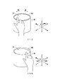
更詳細而言,圖2A與圖2B是依照本發明一實施例的旋鈕輸入裝置的操作示意圖。請參照圖2A,使用者可接觸使用者接觸面S1並沿順時鐘方向D1或逆時鐘方向D2旋轉旋轉機構140。因此,旋轉機構140可以三軸空間裡的上下方向為旋轉軸心而旋轉,而控制器160可依據旋轉機構140沿順時鐘方向D1或逆時鐘方向D2進行旋轉的旋轉量來操控電子裝置200。亦即,控制器160可估計旋轉機構140於立體三軸空間中的偏擺角(yaw)變化量而獲取上述旋轉量。另外,請參照圖2B,使用者可接觸使用者接觸面S1並對使用者接觸面S1上的不同位置施加不同壓力大小,使旋轉機構140以三軸空間裡的左右方向與/或前後方向為旋轉軸心而轉動,從而呈現為傾斜狀態。亦即,於一實施例中,控制器160可估計旋轉機構140於立體三軸空間中的翻滾角(roll)與俯仰角(pitch)而決定旋轉機構140的傾斜方向。In more detail, FIGS. 2A and 2B are schematic diagrams of operations of a knob input device according to an embodiment of the present invention. Referring to FIG. 2A , the user can touch the user contact surface S1 and rotate the rotating mechanism 140 in the clockwise direction D1 or the counterclockwise direction D2 . Therefore, the rotation mechanism 140 can rotate in the up-down direction in the three-axis space as the rotation axis, and the controller 160 can control the electronic device 200 according to the rotation amount of the rotation mechanism 140 in the clockwise direction D1 or the counterclockwise direction D2. That is, the controller 160 can obtain the above-mentioned rotation amount by estimating the yaw angle (yaw) variation of the rotating mechanism 140 in the three-dimensional three-axis space. In addition, referring to FIG. 2B , the user can contact the user contact surface S1 and apply different pressures to different positions on the user contact surface S1 , so that the rotation mechanism 140 is in the left-right direction and/or the front-rear direction in the three-axis space as It rotates by rotating the axis, thus showing a tilted state. That is, in one embodiment, the controller 160 can estimate the roll and pitch angles of the rotating mechanism 140 in the three-dimensional three-axis space to determine the tilting direction of the rotating mechanism 140 .

由此可見,使用者可透過控制旋鈕輸入裝置10中旋轉機構140的旋轉量來輸入使用者指令至電子裝置200,或者,使用者也可透過控制旋鈕輸入裝置10中旋轉機構140的傾斜方向來輸入具有方向性的使用者指令至電子裝置200。舉例而言,使用者可透過操控旋轉機構140的傾斜方向來控制螢幕上的物件(例如游標或鼠標)於螢幕畫面內沿預期方向移動。也就是說,於本發明的實施例中,使用者除了控制旋轉機構140的旋轉量輸入第一類指令至電子裝置200,使用者還可控制旋轉機構140的傾斜方向輸入第二類指令至電子裝置200,從而提昇旋鈕輸入裝置10的功能性。It can be seen that the user can input user commands to the electronic device 200 by controlling the rotation amount of the rotating mechanism 140 in the device 10 via the control knob, or the user can also input the tilt direction of the rotating mechanism 140 in the device 10 by controlling the knob. A directional user command is input to the electronic device 200 . For example, the user can control the object on the screen (such as a cursor or a mouse) to move in a desired direction within the screen by manipulating the tilting direction of the rotating mechanism 140 . That is to say, in the embodiment of the present invention, in addition to controlling the rotation amount of the rotating mechanism 140 to input the first type of commands to the electronic device 200, the user can also control the tilt direction of the rotating mechanism 140 to input the second type of commands to the electronic device 200. device 200 , thereby improving the functionality of the knob input device 10 .

於一實施例中,壓電材料可介於壓力感測電極PE_1~PE_N與公共電極之間,使得壓力感測電極PE_1~PE_N可反應於受力大小而輸出對應的感測訊號。此外,於一實施例中,利用壓電材料輸入電壓會產生變形的材料特性,控制器160可透過對壓力感測電極PE_1~PE_N與公共電極施加特定電壓而使壓電材料產生機械振動,從而提供觸覺回饋給使用者。更詳細而言,在控制器160輸出使用者操作所對應的指令碼給電子裝置200後,電子裝置200可命令控制器160透過施加特定電壓至壓力感測電極PE_1~PE_N與公共電極而產生觸覺回饋。In one embodiment, the piezoelectric material may be interposed between the pressure sensing electrodes PE_1 ˜PE_N and the common electrode, so that the pressure sensing electrodes PE_1 ˜PE_N can output corresponding sensing signals in response to the magnitude of the force. In addition, in one embodiment, using the material property of piezoelectric material that the input voltage will produce deformation, the controller 160 can cause the piezoelectric material to generate mechanical vibration by applying a specific voltage to the pressure sensing electrodes PE_1 ˜PE_N and the common electrode, so as to generate mechanical vibration. Provide haptic feedback to the user. More specifically, after the controller 160 outputs the command code corresponding to the user operation to the electronic device 200, the electronic device 200 can instruct the controller 160 to generate a tactile sensation by applying a specific voltage to the pressure sensing electrodes PE_1-PE_N and the common electrode Give back.

以下將就旋鈕輸入裝置10的各種實施態樣進行說明。Various embodiments of the knob input device 10 will be described below.

[第一實施例][First Embodiment]

圖3A是依照本發明之第一實施例的旋鈕輸入裝置的示意圖。圖3B是依照本發明之第一實施例的基底框架與壓力感測電極的示意圖。請參照圖3A與圖3B,旋鈕輸入裝置20為圖1所示的旋鈕輸入裝置10的一種實施態樣。除了連接裝置150以及控制器160,旋鈕輸入裝置20包括基底框架110_1、承載框架120、多個彈性支撐件130、旋轉機構140。壓力感測電極PE_1~PE_N可配置於基底框架110_1的上表面。具體而言,於一實施例中,共用電極層CL、介電層IL以及感測電極層PL可依序堆疊於基底框架110_1的上表面上。共用電極層CL可包括一或多個共用電極,感測電極層PL可包括壓力感測電極PE_1~PE_N。須說明的是,圖3B僅標示壓力感測電極PE_1,但本領域技術人員可於圖3B輕易理解其他未標示的壓力感測電極。上述共用電極與壓力感測電極PE_1~PE_N電性連接控制器160。當有壓力施加於壓力感測電極PE_1~PE_N時,壓力感測電極PE_1~PE_N與共用電極層CL上的共用電極之間的距離變化會造成電容變化,因而壓力感測電極PE_1~PE_N輸出的感測訊號(例如電壓值)可代表施加於壓力感測電極PE_1~PE_N上的壓力大小。3A is a schematic diagram of a knob input device according to a first embodiment of the present invention. 3B is a schematic diagram of a base frame and a pressure sensing electrode according to the first embodiment of the present invention. Referring to FIGS. 3A and 3B , the knob input device 20 is an implementation of the knob input device 10 shown in FIG. 1 . In addition to the connection device 150 and the controller 160 , the knob input device 20 includes a base frame 110_1 , a carrier frame 120 , a plurality of elastic supports 130 , and a rotation mechanism 140 . The pressure sensing electrodes PE_1 ˜PE_N may be disposed on the upper surface of the base frame 110_1 . Specifically, in one embodiment, the common electrode layer CL, the dielectric layer IL and the sensing electrode layer PL may be sequentially stacked on the upper surface of the base frame 110_1. The common electrode layer CL may include one or more common electrodes, and the sensing electrode layer PL may include pressure sensing electrodes PE_1 ˜PE_N. It should be noted that FIG. 3B only shows the pressure sensing electrode PE_1 , but those skilled in the art can easily understand other unlabeled pressure sensing electrodes in FIG. 3B . The common electrode and the pressure sensing electrodes PE_1 ˜PE_N are electrically connected to the controller 160 . When pressure is applied to the pressure sensing electrodes PE_1 ˜PE_N, the change in the distance between the pressure sensing electrodes PE_1 ˜PE_N and the common electrode on the common electrode layer CL will cause the capacitance to change. The sensing signal (eg, a voltage value) can represent the magnitude of the pressure applied to the pressure sensing electrodes PE_1 ˜PE_N.

承載框架120固定設置於基底框架110_1上方並具有穿孔,且承載框架120的下表面具有環繞穿孔的卡合面S2。於本實施例中,卡合面S2可為傾斜卡合表面,但本發明不限制於此。多個彈性支撐件130設置於承載框架120的上表面。於本實施例中,彈性支撐件130可分別為多個滾珠彈簧。然而,於其他實施例中,彈性支撐件130可為滾珠與其他彈性元件(例如彈性樹脂或彈片結構)的結合。The carrier frame 120 is fixedly disposed above the base frame 110_1 and has a perforation, and a lower surface of the carrier frame 120 has an engaging surface S2 surrounding the perforation. In this embodiment, the engaging surface S2 may be an inclined engaging surface, but the present invention is not limited thereto. A plurality of elastic supports 130 are disposed on the upper surface of the carrying frame 120 . In this embodiment, the elastic support members 130 may be a plurality of ball springs, respectively. However, in other embodiments, the elastic support 130 may be a combination of balls and other elastic elements (eg, elastic resin or elastic sheet structure).

旋轉機構140設置於基底框架110_1上方,且包括蓋件141、支撐桿142、卡合件143、滑動件144,以及多個彈性構件145。蓋件141具有使用者接觸面S1且置放於彈性支撐件130上。於本實施例中,彈性支撐件130分別為多個滾珠彈簧,上述滾珠彈簧的滾珠接觸蓋件141。彈性支撐件130可在使用者旋轉使用者接觸面S1時提供支撐,蓋件141可反應於使用者操作而於彈性支撐件130的滾珠上無阻礙地旋轉。使用者執行的使用者操作施於蓋件141上。支撐桿142的一端連接蓋件141並穿過承載框架120的穿孔。卡合件143設置於支撐桿142的桿體上,且用以與卡合面S2卡合。卡合件143例如為傘齒輪,但本發明不限制於此。當旋轉機構140未被使用者按壓(即彈性支撐件130未被使用者施予的外力擠壓)而位於初始位置,卡合件143卡合於卡合面S2。當旋轉機構140被使用者按壓而下降(即彈性支撐件130被使用者施予的外力擠壓),卡合件143未卡合於卡合面S2,即脫離卡合面S2。The rotation mechanism 140 is disposed above the base frame 110_1 , and includes a cover 141 , a support rod 142 , a locking member 143 , a sliding member 144 , and a plurality of elastic members 145 . The cover 141 has a user contact surface S1 and is placed on the elastic support 130 . In this embodiment, the elastic support members 130 are respectively a plurality of ball springs, and the balls of the ball springs contact the cover member 141 . The elastic support member 130 can provide support when the user rotates the user contact surface S1 , and the cover member 141 can rotate unhindered on the balls of the elastic support member 130 in response to the user's operation. User operations performed by the user are applied to the cover member 141 . One end of the support rod 142 is connected to the cover member 141 and passes through the perforation of the carrying frame 120 . The engaging member 143 is disposed on the rod body of the support rod 142 and is used for engaging with the engaging surface S2. The engaging member 143 is, for example, a bevel gear, but the present invention is not limited thereto. When the rotating mechanism 140 is not pressed by the user (that is, the elastic supporting member 130 is not pressed by the external force exerted by the user) and is located at the initial position, the engaging member 143 is engaged with the engaging surface S2 . When the rotating mechanism 140 is pressed down by the user (ie, the elastic support 130 is pressed by the external force exerted by the user), the engaging element 143 is not engaged with the engaging surface S2 , that is, it is separated from the engaging surface S2 .

滑動件144的上表面連接支撐桿142的另一端,且配置於基底框架110_1與承載框架120之間。多個彈性構件145設置於滑動件144的表面上。於本實施例中,彈性構件145分別為多個滾珠彈簧。然而,於其他實施例中,彈性構件145可為滾珠與其他彈性元件(例如彈性樹脂或彈片結構)的結合。旋轉機構140可回應於使用者操作而往靠近基底框架110_1的方向下降並旋轉或傾斜,使這些彈性構件145向部份的壓力感測電極PE_1~PE_N施加壓力。控制器160依據這些壓力感測電極PE_1~PE_N輸出的感測訊號決定旋轉機構140的旋轉量與傾斜方向,以依據旋轉量與傾斜方向操控電子裝置200。須說明的是,於本實施例中,滑動件144為轉盤,且這些彈性構件145配置於轉盤的側面。如圖3A所示,四個彈性構件145分別位於轉盤的側面。The upper surface of the sliding member 144 is connected to the other end of the support rod 142 and is disposed between the base frame 110_1 and the carrying frame 120 . A plurality of elastic members 145 are provided on the surface of the slider 144 . In this embodiment, the elastic members 145 are respectively a plurality of ball springs. However, in other embodiments, the elastic member 145 may be a combination of balls and other elastic elements (eg, elastic resin or elastic sheet structure). The rotation mechanism 140 can descend and rotate or tilt in the direction close to the base frame 110_1 in response to the user's operation, so that the elastic members 145 apply pressure to some of the pressure sensing electrodes PE_1 ˜PE_N. The controller 160 determines the rotation amount and the tilt direction of the rotating mechanism 140 according to the sensing signals output by the pressure sensing electrodes PE_1 ˜PE_N, so as to control the electronic device 200 according to the rotation amount and the tilt direction. It should be noted that, in this embodiment, the sliding member 144 is a turntable, and the elastic members 145 are arranged on the side surface of the turntable. As shown in FIG. 3A , the four elastic members 145 are respectively located on the sides of the turntable.

如圖3A與圖3B所示,基底框架110_1呈現為圓錐筒狀,多個壓力感測電極PE_1~PE_N可配置於基底框架110_1的內筒面S3上。彈性構件145為滾珠彈簧,彈性構件145的滾珠適於沿內筒面S3滾動。須說明的是,圖3B僅標示壓力感測電極PE_1,但本領域技術人員可於圖3B輕易理解其他未標示的壓力感測電極。於本實施例中,壓力感測電極PE_1~PE_N包括對應至第一層級L1之感測通道CH1~CH12的12個壓力感測電極,像是對應至第一層級L1之感測通道CH2的壓力感測電極PE_1。壓力感測電極PE_1~PE_N還包括對應至第二層級L2之感測通道CH1~CH12的12個壓力感測電極,以及對應至第三層級L3之感測通道CH1~CH12的12個壓力感測電極。對應至第一層級L1的多個壓力感測電極分佈於對應至第二層級L2的多個壓力感測電極的上方,且對應至第二層級L2的多個壓力感測電極分佈於對應至第三層級L3的多個壓力感測電極的上方。As shown in FIGS. 3A and 3B , the base frame 110_1 is in the shape of a conical cylinder, and a plurality of pressure sensing electrodes PE_1 to PE_N can be disposed on the inner cylinder surface S3 of the base frame 110_1 . The elastic member 145 is a ball spring, and the balls of the elastic member 145 are adapted to roll along the inner cylindrical surface S3. It should be noted that FIG. 3B only shows the pressure sensing electrode PE_1 , but those skilled in the art can easily understand other unlabeled pressure sensing electrodes in FIG. 3B . In this embodiment, the pressure sensing electrodes PE_1 ˜PE_N include 12 pressure sensing electrodes corresponding to the sensing channels CH1 ˜ CH12 of the first level L1 , such as the pressure corresponding to the sensing channel CH2 of the first level L1 . Sensing electrode PE_1. The pressure sensing electrodes PE_1-PE_N further include 12 pressure sensing electrodes corresponding to the sensing channels CH1-CH12 of the second level L2, and 12 pressure sensing electrodes corresponding to the sensing channels CH1-CH12 of the third level L3 electrode. The plurality of pressure sensing electrodes corresponding to the first level L1 are distributed above the plurality of pressure sensing electrodes corresponding to the second level L2, and the plurality of pressure sensing electrodes corresponding to the second level L2 are distributed above the plurality of pressure sensing electrodes corresponding to the second level L2. Above the multiple pressure sensing electrodes of the third level L3.

於本實施例中,當旋轉機構140未被按壓,彈性構件145不會接觸到任何壓力感測電極。當旋轉機構140被按壓而下降,彈性構件145將對部分的壓力感測電極施加壓力。於本實施例中,彈性構件145分別為滾珠彈簧,上述滾珠彈簧的滾珠接觸部份的壓力感測電極而對其施加壓力。In this embodiment, when the rotating mechanism 140 is not pressed, the elastic member 145 will not contact any pressure sensing electrodes. When the rotating mechanism 140 is pressed to descend, the elastic member 145 will exert pressure on part of the pressure sensing electrodes. In this embodiment, the elastic members 145 are respectively ball springs, and the balls of the ball springs contact the pressure sensing electrodes of the portion to apply pressure to them.

圖4A至圖4F是依照本發明之第一實施例的旋鈕輸入裝置接收使用者操作的示意圖。須說明的是,圖4A至圖4F所示之感測訊號的準位僅為示範性說明。4A to 4F are schematic diagrams of the knob input device receiving user operations according to the first embodiment of the present invention. It should be noted that the levels of the sensing signals shown in FIG. 4A to FIG. 4F are only exemplary.

請合併參照圖3A、圖3B與圖4A,當未有使用者操作施於旋鈕輸入裝置20時,旋轉機構140未被按壓而位於初始位置,卡合件143卡合於承載框架120上。當卡合件143卡合於承載框架120上時,使用者無法改變旋轉機構140於三軸空間中的運動姿態。此時,基於彈性支撐件130的支撐,彈性構件145不會接觸到任何壓力感測電極。因此,所有壓力感測電極的感測訊號皆為準位0。對應的,旋鈕輸入裝置20不產生使用者指令給電子裝置200。Please refer to FIGS. 3A , 3B and 4A together. When no user operates the knob input device 20 , the rotating mechanism 140 is not pressed and is located at the initial position, and the engaging member 143 is engaged with the carrying frame 120 . When the engaging member 143 is engaged with the carrying frame 120, the user cannot change the movement posture of the rotating mechanism 140 in the three-axis space. At this time, based on the support of the elastic supporter 130, the elastic member 145 will not contact any pressure sensing electrodes. Therefore, the sensing signals of all the pressure sensing electrodes are at the level of 0. Correspondingly, the knob input device 20 does not generate user commands to the electronic device 200 .

請合併參照圖3A、圖3B與圖4B,當有使用者操作施於旋鈕輸入裝置20且手F1平均地對使用者接觸面S1施力下壓時,旋轉機構140被按壓而下降,卡合件143脫離承載框架120。當卡合件143卡合脫離承載框架120時,使用者才可改變旋轉機構140於三軸空間中的運動姿態。此時,由於手F1平均地對使用者接觸面S1施力下壓,彈性構件145朝對應於第一層級L1之感測通道CH2、CH5、CH8、CH11的四個壓力感測電極平均地施壓。因此,如圖所示,第一層級L1之感測通道CH2、CH5、CH8、CH11的感測訊號皆為準位0.2。控制器160因而可判斷旋轉機構140沒有傾斜,而不會輸出有關於傾斜方向的使用者指令給電子裝置200。可推知地,當手F1平均地對使用者接觸面S1更大力下壓時,滑動件144可繼續下降,彈性構件145朝對應於第二層級L2或第三層級L3之感測通道CH2、CH5、CH8、CH11的四個壓力感測電極平均地施壓。Please refer to FIG. 3A , FIG. 3B and FIG. 4B together, when a user operates the knob input device 20 and the hand F1 evenly presses the user contact surface S1 , the rotating mechanism 140 is pressed to descend and engage The member 143 is disengaged from the carrier frame 120 . When the engaging member 143 is engaged and disengaged from the carrying frame 120 , the user can change the movement posture of the rotating mechanism 140 in the three-axis space. At this time, since the hand F1 pushes down the user contact surface S1 evenly, the elastic member 145 pushes evenly toward the four pressure sensing electrodes corresponding to the sensing channels CH2, CH5, CH8, CH11 of the first level L1 pressure. Therefore, as shown in the figure, the sensing signals of the sensing channels CH2 , CH5 , CH8 , and CH11 of the first level L1 are all at level 0.2. Therefore, the controller 160 can determine that the rotating mechanism 140 is not tilted, and will not output a user command related to the tilting direction to the electronic device 200 . It can be deduced that when the hand F1 presses the user contact surface S1 with greater force on average, the sliding member 144 can continue to descend, and the elastic member 145 will move toward the sensing channels CH2 and CH5 corresponding to the second level L2 or the third level L3. The four pressure sensing electrodes of , CH8 and CH11 apply pressure evenly.

請合併參照圖3A、圖3B與圖4C,當有使用者操作施於旋鈕輸入裝置20且手F1非平均地對使用者接觸面S1下壓時,旋轉機構140回應於使用者操作而下降並傾斜。當旋轉機構140回應於使用者操作而下降並傾斜,彈性構件145向對應於第一層級L1的部分壓力感測電極以及對應於第二層級L2的壓力感測電極其中之一施加壓力,使控制器160依據對應於第二層級L2的壓力感測電極其中之一的分佈位置決定旋轉機構140的傾斜方向。於此,三個彈性構件145向對應於第一層級L1之感測通道CH5、CH8、CH11的三個壓力感測電極施加壓力,其餘一個彈性構件145向對應於第二層級L2之感測通道CH2的ㄧ個壓力感測電極施加壓力。基於彈性構件145之壓縮程度不同,第一層級L1之感測通道CH5、CH8、CH11的感測訊號的訊號準位以及第二層級L2之感測通道CH2的感測訊號的訊號準位會有所差異。因此,如圖所示,第一層級L1之感測通道CH5、CH8、CH11的感測訊號分別約為準位0.2、0.1、0.2,而第二層級L2之感測通道CH2的感測訊號約為準位0.4。基於感測通道CH8的感測訊號的訊號準位為最小值且感測通道CH2的感測訊號的訊號準位為最大值,控制器160因而可判斷旋轉機構140往感測通道CH2對應的方位傾倒,而輸出有關於傾斜方向的使用者指令給電子裝置200。Please refer to FIG. 3A , FIG. 3B and FIG. 4C together. When a user operates the knob input device 20 and the hand F1 presses the user contact surface S1 unevenly, the rotating mechanism 140 descends in response to the user operation and tilt. When the rotating mechanism 140 descends and tilts in response to the user's operation, the elastic member 145 applies pressure to one of the part of the pressure sensing electrodes corresponding to the first level L1 and the pressure sensing electrodes corresponding to the second level L2, so that the control The controller 160 determines the tilting direction of the rotating mechanism 140 according to the distribution position of one of the pressure sensing electrodes corresponding to the second level L2. Here, the three elastic members 145 apply pressure to the three pressure sensing electrodes corresponding to the sensing channels CH5, CH8, CH11 of the first level L1, and the remaining one elastic member 145 applies pressure to the sensing channels corresponding to the second level L2 One pressure sensing electrode of CH2 applies pressure. Based on the different compression degrees of the elastic member 145, the signal levels of the sensing signals of the sensing channels CH5, CH8 and CH11 of the first level L1 and the signal levels of the sensing signals of the sensing channel CH2 of the second level L2 will have the difference. Therefore, as shown in the figure, the sensing signals of the sensing channels CH5, CH8, and CH11 of the first level L1 are about 0.2, 0.1, and 0.2, respectively, while the sensing signals of the sensing channel CH2 of the second level L2 are about 0.2, 0.1, and 0.2. The standard is 0.4. Based on the signal level of the sensing signal of the sensing channel CH8 being the minimum value and the signal level of the sensing signal of the sensing channel CH2 being the maximum value, the controller 160 can thus determine the orientation of the rotating mechanism 140 corresponding to the sensing channel CH2 Tilting, and outputting a user command about the tilting direction to the electronic device 200 .

請合併參照圖3A、圖3B與圖4D,當有使用者操作施於旋鈕輸入裝置20且手F1非平均地對使用者接觸面S1下壓時,旋轉機構140回應於使用者操作而下降並傾斜。相似於圖4C的操作原理,彈性構件145向對應於第一層級L1的部分壓力感測電極以及對應於第二層級L2的壓力感測電極其中之一施加壓力,使控制器160依據對應於第二層級L2的壓力感測電極其中之一的分佈位置決定旋轉機構140的傾斜方向。如圖所示,第一層級L1之感測通道CH2、CH5、CH11的感測訊號分別約為準位0.1、0.2、0.2,而第二層級L2之感測通道CH8的感測訊號約為準位0.4。基於感測通道CH2的感測訊號的訊號準位為最小值且感測通道CH8的感測訊號的訊號準位為最大值,控制器160因而可判斷旋轉機構140往感測通道CH8對應的方位傾倒,而輸出有關於傾斜方向的使用者指令給電子裝置200。Please refer to FIG. 3A , FIG. 3B and FIG. 4D together, when a user operates the knob input device 20 and the hand F1 presses the user contact surface S1 unevenly, the rotating mechanism 140 descends in response to the user operation and tilt. Similar to the operation principle of FIG. 4C , the elastic member 145 applies pressure to one of the part of the pressure sensing electrodes corresponding to the first level L1 and the pressure sensing electrodes corresponding to the second level L2, so that the controller 160 can make the The distribution position of one of the pressure sensing electrodes of the second level L2 determines the tilting direction of the rotating mechanism 140 . As shown in the figure, the sensing signals of the sensing channels CH2, CH5, and CH11 of the first level L1 are about 0.1, 0.2, and 0.2, respectively, while the sensing signals of the sensing channel CH8 of the second level L2 are about the same. Bit 0.4. Based on the signal level of the sensing signal of the sensing channel CH2 being the minimum value and the signal level of the sensing signal of the sensing channel CH8 being the maximum value, the controller 160 can thus determine the corresponding orientation of the rotating mechanism 140 to the sensing channel CH8 Tilting, and outputting a user command about the tilting direction to the electronic device 200 .

請合併參照圖3A、圖3B與圖4E,當有使用者操作施於旋鈕輸入裝置20且手F1非平均地對使用者接觸面S1下壓時,旋轉機構140回應於使用者操作而下降並傾斜。相似於圖4C與圖4D的操作原理,第一層級L1之感測通道CH2、CH5、CH8的感測訊號分別約為準位0.2、0.1、0.2,而第二層級L2之感測通道CH11的感測訊號約為準位0.4。基於感測通道CH5的感測訊號的訊號準位為最小值且感測通道CH11的感測訊號的訊號準位為最大值,控制器160因而可判斷旋轉機構140往感測通道CH11對應的方位傾倒,而輸出有關於傾斜方向的使用者指令給電子裝置200。Please refer to FIG. 3A , FIG. 3B and FIG. 4E together. When a user operates the knob input device 20 and the hand F1 presses the user contact surface S1 unevenly, the rotating mechanism 140 descends in response to the user operation and tilt. Similar to the operation principle of FIG. 4C and FIG. 4D , the sensing signals of the sensing channels CH2 , CH5 and CH8 of the first level L1 are about 0.2, 0.1 and 0.2 respectively, while the sensing signals of the sensing channel CH11 of the second level L2 are about 0.2, 0.1 and 0.2 respectively. The sensing signal is about 0.4 of the standard. Based on the signal level of the sensing signal of the sensing channel CH5 being the minimum value and the signal level of the sensing signal of the sensing channel CH11 being the maximum value, the controller 160 can thus determine the orientation of the rotating mechanism 140 corresponding to the sensing channel CH11 Tilting, and outputting a user command about the tilting direction to the electronic device 200 .

請合併參照圖3A、圖3B與圖4F,當有使用者操作施於旋鈕輸入裝置20且手F1按壓且旋轉對使用者接觸面S1時,旋轉機構140回應於使用者操作而下降並旋轉。於旋轉機構140回應於使用者操作而旋轉的期間,彈性構件145於不同時間點依據先後順序向部份的壓力感測電極施加壓力,使控制器160可據以決定旋轉機構140的旋轉量。如圖所示,於使用者按壓旋轉機構140至釋放旋轉機構140的期間,若感測通道CH2、CH3、CH4分別於連續時間點t1、t2、t3分別輸出為高準位的感測訊號V1、V2、V3,控制器160可判斷旋轉機構140的旋轉量為90度。因此,控制器160可輸出有關於旋轉量的使用者指令給電子裝置200。3A, 3B and 4F, when a user operates the knob input device 20 and the hand F1 presses and rotates against the user contact surface S1, the rotating mechanism 140 descends and rotates in response to the user's operation. During the period when the rotating mechanism 140 rotates in response to the user's operation, the elastic member 145 applies pressure to some of the pressure sensing electrodes in sequence at different time points, so that the controller 160 can determine the rotation amount of the rotating mechanism 140 accordingly. As shown in the figure, when the user presses the rotating mechanism 140 to release the rotating mechanism 140 , if the sensing channels CH2 , CH3 , and CH4 respectively output a high-level sensing signal V1 at successive time points t1 , t2 , and t3 , V2, V3, the controller 160 can determine that the rotation amount of the rotating mechanism 140 is 90 degrees. Therefore, the controller 160 can output a user command regarding the rotation amount to the electronic device 200 .

[第二實施例][Second Embodiment]

圖5A是依照本發明之第二實施例的旋鈕輸入裝置的示意圖。圖5B是依照本發明之第二實施例的基底框架與壓力感測電極的示意圖。請參照圖5A與圖5B,旋鈕輸入裝置30為圖1所示的旋鈕輸入裝置10的一種實施態樣。除了連接裝置150以及控制器160,旋鈕輸入裝置30包括基底框架110_2、承載框架120、多個彈性支撐件130、旋轉機構140。壓力感測電極PE_1~PE_N可配置於基底框架110_2的上表面。具體而言,於一實施例中,共用電極層CL、介電層IL以及感測電極層PL可依序堆疊於基底框架110_2的上表面上。共用電極層CL可包括一或多個共用電極,感測電極層PL可包括分別對應至感測通道CH1~CH16的壓力感測電極PE_1~PE_N。須說明的是,圖5B僅標示壓力感測電極PE_1,但本領域技術人員可於圖5B輕易理解其他未標示的壓力感測電極。上述共用電極與壓力感測電極PE_1~PE_N電性連接控制器160。壓力感測電極PE_1~PE_N感測壓力大小的原理相似於第一實施例的說明。此外,使用者同樣可控制旋轉機構140的旋轉量與傾斜方向,從而提供對應的使用者指令至電子裝置200而操控子裝置200。5A is a schematic diagram of a knob input device according to a second embodiment of the present invention. 5B is a schematic diagram of a base frame and a pressure sensing electrode according to the second embodiment of the present invention. Please refer to FIG. 5A and FIG. 5B , the knob input device 30 is an implementation of the knob input device 10 shown in FIG. 1 . In addition to the connection device 150 and the controller 160 , the knob input device 30 includes a base frame 110_2 , a carrier frame 120 , a plurality of elastic support members 130 , and a rotation mechanism 140 . The pressure sensing electrodes PE_1 ˜PE_N may be disposed on the upper surface of the base frame 110_2 . Specifically, in one embodiment, the common electrode layer CL, the dielectric layer IL, and the sensing electrode layer PL may be sequentially stacked on the upper surface of the base frame 110_2. The common electrode layer CL may include one or more common electrodes, and the sensing electrode layer PL may include pressure sensing electrodes PE_1 ˜PE_N corresponding to the sensing channels CH1 ˜ CH16 , respectively. It should be noted that FIG. 5B only shows the pressure sensing electrode PE_1 , but those skilled in the art can easily understand other unlabeled pressure sensing electrodes in FIG. 5B . The common electrode and the pressure sensing electrodes PE_1 ˜PE_N are electrically connected to the controller 160 . The principle of the pressure sensing electrodes PE_1 ˜PE_N for sensing the magnitude of the pressure is similar to that described in the first embodiment. In addition, the user can also control the rotation amount and the tilting direction of the rotating mechanism 140 , so as to provide corresponding user commands to the electronic device 200 to control the sub-device 200 .

須說明的是,與第一實施例不同的是,於本實施例中,這些彈性構件145包括提供支撐功能的彈性構件145a以及用以偵測旋轉機構140之旋轉量與傾斜方向的彈性構件145b。滑動件144為轉盤,且彈性構件145a、145b是配置於轉盤的下表面。如5A所示,彈性構件145a配置於轉盤下表面的圓心處與靠近表面邊緣處。彈性構件145b分別位於轉盤下表面的特定位置。然而,圖示的彈性構件145a、145b的配置分佈僅為一種示範說明,並非用以限定本發明。It should be noted that, different from the first embodiment, in this embodiment, the elastic members 145 include elastic members 145 a for providing a support function and elastic members 145 b for detecting the rotation amount and the tilting direction of the rotating mechanism 140 . . The slider 144 is a turntable, and the elastic members 145a and 145b are arranged on the lower surface of the turntable. As shown in 5A, the elastic member 145a is disposed at the center of the lower surface of the turntable and near the edge of the surface. The elastic members 145b are located at specific positions on the lower surface of the turntable, respectively. However, the illustrated arrangement and distribution of the elastic members 145a and 145b is only an exemplary illustration, and is not intended to limit the present invention.

此外,如圖5A與圖5B所示,基底框架110_2呈現為圓盤狀,多個壓力感測電極PE_1~PE_N可配置於基底框架110_2的盤底面S4上。須說明的是,圖5B僅標示壓力感測電極PE_1,但本領域技術人員可於圖5B輕易理解其他未標示的壓力感測電極。於本實施例中,壓力感測電極PE_1~PE_N位於同一平面上且包括對應至感測通道CH9~CH16的多個壓力感測電極以及對應至感測通道CH1~CH8的多個壓力感測電極。其中,對應至感測通道CH9~CH16的多個壓力感測電極於盤底面S4上分佈排列為內圈,對應至感測通道CH1~CH8的多個壓力感測電極於盤底面S4上分佈排列為外圈。像是,對應至感測通道CH1的壓力感測電極PE_1位於外圈。In addition, as shown in FIG. 5A and FIG. 5B , the base frame 110_2 is in the shape of a disc, and a plurality of pressure sensing electrodes PE_1 to PE_N can be disposed on the bottom surface S4 of the base frame 110_2 . It should be noted that FIG. 5B only shows the pressure sensing electrode PE_1 , but those skilled in the art can easily understand other unlabeled pressure sensing electrodes in FIG. 5B . In this embodiment, the pressure sensing electrodes PE_1 ˜PE_N are located on the same plane and include a plurality of pressure sensing electrodes corresponding to the sensing channels CH9 ˜ CH16 and a plurality of pressure sensing electrodes corresponding to the sensing channels CH1 ˜ CH8 . The pressure sensing electrodes corresponding to the sensing channels CH9-CH16 are distributed and arranged as an inner circle on the bottom surface S4 of the disk, and the pressure sensing electrodes corresponding to the sensing channels CH1-CH8 are distributed and arranged on the bottom surface S4 of the disk for the outer ring. For example, the pressure sensing electrode PE_1 corresponding to the sensing channel CH1 is located on the outer circle.

於本實施例中,當旋轉機構140未被按壓,彈性構件145b不會接觸到任何壓力感測電極。當旋轉機構140被按壓而下降,彈性構件145b將對部分壓力感測電極施加壓力。於本實施例中,彈性構件145a、145b同樣分別為滾珠彈簧,彈性構件145a、145b的滾珠適於沿盤底面S4滾動。相似於第一實施例,控制器160可依據對應至感測通道CH1~CH16的多壓力感測電極PE_1~PE_N輸出的感測訊號來判斷旋轉機構140的傾斜方向與旋轉量。In this embodiment, when the rotating mechanism 140 is not pressed, the elastic member 145b will not contact any pressure sensing electrodes. When the rotating mechanism 140 is pressed to descend, the elastic member 145b will apply pressure to part of the pressure sensing electrodes. In this embodiment, the elastic members 145a and 145b are also ball springs respectively, and the balls of the elastic members 145a and 145b are suitable for rolling along the bottom surface S4 of the disk. Similar to the first embodiment, the controller 160 can determine the tilt direction and the rotation amount of the rotating mechanism 140 according to the sensing signals output by the multiple pressure sensing electrodes PE_1 ˜PE_N corresponding to the sensing channels CH1 ˜ CH16 .

圖6A至圖6C是依照本發明之第二實施例的判定旋轉量與傾斜方向的示意圖。6A to 6C are schematic diagrams of determining the rotation amount and the tilt direction according to the second embodiment of the present invention.

請合併參照圖5A、圖5B與圖6A,當有使用者操作施於旋鈕輸入裝置30且手平均地對使用者接觸面S1下壓時,旋轉機構140被按壓而下降,卡合件143脫離承載框架120。當卡合件143卡合脫離承載框架120時,使用者才可改變旋轉機構140於三軸空間中的運動姿態。由於手平均地對使用者接觸面S1下壓,彈性構件145b朝對應於感測通道CH1、CH3、CH7、CH13、CH15的壓力感測電極平均地施壓。因此,如圖所示,感測通道CH1、CH3、CH7、CH13、CH15的感測訊號皆約為準位0.5。控制器160因而可判斷旋轉機構140沒有傾斜,而不會輸出有關於傾斜方向的使用者指令給電子裝置200。接著,當使用者控制旋轉機構140旋轉45度,基於手平均地對使用者接觸面S1下壓,彈性構件145b改變為朝對應於感測通道CH2、CH4、CH8、CH14、CH16的壓力感測電極平均地施壓。因此,如圖所示,感測通道CH2、CH4、CH8、CH14、CH16的感測訊號皆約為準位0.5,而控制器160可依據連續時間點上感測通道CH1、CH3、CH7、CH13、CH15輸出的訊號準位以及感測通道CH2、CH4、CH8、CH14、CH16的輸出的訊號準位而獲取旋轉量為45度。依此類推,請合併參照圖5A、圖5B與圖6B,當使用者控制旋轉機構140旋轉90度或135度,控制器160可依據連續時間點上感測通道CH1~CH16所輸出之感測訊號的訊號準位決定旋轉機構140的旋轉量。Please refer to FIG. 5A , FIG. 5B and FIG. 6A together. When a user operates the knob input device 30 and the hand presses the user contact surface S1 evenly, the rotating mechanism 140 is pressed and lowered, and the engaging member 143 is disengaged The carrier frame 120 is carried. When the engaging member 143 is engaged and disengaged from the carrying frame 120 , the user can change the movement posture of the rotating mechanism 140 in the three-axis space. Since the hand presses down on the user contact surface S1 evenly, the elastic member 145b presses evenly toward the pressure sensing electrodes corresponding to the sensing channels CH1 , CH3 , CH7 , CH13 , CH15 . Therefore, as shown in the figure, the sensing signals of the sensing channels CH1 , CH3 , CH7 , CH13 , and CH15 are all about the level of 0.5. Therefore, the controller 160 can determine that the rotating mechanism 140 is not tilted, and will not output a user command related to the tilting direction to the electronic device 200 . Next, when the user controls the rotation mechanism 140 to rotate by 45 degrees, based on the average pressure of the hand on the user contact surface S1, the elastic member 145b changes to sense the pressure corresponding to the sensing channels CH2, CH4, CH8, CH14, CH16 The electrodes are pressed evenly. Therefore, as shown in the figure, the sensing signals of the sensing channels CH2, CH4, CH8, CH14, and CH16 are all about 0.5, and the controller 160 can sense the channels CH1, CH3, CH7, and CH13 according to consecutive time points. , the output signal level of CH15 and the output signal level of sensing channels CH2, CH4, CH8, CH14 and CH16 to obtain the rotation amount of 45 degrees. By analogy, please refer to FIG. 5A , FIG. 5B and FIG. 6B together, when the user controls the rotation mechanism 140 to rotate 90 degrees or 135 degrees, the controller 160 can be based on the sensing output from the sensing channels CH1 - CH16 at successive time points The signal level of the signal determines the rotation amount of the rotating mechanism 140 .

須說明的是,相似於第一實施例偵測傾斜方向的原理,於本實施例中,當旋轉機構140回應於使用者操作而下降並傾斜,彈性構件145b其中之兩者向壓力感測電極PE_1~PE_N其中之兩者施加不同壓力,使控制器160依據壓力感測電極PE_1~PE_N其中之兩者的分佈位置決定旋轉機構的傾斜方向。如圖6C所示,當有使用者操作施於旋鈕輸入裝置30且手非平均地對使用者接觸面S1下壓時,旋轉機構140回應於使用者操作而下降並傾斜。當旋轉機構140回應於使用者操作而下降並傾斜,彈性構件145b對感測通道CH2、CH4、CH10的壓力感測電極施加較大的壓力,並對對感測通道CH6、CH16的壓力感測電極施加較小的壓力。如圖所示,感測通道CH2、CH4、CH10的感測訊號皆約為準位0.8,而感測通道CH6、CH16的感測訊號皆約為準位0.5。基此,控制器160可依據感測通道CH2、CH6、CH4、CH10、CH16的感測訊號判斷旋轉機構140向一特定方位(例如使用者右方)傾倒,從而輸出有關於傾斜方向的輸出指令給電子裝置200。It should be noted that, similar to the principle of detecting the tilting direction in the first embodiment, in this embodiment, when the rotating mechanism 140 descends and tilts in response to the user's operation, two of the elastic members 145b are directed toward the pressure sensing electrodes. Two of PE_1 ˜PE_N apply different pressures, so that the controller 160 determines the tilting direction of the rotating mechanism according to the distribution positions of the two pressure sensing electrodes PE_1 ˜PE_N. As shown in FIG. 6C , when a user operates the knob input device 30 and the hand presses the user contact surface S1 unevenly, the rotating mechanism 140 descends and tilts in response to the user's operation. When the rotating mechanism 140 descends and tilts in response to the user's operation, the elastic member 145b exerts greater pressure on the pressure sensing electrodes of the sensing channels CH2, CH4, CH10, and senses the pressure on the sensing channels CH6, CH16 The electrodes apply less pressure. As shown in the figure, the sensing signals of the sensing channels CH2, CH4, and CH10 are all about the level of 0.8, and the sensing signals of the sensing channels CH6 and CH16 are all about the level of 0.5. Based on this, the controller 160 can determine that the rotating mechanism 140 is tilted to a specific direction (eg, the user's right) according to the sensing signals of the sensing channels CH2 , CH6 , CH4 , CH10 , and CH16 , so as to output an output command related to the tilting direction. to the electronic device 200 .

[第三實施例][Third Embodiment]

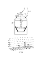
圖7A是依照本發明之第二實施例的旋鈕輸入裝置的示意圖。圖7B是依照本發明之第二實施例的基底框架與壓力感測電極的示意圖。請參照圖7A與圖7B,旋鈕輸入裝置40為圖1所示的旋鈕輸入裝置10的一種實施態樣。除了連接裝置150以及控制器160,旋鈕輸入裝置40包括基底框架110_3、承載框架120、多個彈性支撐件130、旋轉機構140。壓力感測電極PE_1~PE_N可配置於基底框架110_3的上表面。具體而言,於一實施例中,共用電極層CL、介電層IL以及感測電極層PL可依序堆疊於基底框架110_3的上表面上。共用電極層CL可包括一或多個共用電極,感測電極層PL可包括分別對應至感測通道CH1~CH8的壓力感測電極PE_1~PE_N。須說明的是,圖7B僅標示壓力感測電極PE_1,但本領域技術人員可於圖7B輕易理解其他未標示的壓力感測電極。上述共用電極與壓力感測電極PE_1~PE_N電性連接控制器160。壓力感測電極PE_1~PE_N感測壓力大小的原理相似於第一實施例的說明。此外,使用者同樣可控制旋轉機構140的旋轉量與傾斜方向,從而提供對應的使用者指令至電子裝置200而操控子裝置200。7A is a schematic diagram of a knob input device according to a second embodiment of the present invention. 7B is a schematic diagram of a base frame and a pressure sensing electrode according to a second embodiment of the present invention. Referring to FIGS. 7A and 7B , the knob input device 40 is an implementation of the knob input device 10 shown in FIG. 1 . In addition to the connection device 150 and the controller 160 , the knob input device 40 includes a base frame 110_3 , a carrier frame 120 , a plurality of elastic support members 130 , and a rotation mechanism 140 . The pressure sensing electrodes PE_1 ˜PE_N may be disposed on the upper surface of the base frame 110_3 . Specifically, in one embodiment, the common electrode layer CL, the dielectric layer IL, and the sensing electrode layer PL may be sequentially stacked on the upper surface of the base frame 110_3. The common electrode layer CL may include one or more common electrodes, and the sensing electrode layer PL may include pressure sensing electrodes PE_1 ˜PE_N corresponding to the sensing channels CH1 ˜ CH8 , respectively. It should be noted that FIG. 7B only indicates the pressure sensing electrode PE_1 , but those skilled in the art can easily understand other unlabeled pressure sensing electrodes in FIG. 7B . The common electrode and the pressure sensing electrodes PE_1 ˜PE_N are electrically connected to the controller 160 . The principle of the pressure sensing electrodes PE_1 ˜PE_N for sensing the magnitude of the pressure is similar to that described in the first embodiment. In addition, the user can also control the rotation amount and the tilting direction of the rotating mechanism 140 , so as to provide corresponding user commands to the electronic device 200 to control the sub-device 200 .

須說明的是,相似於第二實施例,於本實施例中,這些彈性構件145包括提供支撐功能的彈性構件145a以及用以偵測旋轉機構140之旋轉量與傾斜方向的彈性構件145b。相異於第一實施例與第二實施例,於本實施例中,基底框架110_3呈現為一圓碗狀,壓力感測電極感測電極PE_1~PE_N配置於基底框架110_3的碗底面S5上。對應的,滑動件144為一半球體,滑動件144的上表面為平面且連接支撐桿142,彈性構件145配置於半球體的球面上。然而,圖示的彈性構件145a、145b的配置僅為一種示範說明,並非用以限定本發明。彈性構件145a、145b為滾珠彈簧,彈性構件145a、145b的滾珠適於沿碗底面S5滾動。It should be noted that, similar to the second embodiment, in this embodiment, the elastic members 145 include an elastic member 145a for providing a support function and an elastic member 145b for detecting the rotation amount and the inclination direction of the rotating mechanism 140 . Different from the first embodiment and the second embodiment, in this embodiment, the base frame 110_3 is in the shape of a circular bowl, and the pressure sensing electrodes PE_1 ˜PE_N are disposed on the bowl bottom surface S5 of the base frame 110_3 . Correspondingly, the sliding member 144 is a hemisphere, the upper surface of the sliding member 144 is a plane and is connected to the support rod 142 , and the elastic member 145 is disposed on the spherical surface of the hemisphere. However, the illustrated configuration of the elastic members 145a and 145b is only an exemplary illustration, and is not intended to limit the present invention. The elastic members 145a, 145b are ball springs, and the balls of the elastic members 145a, 145b are adapted to roll along the bowl bottom surface S5.

圖8是依照本發明之第三實施例的旋鈕輸入裝置接收使用者操作的示意圖。請同時參照圖7A、圖7B與圖8,當有使用者操作施於旋鈕輸入裝置40且手F2平均地對使用者接觸面S1下壓時,旋轉機構140被按壓而下降,卡合件143脫離承載框架120。當卡合件143卡合脫離承載框架120時,使用者才可改變旋轉機構140於三軸空間中的運動姿態。由於手平均地對使用者接觸面S1下壓,彈性構件145b朝對應於感測通道CH1~CH8其中四者的四個壓力感測電極平均地施壓。接著,當使用者的手F2非平均地對使用者接觸面S1下壓時,旋轉機構140回應於使用者操作而下降並傾斜。當旋轉機構140回應於使用者操作而下降並傾斜,彈性構件145b其中之兩者的壓縮程度不同,因此彈性構件145b其中之兩者向壓力感測電極其中之兩者施加不同壓力,使控制器160依據壓力感測電極其中之兩者的分佈位置決定旋轉機構140的傾斜方向。8 is a schematic diagram of a knob input device according to a third embodiment of the present invention receiving user operations. Please refer to FIGS. 7A , 7B and 8 at the same time, when a user operates the knob input device 40 and the hand F2 presses the user contact surface S1 evenly, the rotating mechanism 140 is pressed and lowered, and the engaging member 143 Detach the carrier frame 120 . When the engaging member 143 is engaged and disengaged from the carrying frame 120 , the user can change the movement posture of the rotating mechanism 140 in the three-axis space. Since the hand presses down on the user contact surface S1 evenly, the elastic member 145b presses evenly toward the four pressure sensing electrodes corresponding to four of the sensing channels CH1 ˜ CH8 . Next, when the user's hand F2 presses the user contact surface S1 unevenly, the rotating mechanism 140 descends and tilts in response to the user's operation. When the rotating mechanism 140 descends and tilts in response to the user's operation, two of the elastic members 145b have different degrees of compression, so the two of the elastic members 145b apply different pressures to two of the pressure sensing electrodes, so that the controller 160 determines the inclination direction of the rotating mechanism 140 according to the distribution positions of the two pressure sensing electrodes.

綜上所述,於本發明實施例中,當使用者操作施於旋鈕輸入裝置的旋轉機構上時,旋鈕輸入裝置的控制器可基於壓力感測電極所輸出的感測訊號而得知旋轉機構的傾斜方向或旋轉量。藉此,使用者可透過控制旋轉機構的旋轉量與傾斜方向來輸入使用者指令以操控電子裝置。本發明的旋鈕輸入裝置還可作為指向性輸入裝置,使用者可透過更多樣化的操作方是來操作旋鈕輸入裝置。如此一來,本發明不僅可擴展旋鈕輸入裝置的應用範圍,更可提昇旋鈕輸入裝置的操作便利性。To sum up, in the embodiment of the present invention, when the user operates the rotating mechanism of the knob input device, the controller of the knob input device can know the rotation mechanism based on the sensing signal output by the pressure sensing electrode direction of tilt or amount of rotation. In this way, the user can control the electronic device by inputting user commands by controlling the rotation amount and the tilting direction of the rotating mechanism. The knob input device of the present invention can also be used as a directional input device, and the user can operate the knob input device through more diversified operation methods. In this way, the present invention can not only expand the application range of the knob input device, but also improve the operational convenience of the knob input device.

雖然本發明已以實施例揭露如上,然其並非用以限定本發明,任何所屬技術領域中具有通常知識者,在不脫離本發明的精神和範圍內,當可作些許的更動與潤飾,故本發明的保護範圍當視後附的申請專利範圍所界定者為準。Although the present invention has been disclosed above by the embodiments, it is not intended to limit the present invention. Anyone with ordinary knowledge in the technical field can make some changes and modifications without departing from the spirit and scope of the present invention. Therefore, The protection scope of the present invention shall be determined by the scope of the appended patent application.

10、20、30、40:旋鈕輸入裝置 S1:使用者接觸面 110_1、110_2、110_3:底座框架 120:支撐框架 130:彈性支撐件 140:旋轉機構 141:蓋件 142:支撐桿 143:卡合件 144:滑動件 145、145a、145b:彈性構件 PL:感測電極層 IL:介電層 CL:共用電極層 150:連接裝置 160:控制器 200:電子裝置 PE_1~PE_N:壓力感測電極 D1:順時鐘方向 D2:逆時鐘方向 S3:內筒面 S4:盤底面 S5:碗底面 F1、F2:手 V1~V3:感測訊號 10, 20, 30, 40: Knob input device S1: User interface 110_1, 110_2, 110_3: base frame 120: Support frame 130: elastic support 140: Rotary Mechanism 141: Cover 142: Support rod 143: Snaps 144: Slider 145, 145a, 145b: elastic members PL: Sensing electrode layer IL: Dielectric Layer CL: Common electrode layer 150: Connection device 160: Controller 200: Electronics PE_1~PE_N: Pressure sensing electrodes D1: Clockwise direction D2: Counterclockwise direction S3: inner cylinder surface S4: Disc Bottom S5: Bowl Bottom F1, F2: hand V1~V3: Sensing signal

圖1是依照本發明一實施例的旋鈕輸入裝置的示意圖。 圖2A與圖2B是依照本發明一實施例的旋鈕輸入裝置的操作示意圖。 圖3A是依照本發明之第一實施例的旋鈕輸入裝置的示意圖。 圖3B是依照本發明之第一實施例的基底框架與壓力感測電極的示意圖。 圖4A至圖4F是依照本發明之第一實施例的旋鈕輸入裝置接收使用者操作的示意圖。 圖5A是依照本發明之第二實施例的旋鈕輸入裝置的示意圖。 圖5B是依照本發明之第二實施例的基底框架與壓力感測電極的示意圖。 圖6A至圖6C是依照本發明之第二實施例的判定旋轉量與傾斜方向的示意圖。 圖7A是依照本發明之第三實施例的旋鈕輸入裝置的示意圖。 圖7B是依照本發明之第三實施例的基底框架與壓力感測電極的示意圖。 圖8是依照本發明之第三實施例的旋鈕輸入裝置接收使用者操作的示意圖。 FIG. 1 is a schematic diagram of a knob input device according to an embodiment of the present invention. 2A and 2B are schematic diagrams of operations of a knob input device according to an embodiment of the present invention. 3A is a schematic diagram of a knob input device according to a first embodiment of the present invention. 3B is a schematic diagram of a base frame and a pressure sensing electrode according to the first embodiment of the present invention. 4A to 4F are schematic diagrams of the knob input device receiving user operations according to the first embodiment of the present invention. 5A is a schematic diagram of a knob input device according to a second embodiment of the present invention. 5B is a schematic diagram of a base frame and a pressure sensing electrode according to the second embodiment of the present invention. 6A to 6C are schematic diagrams of determining the rotation amount and the tilt direction according to the second embodiment of the present invention. 7A is a schematic diagram of a knob input device according to a third embodiment of the present invention. 7B is a schematic diagram of a base frame and a pressure sensing electrode according to a third embodiment of the present invention. 8 is a schematic diagram of a knob input device according to a third embodiment of the present invention receiving user operations.

10:旋鈕輸入裝置 S1:使用者接觸面 140:旋轉機構 150:連接裝置 160:控制器 200:電子裝置 PE_1~PE_N: 壓力感測電極 10: Knob input device S1: User interface 140: Rotary Mechanism 150: Connection device 160: Controller 200: Electronics PE_1~PE_N: Pressure sensing electrodes

Claims (10)

一種旋鈕輸入裝置,包括:一基底框架,多個壓力感測電極配置於該基底框架的上表面;一承載框架,固定設置於該基底框架上方並具有一穿孔,且該承載框架的下表面具有環繞該穿孔的卡合面;多個彈性支撐件,設置於該承載框架的上表面;一旋轉機構,設置於該基底框架上方,其包括;一蓋件,置放於該些彈性支撐件上,且一使用者操作施於該蓋件;一支撐桿,連接該蓋件並穿過該穿孔;一卡合件,設置於該支撐桿上,且用以與該卡合面卡合;一滑動件,其上表面連接該支撐桿;以及多個彈性構件,設置於該滑動件的表面上,其中該旋轉機構回應於該使用者操作而往該基底框架的方向下降並旋轉或傾斜,使該些彈性構件向部份的該些壓力感測電極施加壓力,其中部份的該些壓力感測電極為與該些彈性構件相接觸的該些壓力感測電極;一連接裝置,用以連接一電子裝置;以及一控制器,耦接該連接裝置以及該些壓力感測電極,依據該些壓力感測電極輸出的感測訊號決定該旋轉機構的旋轉量或傾斜方向,以依據該旋轉量或該傾斜方向操控該電子裝置。 A knob input device, comprising: a base frame, a plurality of pressure sensing electrodes are arranged on the upper surface of the base frame; a bearing frame, fixedly arranged above the base frame and has a perforation, and the lower surface of the bearing frame has an engaging surface surrounding the perforation; a plurality of elastic support members arranged on the upper surface of the bearing frame; a rotating mechanism arranged above the base frame, which includes; a cover member placed on the elastic support members , and a user operates on the cover; a support rod is connected to the cover and passes through the through hole; an engaging piece is arranged on the support rod and is used for engaging with the engaging surface; a a sliding member, the upper surface of which is connected to the support rod; and a plurality of elastic members, arranged on the surface of the sliding member, wherein the rotating mechanism is lowered and rotated or inclined in the direction of the base frame in response to the operation of the user, so that The elastic members apply pressure to a portion of the pressure sensing electrodes, wherein a portion of the pressure sensing electrodes are the pressure sensing electrodes in contact with the elastic members; a connecting device for connecting an electronic device; and a controller coupled to the connection device and the pressure sensing electrodes, and determining the rotation amount or the tilting direction of the rotating mechanism according to the sensing signals output by the pressure sensing electrodes, so as to determine the rotation amount or the inclination direction according to the rotation amount Or the tilt direction controls the electronic device. 如請求項1所述的旋鈕輸入裝置,其該些彈性支撐件分別為多個第一滾珠彈簧,且該些第一滾珠彈簧的滾珠接觸該蓋件;且該些彈性構件分別為多個第二滾珠彈簧,當該旋轉機構被按壓而下降,該些第二滾珠彈簧的滾珠接觸部份的該些壓力感測電極,其中部份的該些壓力感測電極為與該些第二滾珠彈簧相接觸的該些壓力感測電極。 The knob input device of claim 1, wherein the elastic support members are a plurality of first ball springs respectively, and the balls of the first ball springs contact the cover member; and the elastic members are a plurality of first ball springs respectively Two ball springs, when the rotating mechanism is pressed to descend, the balls of the second ball springs contact the pressure sensing electrodes of the part, and some of the pressure sensing electrodes are connected to the second ball springs the pressure sensing electrodes in contact. 如請求項1所述的旋鈕輸入裝置,其中當該旋轉機構未被按壓而位於初始位置,該卡合件卡合於該卡合面;當該旋轉機構被按壓而下降,該卡合件未卡合於該卡合面。 The knob input device according to claim 1, wherein when the rotating mechanism is not pressed and is located at the initial position, the engaging member is engaged with the engaging surface; when the rotating mechanism is pressed to descend, the engaging member is not is engaged with the engaging surface. 如請求項1所述的旋鈕輸入裝置,其中當該旋轉機構回應於該使用者操作而下降並旋轉,該些彈性構件於不同時間點依據一先後順序向部份的該些壓力感測電極施加壓力,使該控制器決定該旋轉機構的該旋轉量。 The knob input device of claim 1, wherein when the rotating mechanism descends and rotates in response to the user's operation, the elastic members apply a sequence to a part of the pressure sensing electrodes at different time points pressure, so that the controller determines the amount of rotation of the rotating mechanism. 如請求項1所述的旋鈕輸入裝置,其中該基底框架呈現為一圓錐筒狀,該些壓力感測電極配置於該基底框架的內筒面上,該滑動件為一轉盤,該些彈性構件配置於該轉盤的側面。 The knob input device according to claim 1, wherein the base frame is in the shape of a conical cylinder, the pressure sensing electrodes are disposed on the inner cylinder surface of the base frame, the sliding member is a turntable, and the elastic members arranged on the side of the turntable. 如請求項5所述的旋鈕輸入裝置,其中該些壓力感測電極包括多個第一壓力感測電極以及多個第二壓力感測電極,該些第一壓力感測電極分佈於該些第二壓力感測電極的上方。 The knob input device of claim 5, wherein the pressure sensing electrodes include a plurality of first pressure sensing electrodes and a plurality of second pressure sensing electrodes, and the first pressure sensing electrodes are distributed on the first pressure sensing electrodes Above the two pressure-sensing electrodes. 如請求項6所述的旋鈕輸入裝置,其中當該旋轉機構回應於該使用者操作而下降並傾斜,該些彈性構件向部份的該些第一壓力感測電極以及該些第二壓力感測電極其中之一施加壓 力,使該控制器依據該些第二壓力感測電極其中之一的分佈位置決定該旋轉機構的該傾斜方向,其中部份的該些第一壓力感測電極以及該些第二壓力感測電極為與該些彈性構件相接觸的該些第一壓力感測電極以及該些第二壓力感測電極。 The knob input device of claim 6, wherein when the rotating mechanism descends and tilts in response to the user's operation, the elastic members move toward a portion of the first pressure sensing electrodes and the second pressure sensing electrodes Pressure is applied to one of the measuring electrodes force, so that the controller determines the inclination direction of the rotating mechanism according to the distribution position of one of the second pressure sensing electrodes, and some of the first pressure sensing electrodes and the second pressure sensing electrodes The electrodes are the first pressure sensing electrodes and the second pressure sensing electrodes in contact with the elastic members. 如請求項1所述的旋鈕輸入裝置,其中該基底框架呈現為一圓盤狀,該些壓力感測電極配置於該基底框架的盤底面上,該滑動件為一轉盤,該些彈性構件配置於該轉盤的下表面;當該旋轉機構回應於該使用者操作而下降並傾斜,該些彈性構件其中之兩者向該些壓力感測電極其中之兩者施加不同壓力,使該控制器依據該些壓力感測電極其中之兩者的分佈位置決定該旋轉機構的該傾斜方向。 The knob input device of claim 1, wherein the base frame is in the shape of a disc, the pressure sensing electrodes are disposed on the bottom surface of the base frame, the slider is a turntable, and the elastic members are disposed On the lower surface of the turntable; when the rotating mechanism descends and inclines in response to the user's operation, two of the elastic members apply different pressures to two of the pressure-sensing electrodes, so that the controller is based on The distribution positions of both of the pressure sensing electrodes determine the inclination direction of the rotating mechanism. 如請求項8所述的旋鈕輸入裝置,其中該些壓力感測電極包括多個第一壓力感測電極以及多個第二壓力感測電極,該些第一壓力感測電極分佈排列為內圈,該些第二壓力感測電極分佈排列為外圈。 The knob input device of claim 8, wherein the pressure sensing electrodes include a plurality of first pressure sensing electrodes and a plurality of second pressure sensing electrodes, and the first pressure sensing electrodes are arranged in an inner circle , the second pressure sensing electrodes are distributed and arranged as an outer ring. 如請求項1所述的旋鈕輸入裝置,其中該基底框架呈現為一圓碗狀,該些壓力感測電極配置於該基底框架的碗底面上,該滑動件為一半球體,該些彈性構件配置於該半球體的球面上;當該旋轉機構回應於該使用者操作而下降並傾斜,該些彈性構件其中之兩者向該些壓力感測電極其中之兩者施加不同壓力,使該控制器依據該些壓力感測電極其中之兩者的分佈位置決定該旋轉機構的該傾斜方向。 The knob input device according to claim 1, wherein the base frame is in the shape of a circular bowl, the pressure sensing electrodes are disposed on the bottom surface of the bowl of the base frame, the sliding member is a hemisphere, and the elastic members are disposed on On the spherical surface of the hemisphere; when the rotating mechanism descends and inclines in response to the user's operation, two of the elastic members apply different pressures to two of the pressure-sensing electrodes, so that the controller is based on The distribution positions of both of the pressure sensing electrodes determine the inclination direction of the rotating mechanism.
TW109126663A 2020-08-06 2020-08-06 Dial input device TWI762992B (en)

Priority Applications (1)

Application Number Priority Date Filing Date Title
TW109126663A TWI762992B (en) 2020-08-06 2020-08-06 Dial input device

Applications Claiming Priority (1)

Application Number Priority Date Filing Date Title
TW109126663A TWI762992B (en) 2020-08-06 2020-08-06 Dial input device

Publications (2)

Publication Number Publication Date
TW202206989A TW202206989A (en) 2022-02-16
TWI762992B true TWI762992B (en) 2022-05-01

Family

ID=81323512

Family Applications (1)

Application Number Title Priority Date Filing Date
TW109126663A TWI762992B (en) 2020-08-06 2020-08-06 Dial input device

Country Status (1)

Country Link
TW (1) TWI762992B (en)

Citations (9)

* Cited by examiner, † Cited by third party
Publication number Priority date Publication date Assignee Title
TWI273467B (en) * 2003-08-18 2007-02-11 Apple Computer Input device, computing system having the input device, and portable media player
TW200836087A (en) * 2006-10-11 2008-09-01 Apple Inc Method and apparatus for implementing multiple push buttons in a user input device
CN202178181U (en) * 2010-04-19 2012-03-28 苹果公司 Electronic equipment, electronic equipment button assembly and device
CN104024989A (en) * 2011-12-28 2014-09-03 微软公司 Touch-scrolling pad for computer input devices
US20150049059A1 (en) * 2003-08-18 2015-02-19 Apple Inc. Actuating user interface for media player
CN104777913A (en) * 2014-01-09 2015-07-15 辛纳普蒂克斯公司 Methods and apparatus for capacitively detecting key motion and finger presence on keyboard keys
JP6042542B2 (en) * 2012-07-30 2016-12-14 コンチネンタル オートモーティヴ ゲゼルシャフト ミット ベシュレンクテル ハフツングContinental Automotive GmbH Incorporating capacitive sensing nodes on the surface of machine parts
US10013092B2 (en) * 2013-09-27 2018-07-03 Sensel, Inc. Tactile touch sensor system and method
US10642467B2 (en) * 2016-12-12 2020-05-05 Logitech Europe S.A. Input device including a ratchet system with an electromagnetic actuator

Patent Citations (9)

* Cited by examiner, † Cited by third party
Publication number Priority date Publication date Assignee Title
TWI273467B (en) * 2003-08-18 2007-02-11 Apple Computer Input device, computing system having the input device, and portable media player
US20150049059A1 (en) * 2003-08-18 2015-02-19 Apple Inc. Actuating user interface for media player
TW200836087A (en) * 2006-10-11 2008-09-01 Apple Inc Method and apparatus for implementing multiple push buttons in a user input device
CN202178181U (en) * 2010-04-19 2012-03-28 苹果公司 Electronic equipment, electronic equipment button assembly and device
CN104024989A (en) * 2011-12-28 2014-09-03 微软公司 Touch-scrolling pad for computer input devices
JP6042542B2 (en) * 2012-07-30 2016-12-14 コンチネンタル オートモーティヴ ゲゼルシャフト ミット ベシュレンクテル ハフツングContinental Automotive GmbH Incorporating capacitive sensing nodes on the surface of machine parts
US10013092B2 (en) * 2013-09-27 2018-07-03 Sensel, Inc. Tactile touch sensor system and method
CN104777913A (en) * 2014-01-09 2015-07-15 辛纳普蒂克斯公司 Methods and apparatus for capacitively detecting key motion and finger presence on keyboard keys
US10642467B2 (en) * 2016-12-12 2020-05-05 Logitech Europe S.A. Input device including a ratchet system with an electromagnetic actuator

Also Published As

Publication number Publication date
TW202206989A (en) 2022-02-16

Similar Documents

Publication Publication Date Title
JP3247630B2 (en) Pointing device, portable information processing apparatus, and method of operating information processing apparatus
US10732731B2 (en) Computer mouse
US10706718B2 (en) Remote control device
US9785258B2 (en) Ambidextrous mouse
US8120594B2 (en) Three-dimensional contact-sensitive feature for electronic devices
JP3971907B2 (en) Coordinate input device and electronic device
US10891050B2 (en) Method and apparatus for variable impedance touch sensor arrays in non-planar controls
US20050195156A1 (en) Control and a control arrangement
US20060192759A1 (en) Input Device Including a Scroll Wheel Assembly for Manipulating an Image in Multiple Directions
EP2919481A1 (en) Remote control device, display device, and method for controlling same
GB2457610A (en) Pivotable touch screen display for generating input signals when depressed
CN1387659A (en) Method of toch control of input device and such device
CN103294301A (en) Sensor device, input device, electronic apparatus, and information processing method
JP2015535117A (en) Touch pad input device
TWI692708B (en) Roller mouse
TW201335801A (en) Roller module for input device
TWI762992B (en) Dial input device
US20050200602A1 (en) Control arrangement for a cursor
US8203544B2 (en) Input device and mobile communication device having same
US7057601B2 (en) Thin pointing apparatus
JPH10333822A (en) Coordinate inputting device
KR20090125447A (en) Input device and input method using the same
JP2009193279A (en) Pointing device
TWI776627B (en) Electronic device
JP2016053779A (en) Pointing device and mobile computer