RU9699U1 - LARINGOSCOPE A.A. KUKUSHKINA - Google Patents
LARINGOSCOPE A.A. KUKUSHKINA Download PDFInfo
- Publication number
- RU9699U1 RU9699U1 RU98117170/20U RU98117170U RU9699U1 RU 9699 U1 RU9699 U1 RU 9699U1 RU 98117170/20 U RU98117170/20 U RU 98117170/20U RU 98117170 U RU98117170 U RU 98117170U RU 9699 U1 RU9699 U1 RU 9699U1
- Authority
- RU
- Russia
- Prior art keywords
- blade
- tap
- laryngoscope
- laryngoscope according
- tube
- Prior art date
Links
Landscapes
- Endoscopes (AREA)
Abstract
1. Ларингоскоп, состоящий из ручки, клинка, на поверхности которого размещен источник освещения, отличающийся тем, что на поверхности клинка дополнительно размещен всасывающий отвод вакуум-насоса.2. Ларингоскоп по п.1, отличающийся тем, что отвод размещен на латеральной поверхности клинка.3. Ларингоскоп по пп.1 и 2, отличающийся тем, что отвод выполнен в виде трубки диаметром 3 - 8 мм.4. Ларингоскоп по пп.1 - 3, отличающийся тем, что отвод закреплен на поверхности клинка дужками.5. Ларингоскоп по пп.1 - 4, отличающийся тем, что отвод размещен таким образом, что его отверстие находится на одном уровне с концом клинка.6. Ларингоскоп по п.1, отличающийся тем, что открытая часть отвода дополнительно оснащена наконечником.1. Laryngoscope, consisting of a handle, blade, on the surface of which a light source is located, characterized in that the suction branch of the vacuum pump is additionally placed on the surface of the blade. 2. A laryngoscope according to claim 1, characterized in that the tap is placed on the lateral surface of the blade. Laryngoscope according to claims 1 and 2, characterized in that the tap is made in the form of a tube with a diameter of 3 - 8 mm. 4. A laryngoscope according to claims 1 to 3, characterized in that the tap is fixed on the surface of the blade with arms. 5. A laryngoscope according to claims 1 to 4, characterized in that the tap is positioned so that its opening is at the same level with the end of the blade. 6. The laryngoscope according to claim 1, characterized in that the open part of the tap is additionally equipped with a tip.
Description
ЛАРИНГОСКОП А А КУКУШКИНАLARINGOSCOPE A A KUKUSHKINA
Полезная модель относится к области медицинской техники, а именно к усовершенствованию конструкции ларингоскопов, используемых для осмотра полости глотки и входа в горло с целью введения трахеальной трубки, а также проведения диагностических и лечебных мероприятийThe utility model relates to the field of medical technology, namely to improving the design of laryngoscopes used to examine the pharyngeal cavity and enter the throat with the aim of introducing a tracheal tube, as well as conducting diagnostic and therapeutic measures
В настоящее время при острой дыхательной недостаточности дня обеспечения искусственной вентиляции легких широко используется интубация трахеи и в особо сложных случаях трахеоскомия Для осуществления интубации трахеи использовались интубационные трубки, специальные шпатели и трахеоскопы, на базе которых были разработаны современные ларингоскопы, снабженные электрическим освещением ( А П Зильбер, Искусственная вентиляция легких при острой дыхательной недостаточности, М, Медицина, 1978, с 1416) Используемые инструменты позволяли решать отдельные частные задачи и были, как правило, недостаточно удобныCurrently, in acute respiratory failure of the day providing artificial ventilation of the lungs, tracheal intubation and, in especially difficult cases, tracheoscomy are widely used. To perform tracheal intubation, endotracheal tubes, special spatulas and tracheoscopes were used, on the basis of which modern laryngoscopes equipped with electric lighting were developed (AP Zilber , Artificial ventilation of the lungs in acute respiratory failure, M, Medicine, 1978, p. 1416) The tools used made it possible to decide on sensible particular problems and were, as a rule, are comfortable enough
Прототипом заявляемого технического решения является современная модель ларингоскопа, который состоит из рукоятки, в которой помещены или через которую подсоединены источники питания, на пример электрические батарейки, и клинка прямой или изогнутой формы с вмонтированной на внутренней поверхности лампочкой (А А Бунятян и др , Анестезиология и реаниматология, М, Медицина, 1977, с 156,158)The prototype of the claimed technical solution is a modern laryngoscope model, which consists of a handle in which power sources are placed or through which, for example, electric batteries, and a straight or curved blade with a light bulb mounted on the inner surface (AA Bunyatyan et al., Anesthesiology and Resuscitation, M, Medicine, 1977, p. 156.158)
М1СИ6 A61B 1/26 M1SI6 A61B 1/26
Недостатком прототипа является значительная вероятность возникновения при его использовании осложнений, связанных с аспирацией желудочнокишечных масс. Наиболее вероятно возникновение осложнений в ургентной абдоминальной хирургии ( при перитонитах, стенозах желудка, панкреанекрозах и т.п. заболеваниях), в реаниматологии и акушерской практике.The disadvantage of the prototype is the significant likelihood of occurrence during its use of complications associated with aspiration of the gastrointestinal masses. The most likely occurrence of complications in urgent abdominal surgery (with peritonitis, stomach stenosis, pancreatic necrosis, etc. diseases), in intensive care and obstetric practice.
Задачей, решаемой автором являлась модификация конструкции стандартного ларингоскопа, позволяющая врачу при проведении интубации при возникновении регургитации и угрозе аспирации желудочных масс не не отвлекаясь от выполнения основной задачи решить вышеуказанную проблему.The problem solved by the author was to modify the design of a standard laryngoscope, which allows the doctor to carry out intubation when regurgitation and the risk of aspiration of the gastric mass are not distracted from the main task to solve the above problem.
Задача решается путем размещения на поверхности клинка ларингоскопа всасывающего отвода (ВО) вакуум - насоса.The problem is solved by placing on the surface of the blade of the laryngoscope a suction pipe (VO) of a vacuum pump.
Лучшие результаты достигаются при размещении всасывающего отвода на латеральной поверхности клинка. При этом в качестве ВО может быть использовано открытое отверстие полиэтиленовой трубки (лучше всего диаметром 3-8 мм), закрепленной на клинке и подсоединенной к водоструйному насосу, вакуум-аспиратору или иному прибору, создающему в трубке всасывающий эффект. При необходимости ВО может быть оснащен специальными наконечниками, подбираемыми исходя из особенностей операции.Best results are achieved by placing the suction tap on the lateral surface of the blade. In this case, an open hole of a polyethylene tube (best with a diameter of 3-8 mm), mounted on a blade and connected to a water-jet pump, vacuum aspirator or other device that creates a suction effect in the tube, can be used as a VO. If necessary, VO can be equipped with special tips, selected based on the characteristics of the operation.
Крепление трубки осуществляется с помощью пайки, использования дужек, скоб или иными известными методами. Использование дужек более удобно при смене трубки. Оптимально осуществлять крепление таким образом, чтобы ВО - срез трубки находился на одном уровне с концом клинкаThe tube is fastened by soldering, using temples, brackets or other known methods. Using the arms is more convenient when changing the tube. It is optimal to mount so that the BO - section of the tube is flush with the end of the blade
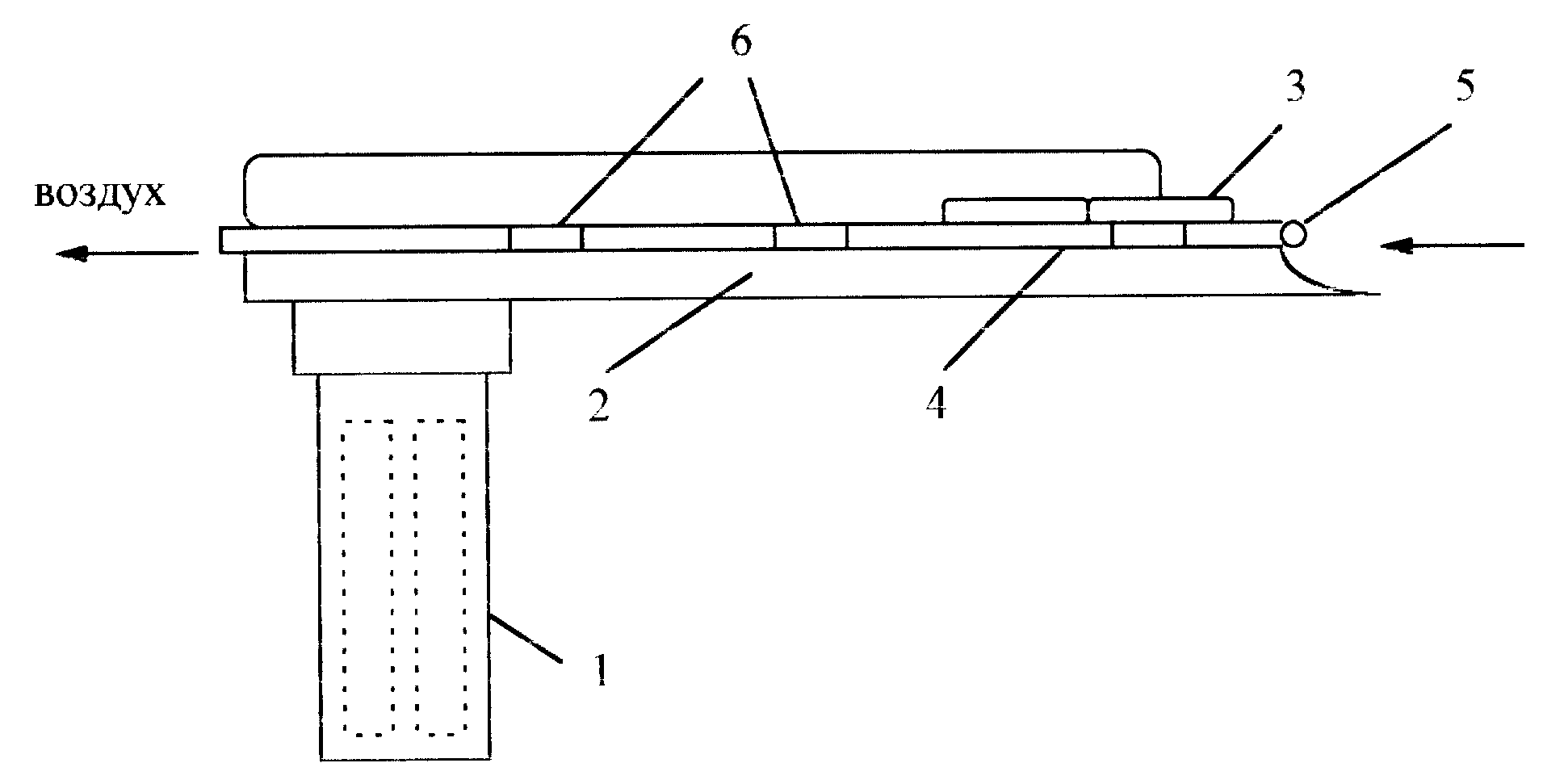
Общий вид нового ларингоскопа приведен на фиг. 1. Устройство состоит из ручки 1, содержащей во внутренней полости источник питания, и клинка 2, на латеральной поверхности источник освещения (лампочка или световод) 3 и полиэтиленовую трубку 4, срез которой (ВО) 5 размещен у края клинка 2 над источником освещения 3. Трубка 4 закреплена на поверхности клинка дужками 6 и подсоединена свободным концом к вакуум -экстрактору ( на фиг. 1 не показан).A general view of the new laryngoscope is shown in FIG. 1. The device consists of a handle 1, containing a power source in the inner cavity, and a blade 2, on the lateral surface a light source (bulb or light guide) 3 and a polyethylene tube 4, a slice of which (BO) 5 is located at the edge of the blade 2 above the light source 3 The tube 4 is fixed on the surface of the blade by the arms 6 and is connected with its free end to a vacuum extractor (not shown in Fig. 1).
Практика показала, что при использовании стандартного инструмента диаметр трубки 4 берется 3-8 мм, ширина дужек 5 мм, расстояние между дужками - 3-5 смPractice has shown that when using a standard tool, the diameter of the tube 4 is taken 3-8 mm, the width of the arches is 5 mm, the distance between the arches is 3-5 cm
Устройство работает следующим образом. При выполнении прямой ларингоскопии с ходе интубации трахеи врач предварительно подключает к трубке 4 вакуум-насос, при необходимости вставляет наконечник и включает источник освещения 3, берет его в левую руку и вводит конец клинка 2 в глотку пациента. Отсасывающий поток через отверстие ВО 5 и трубку 4 позволяет отсасывать жидкость с поверхности задней стенки глотки и прямо из входа в пищевод прицельно одной левой рукой под контролем освещения и зрения при возникновении регургитации.The device operates as follows. When performing direct laryngoscopy during tracheal intubation, the doctor pre-connects a vacuum pump to tube 4, if necessary inserts a tip and turns on light source 3, takes it into the left hand and inserts the end of blade 2 into the patient's throat. The suction stream through the hole VO 5 and the tube 4 allows you to suck the fluid from the surface of the back wall of the pharynx and directly from the entrance to the esophagus with one aimed left hand under the control of lighting and vision when regurgitation occurs.
Новый ларингоскоп удобен при применении, его обработка и дезинфекция проводится по стандартным методикам.The new laryngoscope is convenient to use, its processing and disinfection is carried out according to standard methods.
Ларингоскоп А.А. Кукушкина успешно прошел испытания при проведении более 100 операций и рекомендован Комитетом по здравоохранению Администрации С Петербурга для использования в медицинских учреждениях города.Laryngoscope A.A. Kukushkina successfully passed tests in more than 100 operations and was recommended by the Health Committee of the Administration of St. Petersburg for use in medical institutions of the city.
Claims (6)
Priority Applications (1)
| Application Number | Priority Date | Filing Date | Title |
|---|---|---|---|
| RU98117170/20U RU9699U1 (en) | 1998-09-11 | 1998-09-11 | LARINGOSCOPE A.A. KUKUSHKINA |
Applications Claiming Priority (1)
| Application Number | Priority Date | Filing Date | Title |
|---|---|---|---|
| RU98117170/20U RU9699U1 (en) | 1998-09-11 | 1998-09-11 | LARINGOSCOPE A.A. KUKUSHKINA |
Publications (1)
| Publication Number | Publication Date |
|---|---|
| RU9699U1 true RU9699U1 (en) | 1999-05-16 |
Family
ID=48271395
Family Applications (1)
| Application Number | Title | Priority Date | Filing Date |
|---|---|---|---|
| RU98117170/20U RU9699U1 (en) | 1998-09-11 | 1998-09-11 | LARINGOSCOPE A.A. KUKUSHKINA |
Country Status (1)
| Country | Link |
|---|---|
| RU (1) | RU9699U1 (en) |
-
1998
- 1998-09-11 RU RU98117170/20U patent/RU9699U1/en active
Similar Documents
| Publication | Publication Date | Title |
|---|---|---|
| US7500948B2 (en) | Dual blade laryngoscope with esophageal obturator | |
| US4126127A (en) | Suctioning/oxygenating laryngoscope blade | |
| US4947829A (en) | Modular blade laryngoscope | |
| JP2016527024A (en) | Medical device and method of using the medical device | |
| US4221220A (en) | Surgical suction apparatus | |
| US7608040B1 (en) | Device to aid in placing tracheal tubes | |
| US6955645B1 (en) | Universal modular glottiscope system having intra-wall channels for vocal fold microsurgery or orotracheal intubation | |
| WO2019153945A1 (en) | Improved visual trachea cannula | |
| RU9699U1 (en) | LARINGOSCOPE A.A. KUKUSHKINA | |
| CN112998899B (en) | Experimental animal trachea instillator | |
| CN204744089U (en) | Medical direct laryngoscope piece | |
| CN209405433U (en) | Difficulty in opening mouth oral trachea cannula soft lens protects Occluding device | |
| CN218739795U (en) | Oral cavity fixer | |
| CN205698802U (en) | A kind of tracheal intubation tube core and tracheal intubation | |
| CN214857231U (en) | Novel detachable throat abscess cutting and discharging device | |
| CN206167571U (en) | Visual nasopharynx air vent | |
| CN221450582U (en) | Ventilated electronic bronchoscope | |
| CN212788457U (en) | Disposable visual laryngoscope lens with suction and oxygen uptake functions | |
| CN212592036U (en) | Laryngoscope for trachea cannula convenient to use | |
| CN214908608U (en) | Rat and mouse trachea instillation device | |
| CN218652692U (en) | Sputum suction tube | |
| US10638924B2 (en) | Laryngoscope device | |
| CN220070381U (en) | Tracheal intubation system capable of freely rotating video | |
| CN215995194U (en) | Disposable stomach tube trachea cannula fixer | |
| CN211534358U (en) | Laryngoscope lens capable of attracting video |