RU91431U1 - HYDRAULIC STAND FOR TESTING DEEP-WATER HOUSING CASES - Google Patents
HYDRAULIC STAND FOR TESTING DEEP-WATER HOUSING CASES Download PDFInfo
- Publication number
- RU91431U1 RU91431U1 RU2009136879/22U RU2009136879U RU91431U1 RU 91431 U1 RU91431 U1 RU 91431U1 RU 2009136879/22 U RU2009136879/22 U RU 2009136879/22U RU 2009136879 U RU2009136879 U RU 2009136879U RU 91431 U1 RU91431 U1 RU 91431U1
- Authority
- RU
- Russia
- Prior art keywords
- seal
- working fluid
- hydraulic
- test
- tank
- Prior art date
Links
Landscapes
- Examining Or Testing Airtightness (AREA)
- Testing Resistance To Weather, Investigating Materials By Mechanical Methods (AREA)
Abstract
1. Гидравлический стенд для испытаний корпусов глубоководных аппаратов, содержащий герметичный резервуар с крышкой и уплотнением, фланец с уплотнением для герметизации торца испытуемого изделия, средства для подачи рабочей жидкости в резервуар и средства контроля параметров, отличающийся тем, что он снабжен вторым фланцем с уплотнением для герметизации второго торца испытуемого изделия, центральной стойкой между упомянутыми фланцами и заглушками для герметизации боковых отверстий испытуемого изделия. ! 2. Стенд по п.1, отличающийся тем, что рабочая жидкость в резервуаре подкрашена, например перманганатом калия.1. A hydraulic test bench for deep-sea vessel housings, comprising a sealed reservoir with a lid and a seal, a flange with a seal to seal the end of the test product, means for supplying working fluid to the reservoir, and means for controlling parameters, characterized in that it is equipped with a second flange with a seal for sealing the second end of the test article, a central strut between said flanges and plugs to seal the side openings of the test article. ! 2. The stand according to claim 1, characterized in that the working fluid in the tank is tinted, for example, potassium permanganate.
Description
Полезная модель относится к испытательной технике, а именно к оборудованию для испытаний на герметичность и прочность и может быть использована для проведения гидравлических испытаний.The utility model relates to testing equipment, namely, equipment for testing for tightness and strength and can be used for hydraulic tests.
Цель полезной модели - расширение функциональных возможностей и повышение достоверности результатов испытаний.The purpose of the utility model is to expand the functionality and increase the reliability of test results.
Уровень техникиState of the art
Известны способы контроля герметичности и устройства для их осуществления, заключающиеся в погружении полых изделий в жидкость, повышение в них давления с последующим визуальным контролем появления пузырьков (А.С. СССР №93842, Класс 42 k, 3001; 53 b, 3, 1951 г., опубл. Бюл. №6, 1952 г.) [1], (А.С. СССР №307296, М.Кл. G01M 3/06, опубл. 1971.01.01) [2], (А.С. СССР №1465730, МКИ4 G01M 3/06, 1987 г., опубл. Бюл. №10, 1989 г.) [3], (А.С. СССР №1474494, МКИ4 G01M 3/06, 1987 г., опубл. Бюл. №15, 1989 г.) [4], (А.С. СССР №1741000, МКИ5 G01M 3/06, 1990 г., опубл. Бюл. №22, 1992 г.) [5], (А.С. СССР №1820262, МКИ5 G01M 3/06, 1990 г., опубл. Бюл. №21, 1993 г.) [6], (Патент РФ №2090851, МКИ6 G01M 3/06, 1994 г., опубл. 1997.09.20) [7], (Патент РФ №2175118, МПК7 G01M 3/00, 1999 г., опубл. 2001.10.20) [8].Known methods of tightness control and devices for their implementation, which include immersing hollow articles in a liquid, increasing the pressure in them, followed by visual inspection of the appearance of bubbles (AS USSR No. 93842, Class 42 k, 30 01 ; 53 b, 3, 1951 published by Bull. No. 6, 1952) [1], (A.S. USSR No. 307296, M. C. G01M 3/06, published 1971.01.01) [2], (A.S. USSR No. 1465730, MKI 4 G01M 3/06, 1987, publ. Bull. No. 10, 1989) [3], (AS USSR No. 1474494, MKI 4 G01M 3/06, 1987 , publ. Bull. No. 15, 1989) [4], (AS USSR No. 1741000, MKI 5 G01M 3/06, 1990, publ. Bull. No. 22, 1992) [5] , (A.S. USSR No. 1820262, MKI 5 G01M 3/06, 1990, publ. Bull. No. 21, 1993) [6], (RF Patent No. 2090851, MKI 6 G01M 3/06, 1994, published 1997.09.20) [7], (RF Patent No. 2175118, IPC 7 G01M 3/00, 1999, published 2001.10.20) [8] .
Недостатком известных способов и устройств является невозможность проведения наружных гидравлических испытаний.A disadvantage of the known methods and devices is the inability to conduct external hydraulic tests.
Известны устройства для гидравлического испытания труб на герметичность, принцип действия которых заключается в заполнении испытываемой трубы жидкостью, создание в ней необходимого давления, выдержка под этим давлением установленное время и контроль герметичности (А.С. СССР №667844, МКИ2 G01M 3/08, 1977 г., опубл. Бюл. №22, 1979 г.) [9], (А.С. СССР №728009, МКИ2 G01M 3/02, 1978 г., опубл. Бюл. №14, 1980 г.) [10], (Патент РФ №2097725, МКИ6 G01M 3/02, 1995 г., опубл. 1997.11.27) [11], (Патент РФ №2184946, МПК7 G01M 3/08, 2001 г., опубл. 2002.07.10) [12].Known devices for hydraulic testing of pipes for leaks, the principle of which is to fill the test pipe with liquid, creating the necessary pressure in it, holding the set time under this pressure and checking the tightness (AS USSR No. 667844, MKI 2 G01M 3/08, 1977, publ. Bull. No. 22, 1979) [9], (AS USSR No. 728009, MKI 2 G01M 3/02, 1978, publ. Bull. No. 14, 1980) [10], (RF Patent No. 2097725, MKI 6 G01M 3/02, 1995, publ. 1997.11.27) [11], (RF Patent No. 2184946, IPC 7 G01M 3/08, 2001, publ. 2002.07.10) [12].
Недостатками известных устройств являются сложность конструкции и невозможность проведения испытаний наружным гидростатическим давлением.The disadvantages of the known devices are the complexity of the design and the inability to test external hydrostatic pressure.
Известна система для обеспечения предварительной проверки герметичности трубопроводов, перед подачей в них рабочей среды, содержащая регулятор давления газа наддува, расходомер, сигнализатор давления газа, исполнительные органы открытия клапана наддува и устройство отображения информации (Патент Великобритании №1376236, Кл. G01S 3/02, 1974 г.) [13].A known system for providing a preliminary check of the tightness of pipelines before supplying a working medium to them, comprising a boost gas pressure regulator, a flow meter, a gas pressure switch, boost valve opening actuators and an information display device (UK Patent No. 1376236, Cl. G01S 3/02, 1974) [13].
Герметичность замкнутого участка трубопровода проверяется следующим образом.The tightness of the closed section of the pipeline is checked as follows.
Сжатый газ через стабилизированный регулятор давления газа наддува, через расходомер и открытый клапан наддува заполняет проверяемый участок трубопровода. Большая негерметичность определяется по установившемуся показанию расходомера. Если негерметичность меньше чувствительности расходомера, то она определяется при закрытом клапане наддува по снижению показаний за фиксированный промежуток времени прибора измерения давления, который наблюдается на устройстве отображения информации.Compressed gas through a stabilized boost gas pressure regulator, through a flow meter and an open boost valve fills the tested section of the pipeline. Large leakage is determined by the steady flow meter reading. If the leakage is less than the sensitivity of the flowmeter, then it is determined when the boost valve is closed to reduce readings over a fixed period of time of the pressure measuring device, which is observed on the information display device.
Недостатками известной системы, при использовании ее для заявляемой цели, являются сложность конструкции обусловленная наличием радио-электронных блоков, а также невозможность проведения наружных гидравлических испытаний.The disadvantages of the known system, when used for the claimed purpose, are the design complexity due to the presence of radio-electronic units, as well as the inability to conduct external hydraulic tests.
За прототип, как наиболее близкий к заявляемому, выбран гидравлический стенд для испытания глубоководных модулей по Патенту РФ №2025705, МПК5 G01N 3/10, 1991 г., опубл. 30.12.1994 [14].For the prototype, as the closest to the claimed one, a hydraulic test bench for testing deep-sea modules according to the RF Patent No. 2025705, IPC 5 G01N 3/10, 1991, publ. 12/30/1994 [14].
Стенд - прототип содержит, герметичный резервуар с крышкой и уплотнением, фланец с уплотнением для герметизации испытуемого изделия, средства для подачи рабочей жидкости в резервуар и средства контроля параметров.The prototype stand contains, a sealed tank with a lid and a seal, a flange with a seal to seal the test product, means for supplying working fluid to the tank and means for monitoring parameters.
Стенд - прототип работает следующим образом.Stand - prototype works as follows.
Устанавливают модуль в резервуар, герметизируют нижний открытый торец испытуемого изделия фланцем, устанавливают герметично крышку, заполняют резервуар рабочей жидкостью, и проводят испытания внешним гидростатическим давлением.Install the module in the tank, seal the bottom open end of the test product with a flange, seal the lid, fill the tank with working fluid, and test with external hydrostatic pressure.
Недостатками стенда - прототипа являются:The disadvantages of the stand prototype are:
- невозможность проведения испытаний модулей (корпусов) с открытыми верхним и нижним торцами из-за наличия только одного фланца с уплотнением;- the impossibility of testing modules (cases) with open upper and lower ends due to the presence of only one flange with a seal;
- недостоверность результатов испытаний на герметичность из-за невозможности различения влаги конденсата от влаги микропротечек.- the reliability of the leak test results due to the impossibility of distinguishing condensate moisture from micro leakage moisture.
Цель полезной модели - расширение функциональных возможностей и повышение достоверности результатов испытаний.The purpose of the utility model is to expand the functionality and increase the reliability of test results.
Указанная цель достигается тем, что гидравлический стенд для испытаний корпусов глубоководных аппаратов, содержащий герметичный резервуар с крышкой и уплотнением, фланец с уплотнением для герметизации торца испытуемого изделия, средства для подачи рабочей жидкости в резервуар и средства контроля параметров, снабжен вторым фланцем с уплотнением для герметизации второго торца испытуемого изделия, центральной стойкой между упомянутыми фланцами, и заглушками для герметизации боковых отверстий испытуемого изделия, а рабочая жидкость в резервуаре подкрашена, например перманганатом калия.This goal is achieved in that the hydraulic test bench for the hulls of deep-sea apparatus, containing a sealed reservoir with a lid and a seal, a flange with a seal to seal the end face of the test product, means for supplying working fluid to the reservoir and means for monitoring parameters, is equipped with a second flange with a seal for sealing the second end of the test product, a central rack between the flanges, and plugs for sealing the side openings of the test product, and the working fluid in p The reservoir is tinted, for example with potassium permanganate.
Технический результат при осуществлении полезной модели заключается в возможности проведения испытаний корпусов с открытыми верхним и нижним торцами и отверстиями на боковой поверхности, т.е. в расширении функциональных возможностей, а также в повышении достоверности результатов испытаний на герметичность обеспечением различения влаги конденсата внутри изделия от влаги микропротечек, путем подкраски рабочей жидкости в резервуаре.The technical result in the implementation of the utility model is the possibility of testing the cases with open upper and lower ends and holes on the side surface, i.e. to expand the functionality, as well as to increase the reliability of the leak test results by providing a distinction between condensate moisture inside the product and micro leakage moisture, by tinting the working fluid in the tank.
Раскрытие и осуществление полезной моделиDisclosure and implementation of a utility model
Задача, на решение которой направлена полезная модель заключается в следующем.The problem to which the utility model is directed is as follows.
В различных изделиях, например в глубоководных аппаратах применяются различные по конструкции корпуса. Для специальных видов изделий используют корпуса из хромоникелевой стали 12Х18Н10Т по ГОСТ 7350-77 «Сталь тонколистовая коррозионно-стойкая, жаростойкая и жаропрочная. Технические условия».In various products, for example in deep-sea vehicles, hulls of various designs are used. For special types of products, cases made of chromium-nickel steel 12X18H10T are used in accordance with GOST 7350-77 “Steel, sheet steel, corrosion-resistant, heat-resistant and heat-resistant. Technical conditions. "
С целью снижения материалоемкости и трудоемкости корпуса изготавливают сборными из отдельных составных частей с последующей сваркой по ГОСТ 14771-76 «Дуговая сварка в защитном газе. Соединения сварные. Основные типы, конструктивные элементы и размеры».In order to reduce the material consumption and labor intensity of the body, they are made prefabricated from separate components with subsequent welding according to GOST 14771-76 “Arc welding in protective gas. Welded joints. Basic types, structural elements and dimensions. ”
После сварки и механической обработки корпусов их необходимо проверить на герметичность и прочность, т.е. проверить герметичность и прочность сварных швов наружным гидростатическим давлением 5,85-6,8 МПа (60-70 кгс/см2) в течение 1-2 часов.After welding and machining of the cases, they must be checked for leaks and strength, i.e. check the tightness and strength of the welds with an external hydrostatic pressure of 5.85-6.8 MPa (60-70 kgf / cm 2 ) for 1-2 hours.
Корпус устанавливается между модулями глубоководного аппарата и комплектуется входящими блоками поэтому его торцы открыты для электрического и гидравлического (система жидкостного охлаждения) подключения, а на боковой поверхности имеются отверстия для герметичных элементов конструкции.The housing is installed between the modules of the deep-sea vehicle and is equipped with incoming units; therefore, its ends are open for electrical and hydraulic (liquid cooling system) connections, and there are holes on the side surface for sealed structural elements.
Конкретный корпус представляет собой полое тело, состоящее из 12 вертикальных стоек в виде пластин 155×240×40 мм с отверстиями диаметром 50 мм и горизонтальных верхнего и нижнего оснований диаметром 700 мм и толщиной 40 мм с центральными отверстиями диаметром 500 мм, канавками на диаметре 585 мм шириной 15 мм и глубиной 7 мм для установки уплотнений в виде колец диаметром 600 мм с прямоугольным сечением 10×10 мм из резины ИРП - 3012 по ТУ38-005-924-84 и 18 отверстиями M12 на диаметре 678 мм для скрепления со смежными модулями глубоководного аппарата болтами M12×75 по ГОСТ 7798-70, шайбами 12 по ГОСТ 10450-78 и пружинными шайбами 12.65Г по ГОСТ 6402-70 с моментом затяжки 8 кГм, торцевые поверхности и канавки отшлифованы с параметром шероховатости Ra 1,6, при этом пластины образуют полую правильную призму с двенадцатиугольным основанием и открытыми торцами.The concrete case is a hollow body consisting of 12 vertical posts in the form of plates 155 × 240 × 40 mm with holes with a diameter of 50 mm and horizontal upper and lower bases with a diameter of 700 mm and a thickness of 40 mm with central holes with a diameter of 500 mm and grooves at a diameter of 585 15 mm wide and 7 mm deep for mounting seals in the form of rings with a diameter of 600 mm with a rectangular section of 10 × 10 mm from IRP rubber - 3012 according to TU38-005-924-84 and 18 M12 holes on a diameter of 678 mm for fastening with adjacent modules deep-sea apparatus with bolts M12 × 75 in accordance with GOST 7798-70, washers 12 according to GOST 10450-78 and spring washers 12.65G according to GOST 6402-70 with a tightening torque of 8 kgm, the end surfaces and grooves are ground with a roughness parameter of R a 1.6, while the plates form a hollow regular prism with a twelve-angle base and open ends.
Известные из уровня техники устройства не позволяют провести испытания описанного корпуса.Prior art devices do not allow testing of the described case.
Для проведения указанных испытаний необходимо герметизировать торцы и боковые отверстия корпуса верхним и нижним фланцами диаметром 700 мм толщиной 40 мм со штатными уплотнениями и заглушками, имитирующими штатные уплотнения герметичных элементов в виде круглых резиновых колец 2-53,5-3,3 по ОСТ В 38.0529-86To carry out these tests, it is necessary to seal the ends and side openings of the case with upper and lower flanges with a diameter of 700 mm and a thickness of 40 mm with standard seals and plugs that simulate standard seals of tight elements in the form of round rubber rings 2-53.5-3.3 according to OST B 38.0529 -86
При диаметре фланцев 70 см с площадью 3847 см2 и гидравлическом удельном давлении 5,85-6,8 МПа (60-70 кгс/см2) абсолютное давление на фланцы составляет в среднем 250000 кгс или 250 тс.With a diameter of 70 cm flanges with an area of 3847 cm 2 and a hydraulic specific pressure of 5.85-6.8 MPa (60-70 kgf / cm 2 ), the absolute pressure on the flanges averages 250,000 kgf or 250 tf.
Изготавливать толстостенные фланцы неэкономично, поэтому для исключения повреждения отшлифованных поверхностей корпуса при возможных касаниях от прогибов фланцев под действием гидравлического давления в конструкции целесообразно применить фланцы диаметром 700 мм, толщиной 40 мм, с креплением к корпусу, аналогичным креплению на объекте, а также ввести центральную стойку диаметром 120 мм и высотой 300 мм установить ее между упомянутыми верхним и нижним фланцами и закрепить болтом с резиновым уплотнением.It is not economical to produce thick-walled flanges, therefore, to avoid damage to the polished surfaces of the casing when it is possible to touch the deflections of the flanges under the influence of hydraulic pressure, it is advisable to use flanges with a diameter of 700 mm, 40 mm thick, with a fastening to the casing, similar to mounting on an object, and also introduce a central rack with a diameter of 120 mm and a height of 300 mm, install it between the aforementioned upper and lower flanges and secure it with a rubber seal bolt.
Кроме того, во время проведения испытаний на внутренних стенках корпуса и герметизирующих фланцев возможно появление влаги конденсата, которую можно отличить от влаги при больших протечках, однако при микропротечках различение влаги конденсата и влаги от протечек невозможно, что не позволяет получить достоверные результаты испытаний.In addition, during testing on the inner walls of the housing and sealing flanges, condensation moisture may appear, which can be distinguished from moisture with large leaks, however, with micro-leaks, it is impossible to distinguish condensate moisture and moisture from leaks, which does not allow reliable test results.
Устранение этого недостатка может быть достигнуто подкрашиванием рабочей жидкости в резервуаре, например перманганатом калия по ГОСТ 20490-75.The elimination of this disadvantage can be achieved by tinting the working fluid in the tank, for example, potassium permanganate according to GOST 20490-75.
Для проведения испытаний целесообразно также применить средства для подачи рабочей жидкости в виде гидронасоса собственного изготовления, создающего давление в замкнутом объеме до 19,4 МПа (200 кгс/см2), резервуар для рабочей жидкости в виде гидравлического бака собственного изготовления с запорными элементами, соединенного с водяной магистралью и гидронасосом стальными трубопроводами с наружным диаметром 20 мм и толщиной стенки 3 мм по ГОСТ 8734-75, рассчитанными на максимальное давление 19,4 МПа (200 кгс/см2), а также укомплектовать гидронасос и резервуар для рабочей жидкости средствами контроля параметров (давления) в виде манометров МТП -200 по ГОСТ 2405-72, рассчитанных на максимальное давление 19,4 МПа (200 кгс/см2).For testing it is also advisable to use means for supplying a working fluid in the form of a self-made hydraulic pump, creating a pressure in a closed volume of up to 19.4 MPa (200 kgf / cm 2 ), a working fluid reservoir in the form of a self-made hydraulic tank with shut-off elements connected a water line and the hydraulic pump steel pipes with an outer diameter of 20 mm and a wall thickness of 3 mm according to GOST 8734-75, designed for maximum pressure of 19.4 MPa (200 kgf / cm 2), and the complement hydropump a hydraulic fluid tank by means of control parameters (pressure) as a gauge MMP -200 GOST 2405-72, designed for maximum pressure of 19.4 MPa (200 kgf / cm 2).
Цель полезной модели - расширение функциональных возможностей и повышение достоверности результатов испытаний.The purpose of the utility model is to expand the functionality and increase the reliability of test results.
Технический результат при осуществлении полезной модели заключается в возможности проведения испытаний корпусов с открытыми верхним и нижним торцами и отверстиями на боковой поверхности, т.е. в расширении функциональных возможностей, а также в повышении достоверности результатов испытаний на герметичность обеспечением различения влаги конденсата внутри изделия от влаги микропротечек, путем подкраски рабочей жидкости в резервуаре.The technical result in the implementation of the utility model is the possibility of testing the cases with open upper and lower ends and holes on the side surface, i.e. to expand the functionality, as well as to increase the reliability of the leak test results by providing a distinction between condensate moisture inside the product and micro leakage moisture, by tinting the working fluid in the tank.
Краткое описание чертежейBrief Description of the Drawings
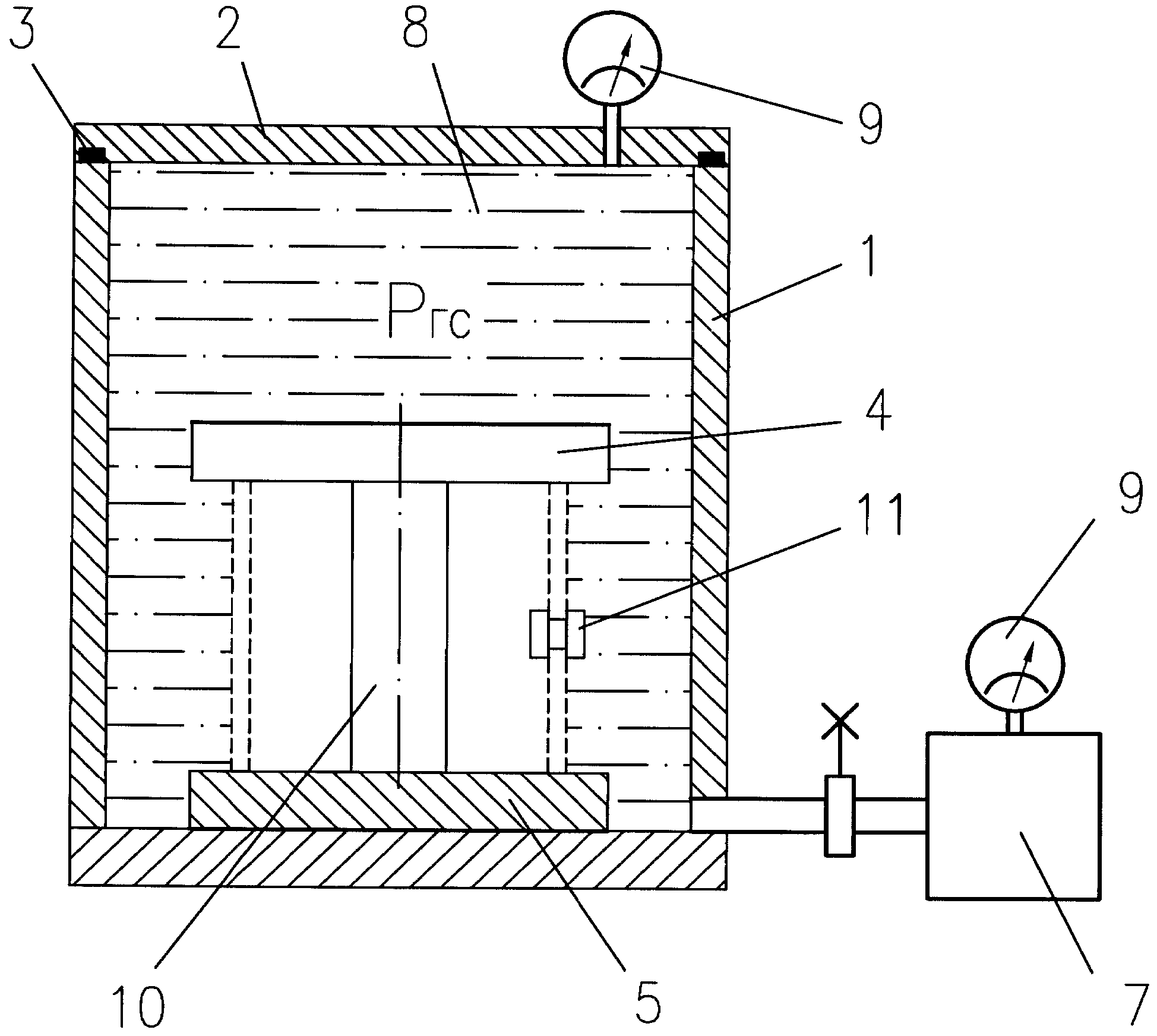
На фиг.1 изображена функциональная схема гидравлического стенда для испытаний корпусов глубоководных аппаратов; на фиг.2 - гидравлический стенд, общий вид; на фиг.3 - корпус с герметичными уплотнениями, штрих - пунктирными линиями показан корпус, гидростатическое давление обозначено Ргс.Figure 1 shows a functional diagram of a hydraulic stand for testing the hulls of deep-sea vehicles; figure 2 - hydraulic stand, General view; figure 3 - body with hermetic seals, dashed lines show the body, the hydrostatic pressure is designated R g .
Гидравлический стенд содержит герметичный резервуар 1 с крышкой 2 и уплотнением 3, фланцы 4 и 5 с уплотнениями 6 для герметизации торца испытуемого изделия, средства 7 для подачи рабочей жидкости 8 в резервуар 1, средства контроля параметров 9, центральную стойку 10 между фланцами 4 и 5 и заглушки 11 для герметизации боковых отверстий испытуемого изделия, при этом рабочая жидкость 8 в резервуаре подкрашена, например перманганатом калия.The hydraulic stand contains a sealed tank 1 with a cover 2 and a seal 3, flanges 4 and 5 with seals 6 for sealing the end face of the test product, means 7 for supplying the working fluid 8 to the tank 1, means for monitoring parameters 9, a central rack 10 between flanges 4 and 5 and plugs 11 for sealing the side openings of the test product, while the working fluid 8 in the tank is tinted, for example with potassium permanganate.
Работа со стендом осуществляется следующим образом:Work with the stand is as follows:
- в канавки корпуса (на чертеже не обозначен) закладывают штатные уплотнения 6;- in the grooves of the housing (not indicated in the drawing) lay standard seals 6;
- устанавливают корпус на нижний фланец 5 нижним основанием и закрепляют его болтами и шайбами (на чертеже не обозначены);- install the housing on the lower flange 5 with the lower base and fix it with bolts and washers (not shown in the drawing);
- боковые отверстия корпуса герметизируют заглушками 11;- the side openings of the housing are sealed with plugs 11;
- в центре нижнего фланца 5 устанавливают стойку 10 и закрепляют болтом с резиновым уплотнением (на чертеже не обозначены);- in the center of the lower flange 5 install the rack 10 and fix the bolt with a rubber seal (not shown in the drawing);
- на верхнее основание корпуса устанавливают верхний фланец 4 со строповочными элементами (рым - болтами M12 по ГОСТ 4751-73, на чертеже не обозначены) и закрепляют его болтами;- the upper flange 4 with the lifting elements (eyebolts - M12 bolts according to GOST 4751-73, are not indicated in the drawing) is installed on the upper case base and fixed with bolts;
- при помощи грузоподъемного механизма (на чертеже не показан) устанавливают герметизированный корпус в резервуар 1;- using a lifting mechanism (not shown in the drawing) install a sealed housing in the tank 1;
- закрывают и герметизируют резервуар 1 крышкой 2 с уплотнением 3;- close and seal the tank 1 with a cover 2 with a seal 3;
- средствами 7 подают подкрашенную рабочую жидкость 8 в резервуар 1 и создают необходимое давление, величину давления контролируют средствами 9;- means 7 serves tinted working fluid 8 in the tank 1 and create the necessary pressure, the pressure is controlled by means 9;
- выдерживают корпус под давлением установленное время;- maintain the case under pressure for a specified time;
- сбрасывают давление и извлекают герметизированный корпус из резервуара 1;- relieve pressure and remove the sealed housing from the tank 1;
- снимают с корпуса фланцы 4 и 5, стойку 10 и заглушки 11 и проверяют на отсутствие жидкости 8 внутри корпуса.- remove the flanges 4 and 5, the rack 10 and the plug 11 from the housing, and check for the absence of fluid 8 inside the housing.
Корпус считают выдержавшим испытание, если жидкость 8 внутри него не обнаружена.The case is considered to have passed the test if no fluid 8 inside is detected.
Claims (2)
Priority Applications (1)
| Application Number | Priority Date | Filing Date | Title |
|---|---|---|---|
| RU2009136879/22U RU91431U1 (en) | 2009-10-05 | 2009-10-05 | HYDRAULIC STAND FOR TESTING DEEP-WATER HOUSING CASES |
Applications Claiming Priority (1)
| Application Number | Priority Date | Filing Date | Title |
|---|---|---|---|
| RU2009136879/22U RU91431U1 (en) | 2009-10-05 | 2009-10-05 | HYDRAULIC STAND FOR TESTING DEEP-WATER HOUSING CASES |
Publications (1)
| Publication Number | Publication Date |
|---|---|
| RU91431U1 true RU91431U1 (en) | 2010-02-10 |
Family
ID=42124138
Family Applications (1)
| Application Number | Title | Priority Date | Filing Date |
|---|---|---|---|
| RU2009136879/22U RU91431U1 (en) | 2009-10-05 | 2009-10-05 | HYDRAULIC STAND FOR TESTING DEEP-WATER HOUSING CASES |
Country Status (1)
| Country | Link |
|---|---|
| RU (1) | RU91431U1 (en) |
Cited By (7)
| Publication number | Priority date | Publication date | Assignee | Title |
|---|---|---|---|---|
| CN107179247A (en) * | 2017-06-26 | 2017-09-19 | 武汉高明兰光电科技有限公司 | A kind of Scientific Research Platform of deep water l-G simulation test |
| RU2636812C2 (en) * | 2015-12-31 | 2017-11-28 | Российская Федерация, От Имени Которой Выступает Министерство Промышленности И Торговли Российской Федерации | Method of external hydrostatic load test of sheath |
| RU2701756C1 (en) * | 2019-01-28 | 2019-10-01 | Акционерное общество "Центр технологии судостроения и судоремонта" (АО "ЦТСС") | Test bench for internal pressure testing of deepwater apparatus modules |
| RU2704563C1 (en) * | 2019-03-07 | 2019-10-29 | Федеральное государственное унитарное предприятие "Крыловский государственный научный центр" | METHOD OF PERFORMANCE OF STRENGTH TESTS AND TESTING OF TIGHTNESS OF DEEP-WATER TECHNICAL FACILITY INTENDED FOR OPERATION AT DEPTHS OF UP TO 11,5 km, EXTERNAL HYDROSTATIC PRESSURE AND DEVICE FOR ITS IMPLEMENTATION |
| RU2723634C1 (en) * | 2019-12-18 | 2020-06-18 | Федеральное государственное унитарное предприятие "Крыловский государственный научный центр" | Device for performance of strength tests and tightness testing of deep-water technical facility intended for operation at depths of up to 11_5 km, external hydrostatic pressure |
| RU2741829C2 (en) * | 2019-05-13 | 2021-01-28 | Федеральное государственное казенное военное образовательное учреждение высшего образования "Военный учебно-научный центр Военно-Морского Флота "Военно-морская академия им. Адмирала Флота Советского Союза Н.Г. Кузнецова" | Method for hydraulic testing of strong hulls of deep-water equipment |
| RU2788819C1 (en) * | 2022-07-12 | 2023-01-24 | Акционерное общество "Центр технологии судостроения и судоремонта" (АО "ЦТСС") | Method for testing technological modules of deep-sea submersibles for internal pressure using a stand for testing technological modules of deep-sea submersibles for internal pressure |
-
2009
- 2009-10-05 RU RU2009136879/22U patent/RU91431U1/en not_active IP Right Cessation
Cited By (7)
| Publication number | Priority date | Publication date | Assignee | Title |
|---|---|---|---|---|
| RU2636812C2 (en) * | 2015-12-31 | 2017-11-28 | Российская Федерация, От Имени Которой Выступает Министерство Промышленности И Торговли Российской Федерации | Method of external hydrostatic load test of sheath |
| CN107179247A (en) * | 2017-06-26 | 2017-09-19 | 武汉高明兰光电科技有限公司 | A kind of Scientific Research Platform of deep water l-G simulation test |
| RU2701756C1 (en) * | 2019-01-28 | 2019-10-01 | Акционерное общество "Центр технологии судостроения и судоремонта" (АО "ЦТСС") | Test bench for internal pressure testing of deepwater apparatus modules |
| RU2704563C1 (en) * | 2019-03-07 | 2019-10-29 | Федеральное государственное унитарное предприятие "Крыловский государственный научный центр" | METHOD OF PERFORMANCE OF STRENGTH TESTS AND TESTING OF TIGHTNESS OF DEEP-WATER TECHNICAL FACILITY INTENDED FOR OPERATION AT DEPTHS OF UP TO 11,5 km, EXTERNAL HYDROSTATIC PRESSURE AND DEVICE FOR ITS IMPLEMENTATION |
| RU2741829C2 (en) * | 2019-05-13 | 2021-01-28 | Федеральное государственное казенное военное образовательное учреждение высшего образования "Военный учебно-научный центр Военно-Морского Флота "Военно-морская академия им. Адмирала Флота Советского Союза Н.Г. Кузнецова" | Method for hydraulic testing of strong hulls of deep-water equipment |
| RU2723634C1 (en) * | 2019-12-18 | 2020-06-18 | Федеральное государственное унитарное предприятие "Крыловский государственный научный центр" | Device for performance of strength tests and tightness testing of deep-water technical facility intended for operation at depths of up to 11_5 km, external hydrostatic pressure |
| RU2788819C1 (en) * | 2022-07-12 | 2023-01-24 | Акционерное общество "Центр технологии судостроения и судоремонта" (АО "ЦТСС") | Method for testing technological modules of deep-sea submersibles for internal pressure using a stand for testing technological modules of deep-sea submersibles for internal pressure |
Similar Documents
| Publication | Publication Date | Title |
|---|---|---|
| RU91431U1 (en) | HYDRAULIC STAND FOR TESTING DEEP-WATER HOUSING CASES | |
| CN102322570B (en) | Underwater gas transportation pipeline leakage detection experiment platform | |
| CN207263399U (en) | A kind of multistation valve airtight detection apparatus | |
| CN103207141A (en) | Hydrogen sulfide resistant stress corrosion cracking and bending test device | |
| CN107884008B (en) | Method for testing sealing performance of metal hose under axial tension and corrosion state | |
| CN104122048A (en) | High-pressure gas tightness detection system | |
| RU2666161C1 (en) | Method of testing tube steels on stress corrosion cracking and device for its implementation | |
| CN107402120B (en) | Pipeline clamping device and quality detection method of sealing clamp | |
| CN204314033U (en) | Pipe flange compactedness test macro | |
| CA2592111A1 (en) | Fluid containment element leak detection apparatus and method | |
| CN203981365U (en) | A kind of high pressure air tightness detection system | |
| CN203023080U (en) | Portable performance test device for submerged pump | |
| CN203216822U (en) | Anti-hydrogen sulfide stress corrosion cracking bending test device | |
| CN220230865U (en) | Detection device for detecting air tightness of pipeline | |
| CN103674709A (en) | Apparatus for testing performance of external safety relief valve of tank container | |
| CN115435983A (en) | External pressure type sealing performance test device | |
| CN206311278U (en) | Safety valve leakage test blanking cover | |
| CN202252872U (en) | Underwater gas transmission pipeline leakage detection performance evaluating experimental platform | |
| RU2238212C1 (en) | Connecting chamber for testing portlights | |
| US5767393A (en) | Apparatus and method for detecting leaks in tanks | |
| CN107656035B (en) | Permeation and humidity diffusion test device | |
| CN210716988U (en) | Coal mine underground water supply pipeline leakage rapid detection device | |
| CN107638650B (en) | Cart type fire extinguisher cylinder pressure alternation and explosion test device | |
| CN210293584U (en) | Power station water system equipment flange seals and detects analogue means | |
| CN208568214U (en) | A kind of vacuum type leak detection apparatus and system |
Legal Events
| Date | Code | Title | Description |
|---|---|---|---|
| MM1K | Utility model has become invalid (non-payment of fees) |
Effective date: 20101006 |