RU79910U1 - SET OF ELEMENTS FOR FIXING FACING PANELS AND A CARRYING FRAME OF A HINGED VENTED FACADE OF A BUILDING ON ITS BASIS - Google Patents
SET OF ELEMENTS FOR FIXING FACING PANELS AND A CARRYING FRAME OF A HINGED VENTED FACADE OF A BUILDING ON ITS BASIS Download PDFInfo
- Publication number
- RU79910U1 RU79910U1 RU2008134457/22U RU2008134457U RU79910U1 RU 79910 U1 RU79910 U1 RU 79910U1 RU 2008134457/22 U RU2008134457/22 U RU 2008134457/22U RU 2008134457 U RU2008134457 U RU 2008134457U RU 79910 U1 RU79910 U1 RU 79910U1
- Authority
- RU
- Russia
- Prior art keywords
- connecting elements
- shelves
- parts
- bearing
- brackets
- Prior art date
Links
Landscapes
- Finishing Walls (AREA)
Abstract
Полезная модель относится к области строительства и преимущественно может быть использована в конструкциях навесных вентилируемых фасадов зданий и сооружений. Комплект содержит несущие кронштейны, выполненные из двух Г-образных по форме частей с возможностью скрепления их своими полками с помощью соединительных элементов, причем первые части несущих кронштейнов выполнены с возможностью установки своей полкой на стене здания посредством соединительных элементов, несущие направляющие в виде протяженных П-образных профилей с отогнутыми наружу боковыми сторонами с образованием полок для установки облицовочных панелей, выполненные с возможностью установки наружной поверхностью своей центральной полки на вторых полках вторых частей несущих кронштейнов, и соединительные элементы. Несущий каркас содержит несущие кронштейны, выполненные из двух Г-образных по форме частей, скрепленных своими полками с помощью соединительных элементов, причем первые части каждого несущего кронштейна установлены одной своей полкой на стене здания посредством соединительных элементов, и несущие направляющие в виде протяженных П-образных профилей с отогнутыми наружу боковыми сторонами с образованием полок для установки облицовочных панелей, которые вертикально установлены наружной поверхностью своей центральной полки на полках вторых частей несущих кронштейнов. Полезная модель обеспечивает снижение стоимости несущего каркаса навесного вентилируемого фасада и комплекта его элементов, а также упрощение монтажа. 2 н.п. ф-лы, 12 з.п. ф-лы, 2 илл.The utility model relates to the field of construction and can mainly be used in the construction of ventilated facades of buildings and structures. The kit contains load-bearing brackets made of two L-shaped parts with the possibility of fastening them with their own shelves using connecting elements, the first parts of the load-bearing brackets made with the possibility of mounting their shelf on the wall of the building by means of connecting elements, bearing guides in the form of extended П- shaped profiles with laterally bent outward sides with the formation of shelves for installation of facing panels, made with the possibility of installing the outer surface of its central the first shelf on the second shelves of the second parts of the supporting brackets, and connecting elements. The supporting frame contains supporting brackets made of two L-shaped parts fastened by their shelves with the help of connecting elements, the first parts of each bearing bracket being installed with one of their own shelves on the building wall by means of connecting elements, and bearing guides in the form of extended U-shaped profiles with outwardly curved sides to form shelves for installing cladding panels that are vertically mounted with the outer surface of their central shelf on the shelves of other parts of the supporting brackets. The utility model provides a reduction in the cost of the supporting frame of the hinged ventilated facade and a set of its elements, as well as simplification of installation. 2 n.p. f-ly, 12 z.p. f-ly, 2 ill.
Description
Полезная модель относится к области строительства и преимущественно может быть использована в конструкциях навесных вентилируемых фасадов зданий и сооружений.The utility model relates to the field of construction and can mainly be used in the construction of ventilated facades of buildings and structures.
Известны комплекты металлических элементов для крепления облицовочных панелей навесного вентилируемого фасада (RU 22798 U1, 2002; RU 26061 U1, 2002; RU 26062 U1, 2002; RU 26236 U1, 2002; RU 26237 U1, 2002; RU 60556 U1, 2007), которые в общей для них части содержат несущие кронштейны, имеющие С-образный профиль и предназначенные для крепления к стене здания, опорные кронштейны, имеющие С-образный профиль и предназначенные для крепления к стене здания, направляющие, имеющие П-образный профиль, снабженные элементами жесткости или взаимодействия с другими элементами комплекта (ребрами жесткости, выступами, пазами, лапками, отбортовками, полками) и предназначенные для крепления облицовочных панелей, и элементы соединения в виде болтов с гайками, заклепок или самонарезающих болтов.Known sets of metal elements for fastening the facing panels of the hinged ventilated facade (RU 22798 U1, 2002; RU 26061 U1, 2002; RU 26062 U1, 2002; RU 26236 U1, 2002; RU 26237 U1, 2002; RU 60556 U1, 2007), which in the common part, they contain load-bearing brackets having a C-shaped profile and intended for fastening to the wall of the building, supporting brackets having a C-shaped profile and intended for fastening to the wall of the building, guides having a U-shaped profile, equipped with stiffeners or interactions with other elements of the kit (ribs edges, protrusions, grooves, pads, flanges, shelves) and intended for fastening of facing panels, and connection elements in the form of bolts with nuts, rivets or self-tapping bolts.
Известны также комплекты металлических элементов для модульного каркаса навесного вентилируемого фасада здания (RU 57308 U1, 2006; RU 60562 U1, 2007; RU 67129 U1, 2007), которые в общей для них части содержат несущие кронштейны Г-образной формы, опорные кронштейны Г-образной формы, прижимы, выполненные с возможностью установки на несущих и опорных кронштейнах с помощью выступов и пазов и фиксации посредством заклепок, вертикальные направляющие в виде П-образных профилей с отогнутыми наружу боковыми сторонами с образованием полок для установки облицовочных панелей, которые снабжены ребром с насечками, выполненным на опорной поверхности центральной полки, и элементы соединения в виде болтов с гайками, заклепок или самонарезающих болтов.Also known are sets of metal elements for a modular frame of a hinged ventilated facade of a building (RU 57308 U1, 2006; RU 60562 U1, 2007; RU 67129 U1, 2007), which in their common part contain L-shaped supporting brackets, G- supporting brackets shaped, clamps made with the possibility of installation on the bearing and supporting brackets with the help of protrusions and grooves and fixing by means of rivets, vertical guides in the form of U-shaped profiles with laterally bent outward sides with the formation of shelves for installation of facing pa spruce, which are provided with an edge with notches formed on the supporting surface of the central shelf elements and compounds in the form of bolts and nuts, rivets or self-tapping screws.
Недостатками указанных известных комплектов являются их значительная стоимость, обусловленная сложностью профилей элементов и их металлоемкостью, а также сложность их монтажа при строительстве.The disadvantages of these known sets are their significant cost, due to the complexity of the profiles of the elements and their metal consumption, as well as the complexity of their installation during construction.
Наиболее близким по конструкции к комплекту для крепления облицовочных панелей, являющемуся предметом настоящей полезной модели, является комплект элементов для крепления облицовочных панелей системы навесных вентилируемых фасадов СИАЛ (RU 48193 U1, 2005). Указанный известный комплект, являющийся ближайшим аналогом, содержит несущие кронштейны и опорные кронштейны, которые выполнены из двух частей с возможностью их соединения посредством болтов с гайками, причем первая часть выполнена Г-образной формы и снабжена насечками, а вторая часть выполнена П-образной формы и снабжена ребром с насечками, выполненным на The closest in design to the kit for fastening the cladding panels, which is the subject of this utility model, is a set of elements for fastening the cladding panels of the system of ventilated facades SIAL (RU 48193 U1, 2005). The specified known kit, which is the closest analogue, contains bearing brackets and support brackets, which are made of two parts with the possibility of their connection by means of bolts and nuts, the first part being L-shaped and provided with notches, and the second part made U-shaped and equipped with a rib with notches made on
наружной поверхности центральной полки. Кроме того, известный комплект содержит салазки П-образной формы с Г-образными зацепами на концах и отверстиями под заклепки, выполненные с возможностью установки внутри П-образного профиля вторых частей несущих и опорных кронштейнов, и вертикальные направляющие в виде П-образных профилей с отогнутыми наружу боковыми сторонами с образованием полок для установки облицовочных панелей, которые снабжены отверстиями, выступами, пазами, каналами и насечками, а также элементы соединения в виде болтов с гайками, заклепок и анкеров.outer surface of the central shelf. In addition, the known kit contains a U-shaped slide with L-shaped hooks at the ends and rivet holes made with the possibility of installing inside the U-shaped profile of the second parts of the bearing and support brackets, and vertical guides in the form of U-shaped profiles with bent outward with the sides to form shelves for installing facing panels, which are equipped with holes, protrusions, grooves, channels and notches, as well as connection elements in the form of bolts with nuts, rivets and anchors.
Недостатками указанного известного комплекта, являющегося ближайшим аналогом, являются его значительная стоимость, обусловленная сложностью профилей элементов и их металлоемкостью, а также сложность монтажа при строительстве.The disadvantages of this known kit, which is the closest analogue, are its significant cost, due to the complexity of the profiles of the elements and their metal consumption, as well as the complexity of installation during construction.
Известны несущие каркасы навесного вентилируемого фасада здания (RU 22798 U1, 2002; RU 26061 U1, 2002; RU 26062 U1, 2002; RU 26236 U1, 2002; RU 26237 U1, 2002; RU 60556 U1, 2007), которые в общей для них части содержат несущие кронштейны, имеющие С-образный профиль и установленные на стене здания, например, с помощью дюбелей, опорные кронштейны, имеющие С-образный профиль и установленные на стене здания, например, с помощью дюбелей, и направляющие, имеющие П-образный профиль, снабженные элементами жесткости или взаимодействия с другими элементами (ребрами жесткости, выступами, пазами, лапками, отбортовками, полками), установленные вертикально на несущих кронштейнах, например, с помощью заклепок с возможностью опоры на опорные кронштейны и предназначенные для крепления облицовочных панелей.The known supporting frames of a hinged ventilated building facade (RU 22798 U1, 2002; RU 26061 U1, 2002; RU 26062 U1, 2002; RU 26236 U1, 2002; RU 26237 U1, 2002; RU 60556 U1, 2007), which are common to them the parts contain supporting brackets having a C-shaped profile and mounted on the wall of the building, for example, using dowels, support brackets having a C-shaped profile and installed on the wall of the building, for example, using dowels, and rails having a U-shaped profile equipped with stiffening elements or interacting with other elements (stiffening ribs, protrusions, grooves, paws by flanges, shelves) mounted vertically on the supporting brackets, for example, using rivets with the possibility of support on the supporting brackets and intended for fastening the facing panels.
Известны также модульные несущие каркасы навесного вентилируемого фасада здания (RU 57308 U1, 2006; RU 60562 U1, 2007; RU 67129 U1, 2007), которые в общей для них части содержат несущие кронштейны Г-образной формы с насечками, установленные на стене здания, например, с помощью анкеров, опорные кронштейны Г-образной формы с насечками, установленные на стене здания, например, с помощью анкеров, прижимы, установленные на несущих и опорных кронштейнах с помощью выступов и пазов и зафиксированные посредством заклепок, и вертикальные направляющие в виде П-образных профилей с отогнутыми наружу боковыми сторонами с образованием полок для установки облицовочных панелей, которые снабжены ребром с насечками, выполненным на опорной поверхности центральной полки и установленным на несущих и опорных кронштейнах, например, с помощью заклепок.Modular load-bearing frames of a hinged ventilated facade of a building are also known (RU 57308 U1, 2006; RU 60562 U1, 2007; RU 67129 U1, 2007), which in their common part contain L-shaped supporting brackets with notches mounted on the wall of the building, for example, using anchors, L-shaped support brackets with notches mounted on a building wall, for example, using anchors, clamps mounted on bearing and support brackets with protrusions and grooves and fixed with rivets, and vertical guides in the form of П -shaped prof ile with side bent outward to form shelves for installing facing panels, which are equipped with a notched rib made on the supporting surface of the central shelf and mounted on the supporting and supporting brackets, for example, using rivets.
Недостатками указанных известных несущих каркасов навесного вентилируемого фасада здания являются их значительная стоимость, обусловленная сложностью профилей элементов и их металлоемкостью, а также сложность их монтажа при строительстве.The disadvantages of these known load-bearing frames of the hinged ventilated facade of the building are their significant cost, due to the complexity of the profiles of the elements and their metal consumption, as well as the complexity of their installation during construction.
Наиболее близким по конструкции к несущему каркасу навесного вентилируемого фасада здания, являющемуся предметом настоящей полезной модели, является несущий каркас системы навесных вентилируемых фасадов СИАЛ (RU 48193 U1, 2005). Указанный известный несущий каркас, являющийся ближайшим аналогом, содержит группу модулей, каждый из которых содержит несущие кронштейны и опорные кронштейны, которые выполнены из двух частей и соединены друг с другом посредством болтов с гайками, причем первая часть выполнена Г-образной формы, снабжена насечками и установлена на стене здания с помощью анкера, а вторая часть выполнена П-образной формы и снабжена ребром с насечками, выполненным на наружной поверхности центральной полки. Кроме того, каждый модуль содержит салазки П-образной формы с Г-образными зацепами на концах, установленные внутри П-образного профиля вторых частей несущих и опорных кронштейнов с помощью заклепок, и направляющие в виде П-образных профилей с отогнутыми наружу боковыми сторонами с образованием полок для установки облицовочных панелей, которые снабжены отверстиями, выступами, пазами, каналами и насечками, установлены в салазках и зафиксированы в них с помощью заклепок.The closest in design to the supporting frame of the hinged ventilated facade of the building, which is the subject of this utility model, is the supporting frame of the system of suspended ventilated facades SIAL (RU 48193 U1, 2005). The specified known load-bearing frame, which is the closest analogue, contains a group of modules, each of which contains load-bearing brackets and support brackets, which are made of two parts and connected to each other by bolts with nuts, the first part being L-shaped, provided with notches and mounted on the wall of the building using an anchor, and the second part is made in a U-shape and provided with a rib with notches made on the outer surface of the central shelf. In addition, each module contains a U-shaped slide with L-shaped hooks at the ends, mounted inside the U-shaped profile of the second parts of the bearing and support brackets with rivets, and guides in the form of U-shaped profiles with laterally bent outward sides to form shelves for installing cladding panels, which are equipped with holes, protrusions, grooves, channels and notches, are installed in the rails and fixed in them with rivets.
Недостатками указанного известного несущего каркаса системы навесных вентилируемых фасадов, являющегося ближайшим аналогом, являются его значительная стоимость, обусловленная сложностью профилей элементов и их металлоемкостью, а также сложность монтажа при строительстве.The disadvantages of this known supporting frame of the system of mounted ventilated facades, which is the closest analogue, are its significant cost, due to the complexity of the profiles of the elements and their metal consumption, as well as the complexity of installation during construction.
Задачами настоящей полезной модели являются снижение стоимости несущего каркаса навесного вентилируемого фасада здания и комплекта его элементов, а также упрощение монтажа.The objectives of this utility model are to reduce the cost of the supporting frame of the hinged ventilated facade of the building and a set of its elements, as well as simplifying installation.
Поставленная задача решается, согласно настоящей полезной модели, во-первых, тем, что комплект элементов для крепления облицовочных панелей, содержащий, в соответствии с ближайшим аналогом, несущие кронштейны, выполненные из двух частей с возможностью их скрепления соединительными элементами, причем первые части каждого несущего кронштейна выполнены Г-образными по форме с возможностью установки своей первой полкой на стене здания посредством соединительных элементов, выполненные с возможностью установки на вторых частях несущих кронштейнов с помощью соединительных элементов несущие направляющие в виде протяженных П-образных профилей с отогнутыми наружу боковыми сторонами с образованием полок для установки облицовочных панелей, и соединительные элементы, отличается от ближайшего аналога тем, что каждая вторая часть несущего кронштейна выполнена Г-образной по форме с возможностью скрепления своей первой полкой со второй полкой первой части несущего кронштейна, а каждая несущая направляющая The problem is solved, according to this utility model, firstly, by the fact that a set of elements for attaching the facing panels, comprising, in accordance with the closest analogue, supporting brackets made of two parts with the possibility of fastening them with connecting elements, the first parts of each bearing the brackets are made L-shaped in shape with the possibility of installing their first shelf on the wall of the building by means of connecting elements, made with the possibility of installation on the second parts of the bearing crowns matte using connecting elements, bearing guides in the form of extended U-shaped profiles with laterally bent outward sides to form shelves for installation of facing panels, and connecting elements, differs from the closest analogue in that each second part of the bearing bracket is made L-shaped in shape with the possibility of fastening its first shelf with the second shelf of the first part of the bearing bracket, and each bearing guide
выполнена с возможностью установки наружной поверхностью своей центральной полки на вторых полках вторых частей несущих кронштейнов.made with the possibility of installing the outer surface of its Central shelf on the second shelves of the second parts of the supporting brackets.
При этом в качестве соединительных элементов для скрепления первой и второй частей несущего кронштейна он снабжен заклепками или болтами с гайками или самонарезающими болтами, в качестве соединительных элементов для установки несущей направляющей на вторых частях несущих кронштейнов он снабжен заклепками или болтами с гайками или самонарезающими болтами, а в качестве соединительных элементов для установки первой части несущего кронштейна на стене здания он снабжен анкерами или самонарезающими болтами с дюбелями.Moreover, as connecting elements for fastening the first and second parts of the bearing bracket, it is equipped with rivets or bolts with nuts or self-tapping bolts, as connecting elements for installing the bearing guide on the second parts of the bearing brackets, it is equipped with rivets or bolts with nuts or self-tapping bolts, and as connecting elements for installing the first part of the supporting bracket on the wall of the building, it is equipped with anchors or self-tapping bolts with dowels.
Кроме того, комплект снабжен опорными кронштейнами, выполненными Г-образными по форме с возможностью установки своими первыми полками с помощью соединительных элементов на стене здания, и опорными направляющими в виде протяженных Г-образных профилей, выполненными с возможностью установки одной своей полкой на вторых полках опорных кронштейнов с помощью соединительных элементов, причем в качестве соединительных элементов для установки опорного кронштейна на стене здания он снабжен анкерами или самонарезающими болтами с дюбелями, а в качестве соединительных элементов для установки опорных направляющих на опорных кронштейнах он снабжен заклепками или болтами с гайками или самонарезающими болтами.In addition, the kit is equipped with supporting brackets made L-shaped in shape with the possibility of installing their first shelves using connecting elements on the wall of the building, and supporting guides in the form of extended L-shaped profiles made with the possibility of installing one of their own shelves on the second supporting shelves brackets using connecting elements, and as connecting elements for mounting the support bracket on the wall of the building, it is equipped with anchors or self-tapping bolts with dowels, and in achestve connecting elements for mounting the support rails to the supporting bracket is provided with a riveted or bolted with bolts or self-tapping screws.
Выполнение каждой второй части несущего кронштейна комплекта элементов для крепления облицовочных панелей Г-образной по форме с возможностью скрепления своей первой полкой со второй полкой первой части несущего кронштейна, а каждой несущей направляющей с возможностью установки наружной поверхностью своей центральной полки на вторых попках вторых частей несущих кронштейнов обеспечивает, во-первых, возможность установки несущей направляющей непосредственно на второй части несущих кронштейнов без использования каких-либо сопрягающих элементов, как это предусмотрено в ближайшем аналоге, обеспечивая уменьшение количества элементов, входящих в заявляемый комплект, по отношению к ближайшему аналогу, что приводит к снижению расхода металла при его изготовлении. Во-вторых, эти отличительные признаки обеспечивают возможность использования в составе заявляемого комплекта элементов, которые имеют значительно более простой профиль, не содержащий ребер, насечек, выступов, пазов и каналов, как предусмотрено в конструкции ближайшего аналога. В результате этого снижается стоимость несущего каркаса навесного вентилируемого фасада и комплекта его элементов, а также упрощается их монтаж.The execution of each second part of the bearing bracket of the set of elements for fastening the facing panels is L-shaped in shape with the possibility of fastening its first shelf with the second shelf of the first part of the bearing bracket, and each bearing guide with the possibility of installing the outer surface of its central shelf on the second butt of the second parts of the bearing brackets provides, firstly, the ability to install the carrier rail directly on the second part of the carrier arms without the use of any mating x elements, as provided for in the closest analogue, providing a decrease in the number of elements included in the inventive kit in relation to the closest analogue, which leads to a decrease in metal consumption in its manufacture. Secondly, these distinctive features provide the possibility of using in the composition of the inventive set of elements that have a much simpler profile that does not contain ribs, notches, protrusions, grooves and channels, as provided in the design of the closest analogue. As a result of this, the cost of the supporting frame of the hinged ventilated facade and a set of its elements is reduced, and their installation is also simplified.
Поставленная задача решается, согласно настоящей полезной модели, во-вторых, также тем, что несущий каркас навесного вентилируемого фасада здания, The problem is solved, according to this utility model, and secondly, also by the fact that the supporting frame of the hinged ventilated facade of the building,
содержащий, в соответствии с ближайшим аналогом, несущие кронштейны, выполненные из двух частей, скрепленных соединительными элементами, причем первые части каждого несущего кронштейна выполнены Г-образными по форме и установлены своей первой полкой на стене здания посредством соединительных элементов, вертикально установленные на вторых частях несущих кронштейнов с помощью соединительных элементов несущие направляющие в виде протяженных П-образных профилей с отогнутыми наружу боковыми сторонами с образованием полок для установки облицовочных панелей, отличается от ближайшего аналога тем, что каждая вторая часть несущего кронштейна выполнена Г-образной по форме и скреплена своей первой полкой со второй полкой первой част несущего кронштейна, причем каждая несущая направляющая установлена наружной поверхностью своей центральной полки на вторых полках вторых частей несущих кронштейнов.comprising, in accordance with the closest analogue, supporting brackets made of two parts fastened by connecting elements, the first parts of each bearing bracket being L-shaped and installed by their first shelf on the wall of the building by means of connecting elements, vertically mounted on the second parts of the supporting brackets using connecting elements, bearing guides in the form of extended U-shaped profiles with laterally bent outward sides with the formation of shelves for installation facing panels, differs from the closest analogue in that every second part of the carrier bracket is L-shaped and fastened by its first shelf to the second shelf of the first part of the carrier bracket, with each carrier guide mounted by the outer surface of its central shelf on the second shelves of the second carrier parts brackets.
При этом в качестве соединительных элементов для скрепления первой и второй частей несущего кронштейна использованы заклепки или болты с гайками или самонарезающие болты, в качестве соединительных элементов для установки несущей направляющей на вторых частях несущих кронштейнов использованы заклепки или болты с гайками или самонарезающие болты, а в качестве соединительных элементов для установки первой части несущего кронштейна на стене здания использованы анкеры или самонарезающие болты с дюбелями.In this case, rivets or bolts with nuts or self-tapping bolts are used as connecting elements for fastening the first and second parts of the bearing bracket, rivets or bolts with nuts or self-tapping bolts are used as connecting elements for mounting the bearing guide on the second parts of the bearing brackets, and as connecting elements for installing the first part of the supporting bracket on the wall of the building used anchors or self-tapping bolts with dowels.
Кроме того, каркас снабжен опорными кронштейнами, выполненными Г-опразными по форме и установленными своими первыми полками с помощью соединительных элементов на стене здания, и опорными направляющими в виде протяженных Г-образных профилей, вертикально установленными одной своей полкой на вторых полках опорных кронштейнов с помощью соединительных элементов, причем в качестве соединительных элементов для установки опорного кронштейна на стене здания использованы анкеры или самонарезающие болты с дюбелями, а в качестве соединительных элементов для установки опорных направляющих на опорных кронштейнах использованы заклепки или болты с гайками или самонарезающие болты.In addition, the frame is equipped with supporting brackets made G-shaped in shape and installed by their first shelves with the help of connecting elements on the wall of the building, and supporting guides in the form of extended G-shaped profiles, vertically mounted with one of their shelves on the second shelves of the supporting brackets with connecting elements, and as connecting elements for installing the support bracket on the wall of the building, anchors or self-tapping bolts with dowels are used, and as connecting Elements for installing support rails on support brackets are rivets or bolts with nuts or self-tapping bolts.
Выполнение в заявляемом несущем каркасе навесного вентилируемого фасада здания каждой второй части несущего кронштейна Г-образной по форме и скрепление ее своей первой полкой со второй полкой первой части несущего кронштейна, а также установка каждой несущей направляющей наружной поверхностью своей центральной попки на вторых полках вторых частей несущих кронштейнов обеспечивает, во-первых, возможность установки несущих направляющих непосредственно на второй части несущих кронштейнов без использования каких-либо сопрягающих элементов, как это предусмотрено в ближайшем аналоге, обеспечивая уменьшение количества элементов, входящих в заявляемый несущий каркас, по отношению к его ближайшему аналогу, что The implementation in the inventive supporting frame of the hinged ventilated facade of the building of each second part of the supporting bracket is L-shaped in shape and fastening it with its first shelf to the second shelf of the first part of the bearing bracket, as well as the installation of each bearing guide outer surface of its central butt on the second shelves of the second parts of the bearing brackets provides, firstly, the ability to install bearing rails directly on the second part of the bearing brackets without the use of any mating elements ntov, as provided for in the closest analogue, providing a decrease in the number of elements included in the inventive supporting frame, in relation to its closest analogue, which
приводит к снижению расхода металла при его изготовлении. Во-вторых, эти отличительные признаки обеспечивают возможность использования в составе заявляемого несущего каркаса элементов, которые имеют значительно более простой профиль, не содержащий ребер, насечек, выступов, пазов и каналов, как предусмотрено в конструкции его ближайшего аналога. В результате этого снижается стоимость несущего каркаса навесного вентилируемою фасада здания и упрощается его монтаж.leads to a decrease in metal consumption in its manufacture. Secondly, these distinctive features provide the possibility of using elements that have a much simpler profile that does not contain ribs, notches, protrusions, grooves and channels, as provided in the design of its closest analogue, as part of the inventive supporting frame. As a result of this, the cost of the supporting frame of the hinged ventilated facade of the building is reduced and its installation is simplified.
Отмеченное свидетельствует о решении декларированных выше задач настоящей полезной модели благодаря наличию у комплекта элементов для крепления облицовочных панелей и несущею каркаса навесного вентилируемого фасада здания на его основе перечисленных выше отличительных признаков.The aforementioned testifies to the solution of the tasks of the above utility model declared above due to the presence of a set of elements for attaching the facing panels and the supporting frame of the hinged ventilated building facade based on it, the above distinguishing features.
На фиг.1 показаны основные составляющие заявляемого комплекта элементов для крепления облицовочных панелей (без соединительных элементов), где 1 - первая часть несущего кронштейна, 2 - вторая часть несущего кронштейна, 3 - несущая направляющая, 4 - опорный кронштейн и 5 опорная направляющая.Figure 1 shows the main components of the inventive set of elements for mounting facing panels (without connecting elements), where 1 is the first part of the support bracket, 2 is the second part of the support bracket, 3 is the support guide, 4 is the support bracket and 5 is a support guide.
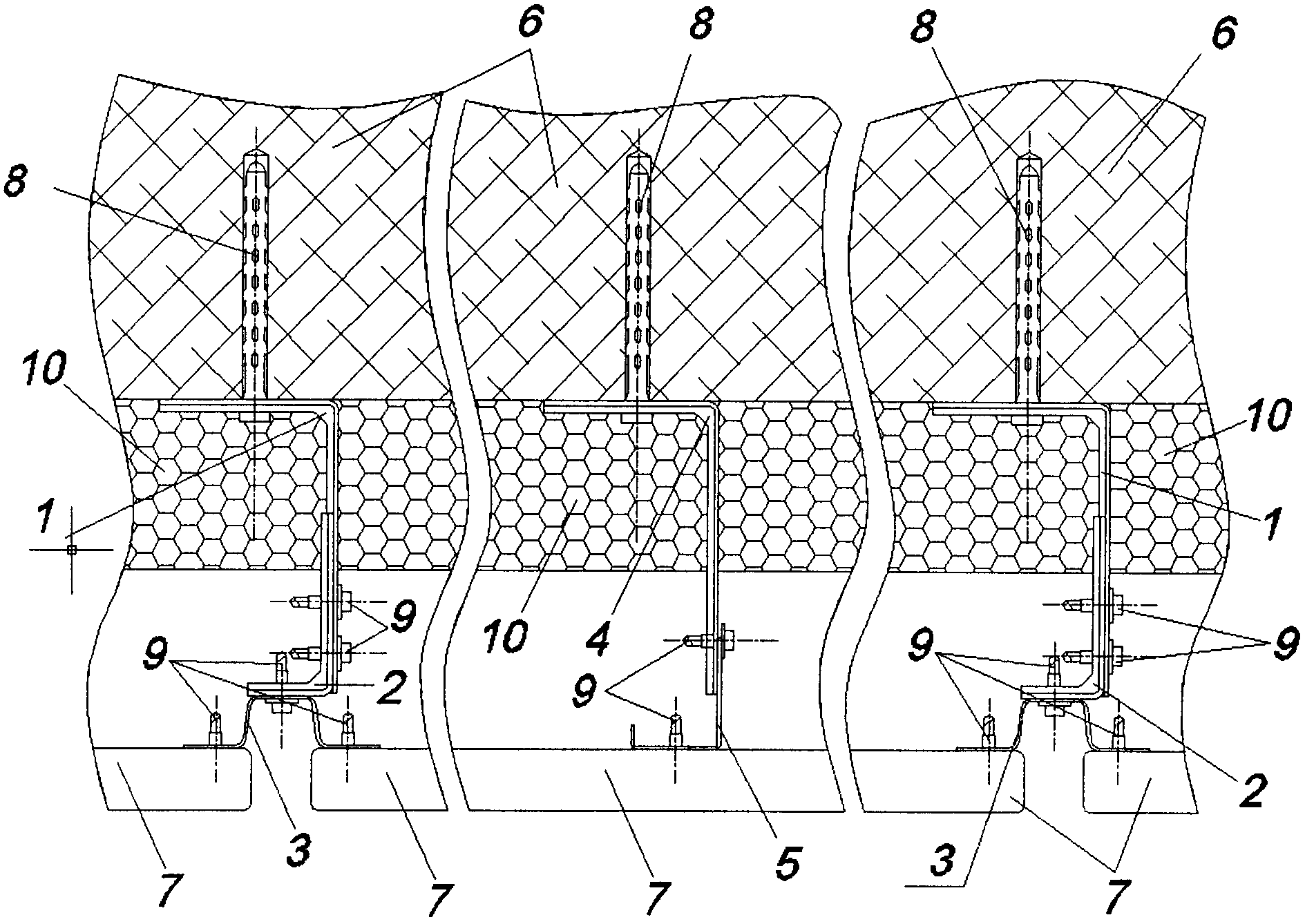
На фиг.2 показан горизонтальный разрез навесного вентилируемого фасада здания, выполненного с использованием заявляемых комплекта элементов для крепления облицовочных панелей и несущего каркаса навесного вентилируемого фасада здания, где 6 - стена здания, 7 облицовочная панель, 8 - дюбель с самонарезающим болтом, 9 - самонарезающий болт и 10 - утеплитель.Figure 2 shows a horizontal section of a hinged ventilated facade of the building, made using the inventive set of elements for attaching the facing panels and the supporting frame of the hinged ventilated facade of the building, where 6 is the wall of the building, 7 facing panel, 8 is a dowel with a self-tapping bolt, 9 is self-tapping a bolt and 10 - a heater.
Заявляемый комплект элементов для крепления облицовочных панелей выполнен из стали с антикоррозионным покрытием, например, алюмоцинковым, и подержит (см. фиг.1 и 2) несущие кронштейны, каждый из которых включает первую часть 1 несущего кронштейна и вторую часть 2 несущего кронштейна, выполненные Г-образными по форме. Первая часть 1 каждого несущего кронштейна выполнена с возможностью установки своей первой полкой на стене 6 здания с помощью анкеров (на фигурах не показаны) или дюбелей 8 с самонарезающими болтами, для чего в ее первой полке выполнены отверстия дли соединительного элемента. Первая часть 1 несущего кронштейна и вторая часть 2 несущего кронштейна выполнены с возможностью скрепления соответственно их второй и первой полками с использованием заклепок или болтов с гайками или самонарезающих болтов 9 и снабжены продольными ребрами жесткости. Вторая полка второй части 2 несущего кронштейна имеет длину 35-50 мм. Заявляемый комплект также содержит несущие направляющие 3 в виде протяженных П-образных профилей с отогнутыми наружу боковыми сторонами с образованием полок шириной 20-40 мм для установки облицовочных панелей 7, причем каждая несущая направляющая 3 выполнена с возможностью установки наружной поверхностью своей центральной полки на вторых полках вторых частей 2 несущих кронштейнов, для чего ширина ее центральной полки выбрана равной 20-35 мм. Кроме того, комплект содержит The inventive set of elements for attaching the facing panels is made of steel with an anticorrosive coating, for example, aluminum zinc, and will support (see Figs. 1 and 2) the supporting brackets, each of which includes the first part 1 of the supporting bracket and the second part 2 of the supporting bracket, made by -shaped in shape. The first part 1 of each supporting bracket is made with the possibility of installing its first shelf on the wall 6 of the building using anchors (not shown in the figures) or dowels 8 with self-tapping bolts, for which holes in the length of the connecting element are made in its first shelf. The first part 1 of the bearing bracket and the second part 2 of the bearing bracket are adapted to fasten their second and first shelves, respectively, using rivets or bolts with nuts or self-tapping bolts 9 and are provided with longitudinal stiffeners. The second shelf of the second part 2 of the bearing bracket has a length of 35-50 mm The inventive set also contains bearing rails 3 in the form of extended U-shaped profiles with outward curved sides to form shelves with a width of 20-40 mm for installation of cladding panels 7, and each carrier rail 3 is configured to install the outer surface of its Central shelf on the second shelves second parts 2 of the supporting brackets, for which the width of its central shelf is chosen equal to 20-35 mm. In addition, the kit contains
опорные кронштейны 4, которые выполнены Г-образными по форме с возможностью установки своими первыми полками на стене 6 здания с помощью анкеров (на фигурах не показаны) или дюбелей 8 самонарезающими болтами, для чего в их первых полках выполнены отверстия для соединительного элемента, а также опорные направляющие 5 в виде протяженных Г-образных профилей, выполненные с возможностью установки одной своей полкой на вторых полках опорных кронштейнов 4 с использованием заклепок или болтов с гайками или самонарезающих болтов 9. Первые части 1 несущих кронштейнов, вторые части 2 несущих кронштейнов и опорные кронштейны 4 выполнены из стали толщиной 1-3 мм, а несущие направляющие 3 и опорные направляющие 5 выполнены из стали толщиной 0,8-1,5 мм.supporting brackets 4, which are made L-shaped in shape with the possibility of installing their first shelves on the wall 6 of the building using anchors (not shown in the figures) or dowels 8 with self-tapping bolts, for which holes in the first shelves are made for the connecting element, and supporting guides 5 in the form of extended L-shaped profiles, made with the possibility of installing one of their own shelves on the second shelves of the supporting brackets 4 using rivets or bolts with nuts or self-tapping bolts 9. The first parts 1 carried Other brackets, the second parts 2 of the supporting brackets and the supporting brackets 4 are made of steel with a thickness of 1-3 mm, and the supporting guides 3 and the supporting guides 5 are made of steel with a thickness of 0.8-1.5 mm.
Заявляемый несущий каркас навесного вентилируемого фасада здания содержит (см. фиг.2) несущие кронштейны, каждый из которых включает первую часть 1 несущего кронштейна и вторую часть 2 несущего кронштейна, выполненные Г-образными по форме. Первая часть 1 каждого несущего кронштейна установлена своей первой полкой на стене 6 здания с помощью анкеров (на фигурах не показаны) или дюбелей 8 самонарезающими болтами, размещенных в выполненных в ее первой полке отверстиях для соединительного элемента. Первая часть 1 несущего кронштейна и вторая часть 2 несущего кронштейна снабжены продольными ребрами жесткости и скреплены соответственно их второй и первой полками с использованием заклепок или болтов с гайками или самонарезающих болтов 9. Заявляемый несущий каркас также содержит несущие направляющие 3 в виде протяженных П-образных профилей с отогнутыми наружу боковыми сторонами с образованием полок для установки облицовочных панелей 7, причем каждая несущая направляющая 3 установлена наружной поверхностью своей центральной полки на вторых полках вторых частей 2 несущих кронштейнов с использованием заклепок или болтов с гайками или самонарезающих болтов 9. Кроме того, несущий каркас содержит опорные кронштейны 4, которые выполнены Г-образными по форме и установлены своими первыми полками на стене 6 здания с помощью анкеров (на фигурах не показаны) или дюбелей 8 с самонарезающими болтами, размещенных в выполненных в их первой полке отверстиях для соединительного элемента, а также опорные направляющие 5 в виде протяженных Г-образных профилей, которые установлены одной своей полкой на вторых полках опорных кронштейнов 4 с использованием заклепок или болтов с гайками или самонарезающих болтов 9.The inventive supporting frame of the hinged ventilated facade of the building contains (see figure 2) bearing brackets, each of which includes the first part 1 of the bearing bracket and the second part 2 of the bearing bracket, made L-shaped in shape. The first part 1 of each supporting bracket is mounted with its first shelf on the wall 6 of the building using anchors (not shown in the figures) or dowels 8 with self-tapping bolts placed in the holes for the connecting element made in its first shelf. The first part 1 of the bearing bracket and the second part 2 of the bearing bracket are provided with longitudinal stiffeners and fastened respectively to their second and first shelves using rivets or bolts with nuts or self-tapping bolts 9. The inventive bearing frame also contains bearing guides 3 in the form of extended U-shaped profiles with the sides bent outward to form shelves for installing the cladding panels 7, with each supporting rail 3 mounted on the outer surface of its central shelf on the second shelves of the second parts 2 of the supporting brackets using rivets or bolts with nuts or self-tapping bolts 9. In addition, the supporting frame contains support brackets 4, which are made L-shaped in shape and installed by their first shelves on the wall 6 of the building using anchors (on not shown) or dowels 8 with self-tapping bolts located in the holes for the connecting element made in their first shelf, as well as supporting guides 5 in the form of extended L-shaped profiles, which are installed with one of their her shelf on the second shelves of the support brackets 4 using rivets or bolts with nuts or self-tapping bolts 9.
Монтаж заявляемого несущего каркаса навесного вентилируемого фасада здания осуществляют следующим образом.The installation of the inventive supporting frame of the hinged ventilated facade of the building is as follows.
Сначала осуществляют разметку стены 6 здания и устанавливают первые части 1 несущих кронштейнов и опорные кронштейны 4 на стене 6 здания с помощью анкеров (на фигурах не показаны) или дюбелей 8 с самонарезающими болтами. Закрепляют на стене First, mark the walls 6 of the building and install the first parts 1 of the supporting brackets and supporting brackets 4 on the wall 6 of the building using anchors (not shown in the figures) or dowels 8 with self-tapping bolts. Fasten to the wall
6 здания утеплитель 10 с использованием, например, дюбелей (на фигурах не показаны). Далее прикрепляют вторые части 2 несущих кронштейнов к первым частям 1 несущих кронштейнов с использованием заклепок или болтов с гайками или самонарезающих болтов 9 так, чтобы в дальнейшем обеспечить вертикальность расположения несущих направляющих 3 и опорных направляющих 5 и расположение их опорных поверхностей для установки облицовочных плит 7 в одной плоскости, а также создание необходимого воздушного зазора между утеплителем 10 и облицовочными плитами 7. Затем с использованием заклепок или болтов с гайками или самонарезающих болтов 9 устанавливают вертикально несущие направляющие 3 наружными поверхностями их центральных полок на вторых полках вторых частей 2 несущих кронштейнов, а также опорные направляющие 6 одной полкой на вторых полках опорных кронштейнов 4 так, чтобы обеспечить расположение опорных поверхностей для установки облицовочных плит 7 несущих направляющих 3 и опорных направляющих 5 в одной плоскости. В дальнейшем с помощью самонарезающих болтов 9 прикрепляют облицовочные плиты 7 к полкам несущих направляющих 3 с опорой облицовочных плит 7 на полки опорных направляющих 5. Облицовочные плиты 7 могут быть также прикреплены к полкам опорных направляющих 5 с помощью самонарезающих болтов 9. В результате этого несущие направляющие 3 совместно с первыми частями 1 несущих кронштейнов и вторыми частями 2 несущих кронштейнов будут воспринимать весовую нагрузку, создаваемую облицовочными плитами 7, и ветровое воздействие на них, а опорные направляющие 5 совместно с опорными кронштейнами 4 будут воспринимать только ветровое воздействие.6 building insulation 10 using, for example, dowels (not shown in the figures). Next, the second parts 2 of the supporting brackets are attached to the first parts 1 of the supporting brackets using rivets or bolts with nuts or self-tapping bolts 9 so as to further ensure the vertical arrangement of the supporting guides 3 and the supporting guides 5 and the arrangement of their supporting surfaces for installing the facing plates 7 in one plane, as well as creating the necessary air gap between the heater 10 and the facing plates 7. Then, using rivets or bolts with nuts or self-tapping bolts 9, vertical supporting rails 3 are installed by the outer surfaces of their central shelves on the second shelves of the second parts 2 of the supporting brackets, as well as supporting rails 6 by one shelf on the second shelves of the supporting brackets 4 so as to provide an arrangement of the supporting surfaces for installing the facing plates 7 of the supporting rails 3 and the supporting guides 5 in one plane. Subsequently, with the help of self-tapping bolts 9, the facing plates 7 are attached to the shelves of the bearing guides 3 with the support of the facing plates 7 on the shelves of the supporting guides 5. The facing plates 7 can also be attached to the shelves of the supporting guides 5 using self-cutting bolts 9. As a result, the bearing guides 3 together with the first parts 1 of the supporting brackets and the second parts 2 of the supporting brackets will perceive the weight load created by the cladding plates 7 and the wind effect on them, and the bearing guide The shrouds 5 together with the supporting brackets 4 will only perceive the wind effect.
Таким образом, полезная модель обеспечивает снижение стоимости несущего каркаса навесного вентилируемого фасада здания и комплекта его элементов, а также упрощение монтажа.Thus, the utility model reduces the cost of the supporting frame of the hinged ventilated facade of the building and a set of its elements, as well as simplifying installation.
Claims (14)
Priority Applications (1)
| Application Number | Priority Date | Filing Date | Title |
|---|---|---|---|
| RU2008134457/22U RU79910U1 (en) | 2008-08-18 | 2008-08-18 | SET OF ELEMENTS FOR FIXING FACING PANELS AND A CARRYING FRAME OF A HINGED VENTED FACADE OF A BUILDING ON ITS BASIS |
Applications Claiming Priority (1)
| Application Number | Priority Date | Filing Date | Title |
|---|---|---|---|
| RU2008134457/22U RU79910U1 (en) | 2008-08-18 | 2008-08-18 | SET OF ELEMENTS FOR FIXING FACING PANELS AND A CARRYING FRAME OF A HINGED VENTED FACADE OF A BUILDING ON ITS BASIS |
Publications (1)
| Publication Number | Publication Date |
|---|---|
| RU79910U1 true RU79910U1 (en) | 2009-01-20 |
Family
ID=40376411
Family Applications (1)
| Application Number | Title | Priority Date | Filing Date |
|---|---|---|---|
| RU2008134457/22U RU79910U1 (en) | 2008-08-18 | 2008-08-18 | SET OF ELEMENTS FOR FIXING FACING PANELS AND A CARRYING FRAME OF A HINGED VENTED FACADE OF A BUILDING ON ITS BASIS |
Country Status (1)
| Country | Link |
|---|---|
| RU (1) | RU79910U1 (en) |
Cited By (2)
| Publication number | Priority date | Publication date | Assignee | Title |
|---|---|---|---|---|
| RU2545584C2 (en) * | 2010-01-25 | 2015-04-10 | Оликон Аб | Mounting profile to suspend tiles on external wall |
| RU2812869C2 (en) * | 2022-06-15 | 2024-02-05 | Хильти Акциенгезельшафт | Device, system and method for installing hinged ventilated facade |
-
2008
- 2008-08-18 RU RU2008134457/22U patent/RU79910U1/en not_active IP Right Cessation
Cited By (2)
| Publication number | Priority date | Publication date | Assignee | Title |
|---|---|---|---|---|
| RU2545584C2 (en) * | 2010-01-25 | 2015-04-10 | Оликон Аб | Mounting profile to suspend tiles on external wall |
| RU2812869C2 (en) * | 2022-06-15 | 2024-02-05 | Хильти Акциенгезельшафт | Device, system and method for installing hinged ventilated facade |
Similar Documents
| Publication | Publication Date | Title |
|---|---|---|
| RU93845U1 (en) | BRACKET FOR FASTENING THE HINGED PANEL OF THE BUILDING COVERING AND COMPONENT PARTS OF THE BRACKET | |
| WO2014142776A1 (en) | Load-bearing framework for a suspended facade of a building | |
| RU124284U1 (en) | FASTENING SYSTEM FOR FACING PANELS OF MOUNTED VENTILATED FACADES (BRACKET, EXTENSION INSERT) | |
| RU92063U1 (en) | FIXING SYSTEM FOR FACING PANELS OF MOUNTED VENTILATED FACADES, VERTICAL PROFILE, HORIZONTAL END PROFILE, HORIZONTAL ROW PROFILE, CORNER SHELF, CORNER PROFILE | |
| RU79910U1 (en) | SET OF ELEMENTS FOR FIXING FACING PANELS AND A CARRYING FRAME OF A HINGED VENTED FACADE OF A BUILDING ON ITS BASIS | |
| RU89552U1 (en) | KLAMMER AND THE CARRIER FOR ITS FASTENING | |
| RU40066U1 (en) | BRACKET FOR FASTENING THE HINGED PANEL OF THE BUILDING FACING | |
| RU110786U1 (en) | MOUNTED FACADE FASTENING SYSTEM | |
| US20140090326A1 (en) | Aesthetic wall facade systems, devices, and methods | |
| RU48193U1 (en) | SIAL VENTILATED FACADES SYSTEM (OPTIONS) | |
| RU124916U1 (en) | ASSEMBLY BRACKET FOR FRONT SYSTEM | |
| RU67129U1 (en) | PROFILE SYSTEM FOR THE MODULAR FRAME OF THE HINGED VENTILATED FACADE OF THE BUILDING | |
| RU114471U1 (en) | VENTILATED FACADE BUILDING FACADE SYSTEM (OPTIONS) | |
| RU186046U1 (en) | DESIGN OF THE MODULE OF HINGED FACING PANELS | |
| RU67141U1 (en) | SYSTEM OF FASTENING OF THE FACING PANELS OF THE CASSETTE TYPE | |
| RU88373U1 (en) | FIXING SYSTEM FOR FACING PANELS OF MOUNTED VENTILATED FACADES (OPTIONS), BRACKET, VERTICAL GUIDE PROFILE, SLIDING (OPTIONS), DRAINAGE DRAIN | |
| RU80480U1 (en) | BRACKET FOR FASTING FACING OR FLOORING | |
| RU137884U1 (en) | BRACKET FOR FIXING HINGED FACADE STRUCTURE | |
| RU2005125910A (en) | METHOD OF INSTALLATION OF VENTED FACING OF BUILDINGS AND DESIGN OF FENCING FOR IMPLEMENTATION OF THE METHOD | |
| RU60562U1 (en) | SYSTEM OF PROFILES FOR MODULAR FRAME OF MOUNTED VENTILATED FACADE OF BUILDINGS (OPTIONS), PROFILE OF BEARING AND SUPPORT BRACKETS, PROFILE OF VERTICAL GUIDE, PROFILE OF GUIDE SALES OF SALES | |
| RU70525U1 (en) | VENTILATED FACADE BUILDING FACADE SYSTEM (OPTIONS) | |
| RU55396U1 (en) | BEARING PROFILE OF HINGED FACADE | |
| RU218899U1 (en) | BRACKET FOR FASTENING PROFILES OF SUSPENDED FACADE SYSTEMS | |
| RU96888U1 (en) | BRACKET FOR MOUNTED FACADE SYSTEM WITH AIR GAP (OPTIONS) | |
| RU26061U1 (en) | BUILDING HOUSING FACADE FRAME BUILDING |
Legal Events
| Date | Code | Title | Description |
|---|---|---|---|
| MM1K | Utility model has become invalid (non-payment of fees) |
Effective date: 20090819 |