RU69089U1 - RECYCLING HYDRO POWER PLANT - Google Patents
RECYCLING HYDRO POWER PLANT Download PDFInfo
- Publication number
- RU69089U1 RU69089U1 RU2007106547/22U RU2007106547U RU69089U1 RU 69089 U1 RU69089 U1 RU 69089U1 RU 2007106547/22 U RU2007106547/22 U RU 2007106547/22U RU 2007106547 U RU2007106547 U RU 2007106547U RU 69089 U1 RU69089 U1 RU 69089U1
- Authority
- RU
- Russia
- Prior art keywords
- water
- discharge pipe
- pipe
- shutter
- turbine
- Prior art date
Links
Classifications
-
- Y—GENERAL TAGGING OF NEW TECHNOLOGICAL DEVELOPMENTS; GENERAL TAGGING OF CROSS-SECTIONAL TECHNOLOGIES SPANNING OVER SEVERAL SECTIONS OF THE IPC; TECHNICAL SUBJECTS COVERED BY FORMER USPC CROSS-REFERENCE ART COLLECTIONS [XRACs] AND DIGESTS
- Y02—TECHNOLOGIES OR APPLICATIONS FOR MITIGATION OR ADAPTATION AGAINST CLIMATE CHANGE
- Y02E—REDUCTION OF GREENHOUSE GAS [GHG] EMISSIONS, RELATED TO ENERGY GENERATION, TRANSMISSION OR DISTRIBUTION
- Y02E10/00—Energy generation through renewable energy sources
- Y02E10/20—Hydro energy
Abstract
Утилизационная гидроэлектростанция предназначена для выработки электроэнергии при сбросе очищенных сточных вод в естественные водоемы и может быть использована для выработки электроэнергии при подаче питьевой воды в город с избыточным напором из расположенного выше водохранилища. Подающий в гидравлическую турбину (1), сочлененную с электрогенератором (2), воду напорный трубопровод (3) и отводящий воду трубопровод (7) врезаны в нижнюю часть трубопровода (12) выпуска очищенных сточных вод. На трубопроводе (12) между врезками установлен затвор (13) и сальниковый компенсатор (14). На подающем воду напорном трубопроводе (3) установлены предтурбинный затвор (4) и сальниковый компенсатор (5). Отводящий трубопровод (7) также оборудован сальниковым компенсатором (8). Выработанная электроэнергия через распредустройство (10) подается в линию электропередачи (11). 2 ил.A recycling hydroelectric power station is designed to generate electricity by discharging treated wastewater into natural water bodies and can be used to generate electricity by supplying drinking water to a city with excessive pressure from a reservoir located above. The pressure pipeline (3), which is connected to a hydraulic turbine (1) coupled with an electric generator (2), and the water discharge pipe (7) are cut into the lower part of the treated sewage discharge pipe (12). On the pipeline (12) between the insets a shutter (13) and an stuffing box compensator (14) are installed. A pre-turbine shutter (4) and a stuffing box compensator (5) are installed on the water supply pressure pipe (3). The discharge pipe (7) is also equipped with an expansion joint (8). The generated electricity through the switchgear (10) is supplied to the power line (11). 2 ill.
Description
Полезная модель относится к области электроэнергетики и может быть использована для выработки электроэнергии при сбросе очищенных сточных вод в естественные водоемы.The utility model relates to the field of electricity and can be used to generate electricity when discharged treated wastewater into natural water bodies.
Известно устройство гидроэлектростанции (ГЭС) включающее плотину, создающую перепад уровней воды в естественном водоеме; каналы, подводящий воду к гидравлической турбине и отводящий от нее воду в нижний бьеф; гидравлическую турбину, соединенную с электрогенератором; здание, в котором устанавливаются гидравлическая турбина с электрогенератором, может быть встроенным в плотину или находится на каком-либо расстоянии от плотины (см. Баптиданов Л.Н., Тарасов В.И. Электрические станции и подстанции. Издание 2 переработанное - М: Энергия, 1969. 424 с.).A device for a hydroelectric power station (HPP) is known, including a dam creating a difference in water levels in a natural body of water; channels leading water to the hydraulic turbine and diverting water from it to the downstream; a hydraulic turbine connected to an electric generator; a building in which a hydraulic turbine with an electric generator is installed can be built into the dam or located at some distance from the dam (see Baptidanov L.N., Tarasov V.I. Power plants and substations. Edition 2 revised - M: Energy , 1969.442 s.).
Наиболее дорогим и сложным элементом гидроэлектростанции является плотина, кроме того, при создании перепада уровней воды образуется водохранилище, которое затапливает обширные площади и создает впоследствии неблагоприятные экологические последствия.The most expensive and complex element of a hydroelectric power station is a dam, in addition, when creating a difference in water levels, a reservoir forms that floods vast areas and subsequently creates adverse environmental consequences.
Наиболее близким устройством того же назначения к заявленной полезной модели по совокупности признаков является устройство деривационной гидроэлектростанции, включающее плотину, подводящий воду напорный трубопровод, гидравлическую турбину, соединенную с электрогенератором, отводящий воду в нижний бьеф трубопровод (см. Баптиданов Л.Н., Тарасов В.И. Электрические станции и подстанции. Издание 2 переработанное - М: Энергия, 1969. 424 с.) и принятое за прототип. К причинам, препятствующим достижению указанного ниже технического результата при использовании известного устройства, принятого за прототип, относится то, что в известном устройстве имеется The closest device of the same purpose to the claimed utility model in terms of all the features is the device of a derivative hydroelectric power station, including a dam, a water supply pressure pipe, a hydraulic turbine connected to an electric generator, water drainage to the downstream pipe (see Baptidanov L.N., Tarasov V .I. Power plants and substations. Edition 2 revised - M: Energy, 1969. 424 pp.) And adopted as a prototype. For reasons that impede the achievement of the following technical result when using the known device adopted for the prototype, is that the known device has
плотина, которая находится выше расположения электростанции и является дорогостоящим и сложным элементом деривационной гидроэлектростанции; не удается полностью исключить создания водохранилища в верхнем бьефе; необходимость строительства трубопровода деривации; необходимость регулирования уровня в водохранилище.a dam, which is located above the location of the power plant and is an expensive and complex element of a derivative hydroelectric power station; it is not possible to completely exclude the creation of a reservoir in the upper pool; the need to build a derivation pipeline; the need to regulate the level in the reservoir.
Сущность полезной модели заключается в следующем:The essence of the utility model is as follows:
После очистки канализационных стоков на очистных сооружениях канализации они по системе трубопроводов сбрасываются в естественные водоемы. Во многих случаях водоемы расположены гораздо ниже очистных сооружений. Разница между уровнем расположения очистных сооружений и уровнем поверхности воды в естественном водоеме может достигать нескольких десятков метров. Утилизационная гидроэлектростанция располагается вблизи трубопроводов выпуска очищенных сточных вод. Объем стоков крупных городов измеряется единицами или десятками кубических метров в секунду. Следовательно, сбрасываемые в естественные водоемы стоки обладают достаточно большой кинетической энергией, мощность которой определяется известным выражениемAfter the treatment of sewage in sewage treatment plants, they are discharged through a pipeline system into natural water bodies. In many cases, water bodies are located much lower than treatment facilities. The difference between the level of the location of treatment facilities and the level of the surface of the water in a natural body of water can reach several tens of meters. Recycling hydroelectric power station is located near the pipelines for the release of treated waste water. The volume of runoff in large cities is measured in units or tens of cubic meters per second. Therefore, the effluents discharged into natural water bodies have a sufficiently large kinetic energy, the power of which is determined by the well-known expression
N=ρ·Q·H·g·10-3 кBт,N = ρ · Q · H · g · 10 -3 kBt,
где: ρ - плотность жидкости в кг/м3, Q - объем стоков в м3/с, Н - разность уровней в м, g - ускорение свободного падения в м/с2.where: ρ is the fluid density in kg / m 3 , Q is the volume of effluents in m 3 / s, N is the difference in levels in m, g is the acceleration of gravity in m / s 2 .
Эта энергия полезно не используется.This energy is not useful.
Технический результат - получение электрической энергии при использовании кинетической энергии сбрасываемых в естественный водоем очищенных канализационных стоков с меньшими издержками.EFFECT: obtaining electric energy by using the kinetic energy of treated sewage discharged into a natural body of water with lower costs.
Указанный технический результат при осуществлении полезной модели достигается тем, что в известном устройстве, включающем плотину, подводящий воду напорный трубопровод, гидравлическую турбину, соединенную с электрогенератором и отводящий воду трубопровод, подводящий воду напорный трубопровод проложен от расположенной выше плотины до места установки турбины, а по отводящему трубопроводу The specified technical result in the implementation of the utility model is achieved by the fact that in the known device including a dam, a water supply pressure pipe, a hydraulic turbine connected to an electric generator and a water discharge pipe, a water supply pipe is laid from the dam located above to the installation site of the turbine, and outlet pipe
отработавшая в турбине вода отводится в нижний бьеф. Особенность заключается в том, что подводящий воду напорный трубопровод и отводящий воду трубопровод врезаются в трубопровод выпуска очищенных сточных вод, на который между врезками установлен затвор. Вода в турбину подается по подводящему напорному трубопроводу. Подводящий воду напорный трубопровод оборудуется предтурбинным затвором и сальниковым компенсатором для предотвращения линейных деформаций водовода. Трубопровод выпуска очищенных сточных вод также оборудуется сальниковым компенсатором. Отработавшая вода от турбины отводится в сбросной колодец, из которого по отводящему воду трубопроводу соответствующего сечения, оборудованному сальниковым компенсатором, отводится в трубопровод выпуска за установленным на нем затвором ниже уровня сбросного колодца.waste water in the turbine is discharged to the downstream. The peculiarity lies in the fact that the water supply pressure pipe and the water discharge pipe cut into the sewage discharge pipe, on which a shutter is installed between the insets. Water is supplied to the turbine through the inlet pressure pipe. The pressure water supply line is equipped with a pre-turbine valve and an expansion joint to prevent linear deformation of the water conduit. The sewage discharge pipe is also equipped with an expansion joint. Exhaust water from the turbine is discharged to a discharge well, from which a drainage pipe of the corresponding section equipped with an expansion joint is diverted to the discharge pipe behind a valve installed on it below the level of the discharge well.
В целях обеспечения нормальных условий эксплуатации электрического и гидравлического оборудования оборудование гидроэлектростанции размещается в здании ГЭС, которое может быть сооружено из облегченных сборных конструкций.In order to ensure normal operating conditions for electric and hydraulic equipment, the equipment of the hydroelectric power station is located in the building of the hydroelectric power station, which can be constructed from lightweight prefabricated structures.
Электростанция оборудуется устройствами защиты и автоматики, позволяющими работать в полностью автоматическом режиме, и устройством выдачи электрической мощности в электрическую сеть или передачи ее выделенному потребителю.The power plant is equipped with protection and automation devices, allowing to work in fully automatic mode, and a device for delivering electric power to the electric network or transmitting it to a dedicated consumer.
Кроме того, особенность полезной модели заключается в том, что ее можно использовать для выработки электроэнергии при подаче питьевой воды в город в случае если его водоснабжение осуществляется с избыточным напором из выше расположенного водохранилища.In addition, a feature of the utility model is that it can be used to generate electricity when drinking water is supplied to the city if it is supplied with excess pressure from a reservoir located above.
На чертежах представлено:The drawings show:
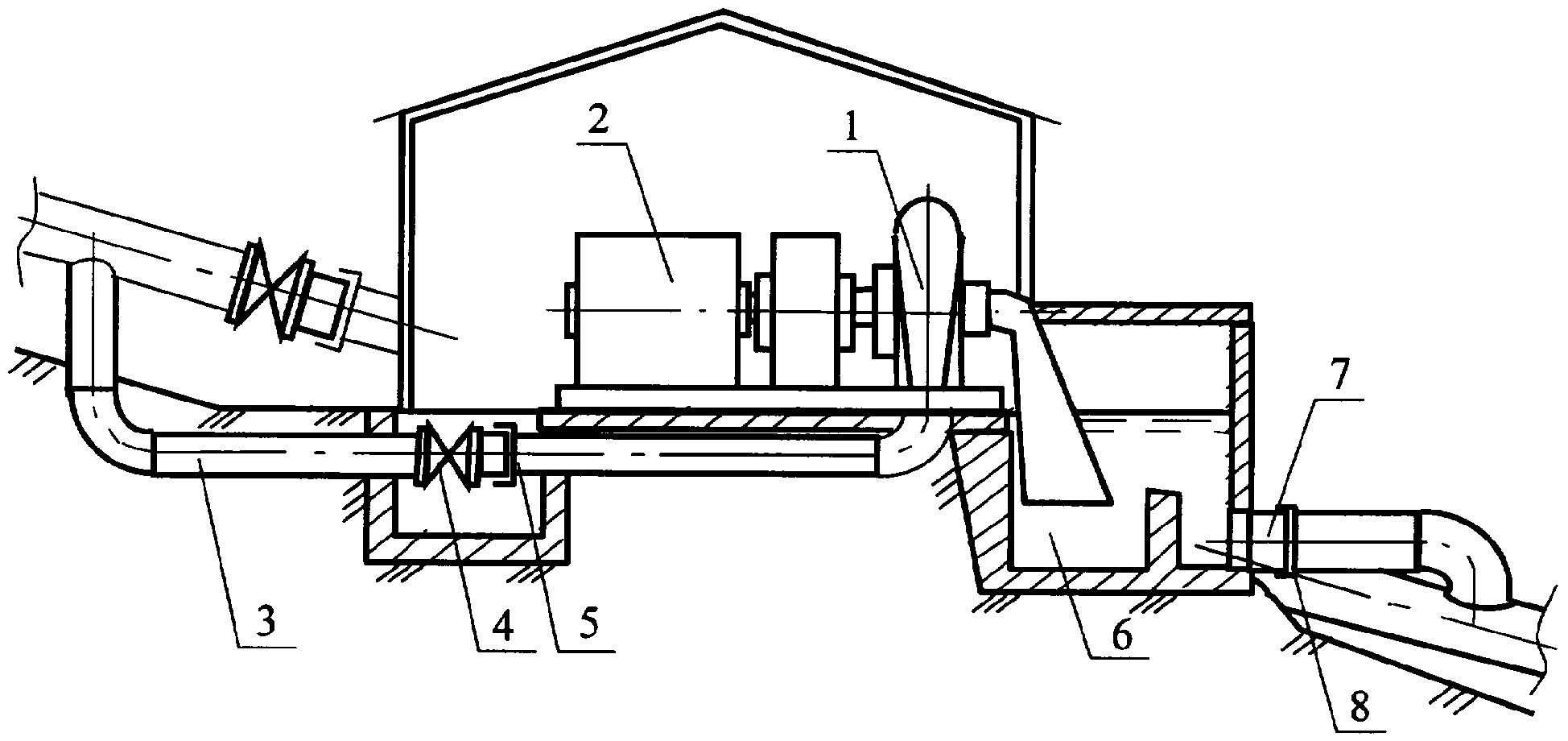
На фиг.1 изображен разрез 1-1 станционного узла.Figure 1 shows a section 1-1 of the station node.
На фиг.2 изображен план компоновки станционного узла.Figure 2 shows the layout of the station node.
Сведения, подтверждающие возможность осуществления полезной модели с получением вышеуказанного технического результата, заключаются в следующем.Information confirming the feasibility of implementing the utility model with obtaining the above technical result is as follows.
Полезная модель содержит гидроагрегат, состоящий из гидравлической турбины 1, сочлененной с электрогенератором 2; подводящий воду напорный трубопровод 3; предтурбинный затвор 4; сальниковый компенсатор 5; сбросной колодец 6; отводящий воду трубопровод 7 с сальниковым компенсатором 8; здание 9 электростанции; устройство 10 выдачи мощности; линию электропередачи 11. Подводящий воду напорный трубопровод 3 и отводящий воду трубопровод 7 врезаны в нижнюю часть трубопровода 12 выпуска очищенных сточных вод, на который между врезками установлены затвор 13 и сальниковый компенсатор 14.The utility model contains a hydraulic unit consisting of a hydraulic turbine 1 coupled to an electric generator 2; water supply pressure pipe 3; pre-turbine shutter 4; stuffing box compensator 5; discharge well 6; water discharge pipe 7 with stuffing box compensator 8; building 9 power plants; power output device 10; power line 11. The water supply pressure pipe 3 and the water discharge pipe 7 are cut into the lower part of the treated sewage discharge pipe 12, onto which a shutter 13 and an stuffing box 14 are installed between the insets.
Работа устройства осуществляется следующим образом. Открывается предтурбинный затвор 4 и закрывается затвор 13, установленный на трубопроводе 12 выпуска очищенных сточных вод. Сбрасываемая вода при этом проходит через гидравлическую турбину 1 и приводит в движение турбину с электрогенератором 2, который вырабатывает электроэнергию. Отработавшая вода от гидравлической турбины 1 отводится в сбросной колодец 6, из которого по отводящему воду трубопроводу 7 отводится в трубопровод 12 выпуска за установленным на нем затвором 13 ниже уровня сбросного колодца 6. Выработанная электрогенератором 2 электроэнергия через устройство 10 выдачи мощности подается в линию электропередачи 11.The operation of the device is as follows. The pre-turbine shutter 4 opens and the shutter 13 is installed, installed on the pipeline 12 for the release of treated wastewater. In this case, the discharged water passes through a hydraulic turbine 1 and drives a turbine with an electric generator 2, which generates electricity. The waste water from the hydraulic turbine 1 is discharged into a discharge well 6, from which through a water discharge pipe 7 it is discharged into the exhaust pipe 12 behind the shutter 13 installed thereon below the level of the discharge well 6. The electricity generated by the electric generator 2 is supplied through the power output device 10 to the power transmission line 11 .
В здании 9 ГЭС размещаются устройства автоматического управления гидроагрегатом, возбуждения, панель собственных нужд и другие вспомогательные устройства.The building 9 of the hydroelectric station houses devices for automatic control of the hydraulic unit, excitation, auxiliary panel and other auxiliary devices.
Claims (1)
Priority Applications (1)
| Application Number | Priority Date | Filing Date | Title |
|---|---|---|---|
| RU2007106547/22U RU69089U1 (en) | 2007-02-20 | 2007-02-20 | RECYCLING HYDRO POWER PLANT |
Applications Claiming Priority (1)
| Application Number | Priority Date | Filing Date | Title |
|---|---|---|---|
| RU2007106547/22U RU69089U1 (en) | 2007-02-20 | 2007-02-20 | RECYCLING HYDRO POWER PLANT |
Publications (1)
| Publication Number | Publication Date |
|---|---|
| RU69089U1 true RU69089U1 (en) | 2007-12-10 |
Family
ID=38904283
Family Applications (1)
| Application Number | Title | Priority Date | Filing Date |
|---|---|---|---|
| RU2007106547/22U RU69089U1 (en) | 2007-02-20 | 2007-02-20 | RECYCLING HYDRO POWER PLANT |
Country Status (1)
| Country | Link |
|---|---|
| RU (1) | RU69089U1 (en) |
-
2007
- 2007-02-20 RU RU2007106547/22U patent/RU69089U1/en not_active IP Right Cessation
Similar Documents
| Publication | Publication Date | Title |
|---|---|---|
| US6396162B1 (en) | Underground hydroelectric plant | |
| US7501712B2 (en) | Process for using waste water from community sewer systems to generate electrical power | |
| US8231327B2 (en) | River high pressure energy conversion machine | |
| EP2279344B1 (en) | Electricity generating arrangement | |
| JP2017210960A (en) | Hydraulic power generation facility | |
| US20140265328A1 (en) | Electricity generating arrangement | |
| CN103352452B (en) | Flexible double-tube water diversion, electricity generation and water storage integrated device suitable for rivulets in mountainous areas | |
| WO2012177182A1 (en) | Diversion hydropower plant cascade | |
| AU2009284018B2 (en) | Hydroelectric power generation system | |
| KR20110055355A (en) | Pro-environment-like small hydroelectric system and method | |
| RU2629350C1 (en) | Hydrostorage system | |
| KR20060120873A (en) | Hydraulic power generator system | |
| JP2013024161A (en) | Intra-building water power generation system utilizing fall energy of high-rise building sewage | |
| RU69089U1 (en) | RECYCLING HYDRO POWER PLANT | |
| KR100642333B1 (en) | The hydroelectric power generation apparatus using to smallhydraulic power | |
| CN208456765U (en) | A kind of artesian water power generator | |
| CN108798967A (en) | A kind of artesian water electricity-generating method | |
| Ioan et al. | approach channel modelling with advanced hydroinformatic tool, case study: small hydro power plant Huta Certeze, Romania | |
| JP4597257B1 (en) | Hydroelectric power generation system | |
| RU2002888C1 (en) | Pressure derivation cascade for hydro-electric power station | |
| CN219011141U (en) | Dual-power tunnel hydroelectric generation structure in water-rich area | |
| WO2020235842A1 (en) | Building-type pumped storage power generation system | |
| WO2011066676A1 (en) | A multi-stage power generating apparatus utilizing flow of water | |
| RU33131U1 (en) | Damless hydroelectric power station | |
| Devlin et al. | SCOP: The SCOP of Things to Come; Innovative Project Delivery Method Sets the Stage for Success |
Legal Events
| Date | Code | Title | Description |
|---|---|---|---|
| MM1K | Utility model has become invalid (non-payment of fees) |
Effective date: 20080221 |