RU6155U1 - END CAMERA LOCK FOR LAUNCHING AND RECEIVING FLOW APPLIANCES WHEN OPERATING PIPELINES - Google Patents
END CAMERA LOCK FOR LAUNCHING AND RECEIVING FLOW APPLIANCES WHEN OPERATING PIPELINES Download PDFInfo
- Publication number
- RU6155U1 RU6155U1 RU97104949/20U RU97104949U RU6155U1 RU 6155 U1 RU6155 U1 RU 6155U1 RU 97104949/20 U RU97104949/20 U RU 97104949/20U RU 97104949 U RU97104949 U RU 97104949U RU 6155 U1 RU6155 U1 RU 6155U1
- Authority
- RU
- Russia
- Prior art keywords
- shutter
- lid
- working position
- hoops
- launching
- Prior art date
Links
Abstract
Концевой затвор камер для запуска и приема поточных снарядов при эксплуатации трубопроводов, содержащий герметично закрепленный соосно камере на ее свободном конце корпус затвора с подвижно закрепленной на нем откидной крышкой и замковым узлом фиксации крышки в рабочем положении, отличающийся тем, что откидная крышка закреплена на поворотном механизме с возможностью ее отвода из прикамерной зоны запасовки или приема поточных снарядов, причем узел фиксации крышки в рабочем положении выполнен в виде подвижных фиксаторов с механизмами их привода в виде кинематически связанных со смежными концами фиксаторов двумя винтовыми механизмами, диаметрально противоположно расположенными на корпусе затвора, при этом фиксаторы выполнены в виде по крайней мере двух подвижных полуобручей с профилированной замковой поверхностью, образующей в рабочем положении охватывающий корпус затвора замок с оппозитными замковым поверхностям полуобручей замковыми поверхностями, выполненными в виде кольцевых буртиков, соответственно на свободной торцевой части корпуса затвора и по наружному периметру крышки.The end shutter of the chambers for launching and receiving in-line projectiles during operation of pipelines, comprising a shutter body hermetically sealed coaxially to the chamber at its free end, with a hinged lid movably fixed thereto and a lid lock fixing unit in the operating position, characterized in that the hinged lid is mounted on a rotary mechanism with the possibility of its removal from the near-storage zone of storage or reception of continuous shells, and the lid fixing unit in the working position is made in the form of movable clips with mechanisms x actuators in the form of kinematically connected with adjacent ends of the latches by two screw mechanisms diametrically oppositely located on the shutter body, while the latches are made in the form of at least two movable semi-hoops with a profiled locking surface, forming in the working position a lock enclosing the shutter housing with opposed locking surfaces semi-hoops with locking surfaces made in the form of annular beads, respectively, on the free end part of the shutter body and on the outer at the perimeter of the cap.
Description
Концевой затвор камер для запуска и приема побочных снарядов при эксплуатации трубопроводов. Полезная модель относится к технике эксплуатации магистральных трубопроводов и может быть использована в газовой и нефтяной промышленности для запуска в трубопровод и извлечения из него средств дефектоскопии, очистных элементов и других поточных снарядов. Из уровня техники известно большое количество устройств для запуска и приема поточных снарядов применяемых при после монтажа и при эксплуатации трубопроводов, см, например, патент Р.Ф. № 2043175, 1992г.; А.С. СССР, № 1683831, 1989г.; А.С.СССР № 1694255, 1989г., пат. США №2028778,1936г.; А.С.СССР №1158257 и т.д. Все вышеуказанные устройства содержат в своем составе камеры запуска и камеры приема поточных снарядов, которые на свободных концах оборудуются концевыми затворами. Эти затворы открывают и закрывают при установке поточных снарядов в камере перед их зап ском в трубопровод или приемом по окончанию работ. Основным недостатком этих камер является ненадежная конструкция замков и механизма поворота крышки концевого затвора . В связи со значительными диаметрами современных трубопроводов для перекачки, например, нефтепродуктов, крышка концевого затвора имеет значительную массу, при этом она должна быть плотно без перекосов притянута к корпусу камеры и в тоже время легко и быстро открываться. В известных конструкциях шарнирное соединенне крышки затвора с камерой и фиксируюпще крышку замки имеют ненадежную констр 1шию, что не исключает возможность самопроизвольного раскрытия затвора под давлением. Это приводит к возникновению аварийных ситуаций и снижает безопасность работ. М.кл. В 08 В 9/00 Полезная модель.The end shutter of the chambers for launching and receiving side projectiles during the operation of pipelines. The utility model relates to the operation technology of main pipelines and can be used in the gas and oil industry to launch into the pipeline and extract from it flaw detection tools, treatment elements and other flow projectiles. The prior art there are a large number of devices for launching and receiving in-line projectiles used after installation and operation of pipelines, see, for example, patent RF No. 2043175, 1992; A.S. USSR, No. 1683831, 1989; A.S. USSR, No. 1694255, 1989, Pat. US No. 2028778.1936; A.S.SSSR No. 1158257, etc. All of the above devices contain launch chambers and cameras for receiving continuous-flow projectiles, which are equipped with end locks at the free ends. These valves open and close when installing in-line projectiles in the chamber before they are introduced into the pipeline or received at the end of work. The main disadvantage of these cameras is the unreliable design of the locks and the mechanism for turning the end shutter lid. Due to the significant diameters of modern pipelines for pumping, for example, petroleum products, the end shutter cover has a considerable mass, while it must be tightly drawn to the camera body without distortions and at the same time it can be easily and quickly opened. In the known constructions, the hinged connection of the shutter lid to the camera and the locking latch of the locks have an unreliable design, which does not exclude the possibility of spontaneous opening of the shutter under pressure. This leads to emergencies and reduces the safety of work. M.cl. 08 V 9/00 Utility model.
Известна также камера для приема и запуска поточных снарядов по А.С.СССР №867438, 1979г., которая содержит корпус, свободный конец которого оборудован концевым затвором, выполненным в виде аксиально расположенных цилиндров с системой ввода поточных снарядов и механизмом поворота наружного цилиндра. Известная камера, хотя и позволяет повысить безопасность работы и частично автоматизировэтъ процесс ее работы, но характеризуется высокой сложностью в изготовлении и малой экспл атационной надежностью и в настоящее время не применяется.Also known is a chamber for receiving and launching continuous-flow projectiles according to A.S. USSR, No. 867438, 1979, which contains a housing, the free end of which is equipped with an end shutter made in the form of axially arranged cylinders with an input system for continuous-flow shells and an outer cylinder rotation mechanism. The well-known camera, although it can improve the safety of work and partially automate the process of its operation, is characterized by high complexity in manufacturing and low operational reliability and is not currently used.
За прототрш полезной модели выбрано устройство по патенту Р.Ф. №2043175, 1992г., в конструкции которого используется концевой затвор с шарнирно подвешенной крышкой и замковым устройством фиксации крышки в рабочем положении. В конструкции этого концевого затвора не предусмотрено никаких средств механизации закрытия и открытия крышки затвора, а также ее отвода из зоны запасовки и приема поточных снарядов. Эта конструкция хотя и проста в изготовлении, но характеризуется ненадежностью и повышенной опасность при эксплуатации из-за возможности самопроизвольного открытия; очень неудобна в работе, поскольку движение крышки при открытии или закрыты i происходит в вертикальной плоскости, что потенциально может привести к тяжелому травматизму работаюшдх.For prototrush utility model selected device according to the patent of R.F. No. 2043175, 1992, in the construction of which an end closure with a hinged lid and a locking device for fixing the lid in the working position is used. The design of this end shutter does not provide any means of mechanizing the closing and opening of the shutter lid, as well as its removal from the storage area and the reception of continuous projectiles. This design, although simple to manufacture, is characterized by unreliability and increased danger during operation due to the possibility of spontaneous opening; it is very inconvenient to work, because the movement of the lid when opening or closed i occurs in a vertical plane, which can potentially lead to serious personal injury.
Технической задачей, решаемой.. . i .- является повышение, безопасности и надежности эксплуатации устройства.The technical problem to be solved ... i .- is the enhancement, safety and reliability of the operation of the device.
Решение поставленной задачи обеспечивается тем, что в концевом затворе камер Д.11Я запуска и приема поточных снарядов при эксплуатации трубопроводов содержапщм герметично закрепленный соосно камере на ее свободном конце корпус затвора с подвижно закрепленной на нем откидной крышкой и замковым узлом фиксации крышки в рабочем положешш, согласно полезной модели, откидная крышка закреплена на поворот,The solution to this problem is ensured by the fact that in the end shutter of the D.11YA cameras for launching and receiving in-line projectiles during operation of pipelines, the valve body is hermetically fixed coaxially to the chamber at its free end with a hinged lid that is movably mounted on it and a lid lock fixing unit in working condition, according to utility model, the hinged lid is fixed for rotation,
ном механизме с возможностью ее отвода из рабочей зоны установки поточных снарядов, пр1гчем узел фиксации крышки в рабочем положении выполнен в виде подвижных фиксаторов с механизмами их привода в виде кинематически связанных со смежными концами фиксаторов двумя винтовыми механизмами, диаметрально противоположно расположенными на корпусе затвора, при этом фиксаторы выполнены в виде по крайней мере двух подвижных полуобручей с профилированной замковой поверхностью, образующей в рабочем положении охватывающий корпус затвора замок с оппозитными замковым поверхностям замковыми поверхностями, выполненными в виде кольцевых буртиков, соответственно на свободной торцевой части корпуса затвора и по наружному периметру крышки.mechanism with the possibility of its removal from the working area of the installation of continuous shells, for example, the lid fixing unit in the working position is made in the form of movable clamps with their drive mechanisms in the form of kinematically connected with adjacent ends of the clamps by two screw mechanisms diametrically oppositely located on the shutter body, while the latches are made in the form of at least two movable half-hoops with a profiled locking surface forming, in the working position, a lock with pozitnymi locking surfaces of locking surfaces are designed as annular flanges, respectively, at the free end portion of the valve body and the outer periphery of the cover.
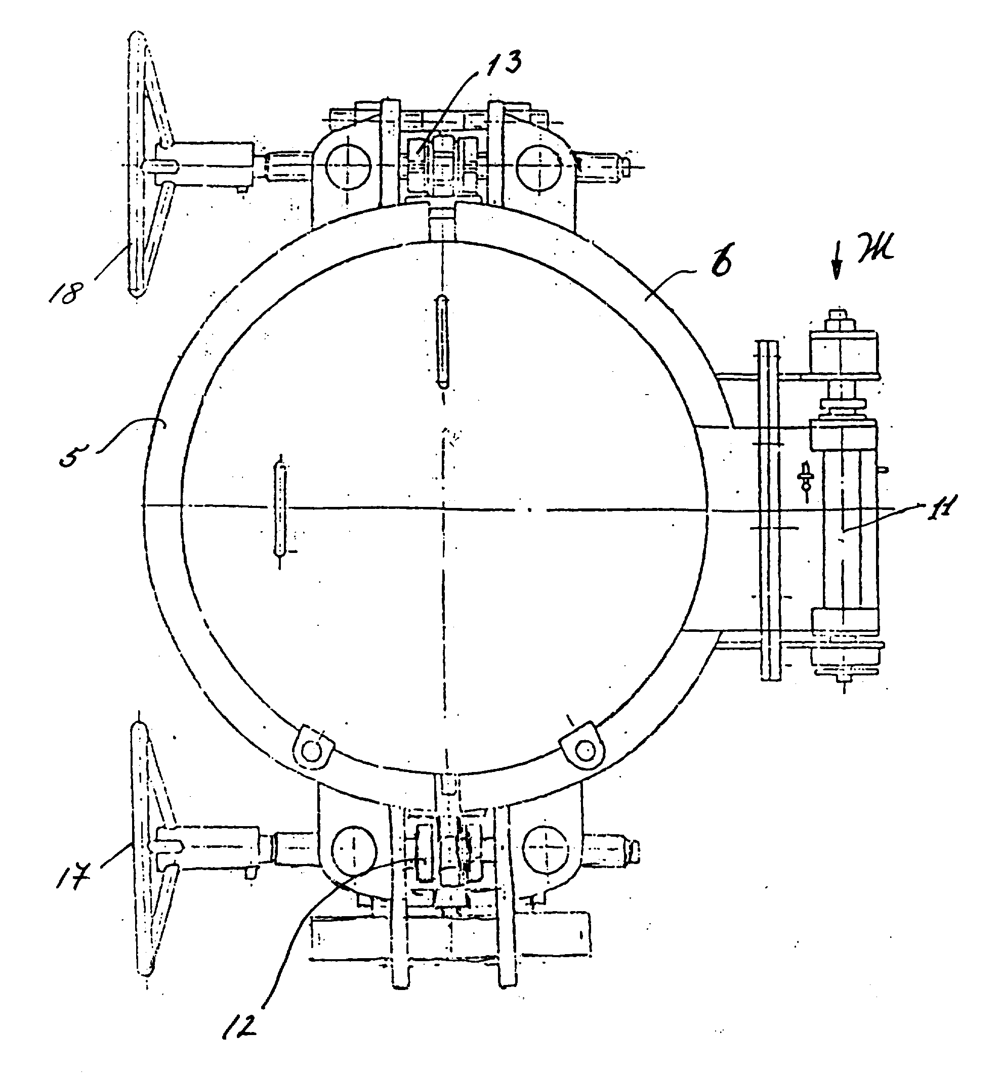
На фиг. 1 изображена общая схема расположения трубопровода и камер запуска и приема поточных снарядов (вид сбоку); на фиг.2 - тоже (вид сверху); на фиг.З - концевой затвор в сборе (вид сбоку) ; на фиг.4 - вид А на фиг.З ; на фиг.З - сечение Д-Д фиг.4; на фиг. 6 - вид Ж на фиг. 7; на фиг. 7 - вид А (увеличено) на фигЗ.In FIG. 1 shows a general arrangement of the pipeline and the launch and reception chambers of in-line projectiles (side view); figure 2 is also (top view); in Fig.Z - end valve assembly (side view); figure 4 is a view a in figure 3; in Fig.Z - section DD DD of Fig.4; in FIG. 6 is a view G in FIG. 7; in FIG. 7 - view A (enlarged) in FIG.
Концевой затвор камер для и приема поточных снарядов при экспл атации трубопроводов 1 содержит герметично закрепленный соосно камере 2 на ее свободном конце корпус 3 затвора с подвижно закрепленной на нем откидной крышкой 4. Замковый узел фиксацш4 (в рабочем положении) откидной крышки 4, выполнен в виде по крайней мере двух пoдвIiжныx полуобр ей 5 и 6 с профилированной замковой поверхностью 7 (профиль этих поверхностей обозначен одной позицией, поскольку совпадает у обоих полуобручей), образующих в рабочем положении замок с оппозитными замковым поверхностям полуобручей - замковыми поверхностями 8 и 9, выполненными в виде колцевых буртиков, соответственно на свободной торцевой части корпуса 3 затвора и по нар жному периметру крышки 4. Крышка 4 подвижно закреплена на корпусе 3 затвора посредством поворотного механизма, выполненного в виде , жестко закрепленных на корпусе кронштейнов 10 с установлеююй в них осью 11 поворота крыщки 4.The end shutter of the chambers for receiving and flowing projectiles during operation of the pipelines 1 comprises a shutter housing 3 with a hinged lid 4. The hinged latch 4 (in the working position) of the hinged lid 4 is made in the form of a hermetically fixed coaxially to the chamber 2 at its free end at least two movable half-edges 5 and 6 with a profiled locking surface 7 (the profile of these surfaces is indicated by one position, since they coincide in both half-hoops), forming a lock with opposed locks in the working position the surfaces of the semi-hoops - locking surfaces 8 and 9, made in the form of annular beads, respectively, on the free end part of the shutter body 3 and along the outer perimeter of the cover 4. The cover 4 is movably fixed to the shutter body 3 by means of a rotary mechanism made in the form of rigidly fixed to the housing of the brackets 10 with the axis of rotation of the cover 4 mounted in them 11.
На корпусе 2 камеры смонтирован также механизм привода замкового узла фиксащт откидной крышки 4 в рабочем положении, выполненный в виде кинематически связанных с концами подвижных полуобручей 5 и 6 двумя винтовыми механизмами 12 и 13, диаметрально противоположно расположенными по отношению к корпусу затвора. Каждый винтовой механизм 12 и 13 соединен с двумя концевыми частями полуобручей 5 и 6, которые охватывают торцевую часть корпуса 3 затвора.A drive mechanism of the locking assembly of the hinge cover 4 fixed in the working position is also mounted on the camera body 2, made in the form of kinematically connected to the ends of the movable half-hoops 5 and 6 by two screw mechanisms 12 and 13 diametrically opposed to the shutter body. Each screw mechanism 12 and 13 is connected to two end parts of the semi-hoops 5 and 6, which cover the end part of the shutter body 3.
Работа устройства осуществляется следуюшдм образом.The operation of the device is as follows.
Открывают камеру, предварительно раскрепив узел фиксации затвора, д.11я чего предварительно скидывают накидной фиксатор 14 с шарнирной защелки 15 и выводят ее из зацепления с пальцами 16, закреплекньши на концах полуобручей 5 и 6. Затем, вращая штурвалы 17 и18 приводят в действие винтовые механизмы 12 и 13, которые перемещая концы полуобручей отводят их от поверхности корпуса, освобождая этим кольцевые замковые буртики ( замковые поверхности 8 и 9). После раскрепления фиксирующего узла, поворотом крышки 4 вокруг вертикальной оси 11 отводят ее из рабочей зоны камеры на устье которой производят необходимые операции по запасовке или приему поточных снарядов.The chamber is opened, after having previously unfastened the shutter fixing assembly, d.11, for which the cap lock 14 is first thrown off from the hinge latch 15 and disengaged from the fingers 16, fixed at the ends of the half-hoops 5 and 6. Then, turning the steering wheels 17 and 18 actuate the screw mechanisms 12 and 13, which by moving the ends of the semi-hoops divert them from the surface of the housing, thereby freeing the annular locking beads (locking surfaces 8 and 9). After the fixing unit is unfastened, by turning the cover 4 around the vertical axis 11, it is withdrawn from the working area of the chamber at the mouth of which carry out the necessary operations for stocking or receiving in-line projectiles.
При закрытии затвора вышеописанные работы производятся в обратной последовательности.When closing the shutter, the above operations are performed in the reverse order.
За счет осуществления поворота крышки в горизонтальной плоскости, полностью исключается травматизм и аварии, связанные с падением крышки, кроме того повышается удобство в работе. Однако основное преимущество предложенного устройства, заключается в том. что за счет надежного закрепления крышки в рабочем положении по всему ее периметру, полностью исключаются аварийные ситуации, связанные с самопроизвольным открытием затвора. Кроме того, предложенная конструкция может быть легко механ11зирована за счет снабжения винтовых механизмов и узла поворота крышки электроприводами.Due to the rotation of the lid in the horizontal plane, injuries and accidents associated with the fall of the lid are completely eliminated, in addition, the convenience in operation is increased. However, the main advantage of the proposed device is. that due to reliable fastening of the lid in the working position along its entire perimeter, emergency situations associated with spontaneous opening of the shutter are completely excluded. In addition, the proposed design can be easily mechanized by supplying screw mechanisms and a cover rotation unit with electric drives.
Claims (1)
Priority Applications (1)
| Application Number | Priority Date | Filing Date | Title |
|---|---|---|---|
| RU97104949/20U RU6155U1 (en) | 1997-04-04 | 1997-04-04 | END CAMERA LOCK FOR LAUNCHING AND RECEIVING FLOW APPLIANCES WHEN OPERATING PIPELINES |
Applications Claiming Priority (1)
| Application Number | Priority Date | Filing Date | Title |
|---|---|---|---|
| RU97104949/20U RU6155U1 (en) | 1997-04-04 | 1997-04-04 | END CAMERA LOCK FOR LAUNCHING AND RECEIVING FLOW APPLIANCES WHEN OPERATING PIPELINES |
Publications (1)
| Publication Number | Publication Date |
|---|---|
| RU6155U1 true RU6155U1 (en) | 1998-03-16 |
Family
ID=48268226
Family Applications (1)
| Application Number | Title | Priority Date | Filing Date |
|---|---|---|---|
| RU97104949/20U RU6155U1 (en) | 1997-04-04 | 1997-04-04 | END CAMERA LOCK FOR LAUNCHING AND RECEIVING FLOW APPLIANCES WHEN OPERATING PIPELINES |
Country Status (1)
| Country | Link |
|---|---|
| RU (1) | RU6155U1 (en) |
-
1997
- 1997-04-04 RU RU97104949/20U patent/RU6155U1/en active
Similar Documents
| Publication | Publication Date | Title |
|---|---|---|
| US5193573A (en) | Ball valve having replaceable seals under full service pressure | |
| BR0312292A (en) | Closing for a pressure vessel and method | |
| GB2390409B (en) | Closure for a pressure vessel and method | |
| US4139118A (en) | Pressure vessel safety interlock | |
| US3340890A (en) | Viewing port with removable window | |
| ES2083102T3 (en) | ROTARY VALVES AND THEIR SEALED CLOSURE. | |
| RU6155U1 (en) | END CAMERA LOCK FOR LAUNCHING AND RECEIVING FLOW APPLIANCES WHEN OPERATING PIPELINES | |
| JP2003511631A (en) | Pressure vessel closure system | |
| US3845976A (en) | Casket locking mechanism | |
| RU10828U1 (en) | DEVICE FOR OVERLAPPING PIPELINE TAP | |
| US8322556B2 (en) | Closure for a vessel | |
| CN208951340U (en) | A kind of control ball valve with opening and closing device | |
| CN2420509Y (en) | Man hole door of engineering device | |
| RU2129923C1 (en) | Chamber for injecting and receiving flow tools in operation of pipe lines | |
| RU171009U1 (en) | QUICK CLOSE END SHUTTER | |
| RU2129922C1 (en) | Chamber for injecting and receiving flow tools during operation of pipe lines | |
| DE2406703A1 (en) | Pipe valve, esp. for gas ducts on blast furnaces - contg. rotary pipe section on spherical seat with multiple seals | |
| SU1379442A1 (en) | Drum hatch closure | |
| CN212480139U (en) | Novel screw mouth gate valve | |
| CN208611842U (en) | Extractor clamp ring top sheave device | |
| SU976163A1 (en) | Vessel quick-acting bayonet gate | |
| US2437083A (en) | Pipe coupling | |
| CN208364086U (en) | Ram preventer locking device | |
| US2738804A (en) | Strainer valve | |
| DE2226097C3 (en) | Rotatable, gas-tight shut-off valve for gas outlet pipes of electric melting furnaces |