RU57787U1 - FRICTION HINGE FOR OPENING OUTSIDE WINDOWS - Google Patents
FRICTION HINGE FOR OPENING OUTSIDE WINDOWS Download PDFInfo
- Publication number
- RU57787U1 RU57787U1 RU2006121223/22U RU2006121223U RU57787U1 RU 57787 U1 RU57787 U1 RU 57787U1 RU 2006121223/22 U RU2006121223/22 U RU 2006121223/22U RU 2006121223 U RU2006121223 U RU 2006121223U RU 57787 U1 RU57787 U1 RU 57787U1
- Authority
- RU
- Russia
- Prior art keywords
- slider
- gasket
- guide
- additional
- lever
- Prior art date
Links
Abstract
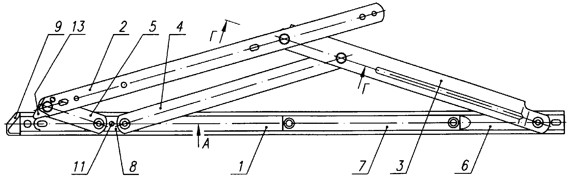
Полезная модель относится к строительству, может быть использована в окнах с откидывающимися створками и предназначена для осуществления естественной вентиляции путем открывания верхнеподвесных окон наружу. Фрикционная петля для открывающихся наружу окон выполнена в виде консольно-рычажного механизма, содержащего направляющую 1 Сообразного сечения, планку 2, опорный рычаг 3, промежуточный рычаг 4 и дополнительный рычаг 5. Направляющая 1 и планка 2 неподвижно закреплены соответственно на раме и створке окна. В нижней части направляющей 1 выполнен участок 6 с выштамповками и установлен упор 7, а в верхней части с возможностью возвратно-поступательного перемещения установлен ползун 8 П-образного сечения и жестко закреплен фиксирующий наконечник 9. На участке 6 шарнирно закреплен конец опорного рычага 3, а на ползуне 8 шарнирно закреплены концы промежуточного и дополнительного рычагов 4 и 5 соответственно. Другие концы опорного рычага 3 и дополнительного рычага 5 шарнирно закреплены на планке 2, а противоположный конец промежуточного рычага 4 шарнирно соединен с опорным рычагом 3. Внутри ползуна 8 размещена прокладка 10 с образованием зазора между торцами боковых стенок ползуна 8 и направляющей 1. В центральной части ползуна 8 и прокладки 10 выполнено отверстие под регулировочный винт 11, причем отверстие в прокладке 10-глухое. Симметрично относительно центрального отверстия на ползуне 8 и прокладке 10 выполнены два сквозных отверстия под шарниры 12 промежуточного и дополнительного рычагов 4 и 5. Планка 2 снабжена фиксирующим язычком 13, закрепленным на ее верхнем конце. В местах шарнирных соединений рычагов 3, 4 и 5 установлены шайбы 14. Создана надежная конструкция фрикционной петли с высокими эксплуатационными качествами, позволяющими за счет регулировки тормозного усилия петли регулировать промежуточный угол открывания створки. 5 ил.The utility model relates to construction, can be used in windows with hinged flaps, and is designed for natural ventilation by opening the top-hung windows to the outside. The friction loop for the outward-opening windows is made in the form of a cantilever mechanism containing a guide 1 of a suitable cross-section, a strap 2, a support lever 3, an intermediate lever 4 and an additional lever 5. The guide 1 and the strap 2 are fixedly mounted respectively on the frame and the sash of the window. Section 6 with stampings is made in the lower part of the guide 1 and the stop 7 is installed, and in the upper part with the possibility of reciprocating movement, a U-shaped slider 8 is installed and a fixing tip 9 is rigidly fixed. The end of the support arm 3 is pivotally fixed on the slider 8, the ends of the intermediate and additional levers 4 and 5 are pivotally fixed. The other ends of the support arm 3 and the additional arm 5 are pivotally fixed to the bar 2, and the opposite end of the intermediate arm 4 is pivotally connected to the support arm 3. Inside the slider 8, a gasket 10 is placed with a gap between the ends of the side walls of the slider 8 and the guide 1. In the central part the slider 8 and the gasket 10 made a hole for the adjusting screw 11, and the hole in the gasket 10 is deaf. Symmetrically with respect to the central hole on the slider 8 and the gasket 10, two through holes are made for the hinges 12 of the intermediate and additional levers 4 and 5. The bar 2 is provided with a locking tongue 13 fixed to its upper end. Washers 14 are installed at the joints of the levers 3, 4, and 5. A reliable friction loop design with high performance has been created, which allows adjusting the intermediate opening angle of the sash by adjusting the braking force of the hinge. 5 ill.
Description
Полезная модель относится к строительству, может быть использована в окнах с откидывающимися створками и предназначена для осуществления естественной вентиляции путем открывания верхнеподвесных окон наружу.The utility model relates to construction, can be used in windows with hinged flaps, and is designed for natural ventilation by opening the top-hung windows to the outside.
Известно устройство для откидывания оконной створки, включающее толкательные штанги, размещенные по периметру в профильном пазу с нависающими краями, и отклоняющую штангу, шарнирно закрепленную одной стороной на петле створки, а другой - на опорном неподвижном элементе, установленном на створке (патент СССР №632308, Мкл2 Е 06 В 3/50, опубл. 05.11.78).A device for folding the sash, including push rods placed around the perimeter in the profile groove with overhanging edges, and a deflecting rod, pivotally mounted on one side on the hinge of the sash, and the other on the supporting fixed element mounted on the sash (USSR patent No. 632308, ΜL 2 E 06 V 3/50, publ. 05.11.78).
Наиболее близким по совокупности существенных признаков к заявляемому техническому решению является усовершенствованное окно, в котором оконный переплет имеет возможность вращения относительно рамы с помощью консольно-рычажного механизма, содержащего опорный рычаг, один конец которого шарнирно связан со створкой окна, а другой конец снабжен втулкой и установлен в канавке рамы с возможностью поворота и возвратно-поступательного перемещения, промежуточный рычаг, один конец которого шарнирно соединен с опорным рычагом, а другой - с рамой окна и фиксирующий элемент, кроме того, в раме выполнена дополнительная канавка, параллельная канавке опорного рычага, концы которой продолжаются в поперечном направлении и открыты в окружающее пространство, в дополнительной канавке перемещается направляющая втулка, обеспечивающая фиксацию створки с помощью фиксирующего элемента (патент РФ №2144974, МПК7 Е 06 В 3/40, опубл. 27.01.00).The closest set of essential features to the claimed technical solution is an improved window in which the window cover has the ability to rotate relative to the frame using a cantilever mechanism containing a support lever, one end of which is pivotally connected to the sash of the window, and the other end is provided with a sleeve and installed in the groove of the frame with the possibility of rotation and reciprocating movement, an intermediate lever, one end of which is pivotally connected to the support lever, and the other to the frames the second window and the locking element, in addition, an additional groove is made in the frame parallel to the groove of the support arm, the ends of which extend laterally and open into the surrounding space, the guide sleeve is moved in the additional groove to secure the leaf using the locking element (RF patent No. 2144974, IPC7 E 06 B 3/40, publ. 27.01.00).
Недостатками известного технического решения являются невысокая надежность конструкции, а также низкие эксплутационные характеристики.The disadvantages of the known technical solutions are the low reliability of the design, as well as low operational characteristics.
Была поставлена задача: создать надежную конструкцию с высокими эксплуатационными качествами, позволяющими за счет регулировки The task was set: to create a reliable design with high performance, allowing through adjustment
тормозного усилия петли регулировать промежуточный угол открывания створки.hinge force of the loop to adjust the intermediate opening angle of the sash.
Поставленная задача решается за счет того, что фрикционная петля для открывающихся наружу окон, выполненная в виде консольно-рычажного механизма, содержащего опорный рычаг, один конец которого шарнирно связан со створкой окна, а другой с возможностью поворота соединен с рамой окна, промежуточный рычаг, один конец которого шарнирно соединен с опорным рычагом, а другой - с рамой окна с возможностью направленного перемещения, и фиксирующий элемент, дополнительно снабжена направляющей С-образного сечения и планкой, неподвижно закрепленными соответственно на раме и створке, и дополнительным рычагом, в нижней части направляющей выполнен участок с выштамповками и установлен упор, а в верхней части с возможностью возвратно-поступательного перемещения установлен ползун П-образного сечения и жестко закреплен фиксирующий наконечник, на участке с выштамповками и ползуне шарнирно закреплены концы опорного рычага, промежуточного и дополнительного рычагов соответственно, другие концы опорного и дополнительного рычагов шарнирно закреплены на планке, при этом внутри ползуна размещена прокладка с образованием зазора между торцами боковых стенок ползуна и направляющей, на ползуне и прокладке выполнено центральное отверстие под регулировочный винт, причем, отверстие в прокладке - глухое, и расположенные симметрично относительно центрального отверстия два сквозных отверстия под шарниры промежуточного и дополнительного рычагов, кроме того, верхний конец планки снабжен фиксирующим язычком, а в местах шарнирных соединений установлены шайбы.The problem is solved due to the fact that the friction loop for the windows opening outward, made in the form of a cantilever-lever mechanism containing a support lever, one end of which is pivotally connected to the window sash, and the other is rotatably connected to the window frame, an intermediate lever, one the end of which is pivotally connected to the support arm, and the other to the window frame with the possibility of directional movement, and the locking element is additionally equipped with a C-shaped guide and a strap fixedly fixed respectively, on the frame and the sash, and an additional lever, a section with punchings is made in the lower part of the guide and a stop is installed, and a U-shaped slider is installed in the upper part with the possibility of reciprocating movement and a fixing tip is rigidly fixed, in the area with stampings and a slider the ends of the support arm, intermediate and additional levers are pivotally fixed, the other ends of the support and additional levers are pivotally fixed to the bar, while the size of the slide A gasket is provided with a gap between the ends of the side walls of the slider and the guide, a central hole for the adjustment screw is made on the slide and gasket, moreover, the hole in the gasket is blind and two through holes are located symmetrically relative to the central hole for the hinges of the intermediate and additional levers, in addition , the upper end of the strap is equipped with a locking tab, and washers are installed at the joints.
Выполнение петли с направляющей С-образного сечения и планкой, неподвижно закрепленными соответственно на раме и створке, и дополнительным рычагом, а также то, что в нижней части направляющей выполнен участок с выштамповками и установлен упор, а в верхней части с возможностью возвратно-поступательного перемещения установлен ползун П-образного сечения и жестко закреплен фиксирующий наконечник, на Making a loop with a C-shaped guide and a bar fixedly mounted respectively on the frame and sash, and an additional lever, as well as the fact that in the lower part of the guide there is a section with stampings and a stop, and in the upper part with the possibility of reciprocating movement a U-shaped slider is installed and a fixing tip is rigidly fixed
участке с выштамповками и ползуне шарнирно закреплены концы опорного рычага, промежуточного и дополнительного рычагов соответственно, другие концы опорного и дополнительного рычагов шарнирно закреплены на планке, позволяет повысить надежность конструкции.the section with punching and slider the ends of the support arm, intermediate and additional levers are pivotally fixed, the other ends of the support and additional levers are pivotally mounted on the bar, which improves the reliability of the design.
Размещение внутри ползуна прокладки с образованием зазора между торцами боковых стенок ползуна и направляющей, выполнение в центральной части ползуна и прокладки отверстия под регулировочный винт, причем отверстие в прокладке - глухое, и расположенных симметрично относительно центрального отверстия двух сквозных отверстий под шарниры промежуточного и дополнительного рычагов, а также установка в местах шарнирных соединений шайб позволяет регулировать тормозное усилие за счет увеличения силы трения между прокладкой и направляющей, что обеспечивает плавность движения створки и ее фиксацию при любом промежуточном угле открывания, т.о. повысить эксплуатационные качества окна.Placement of a gasket inside the slider with the formation of a gap between the ends of the side walls of the slider and the guide, making a hole for the adjusting screw in the central part of the slide and gasket, the hole in the gasket being blind, and two through holes for the hinges of the intermediate and additional levers located symmetrically relative to the central hole as well as the installation of washers in places of hinge joints, it is possible to adjust the braking force by increasing the friction force between the gasket and the guide, h to provide smooth motion and its sash lock at any intermediate angle of opening, thus improve window performance.
Проведенный анализ уровня техники, включающий поиск по патентным и научно-техническим источникам информации, позволил установить, что аналог, характеризующийся признаками, тождественными всем существенным признакам заявленного технического решения, не обнаружен. На основании вышеизложенного можно сделать вывод, что заявляемое техническое решение соответствует критерию «новизна». Заявляемое техническое решение поясняется чертежами:The analysis of the prior art, including a search by patent and scientific and technical sources of information, made it possible to establish that an analogue, characterized by features identical to all the essential features of the claimed technical solution, was not found. Based on the foregoing, we can conclude that the claimed technical solution meets the criterion of "novelty." The claimed technical solution is illustrated by the drawings:
фиг.1 - фрикционная петля для открывающихся наружу окон, общий вид;figure 1 - friction loop for outward opening windows, General view;
фиг.2 - сечение А-А на фиг.1 (увеличено 2:1);figure 2 - section aa in figure 1 (increased 2: 1);
фиг.3 - сечение Б-Б на фиг.1 (увеличено 2:1);figure 3 - section bB in figure 1 (increased 2: 1);
фиг.4 - сечение В-В на фиг.1 (увеличено 2:1);figure 4 - section bb in figure 1 (enlarged 2: 1);
фиг.5 - сечение Г-Г на фиг.1 (увеличено 2:1, повернуто). Фрикционная петля для открывающихся наружу окон выполнена в виде консольно-рычажного механизма, содержащего направляющую 1 С-образного figure 5 - section GG in figure 1 (increased 2: 1, rotated). The friction loop for the outward opening windows is made in the form of a cantilever mechanism containing a guide 1 C-shaped
сечения, планку 2, опорный рычаг 3, промежуточный рычаг 4 и дополнительный рычаг 5.sections, strap 2, support arm 3, intermediate arm 4 and additional arm 5.
Направляющая 1 и планка 2 неподвижно закреплены соответственно на раме и створке окна.Guide 1 and strap 2 are fixedly mounted respectively on the frame and the sash of the window.
В нижней части направляющей 1 выполнен участок 6 с выштамповками и установлен упор 7, а в верхней части с возможностью возвратно-поступательного перемещения установлен ползун 8 П-образного сечения и жестко закреплен фиксирующий наконечник 9.In the lower part of the guide 1, a section 6 with stampings is made and a stop 7 is installed, and in the upper part with the possibility of reciprocating movement, a slider 8 of a U-shaped section is installed and a fixing tip 9 is rigidly fixed.
На участке 6 шарнирно закреплен конец опорного рычага 3, а на ползуне 8 шарнирно закреплены концы промежуточного и дополнительного рычагов 4 и 5 соответственно. Другие концы опорного рычага 3 и дополнительного рычага 5 шарнирно закреплены на планке 2, а противоположный конец промежуточного рычага 4 шарнирно соединен с опорным рычагом 3.In section 6, the end of the support arm 3 is pivotally fixed, and on the slider 8, the ends of the intermediate and additional levers 4 and 5 are pivotally fixed. The other ends of the support arm 3 and the additional arm 5 are pivotally fixed to the bar 2, and the opposite end of the intermediate arm 4 is pivotally connected to the support arm 3.
Внутри ползуна 8 размещена прокладка 10 с образованием зазора между торцами боковых стенок ползуна 8 и направляющей 1. В центральной части ползуна 8 и прокладки 10 выполнено отверстие под регулировочный винт 11, причем отверстие в прокладке 10 - глухое. Симметрично относительно центрального отверстия на ползуне 8 и прокладке 10 выполнены два сквозных отверстия под шарниры 12 промежуточного и дополнительного рычагов 4 и 5.A gasket 10 is placed inside the slider 8 to form a gap between the ends of the side walls of the slider 8 and the guide 1. In the central part of the slider 8 and the gasket 10, a hole for the adjusting screw 11 is made, and the hole in the gasket 10 is blind. Symmetrically relative to the Central hole on the slider 8 and the gasket 10 made two through holes for the hinges 12 of the intermediate and additional levers 4 and 5.
Планка 2 снабжена фиксирующим язычком 13, закрепленным на ее верхнем конце.The strap 2 is equipped with a locking tab 13, mounted on its upper end.
В местах шарнирных соединений рычагов 3, 4 и 5 установлены шайбы 14.In places of articulation of levers 3, 4 and 5 washers 14 are installed.
Фрикционные петли устанавливают справой и левой стороны окна между двумя параллельными поверхностями в зазоре между фальцами рамы и створки, при этом верхние части петель должны быть установлены на расстоянии около двух миллиметров от верхних углов рамы. Петли фиксируют винтами М5 с цилиндрическими головками, которые должны вкручиваться в резьбовые вставки или вкладыши на глубину резьбы не менее Friction loops are installed on the right and left sides of the window between two parallel surfaces in the gap between the folds of the frame and the sash, while the upper parts of the hinges should be installed at a distance of about two millimeters from the upper corners of the frame. The hinges are fixed with M5 screws with cylindrical heads, which must be screwed into threaded inserts or bushings to a thread depth of at least
6 мм. При открывании окна планка 2 со створкой движется по сложной траектории благодаря рычагам 3, 4, 5. При этом рычаг 3 поворачивается вокруг оси шарнира, соединяющего его с участком 6, а ползун 8 смещается по направляющей 1 вниз до упора 7. Шайбы 14, а также прокладка 10 работают в качестве фрикционов и обеспечивают плавность движения. При закрывании створки язычок 13 входит в фиксирующий наконечник 9, чем обеспечивается прижим створки к раме.6 mm. When the window is opened, the lath 2 with the sash moves along a complex path due to the levers 3, 4, 5. At the same time, the lever 3 rotates around the axis of the hinge connecting it to section 6, and the slider 8 moves along the guide 1 down to the stop 7. Washers 14, and also gasket 10 operate as friction clutches and ensure smooth movement. When closing the sash, the tongue 13 is included in the fixing tip 9, which ensures that the sash is pressed against the frame.
Для обеспечения надежной фиксации створки при любом угле открывания регулируют тормозное усилие следующим образом. При затягивании регулировочного винта 11 он давит на прокладку 10, вследствие чего увеличивается сила трения между прокладкой 10 и направляющей 1, а поскольку прокладка 10 закреплена на ползуне 8, то увеличивается усилие при раскрывании (закрывании) створки окна. При достаточном усилии открывания (закрывания) створку окна можно оставлять открытой не только в конечном положении, но и при любом угле открывания.To ensure reliable fixation of the sash at any opening angle, the brake force is adjusted as follows. When tightening the adjusting screw 11, it presses on the gasket 10, as a result of which the frictional force between the gasket 10 and the guide 1 increases, and since the gasket 10 is mounted on the slider 8, the force increases when the window sash is opened (closed). With sufficient force to open (close) the window sash can be left open not only in the final position, but also at any opening angle.
Заявляемое техническое решение позволяет создать надежную конструкцию фрикционной петли с высокими эксплуатационными качествами, предназначенную для осуществления естественной вентиляции путем открывания верхнеподвесных окон наружу.The claimed technical solution allows you to create a reliable design of the friction loop with high performance, designed for natural ventilation by opening the top-hung windows to the outside.
Заявляемая фрикционная петля для открывающихся наружу окон соответствует требованию промышленной применимости и может быть выполнена на стандартном технологическом оборудовании с использованием современных материалов и технологий.The inventive friction loop for windows opening outward meets the requirement of industrial applicability and can be performed on standard processing equipment using modern materials and technologies.
Claims (1)
Priority Applications (1)
| Application Number | Priority Date | Filing Date | Title |
|---|---|---|---|
| RU2006121223/22U RU57787U1 (en) | 2006-06-14 | 2006-06-14 | FRICTION HINGE FOR OPENING OUTSIDE WINDOWS |
Applications Claiming Priority (1)
| Application Number | Priority Date | Filing Date | Title |
|---|---|---|---|
| RU2006121223/22U RU57787U1 (en) | 2006-06-14 | 2006-06-14 | FRICTION HINGE FOR OPENING OUTSIDE WINDOWS |
Publications (1)
| Publication Number | Publication Date |
|---|---|
| RU57787U1 true RU57787U1 (en) | 2006-10-27 |
Family
ID=37439580
Family Applications (1)
| Application Number | Title | Priority Date | Filing Date |
|---|---|---|---|
| RU2006121223/22U RU57787U1 (en) | 2006-06-14 | 2006-06-14 | FRICTION HINGE FOR OPENING OUTSIDE WINDOWS |
Country Status (1)
| Country | Link |
|---|---|
| RU (1) | RU57787U1 (en) |
Cited By (3)
| Publication number | Priority date | Publication date | Assignee | Title |
|---|---|---|---|---|
| RU2724842C1 (en) * | 2019-08-21 | 2020-06-25 | Общество с ограниченной ответственностью "Летний сад" (ООО "Летний сад") | Attic window (embodiments) |
| RU201256U1 (en) * | 2020-09-15 | 2020-12-07 | Общество с ограниченной ответственностью "Летний сад" (ООО "Летний сад") | FRICTION HINGE FOR OUTWARD OPENING UPPER SUSPENDED WINDOWS |
| WO2022060249A1 (en) | 2020-09-15 | 2022-03-24 | Андрей Борисович СТРЕПЕТОВ | Friction hinge for top-hung outwardly opening windows |
-
2006
- 2006-06-14 RU RU2006121223/22U patent/RU57787U1/en active IP Right Revival
Cited By (4)
| Publication number | Priority date | Publication date | Assignee | Title |
|---|---|---|---|---|
| RU2724842C1 (en) * | 2019-08-21 | 2020-06-25 | Общество с ограниченной ответственностью "Летний сад" (ООО "Летний сад") | Attic window (embodiments) |
| WO2021034225A1 (en) * | 2019-08-21 | 2021-02-25 | Андрей Борисович СТРЕПЕТОВ | Mansard window |
| RU201256U1 (en) * | 2020-09-15 | 2020-12-07 | Общество с ограниченной ответственностью "Летний сад" (ООО "Летний сад") | FRICTION HINGE FOR OUTWARD OPENING UPPER SUSPENDED WINDOWS |
| WO2022060249A1 (en) | 2020-09-15 | 2022-03-24 | Андрей Борисович СТРЕПЕТОВ | Friction hinge for top-hung outwardly opening windows |
Similar Documents
| Publication | Publication Date | Title |
|---|---|---|
| RU109189U1 (en) | DOUBLE-WINDOW WINDOW WITH WINDOWS AND LOWER SURFACES, DESIGN AND REGULATORY WINDOWS | |
| US7004515B2 (en) | Fenestration locking system | |
| CA2911872A1 (en) | Around-the-corner multi-point lock mechanism for casement and awning windows | |
| EP1918498B1 (en) | Hidden hinge | |
| RU57787U1 (en) | FRICTION HINGE FOR OPENING OUTSIDE WINDOWS | |
| US4113293A (en) | Adjustable door latch striker | |
| RU2016122909A (en) | Fittings for at least lifting, and preferably also a movable window or door sash | |
| EP3540162B1 (en) | Opening action supporting device and opening section device | |
| EP3321458A1 (en) | A hinge arrangement, in particular a hidden hinge arrangement | |
| US10927580B2 (en) | Door closers | |
| EE04621B1 (en) | Closure assembly for a window or door with a movable window or door leaf | |
| RU57784U1 (en) | HINGE FOR DOOR | |
| CN211115505U (en) | Hidden vertical hinged top-hung hardware system | |
| RU121849U1 (en) | HINGE OPENING MECHANISM | |
| CN110080656A (en) | It is concealed to be opened flat hanging hardware system | |
| WO2020199082A1 (en) | Shower door | |
| CN219138749U (en) | Flat-open hinge for curtain wall | |
| RU2519982C2 (en) | Loop for rotary joint of leaf with frame | |
| RU156532U1 (en) | SPRING DOOR LOOP FOR SPRING DOOR | |
| RU94611U1 (en) | THE LOOP | |
| CN213869327U (en) | Lock box structure for inward opening and inward reversing door and window | |
| WO2022060249A1 (en) | Friction hinge for top-hung outwardly opening windows | |
| DE19804355C2 (en) | Concealed fitting for windows, doors or the like | |
| RU156611U1 (en) | HINGER-CLOSER FOR A PLASTIC DOOR WITH A HYDRAULIC AXLE | |
| EP2251516B1 (en) | Door operating mechanism |
Legal Events
| Date | Code | Title | Description |
|---|---|---|---|
| MM1K | Utility model has become invalid (non-payment of fees) |
Effective date: 20090615 |
|
| NF1K | Reinstatement of utility model |
Effective date: 20110320 |
|
| MM1K | Utility model has become invalid (non-payment of fees) |
Effective date: 20120615 |
|
| NF1K | Reinstatement of utility model |
Effective date: 20150410 |