RU525373C - Planar cathode-luminescent indicator - Google Patents
Planar cathode-luminescent indicator Download PDFInfo
- Publication number
- RU525373C RU525373C SU1999313A RU525373C RU 525373 C RU525373 C RU 525373C SU 1999313 A SU1999313 A SU 1999313A RU 525373 C RU525373 C RU 525373C
- Authority
- RU
- Russia
- Prior art keywords
- electrodes
- groups
- indicator
- cathode
- planar cathode
- Prior art date
Links
- 239000000126 substance Substances 0.000 claims description 3
- 239000011159 matrix material Substances 0.000 description 2
- 238000005136 cathodoluminescence Methods 0.000 description 1
- 229910010293 ceramic material Inorganic materials 0.000 description 1
- 239000004020 conductor Substances 0.000 description 1
- 238000010894 electron beam technology Methods 0.000 description 1
- 239000011521 glass Substances 0.000 description 1
- 238000002955 isolation Methods 0.000 description 1
- 238000000034 method Methods 0.000 description 1
- 238000010899 nucleation Methods 0.000 description 1
- 230000000007 visual effect Effects 0.000 description 1
Images
Landscapes
- Devices For Indicating Variable Information By Combining Individual Elements (AREA)
Description
Изобретение относится к низковольтным вакуумным средствам отображения информации на основе катодолюминесценции и может применяться для создания цифровых и буквенно-цифровых индикаторов, универсальных матричных панелей для визуального отображения любой информации - текстовой, знаковой, графической, отсчетных устройств аналоговых и дискретно-аналоговых измерительных приборов и т.д. The invention relates to low-voltage vacuum means for displaying information based on cathodoluminescence and can be used to create digital and alphanumeric indicators, universal matrix panels for the visual display of any information - text, character, graphic, reading devices of analog and discrete-analog measuring devices, etc. d.
Известны индикаторы, представляющие собой приборы с ограниченным (порядка 20) количеством изолированных друг от друга индикаторных сегментов-анодов, общим оксидным катодом прямого накала и общей сеткой, которая предназначена для рассеивания электронного потока и создания условий равномерного засева электронами светоизлучающих элементов. При использовании динамических методов индикации сетка служит вторым (кроме анодного) управляющим электродом. Indicators are known, which are devices with a limited (about 20) number of indicator segments-anodes isolated from each other, a common oxide direct cathode and a common grid, which is designed to disperse the electron beam and create conditions for uniform electron-seeding of light-emitting elements by electrons. When using dynamic display methods, the grid serves as the second (except for the anode) control electrode.
Известен также планарный катодолюминесцентный индикатор, содержащий катод и две группы электродов, расположенных в одной плоскости. Also known is a planar cathodoluminescent indicator containing a cathode and two groups of electrodes located in the same plane.
Недостатком этих индикаторов является высокая потребляемая мощность управления. The disadvantage of these indicators is the high power consumption of the control.
Для снижения потребляемой мощности управления в предлагаемом индикаторе электроды обеих групп расположены попарно, образуя светоизлучающие сегменты, причем электроды покрыты катодолюминесцентным веществом. To reduce the power consumption of the control in the proposed indicator, the electrodes of both groups are arranged in pairs, forming light-emitting segments, and the electrodes are coated with a cathodoluminescent substance.
Зазор между электродами гарантирует электрическую изоляцию их друг от друга и практически не влияет на четкость индикации, причем электроды одной из групп могут быть электрически соединены между собой. The gap between the electrodes ensures their electrical isolation from each other and practically does not affect the clarity of the indication, and the electrodes of one of the groups can be electrically connected to each other.
Электроды обеих групп могут быть выполнены одинаковыми по форме. The electrodes of both groups can be made identical in shape.
Электроды одной из групп могут быть расположены вокруг электродов другой группы. The electrodes of one group can be located around the electrodes of another group.
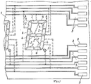
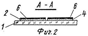
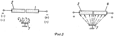
На фиг. 1 показан описываемый цифровой индикатор; на фиг.2 - разрез по А-А на фиг.1; на фиг.3 - схематичное изображение принципа свечения индикатора. In FIG. 1 shows the described digital indicator; figure 2 is a section along aa in figure 1; figure 3 is a schematic representation of the principle of the glow of the indicator.
Индикатор содержит набор сегментов (электродов), расположенных в виде либо цифры восемь, либо набора последовательно расположенных групп сегментов, либо групп сегментов, расположенных последовательно в горизонтальном и вертикальном направлениях (матричное расположение). The indicator contains a set of segments (electrodes) arranged in the form of either the numbers eight, or a set of consecutively arranged groups of segments, or groups of segments arranged consecutively in horizontal and vertical directions (matrix arrangement).
На изолирующую основу 1, выполненную, например, из керамического материала или прозрачного стекла, нанесены сегменты, состоящие из двух изолированных электродов - анода и второго управляющего электрода. Анод 2 каждого сегмента выведен на соответствующий селекторный вывод 3, расположенный на изолирующей основе 1. Вторые управляющие электроды 4 каждого сегмента электрически соединены и имеют один общий селекторный вывод 5 для данного разряда цифр. On the
Каждый цифровой разряд имеет собственный селекторный вывод 5 от вторых управляющих электродов данного разряда. Each digital discharge has its
Одноименные аноды 2 разрядов электрически соединены (для работы в мультиплексном режиме) и выведены на соответствующий селекторный вывод 3. The same-name anodes of 2 bits are electrically connected (for operation in multiplex mode) and output to the
На изолирующую основу 1 (см.фиг.2), которая может быть прозрачной внешней оболочкой индикатора, нанесены управляющие электроды 2 и 4. В случае выполнения этих электродов из прозрачного проводящего материала изображение можно просматривать не только на отражение, но и на просвет с внешней стороны изолирующей оболочки индикатора. Сверху на проводящий слой управляющих электродов нанесен слой 6 люминесцентного вещества. On the insulating base 1 (see Fig. 2), which can be a transparent outer shell of the indicator,
При подаче на оба или один (любой) из двух электродов отрицательного напряжения электронный поток с катода 7 не достигает индикаторного сегмента. В этом случае сегмент находится в "запертом" состоянии и свечение сегмента отсутствует. When applying to both or one (any) of the two electrodes of negative voltage, the electron stream from the
Свечение сегмента наблюдается только в случае подачи положительного напряжения на оба управляющих электрода. The glow of the segment is observed only if a positive voltage is applied to both control electrodes.
Claims (4)
Priority Applications (1)
| Application Number | Priority Date | Filing Date | Title |
|---|---|---|---|
| SU1999313 RU525373C (en) | 1974-03-06 | 1974-03-06 | Planar cathode-luminescent indicator |
Applications Claiming Priority (1)
| Application Number | Priority Date | Filing Date | Title |
|---|---|---|---|
| SU1999313 RU525373C (en) | 1974-03-06 | 1974-03-06 | Planar cathode-luminescent indicator |
Publications (1)
| Publication Number | Publication Date |
|---|---|
| RU525373C true RU525373C (en) | 1995-01-20 |
Family
ID=30439772
Family Applications (1)
| Application Number | Title | Priority Date | Filing Date |
|---|---|---|---|
| SU1999313 RU525373C (en) | 1974-03-06 | 1974-03-06 | Planar cathode-luminescent indicator |
Country Status (1)
| Country | Link |
|---|---|
| RU (1) | RU525373C (en) |
Cited By (1)
| Publication number | Priority date | Publication date | Assignee | Title |
|---|---|---|---|---|
| RU2258971C2 (en) * | 2003-10-17 | 2005-08-20 | Федеральное Государственное Унитарное Предприятие Научно-Исследовательский Институт "Волга" | Single-layer layout of anode-board electrodes in cathode-ray fluorescent display |
-
1974
- 1974-03-06 RU SU1999313 patent/RU525373C/en active
Non-Patent Citations (2)
| Title |
|---|
| Патент Англии N 1166176, кл. H 01D, 1967. * |
| Патент США N 3668466, кл. 315-169 Т, 1972. * |
Cited By (1)
| Publication number | Priority date | Publication date | Assignee | Title |
|---|---|---|---|---|
| RU2258971C2 (en) * | 2003-10-17 | 2005-08-20 | Федеральное Государственное Унитарное Предприятие Научно-Исследовательский Институт "Волга" | Single-layer layout of anode-board electrodes in cathode-ray fluorescent display |
Similar Documents
| Publication | Publication Date | Title |
|---|---|---|
| US3742279A (en) | Segmented electrode display panel having closed structure | |
| US3418509A (en) | Electrical discharge character indicator tube | |
| GB1496442A (en) | Luminous discharge display devices | |
| GB1085880A (en) | Character display panel | |
| GB1219446A (en) | Gaseous glow indicator tube | |
| US3201634A (en) | Electron tube for indicating symbols, letters, numerals, and the like | |
| GB838078A (en) | Thermometer type voltage indicator tube | |
| US3886390A (en) | Buttable, gaseous discharge, display panel including electrodes providing a dot matrix display | |
| GB1302582A (en) | ||
| RU525373C (en) | Planar cathode-luminescent indicator | |
| GB2062952A (en) | Cathodoluminescent opto-electronic display devices | |
| US3996490A (en) | Buttable flat panel display module | |
| US3735183A (en) | Gaseous discharge display device with a layer of electrically resistive material | |
| US3136911A (en) | High vacuum display device | |
| US3582979A (en) | Gaseous discharge display device with interconnecting structure for the electrodes | |
| US3825791A (en) | Field-effect storage tube | |
| RU2137246C1 (en) | Multicolored cathode-luminescent screen of matrix type | |
| SU1714718A1 (en) | Vacuum luminescent indicator | |
| US3657587A (en) | Alpha-numeric indicator | |
| US3849686A (en) | Plasma display panel comprising a first external electrode for each digit and a second external electrode for each segment | |
| RU2173908C1 (en) | Cathodic luminescent matrix screen | |
| US4049993A (en) | Multi-digit fluorescent display tube with inclined filament cathode | |
| US3903448A (en) | Multiple character flat panel display device | |
| GB806510A (en) | Improvements in or relating to colour-television cathode-ray tubes | |
| GB1310643A (en) | Electron tubes for character display |