RU42657U1 - SAMPLING DEVICE FOR EMISSION SPECTRAL ANALYSIS (OPTIONS) - Google Patents
SAMPLING DEVICE FOR EMISSION SPECTRAL ANALYSIS (OPTIONS)Info
- Publication number
- RU42657U1 RU42657U1 RU2004127043/22U RU2004127043U RU42657U1 RU 42657 U1 RU42657 U1 RU 42657U1 RU 2004127043/22 U RU2004127043/22 U RU 2004127043/22U RU 2004127043 U RU2004127043 U RU 2004127043U RU 42657 U1 RU42657 U1 RU 42657U1
- Authority
- RU
- Russia
- Prior art keywords
- possibility
- funnel
- base
- sampling
- electrode
- Prior art date
Links
- 238000005070 sampling Methods 0.000 title claims abstract description 19
- 238000010183 spectrum analysis Methods 0.000 title claims abstract description 13
- 238000000034 method Methods 0.000 abstract description 5
- 239000000523 sample Substances 0.000 description 9
- 238000003801 milling Methods 0.000 description 2
- 230000009897 systematic effect Effects 0.000 description 2
- RYGMFSIKBFXOCR-UHFFFAOYSA-N Copper Chemical compound [Cu] RYGMFSIKBFXOCR-UHFFFAOYSA-N 0.000 description 1
- 229910000831 Steel Inorganic materials 0.000 description 1
- 239000000956 alloy Substances 0.000 description 1
- 229910045601 alloy Inorganic materials 0.000 description 1
- XAGFODPZIPBFFR-UHFFFAOYSA-N aluminium Chemical compound [Al] XAGFODPZIPBFFR-UHFFFAOYSA-N 0.000 description 1
- 229910052782 aluminium Inorganic materials 0.000 description 1
- 239000000356 contaminant Substances 0.000 description 1
- 229910052802 copper Inorganic materials 0.000 description 1
- 239000010949 copper Substances 0.000 description 1
- 229910001651 emery Inorganic materials 0.000 description 1
- 239000004744 fabric Substances 0.000 description 1
- 238000009434 installation Methods 0.000 description 1
- 239000000463 material Substances 0.000 description 1
- VNWKTOKETHGBQD-UHFFFAOYSA-N methane Chemical compound C VNWKTOKETHGBQD-UHFFFAOYSA-N 0.000 description 1
- 239000000203 mixture Substances 0.000 description 1
- 239000002245 particle Substances 0.000 description 1
- 239000010959 steel Substances 0.000 description 1
- 239000000126 substance Substances 0.000 description 1
Landscapes
- Sampling And Sample Adjustment (AREA)
Abstract
Полезная модель относится к устройствам для отбора проб для проведения эмиссионного спектрального анализа. Устройство может быть выполнено с возможностью размещения и фиксирования на нем электропривода с вращающейся режущей или абразивной насадкой и включает основание, на котором установлен и зафиксирован блок электропривода, и кронштейн, выполненный с воронкой и с возможностью установки под воронкой электрода с кратером, при этом кронштейн установлен на основании с возможность поворота вокруг оси параллельной оси вращения фрезы или насадки. Конструкция позволяет быстрее проводить отбор пробы, совмещая процессы получения опилок или стружки и помещения их в кратер электрода.The utility model relates to devices for sampling for emission spectral analysis. The device can be arranged to place and fix on it an electric drive with a rotating cutting or abrasive nozzle and includes a base on which the electric drive unit is mounted and fixed, and a bracket made with a funnel and with the possibility of installing an electrode with a crater under the funnel, while the bracket is installed based on the possibility of rotation about an axis parallel to the axis of rotation of the cutter or nozzle. The design allows faster sampling, combining the processes of obtaining sawdust or shavings and placing them in the electrode crater.
Description
Область техники, к которой относится полезная модельThe technical field to which the utility model relates.
Полезная модель относится к устройствам для пробоотбора, а именно к устройствам, предназначенным для отбора проб для проведения эмиссионного спектрального анализа.The utility model relates to devices for sampling, namely, devices designed for sampling for emission spectral analysis.
Уровень техникиState of the art
Известны устройства для отбора проб (Т.Терек, Й.Мика, Э.Гегуш, «Эмиссионный спектральный анализ», издательство «Мир», Москва, 1982 г., том 1, стр.13) представляющие собой дрель или напильник. С помощью этих устройств сначала от образца получают опилки или стружку, измельчают, а затем полученную пробу помещают в кратер электрода. Однако такой способ является трудоемким, требует значительных затрат времени для подготовки и переноса пробы в кратер электрода.Known devices for sampling (T. Terek, J. Mika, E. Gegush, "Emission spectral analysis", publishing house "Mir", Moscow, 1982, volume 1, p. 13) are a drill or file. Using these devices, sawdust or shavings are first obtained from the sample, crushed, and then the resulting sample is placed in the electrode crater. However, this method is time-consuming, requires a significant investment of time for preparing and transferring the sample to the electrode crater.
Раскрытие полезной моделиUtility Model Disclosure
Предлагаемое устройство предназначено для отбора проб для проведения эмиссионного спектрального анализа, при этом его конструкция позволяет быстрее чем в прототипе проводить отбор пробы, совмещая процессы получения опилок или стружки и помещения их в кратер электрода.The proposed device is intended for sampling for emission spectral analysis, while its design allows faster than in the prototype to carry out sampling, combining the processes of obtaining sawdust or shavings and placing them in the electrode crater.
Указанный технический результат достигается в устройстве для отбора проб для проведения эмиссионного спектрального анализа, включающем блок электропривода с фрезой или абразивной насадкой, основание, на котором установлен и зафиксирован блок электропривода, и кронштейн, выполненный с воронкой и с возможностью установки под The specified technical result is achieved in a device for sampling for emission spectral analysis, including an electric drive unit with a cutter or an abrasive nozzle, a base on which the electric drive unit is mounted and fixed, and an arm made with a funnel and with the possibility of installation under
воронкой электрода с кратером, при этом кронштейн установлен на основании с возможность поворота вокруг оси параллельной оси вращения фрезы или насадки.a funnel of an electrode with a crater, while the bracket is mounted on the base with the possibility of rotation around an axis parallel to the axis of rotation of the cutter or nozzle.
Опилки (стружка) с исследуемого образца, полученные с помощью фрезы или абразивной насадки, летят по определенной траектории, на которой размещается пробоприемник с входом, собирающим летящие опилки, и выходом, совмещаемым с входом в кратер электрода. Опилки, попадая на вход пробоприемника, направляются в кратер до полного его заполнения, после чего наполненный электрод снимают и отправляют на спектральный анализ.Sawdust (shavings) from the test sample obtained using a milling cutter or an abrasive nozzle fly along a certain path along which a sampler is placed with an entrance collecting flying sawdust and an exit that is combined with the entrance to the electrode crater. Sawdust, entering the inlet of the sampler, is sent to the crater until it is completely filled, after which the filled electrode is removed and sent for spectral analysis.
В частности, абразивная насадка может быть выполнена в виде абразивного круга или круга с надетой на него сменной кольцевой наждачной шкуркой с осью, зажатой в патрон дрели, которую используют в качестве блока электропривода.In particular, the abrasive nozzle can be made in the form of an abrasive wheel or a circle with a removable ring emery cloth put on it with an axis clamped into the drill chuck, which is used as an electric drive unit.
Указанный технический результат достигается в устройстве для отбора проб для проведения эмиссионного спектрального анализа, включающем основание, выполненное с возможностью размещения и фиксирования на нем электропривода с вращающейся режущей или абразивной насадкой, и кронштейн, выполненный с воронкой и с возможностью установки под воронкой электрода с кратером, при этом кронштейн установлен на основании с возможностью поворота вокруг оси параллельной оси вращения насадки.The specified technical result is achieved in a device for sampling for emission spectral analysis, including a base made with the possibility of placing and fixing an electric drive with a rotating cutting or abrasive nozzle on it, and a bracket made with a funnel and with the possibility of installing an electrode with a crater under the funnel, while the bracket is mounted on the base with the possibility of rotation around an axis parallel to the axis of rotation of the nozzle.
Систематические ошибки спектрального анализа, возникающие из-за попадания в пробу частичек абразивного инструмента, исключаются путем построения аналитических кривых по стандартным образцам с известным химическим составом.Systematic errors of spectral analysis arising from the ingress of particles of an abrasive tool into the sample are eliminated by constructing analytical curves for standard samples with a known chemical composition.
При пробоотборе с помощью фрезы или вращающейся режущей насадки подобные систематические ошибки спектрального анализа When sampling using a milling cutter or a rotating cutting nozzle, such systematic errors of spectral analysis
являются незначительными и не оказывают заметного влияния на результаты спектрального анализа.are insignificant and do not significantly affect the results of spectral analysis.
При этом кронштейн может быть установлен на основании с возможностью перемещения воронки по направлению к месту размещения фрезы, вращающейся режущей или абразивной насадки электропривода.In this case, the bracket can be installed on the base with the possibility of moving the funnel towards the location of the cutter, a rotating cutting or abrasive nozzle of the electric drive.
Краткое описание чертежейBrief Description of the Drawings
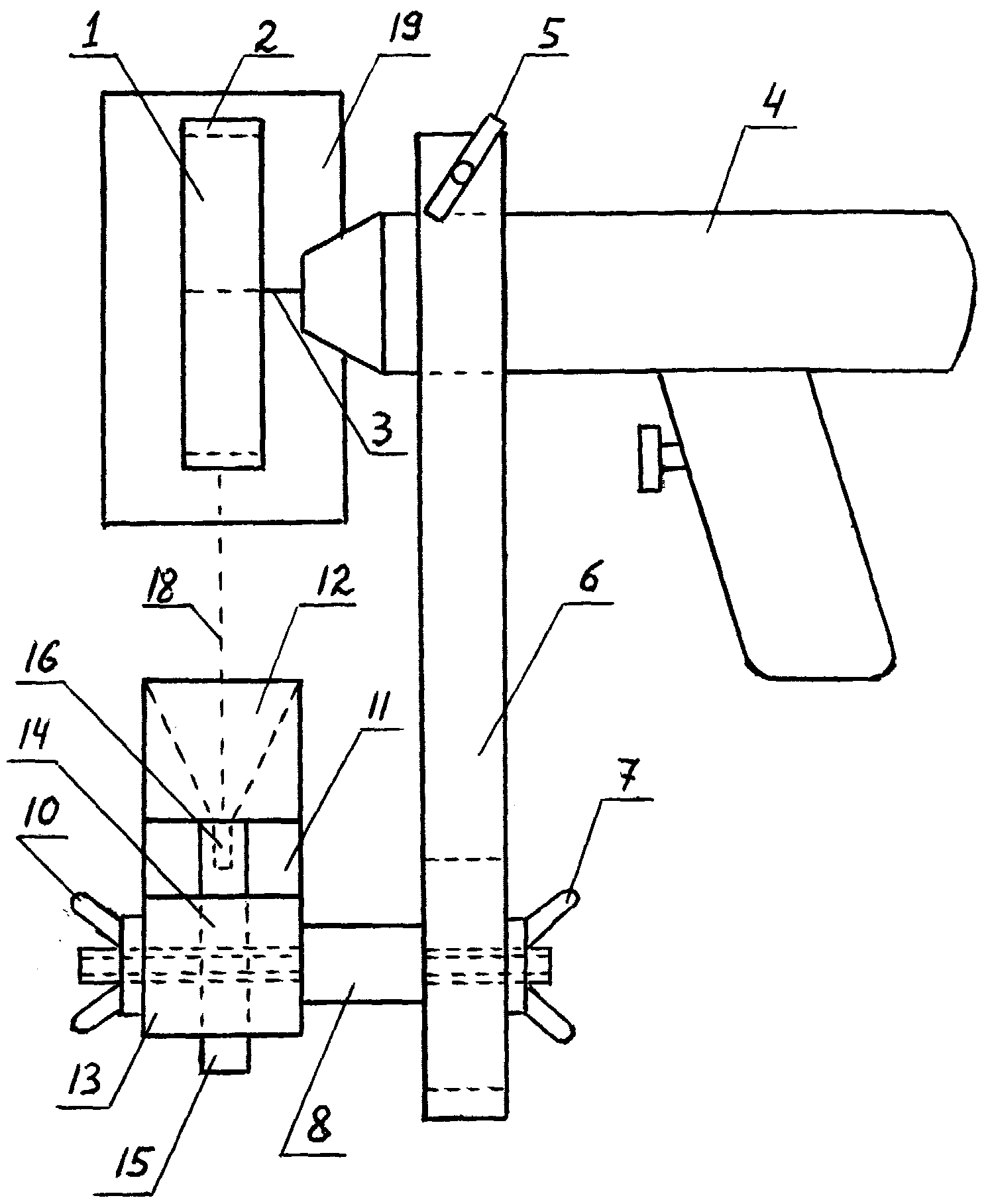
На Фиг.1 представлен главный вид пробоотборника с дисковой фрезой.Figure 1 presents the main view of the sampler with a disk cutter.
На Фиг.2 представлен вид слева пробоотборника с дисковой фрезой.Figure 2 presents the left side view of the sampler with a disk cutter.
Осуществление полезной моделиUtility Model Implementation
Пробоотборник представленный на Фиг.1 и 2 включает дисковую фрезу 1 с мелкими зубьями 2, закрепленную на оси 3, зажатой в патрон ручной дрели 4. Дрель 4 имеет автономное аккумуляторное питание. На корпусе этой же дрели при помощи винта 5 зажимается одним концом основание 6, на другом конце которого гайкой 7 зажимается несущая ось 8. Эта ось может переставляться вдоль основания 6 в пределах прорези 9. На несущей оси 8 гайкой 10 зажимается деталь 11, состоящая из выполненного в виде конусообразной воронки пробоприемника 12 с выходным отверстием на нижнем конце и зажимного устройства 13 с отверстием 14, в которое вставляется электрод 15 с кратером 16 и зажимается винтом 17. Отверстие 14 расположено так, чтобы кратер 16 электрода 15 мог быть совмещен с выходным отверстием на нижнем конце конусообразной воронки. Деталь 11 имеет возможность быть повернутой относительно несущей оси 8 с последующей фиксацией при помощи гайки 10. Перемещение несущей оси 8 в пределах прорези 9 и поворот детали 11 относительно этой оси дают возможность установления широкого входного конца пробоприемника 12 на траектории 18 движения опилок.The sampler shown in figures 1 and 2 includes a disk mill 1 with small teeth 2, mounted on an axis 3, clamped in the cartridge of a hand drill 4. The drill 4 has an autonomous battery power. On the casing of the same drill, with the help of a screw 5, the base 6 is clamped at one end, on the other end of which the bearing axis 8 is clamped with a nut 7. This axis can be rearranged along the base 6 within the slot 9. On the bearing axis 8, a nut 11 is clamped with a nut 10 a sampler 12 made in the form of a cone-shaped funnel with an outlet at the lower end and a clamping device 13 with an opening 14 into which the electrode 15 with the crater 16 is inserted and clamped by a screw 17. The hole 14 is located so that the crater 16 of the electrode 15 can be aligned with an outlet at the lower end of the cone-shaped funnel. Part 11 has the ability to be rotated relative to the bearing axis 8 with subsequent fixing with the nut 10. Moving the bearing axis 8 within the slot 9 and rotating the part 11 relative to this axis make it possible to establish a wide input end of the sample receptor 12 on the sawdust path 18.
При проведении пробоотбора оператор берет в руки дрель 4, включает вращение дисковой фрезы и с нажимом касается вращающимися зубьями 2 поверхности исследуемого образца 19. Вылетающие с места касания опилки попадают в пробоприемник 12 и направляются в кратер 16 электрода 15. Процесс идет до полного заполнения кратера. Длительность процесса пробоотбора зависит от твердости материала исследуемого образца, размеров кратера электрода и мощности дрели.When conducting a sampling, the operator picks up a drill 4, turns on the disk cutter and presses the surfaces of the test specimen 19 with the rotary teeth 2. The sawdust flying out from the place of contact enters the probe 12 and goes to the crater 16 of the electrode 15. The process continues until the crater is completely filled. The duration of the sampling process depends on the hardness of the material of the test sample, the size of the electrode crater and the power of the drill.
В пробоотборнике вставляются угольные электроды диаметром 6 мм. Размеры кратера составляют 3 мм в диаметре и 5 мм в глубину. Время пробоотбора составляет для алюминиевых и медных образцов 5-10 секунд, для стальных образцов 20-30 сек. Для исключения попадания посторонних загрязнений в пробы для разных основ сплавов используются разные сменные дисковые фрезы.In the sampler, carbon electrodes with a diameter of 6 mm are inserted. The dimensions of the crater are 3 mm in diameter and 5 mm in depth. The sampling time for aluminum and copper samples is 5-10 seconds, for steel samples 20-30 seconds. To prevent the ingress of extraneous contaminants into the samples for different alloy bases, different interchangeable disk cutters are used.
После проведения пробоотбора отжимается гайка 17, заполненный пробой электрод 15 вынимается из зажимного устройства 13 и помещается в специальный электрододержатель, служащий для транспортировки электродов с взятой пробой в кратере от места пробоотбора к месту анализа, обеспечивающий плотное закрытие входного отверстия кратера 16 и исключающий возможность высыпания опилок при транспортировке электрода от места пробоотбора к месту анализа.After the sampling, the nut 17 is squeezed out, the filled electrode 15 is removed from the clamping device 13 and placed in a special electrode holder, which serves to transport the electrodes with the sample taken in the crater from the sampling point to the place of analysis, ensuring tight closure of the inlet of the crater 16 and eliminating the possibility of sawdust spilling out when transporting the electrode from the place of sampling to the place of analysis.
Claims (4)
Priority Applications (1)
| Application Number | Priority Date | Filing Date | Title |
|---|---|---|---|
| RU2004127043/22U RU42657U1 (en) | 2004-09-09 | 2004-09-09 | SAMPLING DEVICE FOR EMISSION SPECTRAL ANALYSIS (OPTIONS) |
Applications Claiming Priority (1)
| Application Number | Priority Date | Filing Date | Title |
|---|---|---|---|
| RU2004127043/22U RU42657U1 (en) | 2004-09-09 | 2004-09-09 | SAMPLING DEVICE FOR EMISSION SPECTRAL ANALYSIS (OPTIONS) |
Publications (1)
| Publication Number | Publication Date |
|---|---|
| RU42657U1 true RU42657U1 (en) | 2004-12-10 |
Family
ID=48232250
Family Applications (1)
| Application Number | Title | Priority Date | Filing Date |
|---|---|---|---|
| RU2004127043/22U RU42657U1 (en) | 2004-09-09 | 2004-09-09 | SAMPLING DEVICE FOR EMISSION SPECTRAL ANALYSIS (OPTIONS) |
Country Status (1)
| Country | Link |
|---|---|
| RU (1) | RU42657U1 (en) |
-
2004
- 2004-09-09 RU RU2004127043/22U patent/RU42657U1/en not_active IP Right Cessation
Similar Documents
| Publication | Publication Date | Title |
|---|---|---|
| US6087183A (en) | High-throughput liquid-absorption air-sampling apparatus and methods | |
| CN103411930B (en) | Laser-induced breakdown spectrometry continuous detection device and method for heavy metal of water body | |
| JP4608370B2 (en) | Micromill for sampling | |
| CN102507894A (en) | Method for determining hydrogen content in titanium and titanium alloy | |
| CN111879548A (en) | Quick pencil terminal cross-section detection and analysis device | |
| RU42657U1 (en) | SAMPLING DEVICE FOR EMISSION SPECTRAL ANALYSIS (OPTIONS) | |
| CN104483156B (en) | A kind of acquisition methods and device of concrete deterioration detection layering sample | |
| CN204330444U (en) | A kind of concrete deterioration detects the acquisition device of layering sample | |
| CN111766243A (en) | Full-automatic wire harness terminal cross section detection and analysis device | |
| CN114878617A (en) | Method and device for enrichment and detection of trace heavy metal elements in liquid | |
| CN210090252U (en) | Atmosphere particulate matter contains lead and isotope detecting system thereof | |
| CN112161969A (en) | Method and system for detecting content of metal ions in different forms | |
| JPWO2014050786A1 (en) | Component analysis apparatus and component analysis method | |
| JP4108013B2 (en) | Hardened concrete survey method | |
| Piorek | Modern, PC based, high resolution portable EDXRF analyzer offers laboratory performance for field, in-situ analysis of environmental contaminants | |
| CN205703249U (en) | Laboratory is compound to be cut, punching sample all-in-one | |
| CN212526813U (en) | Automobile brake pad sampling machine | |
| CN114199990B (en) | Equipment and method for measuring impurity content of elements of ultra-high purity graphite material | |
| CN211602472U (en) | An ultra-low carbon steel chemical composition sampling device | |
| CN218584467U (en) | A Portable Instrument for Detecting Pigment Components on the Surface of Murals | |
| CN204286842U (en) | A kind of concrete deterioration detects the acquisition device of layering sample | |
| CN113702255A (en) | Inhalable particulate matter PM10 sailing monitor | |
| CN112198149B (en) | Portable LIBS component analyzer | |
| CN121048999B (en) | Ore sample sampling preparation device for gold ore analysis | |
| CN108332994B (en) | Precise powder taking device for anti-doping concrete |
Legal Events
| Date | Code | Title | Description |
|---|---|---|---|
| MM1K | Utility model has become invalid (non-payment of fees) |
Effective date: 20090910 |