RU36679U1 - MEANS FOR CONNECTING BETWEEN PANELS LOCATED IN ONE PLANE - Google Patents
MEANS FOR CONNECTING BETWEEN PANELS LOCATED IN ONE PLANE Download PDFInfo
- Publication number
- RU36679U1 RU36679U1 RU2003133839/20U RU2003133839U RU36679U1 RU 36679 U1 RU36679 U1 RU 36679U1 RU 2003133839/20 U RU2003133839/20 U RU 2003133839/20U RU 2003133839 U RU2003133839 U RU 2003133839U RU 36679 U1 RU36679 U1 RU 36679U1
- Authority
- RU
- Russia
- Prior art keywords
- profile
- groove
- lining
- side walls
- plane
- Prior art date
Links
Landscapes
- Finishing Walls (AREA)
Description
Средство для соединения между собой панелей, расположенных в одной плоскости.Means for interconnecting panels located in the same plane.
Полезная модель относится к средствам соединения строительных элементов в форме ллит друг с другом, в частности к профилям для соединения между собой ланелей в одной плоскости.The utility model relates to means for connecting building elements in the form of casts with each other, in particular to profiles for connecting lanels in the same plane.
Для создания ровной стеновой поверхности внутри помещения стены штукатурили по драни или обивали листами сухой штукатурки (Краткая энциклопедия домашнего хозяйства. Государственное научное издательство Советская энциклопедия. Москва, 1960г, т.2, с.436 ). Наиболее плотного лримыкания ланелей друг к другу добивались тщательным проконопачиванием щелей между ланелями. Процесс создания такой стеновой поверхности трудоемок, а соединение панелей проконопачиванием щелей не обеслечивает требуемого внешнего вида стеновой поверхности.To create a flat wall surface inside the room, the walls were plastered over or tidy with sheets of dry plaster (Brief Encyclopedia of Household. State Scientific Publishing House Soviet Encyclopedia. Moscow, 1960, v.2, p.436). The most dense sticking of the lanels to each other was achieved by thoroughly digging the cracks between the lanels. The process of creating such a wall surface is time-consuming, and the connection of the panels by prokonopachivaniem cracks does not obstruct the desired appearance of the wall surface.
Наиболее близким техническим решением к заявляемой полезной модели является средство для соединения панелей, состоящее изТ-Гобразного алюминиевого профиля и П-образного профиля, предназначенного для размещения в пазу IJTобразного профиля (Каталог чертежных и стандартных алюминиевых профилей. Профиль №98086, лрофиль № 201243. //ГАЗПРОМ АГРИСОВГАЗ. 2002г. П.5). Для того чтобы соединить две панели, размещаемые в одной плоскости, их устанавливают на направляющие каркаса стены с зазором относительно друг друга и в зазор вставляют выступ 1 Г-образного профиля, причем его полочки - отгибы располагаются на фронтальных плоскостях ланелей. Далее закрелляют профиль на каркасе той стены, на которой размещают панели. Это осуществляют с помощью крепежного элемента, устанавливаемого внутри пазаЪРобразного профиля, причем в основании паза профиля имеется выемка для центрирования крепежного элемента. Затем устанавливается П-образный профиль в паз ЪГ- образного профиля для того чтобы скрыть места крепления ТГ- образного лрофиля. П-образный лрофиль имеет выступы с внешней стороны в местах соединения основания с боковыми стенками для лозиционирования при сборке на полочках-отгибах TJ -образного профиля, а также внизу на боковых стенках для надежной фиксации в na3y1.J o6pa3Horo лрофиля.The closest technical solution to the claimed utility model is a tool for connecting panels consisting of a T-shaped aluminum profile and a U-shaped profile designed to be placed in an IJT-shaped groove (Catalog of drawing and standard aluminum profiles. Profile No. 98086, profile No. 201243. / / GAZPROM AGRISOVGAZ. 2002. P. 5). In order to connect two panels placed in one plane, they are installed on the wall frame guides with a gap relative to each other and a protrusion of 1 L-shaped profile is inserted into the gap, and its shelves - bends are located on the frontal planes of the lanels. Next, they profile the profile on the frame of the wall on which the panels are placed. This is carried out using a fastener installed inside the groove profile, and in the base of the groove of the profile there is a recess for centering the fastener. Then a U-shaped profile is installed in the groove of the b-shaped profile in order to hide the attachment points of the T-shaped profile. The U-shaped lofil has protrusions on the outside at the junction of the base with the side walls for positioning when assembling on the TJ-shaped profile bends, as well as at the bottom on the side walls for reliable fixation in the na3y1.J o6pa3Horo lofil.
Профиль П-образной формы, вылолняющий в средстве функцию накладки, скрывающей места крелления Цнэбразного лрофиля выполнен такимThe profile of the U-shaped form, fulfilling the function of an overlay in the tool, which hides the points of torsion of the Tsnebrazny lofil, is made as follows
МПК Е04В1/61 IPC E04V1 / 61
образом, что его боковые стенки жестко соединены с основанием. При допустимых отклонениях габаритных размеров П-образного профиля от номинальных значенийего размещение в Ц -образном профиле может быть затруднено. (П- образный профиль либо не фиксируется в пазу ILT-образного профиля, либо не вставляется в него). Кроме того, соотношение размеров глубины паза LJ -образного профиля и высоты стенок П-образного профиля таково, что выбор крепежных элементов по размеру строго ограничен. А также данная конструкция не обеспечивает при размещении П-образного профиля в пазу t-T -образного профиля единой плоскости, параллельной плоскости соединяемых панелей, т.е. П-образный профиль выступает из паза Т-Робразного профиля. Таким образом, такое средство для соединения между собой панелей расположенных в одной плоскости не может обеспечивать надежное соединение профилей между собой, образует ступенчатый рельеф при соединении профилей и, кроме того, ограничивает установщика панелей в подборе крепежных элементов.so that its side walls are rigidly connected to the base. With allowable deviations in the overall dimensions of the U-shaped profile from the nominal value, its placement in the C-shaped profile can be difficult. (The U-shaped profile is either not fixed in the groove of the ILT-shaped profile or is not inserted into it). In addition, the ratio of the dimensions of the groove depth of the LJ-shaped profile and the height of the walls of the U-shaped profile is such that the choice of fasteners in size is strictly limited. And also this design does not provide when placing the U-shaped profile in the groove of the t-T-shaped profile of a single plane parallel to the plane of the connected panels, i.e. The U-shaped profile protrudes from the groove of the T-shaped profile. Thus, such a means for connecting panels located in the same plane between each other cannot provide a reliable connection of the profiles to each other, forms a stepped relief when connecting profiles and, in addition, limits the panel installer in the selection of fasteners.
Задачей заявляемой полезной модели является создание средства соединения между собой панелей, расположенных в одной плоскости, обеспечивающего технический результат, заключающийся в повышении надежности фиксации профиля - накладки вТ-Г.-образном профиле, в улучшении внешнего вида средства после соединения профилей, а также в обеспечении более широкого выбора крепежных элементов.The objective of the claimed utility model is the creation of means for connecting panels located in the same plane, providing a technical result, which consists in increasing the reliability of fixing the profile - lining a VT-G.-shaped profile, in improving the appearance of the tool after connecting the profiles, as well as in ensuring a wider selection of fasteners.
Сущность заявляемой полезной модели заключается в том, что в средстве для соединения между собой панелей, расположенных в одной плоскости, содержащем профиль, имеющий ЪРобразное поперечное сечение и размещаемую в его пазу профильную накладку, имеющую П-образное поперечное сечение, основание которой при соединении с боковыми стенками образует выступы с внешней стороны профильной накладки, боковые стенки профильной накладки имеют выступы на внешней поверхности снизу, а паз профиля позволяет размещать в нем профильную накладку с обеспечением зоны для расположения крепежного элемента, при размещении профильной накладки в пазу профиля основание профильной накладки, образует одну плоскость с полочками-отгибами профиля, боковые стенки профильной накладки в местах соединения с основанием с внутренней стороны имеют утоньшения, выполненные в виде продольных канавок, а разница между величиной высоты боковых стенок профильной накладки и величиной глубины паза профиля равна или больше 1,5 мм.The essence of the claimed utility model lies in the fact that in the means for connecting panels located in the same plane, containing a profile having a b-shaped cross section and a profile plate placed in its groove having a U-shaped cross section, the base of which when connected to the side it forms protrusions on the outer side of the profile overlay, the side walls of the profile overlay have protrusions on the outer surface from the bottom, and the groove of the profile allows you to place the profile overlay in it with the zone for the location of the fastener, when placing the profile lining in the groove of the profile, the base of the profile lining forms one plane with the shelves-bends of the profile, the side walls of the profile lining at the junction with the base on the inside have thinning made in the form of longitudinal grooves, and between the height of the side walls of the profile overlay and the depth of the profile groove is equal to or greater than 1.5 mm.
боковыми стенками различны и экспериментально подобраны так, что при установке профильной накладки в паз профиля, ее основание и полочки-отгибы профиля образует одну плоскость.the side walls are different and experimentally selected so that when installing the profile lining in the groove of the profile, its base and the shelf-bends of the profile form one plane.
Боковые стенки профильной накладки в местах соединения с основанием с внутренней стороны, имеют утоньшения, выполненные в виде продольных канавок, которые могут иметь в сечении, например, форму дуги окружности, причем глубина канавки а составляет 0,4к, где к - толщина стенки профильной накладки. Выполнение таких канавок в месте соединения боковых стенок с основанием позволяет обеспечивать эффеюг подпружинивания стенок, который при сборке средства для соединения панелей, обеспечивает надежную фиксацию профильной накладки в пазу профиля при допустимых отклонениях от номинальных посадочных размеров накладки и профиля. Соотношение а 0,4к, где а - глубина канавки, к - толщина профильной накладки, объясняется тем, что именно такое утоньшение стенки обеспечивает необходимое и достаточное ее отклонение от вертикали при установке профильной накладки в паз, но не позволяет деформироваться стенке при этом отклонении.The side walls of the profile lining at the junction with the base on the inside, have thinning made in the form of longitudinal grooves, which may have, for example, a circular arc in cross section, and the depth of the groove a is 0.4 k, where k is the wall thickness of the profile lining . The implementation of such grooves at the junction of the side walls with the base allows the wall springing effect to be provided, which, when assembling the means for connecting the panels, provides reliable fixation of the profile lining in the profile groove with allowable deviations from the nominal mounting dimensions of the lining and profile. The ratio a 0.4k, where a is the depth of the groove, k is the thickness of the profile lining, is explained by the fact that it is such a thinning of the wall that provides its necessary and sufficient deviation from the vertical when the profile lining is installed in the groove, but does not allow the wall to deform with this deviation.
Разница между величиной высоты боковых стенок профильной накладки и величиной глубины паза профиля составляет величину равную или большую 1,5 мм. Это позволяет использовать большинство из существующих крепежных элементов, предназначенных для соединения двух металлических деталей, например данного / -образного профиля с каркасом стены.The difference between the height of the side walls of the profile lining and the depth of the profile groove is equal to or greater than 1.5 mm. This allows you to use most of the existing fasteners designed to connect two metal parts, for example this / -shaped profile with the frame of the wall.
Следует отметить, что такое средство обеспечивает лучший внешний вид, так как профиль и накладка при соединении образуют одну плоскость, как за счет геометрических форм в местах соединения профилей между собой, так и за счет установки профильной накладки с лодпружиниванием, что исключает перекосы и выступания накладки относительно паза профиля.It should be noted that such a tool provides a better appearance, since the profile and the cover when connecting form one plane, both due to the geometrical shapes at the points of connection of the profiles with each other, and due to the installation of the profile plate with boat springing, which eliminates distortions and protrusions of the plate relative to the profile groove.
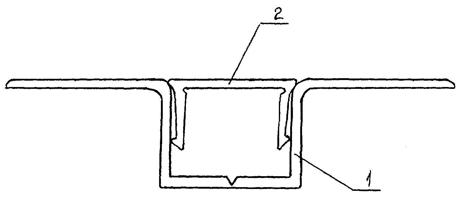
Полезная модель поясняется следующими чертежами: Фиг.1 - Средство для соединения панелей в одной плоскости в сборке. Фиг.2 - Профильная накладка. Фиг.З - Профиль 1 Г-образного сечения.The utility model is illustrated by the following drawings: Figure 1 - Means for connecting panels in one plane in the assembly. Figure 2 - Profile pad. Fig.Z - Profile 1 L-shaped section.
Средство для соединения панелей в одной плоскости содержит (см. фиг.1) профиль 1 LT-образного сечения .и профильную накладку 2 П-образного сечения. Профильная накладка 2 (см. фиг. 2) имеет основание 3 и две параллельные друг другу боковые стенки 4. В местах соединения боковых стенок 4 профильной накладки 2 с основанием 3 выполнены продольные канавки 5, например имеющие в сеченииThe means for connecting the panels in one plane contains (see FIG. 1) a profile 1 of an LT-shaped section. And a profile patch 2 of a U-shaped section. Profile plate 2 (see Fig. 2) has a base 3 and two side walls parallel to each other 4. At the junctions of the side walls 4 of the profile plate 2 with the base 3, longitudinal grooves 5 are made, for example, having a section
дугу окружности. Основание 3 при соединении с боковыми стенками 4 образует выступы 6 с внешней стороны профильной накпадки, а боковые стенки 4 профильной накладки имеют выступы 7 на внешней поверхности снизу.an arc of a circle. When connected to the side walls 4, the base 3 forms protrusions 6 on the outside of the profile cover, and the side walls 4 of the profile cover have protrusions 7 on the outer surface from the bottom.
Профиль 1 имеет (см. фиг.З) основание 8 с выемкой 9 в нем для установки крепежного злемента и две параллельные боковые стенки 10 с полочками-отгибами 11, угол отгиба которых составляет 90.Profile 1 has (see FIG. 3) a base 8 with a recess 9 in it for mounting the fastening element and two parallel side walls 10 with shelves-bends 11, the bending angle of which is 90.
Профиль 1 и профильная накладка 2 выполнены из аллюминевого сплава АД 31.Profile 1 and profile pad 2 are made of aluminum alloy AD 31.
Средство для соединения панелей в одной плоскости устанавливается следующим образом. Две панели, предназначенные для соединения, раздвигают относительно их вертикальных торцов, устанавливают между ними выступ профиля 1, прижимая к фронтальной плоскости панелей полочки-отгибы 11. Далее с помощью крепежных элементов, с использованием выемки 9 в основании 8 профиля 1, закрепляют профиль 1 на каркасе стены, на которую устанавливаются панели. Затем в паз профиля 1 помещают профильную накладку 2 слегка сжимая ее боковые стенки 4. Они, за счет утоньшений в виде продольных канавок 5, при нажиме слегка отклоняются внутрь паза профиля 1, обеспечивая легкость установки накладки 2 внутри паза надежно фиксируя накладку 2 в пазу профиля 1. Выступы 6 накладки 2 с внешней стороны в местах соединения основания 3 с боковыми стенками 4 обеспечивают позиционирование накладки 2 на полочках-отгибах 11 профиля, а выступы 7 внизу на боковых стенках 4 обеспечивают фиксацию в пазу профиля 1. При этом накладка 2 располагается в пазу профиля 1 таким образом, что ее основание 3 с. полочками-отгибами 11 профиля образует одну плоскость.Means for connecting the panels in one plane is installed as follows. Two panels intended for connection are pushed apart relative to their vertical ends, a profile 1 protrusion is installed between them, pressing the bending shelves 11 against the front plane of the panels. Next, using fasteners, using a recess 9 in the base 8 of profile 1, fix profile 1 to the frame of the wall on which the panels are installed. Then, in the groove of the profile 1, the profile overlay 2 is placed slightly compressing its side walls 4. They, due to thinning in the form of longitudinal grooves 5, slightly deflect the inside of the groove in the profile 1 when pressed, making it easy to install the overlay 2 inside the groove and securely fix the overlay 2 into the groove of the profile 1. The tabs 6 of the lining 2 from the outside at the junction of the base 3 with the side walls 4 provide positioning of the lining 2 on the shelf bends 11 of the profile, and the protrusions 7 below on the side walls 4 provide fixation in the groove of the profile 1. At the same time, the lining 2 is located in the groove of profile 1 in such a way that its base is 3 s. shelves, bends 11 profile forms one plane.
Таким образом заявляемое средство для соединения панелей в одной плоскости повышает надежность фиксации профильной накладки в Т-Г -образном профиле, улучшает внешний вид средства после соединения накладки с профилем, а также обеспечивает возможность более широкого выбора крепежных элементов для крепления на стеновой каркас.Thus, the inventive tool for connecting panels in one plane increases the reliability of fixing the profile lining in a T-shaped profile, improves the appearance of the tool after connecting the lining to the profile, and also allows a wider selection of fasteners for mounting on a wall frame.
Claims (3)
Priority Applications (1)
| Application Number | Priority Date | Filing Date | Title |
|---|---|---|---|
| RU2003133839/20U RU36679U1 (en) | 2003-11-18 | 2003-11-18 | MEANS FOR CONNECTING BETWEEN PANELS LOCATED IN ONE PLANE |
Applications Claiming Priority (1)
| Application Number | Priority Date | Filing Date | Title |
|---|---|---|---|
| RU2003133839/20U RU36679U1 (en) | 2003-11-18 | 2003-11-18 | MEANS FOR CONNECTING BETWEEN PANELS LOCATED IN ONE PLANE |
Publications (1)
| Publication Number | Publication Date |
|---|---|
| RU36679U1 true RU36679U1 (en) | 2004-03-20 |
Family
ID=36296922
Family Applications (1)
| Application Number | Title | Priority Date | Filing Date |
|---|---|---|---|
| RU2003133839/20U RU36679U1 (en) | 2003-11-18 | 2003-11-18 | MEANS FOR CONNECTING BETWEEN PANELS LOCATED IN ONE PLANE |
Country Status (1)
| Country | Link |
|---|---|
| RU (1) | RU36679U1 (en) |
Cited By (1)
| Publication number | Priority date | Publication date | Assignee | Title |
|---|---|---|---|---|
| RU2471932C2 (en) * | 2007-06-13 | 2013-01-10 | Дан-Пал | Modular panel elements of construction purpose |
-
2003
- 2003-11-18 RU RU2003133839/20U patent/RU36679U1/en not_active IP Right Cessation
Cited By (1)
| Publication number | Priority date | Publication date | Assignee | Title |
|---|---|---|---|---|
| RU2471932C2 (en) * | 2007-06-13 | 2013-01-10 | Дан-Пал | Modular panel elements of construction purpose |
Similar Documents
| Publication | Publication Date | Title |
|---|---|---|
| JP5702790B2 (en) | Method for facilitating mounting of metal sheet brackets and wall angles for inclined suspended ceilings | |
| KR100923558B1 (en) | Nstallation method of knockdown lightweight panel and knockdown lightweight panel | |
| JPS60246952A (en) | Exterior panel of building structure and method for shingling the same | |
| RU76362U1 (en) | BRACKET FOR FIXING A HINGED PANEL TO THE EXTERNAL WALL OF THE BUILDING | |
| CN110847534A (en) | Stone toilet wall assembly and mounting method thereof | |
| US3020988A (en) | Snap-in panel clip | |
| KR100928436B1 (en) | Installation method of knockdown lightweight panel and knockdown lightweight panel | |
| RU36679U1 (en) | MEANS FOR CONNECTING BETWEEN PANELS LOCATED IN ONE PLANE | |
| US20060090415A1 (en) | Suspended ceiling assembly | |
| RU85519U1 (en) | DEVICE FOR FIXING FACING TILES | |
| RU2713006C2 (en) | Method of hidden fastening of covering panels and fastening element for hidden fastening of covering panels | |
| CN217150878U (en) | Wall top closing-up structure | |
| RU16605U1 (en) | False Ceiling Design, BASIC, CROSS, CORNER, OUTDOOR CORNER, INTERNAL CORNER, ANGLE F-SHAPED AND STEADED CEILING PROFILES AND SUSPENSIONS (NOT OPTIONS FOR | |
| CN212405804U (en) | Stone toilet wall assembly | |
| CN211058187U (en) | Assembling structure for decorative plate | |
| KR20100067797A (en) | Nstallation method of knockdown lightweight panel and knockdown lightweight panel | |
| RU132823U1 (en) | INVISIBLE FASTENERS "ZIGZAG" FOR MOUNTING THE FACING BOARD | |
| CN217537434U (en) | Light gauge steel gypsum board off device | |
| CN216446310U (en) | Concealed frame ceiling structure | |
| CN209742197U (en) | Gypsum board furred ceiling fossil fragments subassembly | |
| CN219080839U (en) | Mounting assembly | |
| CN211691021U (en) | Special-shaped light steel keel ceiling structure | |
| CN218933690U (en) | Nail-free leveling keel assembly | |
| CN210737876U (en) | Single-curved metal roof aluminum-clad veneer system | |
| RU36677U1 (en) | VERTICAL PROFILE FOR LOCATION OF PANELS AT DIRECT ANGLE FROM FROM FROM |
Legal Events
| Date | Code | Title | Description |
|---|---|---|---|
| MM1K | Utility model has become invalid (non-payment of fees) |
Effective date: 20041119 |