RU32150U1 - COMBINED BEAM - Google Patents
COMBINED BEAM Download PDFInfo
- Publication number
- RU32150U1 RU32150U1 RU2003110150/20U RU2003110150U RU32150U1 RU 32150 U1 RU32150 U1 RU 32150U1 RU 2003110150/20 U RU2003110150/20 U RU 2003110150/20U RU 2003110150 U RU2003110150 U RU 2003110150U RU 32150 U1 RU32150 U1 RU 32150U1
- Authority
- RU
- Russia
- Prior art keywords
- metal insert
- wooden shelves
- wooden
- shelves
- metal
- Prior art date
Links
- 239000002184 metal Substances 0.000 claims description 40
- 230000003014 reinforcing effect Effects 0.000 claims description 5
- 230000002787 reinforcement Effects 0.000 claims description 4
- 238000005476 soldering Methods 0.000 claims description 2
- 238000003466 welding Methods 0.000 claims description 2
- 238000004519 manufacturing process Methods 0.000 description 4
- 230000015572 biosynthetic process Effects 0.000 description 3
- 238000010276 construction Methods 0.000 description 2
- 239000002023 wood Substances 0.000 description 2
- 229910000831 Steel Inorganic materials 0.000 description 1
- 241000256856 Vespidae Species 0.000 description 1
- 230000001154 acute effect Effects 0.000 description 1
- 239000000853 adhesive Substances 0.000 description 1
- 238000004026 adhesive bonding Methods 0.000 description 1
- 230000001070 adhesive effect Effects 0.000 description 1
- 238000010586 diagram Methods 0.000 description 1
- 238000009408 flooring Methods 0.000 description 1
- 238000009415 formwork Methods 0.000 description 1
- 239000000463 material Substances 0.000 description 1
- 239000010959 steel Substances 0.000 description 1
Landscapes
- Joining Of Building Structures In Genera (AREA)
- Rod-Shaped Construction Members (AREA)
Description
г о о 3 1 1 о 1 5 nr o o 3 1 1 o 1 5 n
М.Кл. Е04С 3/29M.C. E04C 3/29
КОМБИНИРОВАННАЯ БАЛКАCOMBINED BEAM
Полезная модель относится к строительству и может быть использована в строительных конструкциях зданий и сооружений.The utility model relates to construction and can be used in building structures of buildings and structures.
Известна клееная деревянная балка 1, включающая верхний и нижний нояса в виде пакетов клееной древесины, стенку в виде вкладышей и связи в местах размещения последних, установленные на клею в глухие отверстия. Вкладыши вьшолнены из пакета клееной древесины и расположены с заданньм переменным щагом, а связи расположены попарно по одному у каждой торцовой грани вкладышей. По одному из вариантов вкладьш1и размещены под прямым углом к поясам, а связи установлены во взаимно пересекаюпщхся направлениях под углом 40 - 45° к продольной оси балки. По другому варианту вкладыши вьшо.гшены в виде параллелограммов с острьм углом 40 - 45° к направлению слоев, а направление наклона граней вкладышей совпадает с направлением эпюры моментов, при этом связи установлены параллельно граням вкладьшхей.Known glued wooden beam 1, including the upper and lower novas in the form of packages of glued wood, the wall in the form of liners and ties in the places of the latter, mounted on the adhesive in blind holes. The liners are made from a package of glued wood and are arranged with a given variable pitch, and the links are arranged in pairs, one at each end face of the liners. According to one of the options, the inserts are placed at right angles to the belts, and the connections are established in mutually intersecting directions at an angle of 40 - 45 ° to the longitudinal axis of the beam. According to another variant, the inserts are completely canceled in the form of parallelograms with an acute angle of 40-45 ° to the direction of the layers, and the direction of inclination of the faces of the inserts coincides with the direction of the diagram of the moments, while the bonds are parallel to the faces of the inserts.
Из известных деревянных профильных балок наиболее близкой по технической сущности к предлагаемому техническому решению является известная металлодеревянная (комбинированная) балка 2, содержащая металлический сердечник в виде двутаврового профиля, заключенного в деревянные обкладки, стянутые крепежными деталями, при этом металлический сердечник двутаврового профиля выполнен из жестко соединенных друг с другом швеллеров, один из которых образует стенку, а два других полки профиля, при этом деревянные обкладки образованы вертикальными стенками, имеющими форму швеллера с отогнутыми концами полок и вутами в местах сочленения стенки и полок, и наружными постелями Т-образного сечения, соединенными между собой термосклейкой по швам, расположенным под углом от О до 60 градусов к горизонту, причем между полками профиля и обращенными к ним плоскостями наружных деревянных постелей образованы зазоры, заполненные компенсаторами.Of the known wooden profile beams closest in technical essence to the proposed technical solution is the well-known metal-wooden (combined) beam 2 containing a metal core in the form of an I-beam enclosed in wooden lining, tightened with fasteners, while the metal core of the I-beam is made of rigidly connected with each other channels, one of which forms a wall, and two other shelves of the profile, while the wooden lining is formed by vertical walls having the shape of a channel with bent ends of the shelves and flanges at the joints of the walls and shelves, and external T-shaped beds, interconnected by heat-gluing at the seams located at an angle from O to 60 degrees to the horizontal, between the profile shelves and facing to them by the planes of the outer wooden beds formed gaps filled with expansion joints.
Технический результат, заключающийся в устранении отмеченных недостатков известных технических решений, достигается в предлагаемой комбинированной балке, выполненной в виде двутавра, состоящего из деревянных полок и срединной металлической вставки, связанных между собой крепежными элементами, тем, что она содержит элементы усиления, выполненные в виде металлических полос, и крепежные металлические пластины, при этом на деревянных полках с внутренней стороны выполнены продольные пазы, срединная металлическая вставка выполнена из полосы с щириной, равной щирине пазов деревянных полок, и многократно изогнута в противоположных направлениях с образованием в продольном сечении зигзагообразной ломаной линии с повторяющимися секциями постоянной амплитуды и регулярным шагом их расположения по длине балки, упомянутая вставка закреплена в продольных пазах деревянных полок, крепежные металлические пластины установлены в отдельных секциях срединной металлической вставки и жестко закреплены на деревянных полках с их внутренней стороны посредством крепежных элементов, в средней части каждой крепежной металлической пластины выполнено резьбовое отверстие, в котором завернут крепежный нажимной болт, торец которого плотно прижат к опорной поверхности соответствующей секции срединной металлической вставки, причем элементы усиления расположены между деревянными полками вдоль балки под углом к деревянным полкам и жестко закреплены на срединной металлической вставке.The technical result, which consists in eliminating the noted drawbacks of the known technical solutions, is achieved in the proposed combined beam, made in the form of an I-beam, consisting of wooden shelves and a middle metal insert, interconnected by fasteners, in that it contains reinforcement elements made in the form of metal strips, and fixing metal plates, while longitudinal grooves are made on wooden shelves from the inside, the middle metal insert is made of flooring wasps with a width equal to the width of the grooves of the wooden shelves and repeatedly bent in opposite directions with the formation in the longitudinal section of a zigzag broken line with repeating sections of constant amplitude and a regular step of their location along the length of the beam, the insert is fixed in the longitudinal grooves of wooden shelves, mounting metal plates are installed in separate sections of the middle metal insert and are rigidly fixed to wooden shelves on their inner side by means of fasteners, in A threaded hole is made in the middle of each fastening metal plate, in which a fastening screw is screwed, the end of which is tightly pressed against the supporting surface of the corresponding section of the middle metal insert, the reinforcing elements are located between the wooden shelves along the beam at an angle to the wooden shelves and are rigidly fixed to the middle metal inset.
Технический результат достигается также двумя вариантами выполнения срединной металлической вставки:The technical result is also achieved by two options for the execution of the middle metal insert:
а) в форме меандра с прямоугольными секциями и б) в форме меандра с трапециевидными секциями.a) in the form of a meander with rectangular sections; and b) in the form of a meander with trapezoidal sections.
Кроме того, технический результат достигается двумя вариантами крепления крепежных металлических пластин на деревянных полках балки:In addition, the technical result is achieved by two options for fastening the mounting metal plates on the wooden shelves of the beam:
а) посредством сварки и б) посредством пайки.a) by welding; and b) by soldering.
Такое техническое решение позволяет получить комбинированную балку с высокими прочностными характеристиками.This technical solution allows to obtain a combined beam with high strength characteristics.
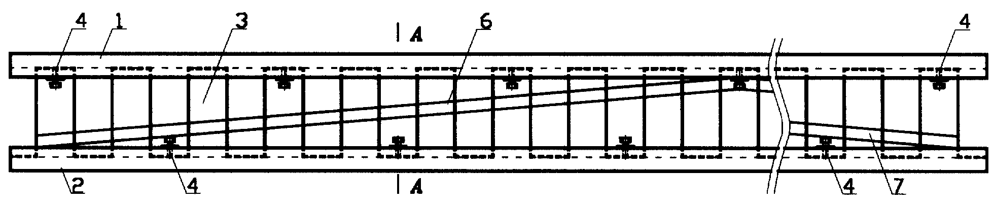
-на фигЛ показан фронтальный вид на балку;- FigL shows a front view of the beam;
-на фиг.2 нзображен вид на балку сверху;- figure 2 shows a view of the beam from above;
-на фиг.З ноказана металлическая вставка, расположенная между верхней и нижней нолками балки;-Fig. 3 shows a metal insert located between the upper and lower bars of the beam;
-на фиг.4 представлено поперечное сечение балки.- figure 4 presents the cross section of the beam.
Предлагаемая комбинированная балка (фиг. 1 - фиг. 4) выполнена в виде двутаврового профиля, состоящего из деревянных полок 1 и 2 и срединной металлической вставки 3, связанных между собой крепежными элементами 4. На деревянных полках 1 и 2 с внутренней стороны выполнены продольные пазы 5.The proposed combined beam (Fig. 1 - Fig. 4) is made in the form of an I-beam, consisting of wooden shelves 1 and 2 and a middle metal insert 3, interconnected by fasteners 4. On the wooden shelves 1 and 2, longitudinal grooves are made on the inner side 5.
Балка содержит также элементы усиления 6 и 7, выполненные в виде металлических полос, и крепежные металлические пластины 8.The beam also contains reinforcing elements 6 and 7, made in the form of metal strips, and mounting metal plates 8.
Срединная металлическая вставка 3 выполнена из полосы с шириной, равной ширине пазов 5 деревянных полок, и многократно изогнута в противоположных направлениях с образованием в продольном сечении зигзагообразной ломаной линии с повторяюп имися секциями постоянной амплитуды и регулярным шагом их расположения по длине балки. Упомянутая вставка 3 закреплена в продольных пазах 5 деревянных полок 1 и 2, крепежные металлические пластины 8 установлены в отдельных секциях срединной металлической вставки 3 и жестко закреплены на деревянных полках с их внутренней стороны.The middle metal insert 3 is made of a strip with a width equal to the width of the grooves 5 of wooden shelves, and is repeatedly bent in opposite directions with the formation in a longitudinal section of a zigzag broken line with repeated sections of constant amplitude and a regular step of their location along the length of the beam. The said insert 3 is fixed in the longitudinal grooves 5 of the wooden shelves 1 and 2, the fastening metal plates 8 are installed in separate sections of the middle metal insert 3 and are rigidly fixed to the wooden shelves from their inner side.
В средней части каждой крепежной металлической пластины 8 выполнено резьбовое отверстие, в котором завернут крепежный нажимной болт 9.In the middle part of each fixing metal plate 8, a threaded hole is made in which the fixing pressure bolt 9 is screwed.
Крепежные металлические пластины 8 закреплены на деревянных полках 1 и 2 посредством шурупов 10, ввернутых в деревянные полки.Mounting metal plates 8 are mounted on wooden shelves 1 and 2 by means of screws 10 screwed into wooden shelves.
Торец крепежного нажимного болта 9 плотно прижат к опорной поверхности 11 соответствуюш:ей секции срединной металлической вставки 3.The end face of the fixing pressure bolt 9 is tightly pressed to the supporting surface 11 correspondingly: sections of the middle metal insert 3 to it.
Элементы 6 и 7 усиления расположены между деревянньми полками 1 и 2 вдоль балки под углом к деревянным полкам и жестко закреплены на срединной металлической вставке 3.The reinforcing elements 6 and 7 are located between the wooden shelves 1 and 2 along the beam at an angle to the wooden shelves and are rigidly fixed to the median metal insert 3.
Предлагаемая комбинированная балка изготавливается и используется следующим образом.The proposed combination beam is manufactured and used as follows.
При изготовлении балки в деревянных полках 1 и 2 заданных габаритов фрезеруются продольные пазы 5 необходимой ширины и глубины.In the manufacture of beams in wooden shelves 1 and 2 of the specified dimensions, longitudinal grooves 5 of the required width and depth are milled.
Для срединной металлической вставки 3 заготавливается стальная полоса, длина которой заранее рассчитывается, а ширина равна ширине пазов 5. Затем полоса многократно изгибается в противоположных направлениях на специальном приспособлении с образованием в продольном сечении зигзагообразной ломаной линии с повторяющимися прямоугольными или трапециевидными секциями (на чертежах не показано) постоянной амплитуды и регулярным шагом их расположения по длине балки.For the middle metal insert 3, a steel strip is prepared, the length of which is calculated in advance, and the width is equal to the width of the grooves 5. Then the strip is repeatedly bent in opposite directions on a special tool with the formation in the longitudinal section of a zigzag broken line with repeating rectangular or trapezoid sections (not shown in the drawings ) constant amplitude and a regular step of their location along the length of the beam.
После этого вставка 3 закрепляется в пазах 5, а в отдельные ее секции вставляются крепежные металлические пластины 8 и закрепляются на полках 1 и 2 посредством шурупов 10.After that, the insert 3 is fixed in the grooves 5, and fixing metal plates 8 are inserted into its separate sections and fixed on the shelves 1 and 2 by means of screws 10.
В резьбовые отверстия пластин 8 вставляются болты 9 и закручиваются до упора в опорную поверхность И вставки 3.Bolts 9 are inserted into the threaded holes of the plates 8 and screwed into the bearing surface AND inserts 3 until they stop.
Затем к вставке 3 сбоку привариваются или припаиваются элементы усиления полосы 6 и 7, предназначенные для повышения жесткости конструкции балки.Then, reinforcements of the strip 6 and 7 are welded or soldered to the insert 3 on the side, designed to increase the rigidity of the beam structure.
В собранном (готовом) виде балка используется в строительных конструкциях и сооружениях по своему прямому назначению как строительная несущая деталь или для других целей, например, при изготовлении опалубки и т.п.In the assembled (finished) form, the beam is used in building structures and structures for their intended purpose as a building supporting part or for other purposes, for example, in the manufacture of formwork, etc.
Достоинством предлагаемой балки является простота ее изготовления, использование недорогих материалов и элементов, а также высокие конструкционные и строительные характеристики.The advantage of the proposed beam is the simplicity of its manufacture, the use of inexpensive materials and elements, as well as high structural and construction characteristics.
Процесс изготовления предлагаемых конструктивных изделий реализуется как на отечественном, так и импортном оборудовании с использованием стандартного и нестандартного инструмента.The manufacturing process of the proposed structural products is implemented both on domestic and imported equipment using standard and non-standard tools.
Источники информации: Sources of information:
Claims (6)
Priority Applications (1)
| Application Number | Priority Date | Filing Date | Title |
|---|---|---|---|
| RU2003110150/20U RU32150U1 (en) | 2003-04-14 | 2003-04-14 | COMBINED BEAM |
Applications Claiming Priority (1)
| Application Number | Priority Date | Filing Date | Title |
|---|---|---|---|
| RU2003110150/20U RU32150U1 (en) | 2003-04-14 | 2003-04-14 | COMBINED BEAM |
Publications (1)
| Publication Number | Publication Date |
|---|---|
| RU32150U1 true RU32150U1 (en) | 2003-09-10 |
Family
ID=35561091
Family Applications (1)
| Application Number | Title | Priority Date | Filing Date |
|---|---|---|---|
| RU2003110150/20U RU32150U1 (en) | 2003-04-14 | 2003-04-14 | COMBINED BEAM |
Country Status (1)
| Country | Link |
|---|---|
| RU (1) | RU32150U1 (en) |
-
2003
- 2003-04-14 RU RU2003110150/20U patent/RU32150U1/en not_active IP Right Cessation
Similar Documents
| Publication | Publication Date | Title |
|---|---|---|
| JP3749825B2 (en) | Brick masonry structure, brick masonry construction method and brick | |
| JP6368787B2 (en) | Three-dimensional lightweight steel frame formed by bidirectional continuous double beams | |
| KR100626542B1 (en) | Composite beam structure using sheet steel beam and concrete | |
| US20020023401A1 (en) | Structural thermal framing and panel system for assembling finished or unfinished walls with multiple panel combinations for poured and nonpoured walls | |
| AU2017203291A1 (en) | Stronger wall system | |
| US20060185291A1 (en) | Thermal Insulated Building Element | |
| EP0096118B1 (en) | Building | |
| WO1988005484A1 (en) | Frame-work for structural walls in multy-storey buildings | |
| CN108571169B (en) | Construction method for factory prefabricated steel concrete superposed shear wall assembly type building | |
| CN110366625A (en) | Wood composite device and method for manufacturing said device | |
| TW588138B (en) | Wall panel | |
| US3797183A (en) | Bearing walls and connecting members therefor | |
| US4865894A (en) | Laminar wall panel | |
| RU32150U1 (en) | COMBINED BEAM | |
| JP3208530B2 (en) | Precast concrete formwork and structure using the same | |
| CN210976073U (en) | Steel tube bundle combined shear wall and steel beam connecting node | |
| RU32806U1 (en) | COMBINED BEAM | |
| WO2010098254A1 (en) | Building unit structural member and floor structure utilizing said unit structural member | |
| JP3388093B2 (en) | Wall plate joint structure | |
| RU2358068C1 (en) | Joint connection of crossing rods | |
| EP2344703B1 (en) | Stud frame | |
| EP0687780A1 (en) | Structural sheeting | |
| JP3758173B2 (en) | A steel foundation material for buildings and a method for forming a concrete foundation for buildings using the steel foundation material. | |
| US3313070A (en) | Composite structural pillar and rafter beams with nailing strips | |
| KR101436969B1 (en) | Prefabricated wall frame using a timber |
Legal Events
| Date | Code | Title | Description |
|---|---|---|---|
| MM1K | Utility model has become invalid (non-payment of fees) |
Effective date: 20040415 |