RU2828373C1 - Method for monitoring technical state of receiving channels of receiving-transmitting modules of active phased antenna array - Google Patents
Method for monitoring technical state of receiving channels of receiving-transmitting modules of active phased antenna array Download PDFInfo
- Publication number
- RU2828373C1 RU2828373C1 RU2024106152A RU2024106152A RU2828373C1 RU 2828373 C1 RU2828373 C1 RU 2828373C1 RU 2024106152 A RU2024106152 A RU 2024106152A RU 2024106152 A RU2024106152 A RU 2024106152A RU 2828373 C1 RU2828373 C1 RU 2828373C1
- Authority
- RU
- Russia
- Prior art keywords
- receiving
- apaa
- channel
- channels
- signal
- Prior art date
Links
- 238000012544 monitoring process Methods 0.000 title claims abstract description 22
- 238000000034 method Methods 0.000 title claims description 17
- 238000012360 testing method Methods 0.000 claims abstract description 65
- 230000001427 coherent effect Effects 0.000 claims abstract description 9
- 238000006243 chemical reaction Methods 0.000 claims description 4
- 238000003491 array Methods 0.000 abstract description 3
- 230000000694 effects Effects 0.000 abstract 1
- 239000000126 substance Substances 0.000 abstract 1
- 238000009826 distribution Methods 0.000 description 8
- 238000012545 processing Methods 0.000 description 8
- 238000001208 nuclear magnetic resonance pulse sequence Methods 0.000 description 4
- 238000012937 correction Methods 0.000 description 3
- 238000004519 manufacturing process Methods 0.000 description 3
- 230000005855 radiation Effects 0.000 description 3
- 238000009825 accumulation Methods 0.000 description 2
- 230000003321 amplification Effects 0.000 description 2
- 230000006866 deterioration Effects 0.000 description 2
- 238000010586 diagram Methods 0.000 description 2
- 238000005516 engineering process Methods 0.000 description 2
- 238000003199 nucleic acid amplification method Methods 0.000 description 2
- 101000962156 Homo sapiens N-acetylglucosamine-1-phosphodiester alpha-N-acetylglucosaminidase Proteins 0.000 description 1
- 102100039267 N-acetylglucosamine-1-phosphodiester alpha-N-acetylglucosaminidase Human genes 0.000 description 1
- 230000032683 aging Effects 0.000 description 1
- 230000015572 biosynthetic process Effects 0.000 description 1
- 230000007123 defense Effects 0.000 description 1
- 238000013461 design Methods 0.000 description 1
- 230000006870 function Effects 0.000 description 1
- 238000009434 installation Methods 0.000 description 1
- 230000007257 malfunction Effects 0.000 description 1
- 230000010363 phase shift Effects 0.000 description 1
- 230000002277 temperature effect Effects 0.000 description 1
Images
Abstract
Description
Изобретение относится к радиолокационной технике и может быть использовано для контроля технического состояния приемных каналов (ПК) приемно-передающих модулей (ППМ) активных фазированных антенных решеток (АФАР), обеспечивающих формирование диаграммы направленности заданной формы, изменяемой в пространстве электронным путем.The invention relates to radar technology and can be used to monitor the technical condition of receiving channels (RC) of receiving and transmitting modules (RTM) of active phased antenna arrays (APAA), which ensure the formation of a directional pattern of a given shape, which is changed in space electronically.
В настоящее время широко используются АФАР, узлы и элементы которых имеют отклонения параметров от номинального значения, вызванные погрешностями при изготовлении, температурными воздействиями, старением или выходом из строя. В результате амплитуды и фазы сигналов на выходах разных каналов многоканальной системы будут отличаться от расчетных значений. Это вызывает ошибки в амплитудно-фазовом распределении вдоль апертуры АФАР относительно расчетных величин и, в конечном счете, вызывает ухудшение таких важнейших параметров, как коэффициент направленного действия, коэффициент полезного действия АФАР, а также приводит к изменениям значения уровня боковых лепестков. Так, например, уровень боковых лепестков в зависимости от амплитудных и фазовых ошибок в каналах АФАР может возрастать на десятки дБ [1, стр. 446-447]. Для сохранения расчетных параметров АФАР в процессе эксплуатации РЛС необходимо периодически проводить автоматизированный контроль параметров многоканального приемно-передающего тракта АФАР.Currently, APAAs are widely used, the units and elements of which have deviations of parameters from the nominal value caused by manufacturing errors, temperature effects, aging or failure. As a result, the amplitudes and phases of signals at the outputs of different channels of a multichannel system will differ from the calculated values. This causes errors in the amplitude-phase distribution along the APAA aperture relative to the calculated values and, ultimately, causes deterioration of such important parameters as the directivity coefficient, the efficiency of the APAA, and also leads to changes in the value of the side lobe level. For example, the side lobe level, depending on the amplitude and phase errors in the APAA channels, can increase by tens of dB [1, pp. 446-447]. In order to maintain the calculated parameters of the APAA during radar operation, it is necessary to periodically conduct automated monitoring of the parameters of the multichannel receiving and transmitting path of the APAA.
Из уровня техники известен способ тестирования каналов фазированной антенной решетки (ФАР), реализованный в радиолокаторе с фазированной антенной решеткой и системой тестирования ее каналов [2]. В данный радиолокатор с ФАР, содержащий опорный генератор, блок управления и первичной обработки сигнала, приемник, передатчик и устройство распределения мощности, введена вынесенная антенна и три двухпозиционных переключателя, первый из которых соединен с вынесенной антенной и обеспечивает ее подключение ко второму или третьему переключателю, второй переключатель соединен с выходом передатчика и обеспечивает его подключение к первому переключателю, а третий переключатель соединен с приемником и обеспечивает его подключение к первому переключателю. Зарегистрированное блоком управления и первичной обработки сигнала текущее амплитудно-фазовое распределение сигналов в тестируемых приемных каналах сравнивают с эталонным амплитудно-фазовым распределением (хранящимся в памяти блока управления и первичной обработки сигнала). В случае отличия тестируемого распределения от эталонного в соответствующие приемные каналы вводят поправки, компенсирующие разность тестируемого и эталонных распределений. Эти поправки обеспечиваются введением дополнительных фазовых сдвигов в управляемые фазовращатели приемных каналов приемо-передающих модулей и дополнительным изменением затухания, вносимого управляемыми аттенюаторами приемных каналов приемопередающих модулей.A method for testing phased antenna array (PA) channels is known from the prior art, implemented in a radar with a phased antenna array and a system for testing its channels [2]. In this PA radar, which contains a reference generator, a control and primary signal processing unit, a receiver, a transmitter and a power distribution device, an external antenna and three two-position switches are introduced, the first of which is connected to the external antenna and ensures its connection to the second or third switch, the second switch is connected to the transmitter output and ensures its connection to the first switch, and the third switch is connected to the receiver and ensures its connection to the first switch. The current amplitude-phase distribution of signals in the tested receiving channels, recorded by the control and primary signal processing unit, is compared with the reference amplitude-phase distribution (stored in the memory of the control and primary signal processing unit). In the event of a difference between the tested distribution and the reference, corrections are introduced into the corresponding receiving channels, compensating for the difference between the tested and reference distributions. These corrections are provided by introducing additional phase shifts into the controlled phase shifters of the receiving channels of the transmitting and receiving modules and by additionally changing the attenuation introduced by the controlled attenuators of the receiving channels of the transmitting and receiving modules.
К недостаткам такого способа можно отнести использование дополнительной антенны и активных двухпозиционных переключателей, что приводит к необходимости введения функции контроля исправности каждого из переключателей. Дополнительная антенна также накладывает ограничения на объект размещения по своим габаритным размерам и требованиям к месту установки. При сравнении амплитудно-фазового распределения с эталонным значением также не принимается во внимание ухудшение параметров переключателей, что может привести к ошибкам измерения амплитудно-фазового распределения и как следствие к неправильно выбранным поправкам, вводимым в приемные каналы.The disadvantages of this method include the use of an additional antenna and active two-position switches, which leads to the need to introduce a function for monitoring the serviceability of each switch. The additional antenna also imposes restrictions on the placement object in terms of its overall dimensions and requirements for the installation site. When comparing the amplitude-phase distribution with the reference value, the deterioration of the switch parameters is also not taken into account, which can lead to errors in measuring the amplitude-phase distribution and, as a consequence, to incorrectly selected corrections introduced into the receiving channels.
Известен также способ контроля работоспособности фазированной антенной решетки [3], заключающийся в последовательном контроле работоспособности каждого канала ФАР, изменении фазы в контролируемом канале и проведении измерений параметров сигнала на выходе сумматора ФАР при облучении апертуры ФАР внешним источником излучения, расположенным в минимуме ее диаграммы направленности, обеспечиваемом противофазным суммированием сигналов неконтролируемых каналов ФАР, определении по результатам измерения параметров сигнала на выходе сумматора ФАР степени работоспособности антенной решетки. При этом измерения параметров сигнала на выходе сумматора ФАР производят путем подключения контролируемого канала ФАР к излучателю, расположенному вблизи внешнего источника излучения, а неконтролируемых каналов ФАР - к излучателям, расположенным на противоположной, затененной от поля внешнего источника излучения стороне апертуры ФАР.A method for monitoring the operability of a phased antenna array is also known [3], which consists of sequentially monitoring the operability of each phased antenna array channel, changing the phase in the monitored channel and measuring the signal parameters at the phased antenna array combiner output when the phased antenna array aperture is irradiated by an external radiation source located at the minimum of its directional pattern, provided by antiphase summation of signals from unmonitored phased antenna array channels, determining the degree of operability of the antenna array based on the results of measuring the signal parameters at the phased antenna array combiner output. In this case, the signal parameters at the phased antenna array combiner output are measured by connecting the monitored phased antenna array channel to a radiator located near the external radiation source, and the unmonitored phased antenna array channels to radiators located on the opposite side of the phased antenna array aperture, shaded from the field of the external radiation source.
К недостаткам данного способа можно отнести использование внешней относительно контролируемой ФАР антенны, размещение которой на подвижных объектах порой невозможно, а также необходимость обеспечения фиксированного уровня тестового сигнала для оценки работоспособности канала, что крайне сложно в условиях реальной эксплуатации в большом диапазоне температур и естественного дрейфа параметров источника тестового сигнала.The disadvantages of this method include the use of an external, relatively controlled phased array antenna, the placement of which on moving objects is sometimes impossible, as well as the need to provide a fixed test signal level to assess the channel's performance, which is extremely difficult in real-life operating conditions over a wide range of temperatures and natural drift of the test signal source parameters.
Основной недостаток данного изобретения, заключается в низкой достоверности определения отказавших приемных каналов АФАР. Этот недостаток частично устранен в способе контроля технического состояния приемных каналов активной фазированной антенной решетки [4], принятом в качестве прототипа. Сущность прототипа состоит в следующем.The main disadvantage of this invention is the low reliability of determining failed receiving channels of the active phased antenna array. This disadvantage is partially eliminated in the method for monitoring the technical condition of receiving channels of an active phased antenna array [4], adopted as a prototype. The essence of the prototype is as follows.
При проведении контроля исправности приемных каналов дополнительно используют пассивный делитель тестового сигнала, на вход которого в режиме автоматизированного контроля с блока управления и обработки сигналов АФАР посредством тестового канала подают тестовые импульсные последовательности на рабочей несущей частоте. После деления тестовые импульсные последовательности через излучающие элементы направляют В каждый из приемо-усилительных каналов. При этом параметры сигналов измеряют на суммарном и разностном выходах сумматора АФАР с помощью блока управления и обработки сигналов, на входы которого измеряемые сигналы подают посредством суммарного и разностного каналов соответственно. Контроль исправности выполняют в два этапа. На первом этапе проводят проверку исправности тестового канала, при этом определяют разницы амплитуд тестовых импульсов на суммарном и разностном выходах сумматора, измеренных сначала при выключенных приемо-усилительных каналах, а затем при половине включенных синфазных приемо-усилительных каналов. Полученные значения разниц амплитуд сравнивают с пороговой величиной, которую определяют эмпирически на этапе изготовления АФАР. В случае принятия решения об исправности тестового канала и с учетом исправности суммарного и разностного каналов приступают ко второму этапу проверки, на котором проверяют исправность каждого приемо-усилительного канала путем последовательного поочередного их включения и измерения амплитуд тестовых импульсов на суммарном и разностном выходах сумматора для различных значений фазовращателей приемо-передающих модулей АФАР.When testing the serviceability of the receiving channels, a passive test signal divider is additionally used, to the input of which, in the automated testing mode, test pulse sequences at the operating carrier frequency are fed from the APAA signal control and processing unit via the test channel. After dividing, the test pulse sequences are sent to each of the receiving and amplifying channels via the radiating elements. In this case, the signal parameters are measured at the sum and difference outputs of the APAA adder using the control and signal processing unit, to the inputs of which the measured signals are fed via the sum and difference channels, respectively. The serviceability testing is performed in two stages. At the first stage, the serviceability of the test channel is checked, while determining the differences in the amplitudes of the test pulses at the sum and difference outputs of the adder, measured first with the receiving and amplifying channels turned off, and then with half of the in-phase receiving and amplifying channels turned on. The obtained values of the amplitude differences are compared with the threshold value, which is determined empirically at the stage of APAA manufacturing. If a decision is made about the serviceability of the test channel and taking into account the serviceability of the sum and difference channels, they proceed to the second stage of testing, at which the serviceability of each receiving and amplifying channel is checked by sequentially switching them on in turn and measuring the amplitudes of the test pulses at the sum and difference outputs of the adder for different values of the phase shifters of the receiving and transmitting modules of the APAA.
Зарегистрированные блоком управления и обработки сигналов усредненные значения амплитуд тестовых импульсов каждого приемо-усилительного канала сравнивают между собой. При нахождении полученных значений амплитуд каждого приемо-усилительного канала в установленных границах относительно максимального опорного значения амплитуды по каждому из каналов принимают решение о его исправности, либо в противном случае - трешение о его отказе. При этом решение об исправности принимают по следующему критерию:The averaged values of the amplitudes of the test pulses of each receiving and amplifying channel, registered by the control and signal processing unit, are compared with each other. If the obtained values of the amplitudes of each receiving and amplifying channel are found to be within the established limits relative to the maximum reference value of the amplitude for each of the channels, a decision is made about its serviceability, or otherwise - a decision about its failure. In this case, the decision about serviceability is made according to the following criterion:
где U i - измеренная усредненная амплитуда сигнала на выходе i-го канала,where U i is the measured average amplitude of the signal at the output of the i -th channel,
Uоп - максимальное опорное значение амплитуды,U op - maximum reference value of the amplitude,
ΔUипк - пороговая величина для оценки исправности приемо-усилительных каналов, определяемая эмпирически.ΔU ipk is a threshold value for assessing the serviceability of the receiving and amplifying channels, determined empirically.
Дополнительно отметим, что осуществляется усреднение измеренных значений амплитуды i-го канала. В то же время основной недостаток способа-прототипа - низкая достоверность результатов контроля остается прежним. Дело в том, что контролируемый канал в штатном режиме в составе РЛС работает в одних условиях, а при контроле - в других. При работе РЛС в штатном режиме электромагнитная энергия падающей на апертуру АФАР плоской волны распределяется примерно равномерно между всеми приемо-усилительными каналами, вследствие чего отношение сигнал-шум на входе одного канала оказывается значительно меньше единицы. Требуемое значение сигнал-шум восстанавливается в результате когерентного суммирования сигналов с выходов всех приемных каналов. При этом рабочая точка малошумящего усилителя (МШУ), на вход которого поступает сигнал от i-го излучательного элемента АФАР, находится на нижнем нелинейном участке его амплитудной характеристики, форма которого обычно контролю не подвергается, а именно он определяет существенный разброс значений коэффициента усиления, и именно это обстоятельство необходимо учитывать при организации контроля исправности приемных каналов. Однако это не было сделано при разработке способа-прототипа, применение которого предполагает выполнение следующих операций.Additionally, we note that the measured values of the amplitude of the i -th channel are averaged. At the same time, the main disadvantage of the prototype method - low reliability of the testing results remains the same. The fact is that the controlled channel in the normal mode as part of the radar operates under one set of conditions, and during testing - under another. When the radar is operating in the normal mode, the electromagnetic energy of the plane wave incident on the APAA aperture is distributed approximately evenly between all the receiving and amplifying channels, as a result of which the signal-to-noise ratio at the input of one channel is significantly less than unity. The required signal-to-noise value is restored as a result of coherent summation of the signals from the outputs of all receiving channels. In this case, the operating point of the low-noise amplifier (LNA), to the input of which the signal from the i -th radiating element of the APAA is fed, is on the lower nonlinear section of its amplitude characteristic, the shape of which is usually not subject to testing, but it is this section that determines a significant spread of the gain values, and it is this circumstance that must be taken into account when organizing testing of the receiving channels for serviceability. However, this was not done when developing the prototype method, the use of which involves performing the following operations.
Для проведения контроля исправности приемных каналов АФАР используют пассивный делитель тестового сигнала. В режиме автоматизированного контроля на делитель тестового сигнала от блока управления и обработки сигналов АФАР посредством тестового канала подают тестовые импульсные последовательности на рабочей несущей частоте. После деления данные импульсные последовательности через излучающие элементы направляют в каждый из приемных каналов приемно-передающих модулей (ППМ) АФАР. Контроль исправности приемных каналов проводят в два этапа. На первом этапе проводят проверку исправности тестового канала путем сравнения с заданной пороговой величиной разницы амплитуд тестовых импульсов на выходах сумматора АФАР: измеренных при выключенных приемо-усилительных каналах и измеренных при половине включенных синфазных каналов. Используемая в данном случае пороговая величина определяется эмпирически на этапе изготовления АФАР. В случае принятия решения об исправности тестового канала приступают ко второму этапу проверки, на котором проверяют исправность каждого приемо-усилительного канала путем последовательного поочередного их включения и измерения амплитуд тестовых импульсов на суммарном и разностном выходах сумматора для различных значений фазовращателей приемо-передающих модулей АФАР. После этого зарегистрированные блоком управления и обработки сигналов усредненные значения амплитуд тестовых импульсов каждого приемо-усилительного канала сравнивают между собой и при нахождении этих значений в установленных границах относительно максимального опорного значения амплитуды по каждому из каналов принимают решение о его исправности, либо в противном случае - решение о его отказе.To check the serviceability of the APAA receiving channels, a passive test signal divider is used. In the automated testing mode, test pulse sequences at the operating carrier frequency are fed to the test signal divider from the APAA signal control and processing unit via the test channel. After dividing, these pulse sequences are sent through the emitting elements to each of the receiving channels of the APAA transmitting and receiving modules (TTM). The serviceability of the receiving channels is checked in two stages. At the first stage, the serviceability of the test channel is checked by comparing the difference in the amplitudes of the test pulses at the APAA adder outputs with a specified threshold value: measured with the receiving and amplifying channels turned off and measured with half of the in-phase channels turned on. The threshold value used in this case is determined empirically at the APAA manufacturing stage. In case of making a decision on the serviceability of the test channel, proceed to the second stage of testing, at which the serviceability of each receiving and amplifying channel is checked by successively switching them on in turn and measuring the amplitudes of the test pulses at the sum and difference outputs of the adder for different values of the phase shifters of the receiving and transmitting modules of the AFAR. After this, the averaged values of the amplitudes of the test pulses of each receiving and amplifying channel recorded by the control and signal processing unit are compared with each other and if these values are within the established limits relative to the maximum reference value of the amplitude for each of the channels, a decision is made on its serviceability, or otherwise - a decision on its failure.
Решение об исправности или отказе канала принимается независимо от уровня подаваемого тестового сигнала. Обратим внимание на последнюю фразу. Именно в этом состоит основной недостаток способа-прототипа: в штатном режиме работы на вход приемного канала поступают сигналы, уровень которых значительно ниже уровня собственных шумов канала, а результаты контроля исправности канала не зависят от уровня тестового сигнала. Очевидно, что такие результаты не могут быть признаны достоверными. Кроме того, оценка технического состояния приемных каналов ППМ АФАР осуществляется на основе последовательного сравнения амплитуд тестовых импульсов на выходе приемо-усилительного канала каждого ППМ АФАР.The decision on the channel's serviceability or failure is made regardless of the level of the supplied test signal. Let's pay attention to the last phrase. This is the main drawback of the prototype method: in the normal operating mode, signals are received at the input of the receiving channel whose level is significantly lower than the level of the channel's own noise, and the results of monitoring the channel's serviceability do not depend on the level of the test signal. Obviously, such results cannot be considered reliable. In addition, the technical condition of the receiving channels of the APAA TPM is assessed based on a sequential comparison of the amplitudes of the test pulses at the output of the receiving and amplifying channel of each APAA TPM.
В соответствии с изложенным цели предлагаемого технического решения состоят в следующем:In accordance with the above, the objectives of the proposed technical solution are as follows:
в повышении оперативности контроля технического состояния приемных каналов АФАР за счет одновременного контроля приемных каналов всех N ППМ АФАР;in increasing the efficiency of monitoring the technical condition of the APAA receiving channels due to the simultaneous monitoring of the receiving channels of all N APAA PPMs;
в обеспечении достоверности результатов контроля технического состояния приемных каналов АФАР за счет использования в качестве тестовых сигналов когерентной пачки N прямоугольных радиоимпульсов несущей частоты, мощность каждого из которых лежит в диапазоне мощностей, значительно ниже уровня собственных шумов контролируемого канала.in ensuring the reliability of the results of monitoring the technical condition of the receiving channels of the APAA by using as test signals a coherent packet of N rectangular radio pulses of the carrier frequency, the power of each of which lies in the power range significantly lower than the level of the intrinsic noise of the monitored channel.
Технический результат изобретения состоит в повышении оперативности и обеспечении достоверности результатов контроля технического состояния приемных каналов ППМ АФАР.The technical result of the invention consists in increasing the efficiency and ensuring the reliability of the results of monitoring the technical condition of the receiving channels of the AFAR PPM.
Указанные цели достигается тем, что тестовые сигналы подаются одновременно на все приемные каналы ППМ АФАР и в качестве тестовых сигналов в предлагаемом техническом решении принята когерентная пачка N прямоугольных радиоимпульсов несущей частоты, мощность каждого из которых лежит в диапазоне мощностей, значительно ниже уровня собственных шумов контролируемого канала, а длительность согласована с шириной полосы пропускания канала. Тестовый сигнал (ТС) с выхода формирователя ТС через нулевой канал пассивного делителя ТС подают на вход опорного приемного канала, дополнительно введенного в состав АФАР. Результаты контроля технического состояния приемных каналов ППМ АФАР поступают с соответствующих выходов блока сравнения на блок выдачи решения практически одновременно, а не последовательно как в способе-прототипе.The stated objectives are achieved by the fact that test signals are fed simultaneously to all receiving channels of the APAA PPM and a coherent packet of N rectangular radio pulses of carrier frequency is adopted as test signals in the proposed technical solution, the power of each of which lies in the power range significantly below the level of the intrinsic noise of the monitored channel, and the duration is matched with the bandwidth of the channel. The test signal (TS) from the output of the TS former through the zero channel of the passive TS divider is fed to the input of the reference receiving channel, additionally introduced into the APAA. The results of monitoring the technical condition of the receiving channels of the APAA PPM are received from the corresponding outputs of the comparison unit to the decision issuing unit almost simultaneously, and not sequentially as in the prototype method.
Предлагаемый способ контроля технического состояния приемных каналов приемно-передающих модулей активной фазированной антенной решетки характеризуется следующими отличительными признаками по сравнению с прототипом:The proposed method for monitoring the technical condition of the receiving channels of the receiving and transmitting modules of an active phased antenna array is characterized by the following distinctive features in comparison with the prototype:
в качестве тестовых сигналов применяют когерентную последовательность N прямоугольных радиоимпульсов несущей частоты, мощность каждого из которых имеет величину одного порядка с мощностью сигнала, поступающего на вход каждого приемного канала при работе РЛС в штатном режиме по целям, то есть значительно ниже уровня собственных шумов приемных каналов, а длительность тестового радиоимпульса согласована с шириной полосы пропускания приемного канала;a coherent sequence of N rectangular radio pulses of carrier frequency is used as test signals, the power of each of which has a value of the same order of magnitude as the power of the signal arriving at the input of each receiving channel when the radar is operating in normal mode for targets, that is, significantly lower than the level of the intrinsic noise of the receiving channels, and the duration of the test radio pulse is matched to the bandwidth of the receiving channel;
тестовый сигнал с выхода формирователя ТС через нулевой канал пассивного делителя ТС подают на вход опорного приемного канала, дополнительно введенного в состав АФАР;the test signal from the output of the TS generator through the zero channel of the passive TS divider is fed to the input of the reference receiving channel, additionally included in the AFAR;
путем усиления и когерентного накопления N тестовых радиоимпульсов формируют на выходе опорного приемного канала сигнал, отношение сигнал-шум которого в N раз выше, чем на его входе, аналогично путем усиления и когерентного накопления N усиленных тестовых радиоимпульсов формируют на выходах каждого контролируемого приемного канала сигналы, отношение сигнал-шум которых в N раз превышает аналогичное отношение на их входах, сигнал с выхода опорного приемного канала подвергают аналого-цифровому преобразованию и квадратурной демодуляции, полученный результат подают на нулевой вход блока сравнения, аналогично сигналы с выходов всех контролируемых приемных каналов подвергают аналого-цифровому преобразованию и квадратурной демодуляции, полученные результаты подают на i-e входы блока сравнения, посредством которого осуществляют одновременное сравнение квадратурных составляющих выходных сигналов всех контролируемых приемных каналов с соответствующими квадратурными составляющими выходного сигнала опорного приемного канала и в случае их равенства или расхождения в допустимых пределах, которые определяют эмпирически, принимают решение об исправном состоянии контролируемого приемных каналов, в противном случае - о неисправном.by amplifying and coherently accumulating N test radio pulses, a signal is formed at the output of the reference receiving channel whose signal-to-noise ratio is N times higher than at its input; similarly, by amplifying and coherently accumulating N amplified test radio pulses, signals are formed at the outputs of each monitored receiving channel whose signal-to-noise ratio is N times higher than the analogous ratio at their inputs; the signal from the output of the reference receiving channel is subjected to analog-to-digital conversion and quadrature demodulation; the obtained result is fed to the zero input of the comparison unit; similarly, the signals from the outputs of all monitored receiving channels are subjected to analog-to-digital conversion and quadrature demodulation; the obtained results are fed to the i -th inputs of the comparison unit, by means of which a simultaneous comparison of the quadrature components of the output signals of all monitored receiving channels is performed with the corresponding quadrature components of the output signal of the reference receiving channel and, in the event of their equality or discrepancy within the permissible limits, which are determined empirically, a decision is made on the serviceable condition of the monitored receiving channels, in Otherwise, it is faulty.
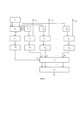
На фиг. 1 приведен вариант структурной схемы устройства, реализующего предлагаемый способ контроля технического состояния приемных каналов (ПК) ППМ АФАР, в состав которой входят N ППМ 1 i с излучателями 2 i и направленными ответвителями 3 i , где а N - количество приемных каналов ППМ АФАР, подлежащих контролю их технического состояния. Выходы всех контролируемых приемных каналов ППМ 1, подключены к соответствующим аналого-цифровым квадратурным демодуляторам (АЦКД) 4 i , выходы которых в свою очередь соединены с соответствующими входами блока 5 сравнения (БС), выходы которого в свою очередь подключены ко входам блока 6 принятия решения (БПР) о техническом состоянии каждого контролируемого ПК.Fig. 1 shows a variant of the structural diagram of the device implementing the proposed method for monitoring the technical condition of the receiving channels (RC) of the AFAR PPM, which includes N PPM 1 i with
Кроме того, в состав структурной схемы (фиг. 1) входит формирователь 7 тестового сигнала (ФТС), который по своей структуре и по форме тестового сигнала в корне отличается от соответствующих элементов прототипа, и пассивный делитель 8 тестового сигнала, что позволило подавать на входы контролируемых ПК тестовые сигналы, уровень которых соответствует уровню принимаемых сигналов при боевой работе РЛС, что и обеспечивает достоверность принимаемых решений о техническом состоянии контролируемых ПК.In addition, the structural diagram (Fig. 1) includes a test signal generator (TSG) 7, which in its structure and in the form of the test signal is fundamentally different from the corresponding elements of the prototype, and a passive
Пассивный делитель 8 тестового сигнала имеет N+1 выход (от 0 до N). Нулевой выход делителя 8 связан со входом дополнительно введенного состав АФАР опорного приемного канала 9, выход которого через соответствующий АЦКД 40 связан нулевым входом блока 5.The
В процессе контроля технического состояния ПК ППМ АФАР выполняют следующие операции.In the process of monitoring the technical condition of the PC PPM AFAR, the following operations are performed.
1. Формируют тестовый сигнал в виде когерентной последовательности N прямоугольных радиоимпульсов, где N-количество контролируемых ПК ППМ, а уровень мощности каждого радиоимпульса имеет величину одного порядка с мощностью сигнала, поступающего на вход каждого ПК при работе РЛС в штатном режиме по целям значительно ниже уровня собственных шумов ПК, а длительность радиоимпульсов согласована с шириной полосы пропускания ПК.1. A test signal is generated in the form of a coherent sequence of N rectangular radio pulses, where N is the number of controlled PCs of the PPM, and the power level of each radio pulse has a value of the same order of magnitude as the power of the signal arriving at the input of each PC when the radar is operating in normal mode for targets significantly below the PC's own noise level, and the duration of the radio pulses is matched to the PC's bandwidth.
2. Тестовые сигналы с выхода формирователя 7 ТС подают на вход пассивного делителя 8 ТС, с нулевого выхода которого ТС подают на вход опорного приемного канала 9, а со всех i-x выходов пассивного делителя 8 ТС - через соответствующие направленные ответвители 3 на входы соответствующих контролируемых приемных каналов ППМ 1.2. Test signals from the output of the
3. После усиления тестовых радиоимпульсов и когерентного накопления усиленных радиоимпульсов формируют на выходе опорного приемного канала 9 сигнал с требуемым отношением сигнал-шум, который подают на вход аналого-цифрового квадратурного демодулятора 40, посредством которого формируют квадратурные составляющие (синфазную и квадратурную) выходного сигнала опорного ПК, которые подают на Нулевой вход блока 5 сравнения.3. After amplification of the test radio pulses and coherent accumulation of the amplified radio pulses, a signal with the required signal-to-noise ratio is formed at the output of the reference receiving channel 9, which is fed to the input of the analog-to-
4. После усиления N тестовых радиоимпульсов и когерентного накопления усиленных радиоимпульсов формируют на выходе каждого контролируемого приемного канала ППМ 1 i сигнал с требуемым отношением сигнал-шум, которые подают на входы соответствующих аналого-цифровых квадратурных демодуляторов 4i, посредством которых формируют синфазные и квадратурные составляющие выходных сигналов контролируемых приемных каналов, которые подают на соответствующие входы блока 5 сравнения.4. After amplification of N test radio pulses and coherent accumulation of the amplified radio pulses, a signal with the required signal-to-noise ratio is formed at the output of each monitored receiving channel of the PPM 1 i , which is fed to the inputs of the corresponding analog-to-digital quadrature demodulators 4 i , by means of which in-phase and quadrature components of the output signals of the monitored receiving channels are formed, which are fed to the corresponding inputs of the
5. Если в результате последовательного сравнения синфазных и квадратурных составляющих выходных сигналов контролируемых приемных каналов с соответствующими составляющими выходного сигнала опорного приемного канала установлено их равенство или расхождение в допустимых пределах, определяемых эмпирически, в блоке 6 принимается решение об исправности соответствующего контролируемого приемного канала. В противном случае принимается решение о его неисправности.5. If, as a result of successive comparison of the in-phase and quadrature components of the output signals of the monitored receiving channels with the corresponding components of the output signal of the reference receiving channel, their equality or discrepancy is established within the permissible limits determined empirically, a decision is made in
Отличия предлагаемого способа контроля технического состояния приемных каналов приемно-передающих модулей активной фазированной антенной решетки от прототипа являются существенными, так как они позволяют в N раз снизить время контроля технического состояния приемных каналов АФАР и обеспечить его достоверность.The differences between the proposed method of monitoring the technical condition of the receiving channels of the receiving and transmitting modules of the active phased antenna array and the prototype are significant, since they allow for a reduction in the time of monitoring the technical condition of the receiving channels of the active phased antenna array by N times and ensure its reliability.
Источники информацииSources of information
1. Проектирование фазированных антенных решеток. Под ред. Д.И. Воскресенского. М.: Радиотехника, 2003, 632 с.1. Design of phased antenna arrays. Edited by D.I. Voskresensky. Moscow: Radio Engineering, 2003, 632 p.
2. Патент № 2562068 С1 Российская Федерация, МПК G01S 7/40. радиолокатор с фазированной антенной решеткой и системой тестирования ее каналов: № 2014110194/07: заявл. 18.03.2014, опубл. 10.09.2015 / А.И. Клименко; заявитель Закрытое акционерное общество "Аэрокосмические технологии". - EDN IFRNPA.2. Patent No. 2562068 C1 Russian Federation,
3. Авторское свидетельство № 1666979 А1 СССР, МПК G01R 29/10. Способ контроля работоспособности фазированной антенной решетки: №4124558: заявл. 11.06.1986: опубл. 30.07.1991 / В.Н. Кочешев, И.Р. Москович, А. М. Расин; заявитель ПРЕДПРИЯТИЕ П/Я Г-4421. - EDN XZNROG.3. Author's certificate No. 1666979 A1 USSR, IPC G01R 29/10. Method for testing the operability of a phased antenna array: No. 4124558: declared 11.06.1986: published 30.07.1991 / V.N. Kocheshev, I.R. Moskovich, A.M. Rasin; applicant ENTERPRISE P.O. Box G-4421. - EDN XZNROG.
4. Патент № 2697813 С1 Российская Федерация, МПК G01S 7/40. Способ контроля исправности приемо-усилительных каналов активной фазированной антенной решетки: №2018138680: заявл. 01.11.2018: опубл. 20.08.2019 / Г.А. Елисюткин, В.В. Кирьянов, Р.В. Поликашкин [и др.]; заявитель Российская Федерация, от имени которой выступает Министерство обороны Российской Федерации. - EDN AKBDZG.4. Patent No. 2697813 C1 Russian Federation,
Claims (1)
Publications (1)
| Publication Number | Publication Date |
|---|---|
| RU2828373C1 true RU2828373C1 (en) | 2024-10-10 |
Family
ID=
Citations (8)
| Publication number | Priority date | Publication date | Assignee | Title |
|---|---|---|---|---|
| RU2413345C2 (en) * | 2009-04-20 | 2011-02-27 | Открытое акционерное общество "Морской научно-исследовательский институт радиоэлектроники "Альтаир" (ОАО "МНИИРЭ "Альтаир") | Diagnostic method of state of elements of phased antenna array |
| US8013783B2 (en) * | 2007-12-31 | 2011-09-06 | Elta Systems Ltd. | Phased array antenna having integral calibration network and method for measuring calibration ratio thereof |
| RU2467346C1 (en) * | 2011-07-04 | 2012-11-20 | Федеральное государственное унитарное предприятие "Ростовский-на-Дону научно-исследовательский институт радиосвязи" (ФГУП "РНИИРС") | Method of calibrating active phased antenna array |
| RU2697813C1 (en) * | 2018-11-01 | 2019-08-20 | Российская Федерация, от имени которой выступает Министерство обороны Российской Федерации | Method for monitoring serviceability of receiving-amplification channels of an active phased antenna array |
| RU2752553C1 (en) * | 2020-12-01 | 2021-07-29 | Федеральное государственное казенное военное образовательное учреждение высшего образования "Санкт-Петербургский военный ордена Жукова институт войск национальной гвардии Российской Федерации" | Method for integrated monitoring of characteristics of digital active phased array antenna |
| CN115361075A (en) * | 2022-07-27 | 2022-11-18 | 中国船舶重工集团公司第七二四研究所 | Digital phased array transmit-receive channel online fault monitoring method |
| CN115494462A (en) * | 2022-01-26 | 2022-12-20 | 常州第四无线电厂有限公司 | Phased array radar online automatic amplitude and phase calibration method and storage medium |
| CN116381657A (en) * | 2023-06-07 | 2023-07-04 | 天津知海科技有限公司 | Transmission channel failure monitoring method, device, sonar transmitter and storage medium |
Patent Citations (8)
| Publication number | Priority date | Publication date | Assignee | Title |
|---|---|---|---|---|
| US8013783B2 (en) * | 2007-12-31 | 2011-09-06 | Elta Systems Ltd. | Phased array antenna having integral calibration network and method for measuring calibration ratio thereof |
| RU2413345C2 (en) * | 2009-04-20 | 2011-02-27 | Открытое акционерное общество "Морской научно-исследовательский институт радиоэлектроники "Альтаир" (ОАО "МНИИРЭ "Альтаир") | Diagnostic method of state of elements of phased antenna array |
| RU2467346C1 (en) * | 2011-07-04 | 2012-11-20 | Федеральное государственное унитарное предприятие "Ростовский-на-Дону научно-исследовательский институт радиосвязи" (ФГУП "РНИИРС") | Method of calibrating active phased antenna array |
| RU2697813C1 (en) * | 2018-11-01 | 2019-08-20 | Российская Федерация, от имени которой выступает Министерство обороны Российской Федерации | Method for monitoring serviceability of receiving-amplification channels of an active phased antenna array |
| RU2752553C1 (en) * | 2020-12-01 | 2021-07-29 | Федеральное государственное казенное военное образовательное учреждение высшего образования "Санкт-Петербургский военный ордена Жукова институт войск национальной гвардии Российской Федерации" | Method for integrated monitoring of characteristics of digital active phased array antenna |
| CN115494462A (en) * | 2022-01-26 | 2022-12-20 | 常州第四无线电厂有限公司 | Phased array radar online automatic amplitude and phase calibration method and storage medium |
| CN115361075A (en) * | 2022-07-27 | 2022-11-18 | 中国船舶重工集团公司第七二四研究所 | Digital phased array transmit-receive channel online fault monitoring method |
| CN116381657A (en) * | 2023-06-07 | 2023-07-04 | 天津知海科技有限公司 | Transmission channel failure monitoring method, device, sonar transmitter and storage medium |
Similar Documents
| Publication | Publication Date | Title |
|---|---|---|
| EP2476163B1 (en) | Antenna failure compensation | |
| US10819446B2 (en) | Radar transmitting power and channel performance monitoring apparatus | |
| US5867123A (en) | Phased array radio frequency (RF) built-in-test equipment (BITE) apparatus and method of operation therefor | |
| Hoffman et al. | Digital calibration of TR modules for real-time digital beamforming SweepSAR architectures | |
| EP1428043B1 (en) | Active phased array with verification of drift in the calibration network | |
| Temir et al. | Consideration of environmental and functional factors in calibration of antenna integrated active phased array transmitters | |
| US8004456B2 (en) | Antenna calibration | |
| RU2828373C1 (en) | Method for monitoring technical state of receiving channels of receiving-transmitting modules of active phased antenna array | |
| GB2259778A (en) | Testing radar antenna systems | |
| US8085189B2 (en) | Antenna calibration | |
| US20200150225A1 (en) | Determining transmission phase shifts for a radar with a plurality of juxtaposed transmission paths | |
| RU2511032C2 (en) | Method for integrated control of characteristics of active phased antenna array | |
| KR102729781B1 (en) | Active phased-array antenna apparatus and antenna pattern synthesis method using the same | |
| US8004457B2 (en) | Antenna calibration | |
| Kumar et al. | Efficacy Analysis of In-Situ Calibration of Airborne AESA | |
| EP2296223A1 (en) | Antenna failure compensation | |
| RU2697813C1 (en) | Method for monitoring serviceability of receiving-amplification channels of an active phased antenna array | |
| US7990312B2 (en) | Antenna calibration | |
| Reising et al. | Noise Figure Calculation for Space Surveillance Radar Systems | |
| RU2792222C1 (en) | Method of correction of the amplitude-phase distribution of opened antenna array | |
| Saleem et al. | Pattern compensation of a planar phased array with centre elements phase malfunctioning using a genetic algorithm | |
| RU2826839C1 (en) | Method of monitoring complex gain of receiving channel of receiving-transmitting module of active phased antenna array of microwave range | |
| RU2752553C1 (en) | Method for integrated monitoring of characteristics of digital active phased array antenna | |
| Andrews | Antenna and other systematic effects on amplitude comparison monopulse systems | |
| RU2788831C2 (en) | Determination of phase shifts of transmission for radar with set of combined transmission tracts |