RU2785373C1 - Twin power drive system and vehicle - Google Patents
Twin power drive system and vehicle Download PDFInfo
- Publication number
- RU2785373C1 RU2785373C1 RU2022117569A RU2022117569A RU2785373C1 RU 2785373 C1 RU2785373 C1 RU 2785373C1 RU 2022117569 A RU2022117569 A RU 2022117569A RU 2022117569 A RU2022117569 A RU 2022117569A RU 2785373 C1 RU2785373 C1 RU 2785373C1
- Authority
- RU
- Russia
- Prior art keywords
- oil
- power
- control
- drive system
- hydraulic motor
- Prior art date
Links
- 230000009977 dual effect Effects 0.000 claims abstract description 33
- 230000007246 mechanism Effects 0.000 claims abstract description 33
- 239000003921 oil Substances 0.000 claims description 153
- 239000010720 hydraulic oil Substances 0.000 claims description 24
- 230000005540 biological transmission Effects 0.000 claims description 21
- 238000004891 communication Methods 0.000 claims description 16
- 230000000694 effects Effects 0.000 abstract 1
- 239000000126 substance Substances 0.000 abstract 1
- 239000002689 soil Substances 0.000 description 7
- 230000005484 gravity Effects 0.000 description 4
- 230000009286 beneficial effect Effects 0.000 description 2
- 230000003749 cleanliness Effects 0.000 description 2
- 238000010586 diagram Methods 0.000 description 2
- 238000005516 engineering process Methods 0.000 description 2
- 238000001914 filtration Methods 0.000 description 2
- 239000000463 material Substances 0.000 description 2
- 230000004048 modification Effects 0.000 description 2
- 238000012986 modification Methods 0.000 description 2
- 230000009471 action Effects 0.000 description 1
- 230000006872 improvement Effects 0.000 description 1
- 238000000034 method Methods 0.000 description 1
Images
Abstract
Description
[0001] Настоящая заявка испрашивает приоритет по заявке на патент Китая №202011633089.7, поданной в Национальное управление интеллектуальной собственности Китая 31 декабря 2020 г. и озаглавленной «Dual-power tarpaulin driving system and vehicle», содержимое которой полностью включено в настоящий документ путем ссылки.[0001] The present application claims priority from Chinese Patent Application No. 202011633089.7 filed with the National Intellectual Property Office of China on December 31, 2020 and entitled "Dual-power tarpaulin driving system and vehicle", the contents of which are hereby incorporated by reference in their entirety.
ОБЛАСТЬ ТЕХНИКИFIELD OF TECHNOLOGY
[0002] Настоящее изобретение относится к технической области устройств привода тента для транспортных средств, а в частности, к системе привода тента с двойным силовым приводом и транспортному средству.[0002] The present invention relates to the technical field of tarpaulin drive devices for vehicles, and in particular to a dual power tarpaulin drive system and a vehicle.
УРОВЕНЬ ТЕХНИКИBACKGROUND OF THE INVENTION
[0003] В известном уровне техники существующие способы приведения в действие системы привода тента саморазгружающегося грузового автомобиля используют привод двигателя, полный гидравлический привод или электрогидравлический привод, которые выполняют слишком узкий объем задач для удовлетворения требований водителей к системе привода тента в различных условиях работы.[0003] In the prior art, existing methods for driving the tarpaulin drive system of a dump truck use an engine drive, a full hydraulic drive, or an electro-hydraulic drive that performs too narrow a scope of tasks to meet the requirements of drivers for a tarpaulin drive system in various operating conditions.
РАСКРЫТИЕ СУЩНОСТИ ИЗОБРЕТЕНИЯDISCLOSURE OF THE INVENTION
[0004] Задачей настоящего изобретения является по меньшей мере решение технических проблем в известном уровне техники или соответствующих технологиях.[0004] It is an object of the present invention to at least solve technical problems in the prior art or related technologies.
[0005] Для решения этих проблем задачей настоящего изобретения является создание системы привода тента с двойным силовым приводом.[0005] To solve these problems, it is an object of the present invention to provide a dual power tarpaulin drive system.
[0006] Другой задачей настоящего изобретения является создание транспортного средства.[0006] Another object of the present invention is to provide a vehicle.
[0007] Для решения этих задач в вариантах реализации настоящего изобретения предложена система привода тента с двойным силовым приводом. Система включает в себя: гидравлический двигатель, соединенный с тентовым механизмом; клапанный узел управления, соединенный с гидравлическим двигателем; первый силовой узел, соединенный с клапанным узлом управления; второй силовой узел, соединенный с клапанным узлом управления; и контроллер, соединенный с клапанным узлом управления, первым силовым узлом и вторым силовым узлом. Контроллер обеспечивает силовой привод для гидравлического двигателя путем управления первым силовым узлом или вторым силовым узлом для приведения его в действие, и контроллер управляет гидравлическим двигателем для приведения его во вращение путем управления клапанным узлом управления для приведения его в действие.[0007] To solve these problems, embodiments of the present invention provide a dual power tarpaulin drive system. The system includes: a hydraulic motor connected to the awning mechanism; a valve control unit connected to the hydraulic motor; the first power node connected to the valve control node; a second power unit connected to the valve control unit; and a controller connected to the control valve assembly, the first power assembly, and the second power assembly. The controller provides power to the hydraulic motor by controlling the first power unit or the second power unit to drive it, and the controller controls the hydraulic motor to drive it by controlling the valve control unit to drive it.
[0008] В этом варианте реализации контроллер может выбрать первый силовой узел или второй силовой узел, чтобы обеспечить силовой привод для гидравлического двигателя в соответствии с различными условиями работы для удовлетворения требований водителя к системе привода тента в различных условиях работы.[0008] In this embodiment, the controller may select the first power unit or the second power unit to provide power to the hydraulic motor according to different operating conditions to meet the driver's requirements for the awning drive system in various operating conditions.
[0009] Кроме того, система привода тента с двойным силовым приводом в данном варианте реализации настоящего изобретения может также включать следующие дополнительные технические признаки:[0009] In addition, the dual power tarpaulin drive system in this embodiment of the present invention may also include the following additional technical features:
[0010] В этом варианте реализации система привода тента с двойным силовым приводом также включает в себя масляный бак, причем первый силовой узел и второй силовой узел сообщаются с масляным баком.[0010] In this embodiment, the dual power tarpaulin drive system also includes an oil tank, with the first power unit and the second power unit in communication with the oil tank.
[0011] В этом варианте реализации масляный бак содержит гидравлическое масло, а первый силовой узел и второй силовой узел выполнены с возможностью закачки гидравлического масла из масляного бака в гидравлический двигатель. Таким образом, для гидравлического двигателя обеспечивается силовой привод, поэтому может быть обеспечено нормальное вращение гидравлического двигателя для приведения в действие тентового механизма, тем самым обеспечивая возможность нормального закрытия и открытия тента.[0011] In this embodiment, the oil tank contains hydraulic oil, and the first power unit and the second power unit are configured to pump hydraulic oil from the oil tank to the hydraulic motor. Thus, a power drive is provided to the hydraulic motor, so that the hydraulic motor can be rotated normally to drive the tent mechanism, thereby enabling the tent to close and open normally.
[0012] В любом из вариантов реализации первый силовой узел включает в себя электродвигатель и первый масляный насос, причем электродвигатель соединен с первым масляным насосом и контроллером, а первый масляный насос снабжен первым масловпускным отверстием и первым масловыпускным отверстием, при этом первое масловпускное отверстие сообщается с масляным баком, а первое масловыпускное отверстие сообщается с клапанным узлом управления.[0012] In any embodiment, the first power unit includes a motor and a first oil pump, the motor is connected to the first oil pump and the controller, and the first oil pump is provided with a first oil inlet and a first oil outlet, the first oil inlet is in communication with oil tank, and the first oil outlet communicates with the valve control unit.
[0013] В этом варианте реализации первый силовой узел представляет собой узел электропривода, и первый масляный насос приводится в действие для работы электродвигателем, чтобы обеспечить силовой привод для гидравлического двигателя. Когда требования к движущей силе и скорости приведения в действие тента не высоки, но требуется, чтобы транспортное средство было в состоянии управлять действием тента во время движения, контроллер может выбрать первый силовой узел для обеспечения силового привода для гидравлического двигателя, тем самым удовлетворяя требования водителя к системе привода тента в этих условиях работы.[0013] In this embodiment, the first power unit is an electric drive unit, and the first oil pump is driven to operate by the electric motor to provide power to the hydraulic motor. When the requirements for driving force and driving speed of the awning are not high, but the vehicle is required to be able to control the operation of the awning while driving, the controller may select the first power unit to provide the power drive for the hydraulic motor, thereby satisfying the driver's requirements for tarpaulin drive system under these operating conditions.
[0014] В любом из вариантов реализации второй силовой узел включает в себя: механизм отбора мощности, соединенный с контроллером; второй масляный насос со вторым масловпускным отверстием и вторым масловыпускным отверстием, причем второе масловпускное отверстие сообщается с масляным баком, а второе масловыпускное отверстие сообщается с клапанным узлом управления; и передаточный вал, причем один конец передаточного вала соединен с механизмом отбора мощности, а второй конец передаточного вала соединен со вторым масляным насосом.[0014] In any embodiment, the second power node includes: a power take-off connected to the controller; a second oil pump with a second oil inlet and a second oil outlet, the second oil inlet in communication with the oil tank and the second oil outlet in communication with the control valve assembly; and a transmission shaft, with one end of the transmission shaft connected to the power take-off, and the second end of the transmission shaft connected to the second oil pump.
[0015] В этом варианте реализации второй силовой узел представляет собой узел гидравлического привода, силовой привод от двигателя получают посредством механизма отбора мощности, чтобы приводить во вращение передаточный вал, а передаточный вал может приводить в действие второй масляный насос для обеспечения силового привода для гидравлического двигателя. Когда саморазгружающийся грузовой автомобиль действительно работает, требования к движущей силе и скорости приведения в действие тента высоки, и контроллер может выбрать второй силовой узел для обеспечения силового привода для гидравлического двигателя, тем самым удовлетворяя требования водителя к системе привода тента в этих условиях работы.[0015] In this embodiment, the second power unit is a hydraulic drive unit, the power drive from the engine is obtained by the power take-off to drive the transmission shaft, and the transmission shaft can drive the second oil pump to provide the power drive for the hydraulic motor . When the self-dumping truck is actually in operation, the requirements for the driving force and the speed of driving the tarpaulin are high, and the controller can select the second power unit to provide the power drive for the hydraulic motor, thereby satisfying the driver's requirements for the tarpaulin drive system under these operating conditions.
[0016] В любом из вариантов реализации транспортное средство также включает в себя подъемный масляный гидравлический цилиндр, а второй силовой узел также включает в себя третий масляный насос, причем третий масляный насос позволяет проникать передаточному валу, а третий масляный насос снабжен третьим масловпускным отверстием и третьим масловыпускным отверстием, при этом третье масловпускное отверстие сообщается с масляным баком, а третье масловыпускное отверстие сообщается с подъемным масляным гидравлическим цилиндром.[0016] In any embodiment, the vehicle also includes a lifting hydraulic oil cylinder, and the second power unit also includes a third oil pump, the third oil pump allowing the transmission shaft to penetrate, and the third oil pump provided with a third oil inlet and a third an oil outlet, wherein the third oil inlet is in communication with the oil tank, and the third oil outlet is in communication with the lifting hydraulic oil cylinder.
[0017] В этом варианте реализации второй силовой узел получает силовой привод от двигателя посредством механизма отбора мощности, чтобы приводить во вращение передаточный вал. Передаточный вал может приводить в действие третий масляный насос, чтобы обеспечивать силовой привод для подъемного масляного гидравлического цилиндра. Таким образом, второй силовой узел может обеспечивать силовой привод для гидравлического двигателя и подъемного масляного гидравлического цилиндра одновременно, тем самым обеспечивая нормальную работу подъемного масляного гидравлического цилиндра.[0017] In this embodiment, the second power unit receives power drive from the engine through the power take-off to drive the transmission shaft. The transmission shaft may drive a third oil pump to provide power for the lifting oil hydraulic cylinder. Thus, the second power unit can provide power for the hydraulic motor and the lifting hydraulic oil cylinder at the same time, thereby ensuring the normal operation of the lifting hydraulic oil cylinder.
[0018] В любом из вариантов реализации гидравлический двигатель снабжен первым отверстием управления и вторым отверстием управления, а клапанный узел управления включает в себя: маслоподводящий трубопровод, причем один конец маслоподводящего трубопровода соединен с первым силовым узлом и вторым силовым узлом; электромагнитный направляющий клапан, снабженный первым масляным отверстием, вторым масляным отверстием и третьим масляным отверстием, при этом первое масляное отверстие соединено с другим концом маслоподводящего трубопровода; первый трубопровод управления, причем один конец первого трубопровода управления соединен с первым отверстием управления, а другой конец первого трубопровода управления соединен со вторым масляным отверстием; и второй трубопровод управления, причем один конец второго трубопровода управления соединен со вторым отверстием управления, а другой конец второго трубопровода управления соединен с третьим масляным отверстием.[0018] In any embodiment, the hydraulic motor is provided with a first control port and a second control port, and the control valve assembly includes: an oil supply line, one end of the oil supply line being connected to the first power unit and the second power unit; an electromagnetic directional valve provided with a first oil port, a second oil port, and a third oil port, the first oil port being connected to the other end of the oil supply line; a first control pipeline, wherein one end of the first control pipeline is connected to the first control port and the other end of the first control pipeline is connected to the second oil port; and a second control conduit, wherein one end of the second control conduit is connected to the second control port and the other end of the second control conduit is connected to the third oil port.
[0019] В этом варианте реализации электромагнитный направляющий клапан выполнен с возможностью управления гидравлическим маслом таким образом, чтобы оно протекало в первый трубопровод управления из второго трубопровода управления, или управления гидравлическим маслом таким образом, чтобы оно протекало во второй трубопровод управления из первого трубопровода управления. Таким образом, гидравлическим маслом можно управлять таким образом, чтобы оно протекало в гидравлический двигатель из первого отверстия управления или второго отверстия управления, тем самым управляя направлением вращения гидравлического двигателя и также управляя действием тентового механизма так, чтобы тент закрывался или открывался.[0019] In this embodiment, the solenoid directional valve is configured to control hydraulic oil so that it flows into the first control pipeline from the second control pipeline, or control hydraulic oil so that it flows into the second control pipeline from the first control pipeline. Thus, the hydraulic oil can be controlled to flow into the hydraulic motor from the first control port or the second control port, thereby controlling the direction of rotation of the hydraulic motor and also controlling the operation of the tent mechanism so that the awning is closed or opened.
[0020] В любом из вариантов реализации клапанный узел управления также включает в себя фильтр, и фильтр расположен на маслоподводящем трубопроводе.[0020] In any embodiment, the control valve assembly also includes a filter, and the filter is located on the oil supply line.
[0021] В этом варианте реализации фильтр выполняет функцию фильтрации гидравлического масла, и поэтому можно обеспечить, чтобы гидравлическое масло, поступающее в гидравлический двигатель, удовлетворяло требованиям к чистоте при использовании, тем самым обеспечивая нормальную работу гидравлического двигателя.[0021] In this embodiment, the filter has the function of filtering the hydraulic oil, and therefore it can be ensured that the hydraulic oil supplied to the hydraulic motor meets the requirements for cleanliness in use, thereby ensuring the normal operation of the hydraulic motor.
[0022] В любом из вариантов реализации клапанный узел управления также включает в себя перепускной клапан, и перепускной клапан расположен на маслоподводящем трубопроводе.[0022] In any embodiment, the control valve assembly also includes a bypass valve, and the bypass valve is located on the oil supply pipeline.
[0023] В этом варианте реализации перепускной клапан выполняет функцию защиты от избыточного потока, что позволяет решить проблему повреждения трубопровода и частей клапанного узла управления из-за чрезмерного давления, чтобы обеспечить нормальную работу клапанного узла управления.[0023] In this embodiment, the bypass valve performs an overflow protection function, which can solve the problem of damage to the pipeline and parts of the control valve assembly due to excessive pressure, so as to ensure the normal operation of the control valve assembly.
[0024] В любом из вариантов реализации система привода тента с двойным силовым приводом также включает в себя тормозное устройство, причем тормозное устройство соединено с клапанным узлом управления, при этом во время работы гидравлического двигателя тормозное устройство разблокировано, а когда гидравлический двигатель не работает, тормозное устройство заблокировано.[0024] In any embodiment, the dual power tarpaulin drive system also includes a braking device, the braking device being connected to the control valve assembly, wherein the braking device is released during hydraulic motor operation, and when the hydraulic motor is not operating, the brake the device is locked.
[0025] В этом варианте реализации, когда гидравлический двигатель работает, тормозное устройство разблокировано, а когда гидравлический двигатель не работает, тормозное устройство заблокировано. Таким образом решена проблема повреждения гидравлического двигателя из-за вращения гидравлического двигателя под действием силы тяжести, чтобы продлить срок службы гидравлического двигателя. Кроме того, решена проблема соскальзывания тента тентового механизма под действием силы тяжести, когда контейнер поднят, поскольку гидравлический двигатель выполнен с возможностью вращения под действием внешней силы при разблокировании.[0025] In this embodiment, when the hydraulic motor is running, the brake is released, and when the hydraulic motor is not running, the brake is locked. Thus, the problem of damage to the hydraulic motor due to the rotation of the hydraulic motor under gravity is solved so as to prolong the service life of the hydraulic motor. In addition, the problem of sliding of the tarp of the tarpaulin mechanism by gravity when the container is lifted is solved, since the hydraulic motor is made to be rotated by an external force when unlocked.
[0026] Согласно варианту реализации второго аспекта настоящего изобретения предложено транспортное средство. Транспортное средство включает в себя: корпус транспортного средства; подъемный масляный гидравлический цилиндр, расположенный на корпусе транспортного средства; тентовый механизм, расположенный на корпусе транспортного средства; и систему привода тента с двойным силовым приводом по любому из вариантов реализации первого аспекта. Система привода тента с двойным силовым приводом соединена с подъемным масляным гидравлическим цилиндром и тентовым механизмом.[0026] According to an embodiment of the second aspect of the present invention, a vehicle is provided. The vehicle includes: a vehicle body; lifting oil hydraulic cylinder located on the body of the vehicle; an awning mechanism located on the body of the vehicle; and a dual power tarpaulin drive system according to any one of the embodiments of the first aspect. The dual power tarpaulin drive system is connected to the lifting oil hydraulic cylinder and the tarpaulin mechanism.
[0027] Транспортное средство, предложенное согласно варианту реализации второго аспекта настоящего изобретения, имеет все полезные эффекты любого из вышеупомянутых вариантов реализации, поскольку транспортное средство включает в себя систему привода тента с двойным силовым приводом по любому из вариантов реализации первого аспекта, которые здесь не повторяются.[0027] The vehicle proposed according to the embodiment of the second aspect of the present invention has all the beneficial effects of any of the above embodiments, since the vehicle includes a dual power tarpaulin drive system according to any of the embodiments of the first aspect, which are not repeated here .
[0028] В этом решении транспортное средство содержит систему привода тента с двойным силовым приводом, и поэтому транспортное средство имеет функцию автоматического приведения в действие тента, что улучшает функции транспортного средства и также удовлетворяет требования транспортного средства к многофункциональности.[0028] In this solution, the vehicle includes a dual power tarpaulin drive system, and therefore, the vehicle has an automatic tarpaulin actuation function, which improves the functions of the vehicle and also satisfies the requirement of the vehicle for multi-functionality.
[0029] Дополнительные аспекты и преимущества настоящего изобретения будут очевидны из последующего описания или могут быть изучены путем практического осуществления настоящего изобретения.[0029] Additional aspects and advantages of the present invention will be apparent from the following description or may be learned by practice of the present invention.
КРАТКОЕ ОПИСАНИЕ ЧЕРТЕЖЕЙBRIEF DESCRIPTION OF THE DRAWINGS
[0030] Эти и/или дополнительные аспекты и преимущества настоящего изобретения будут очевидны и легко понятны из последующего описания вариантов реализации в совокупности с прилагаемыми чертежами.[0030] These and/or additional aspects and advantages of the present invention will be apparent and easily understood from the following description of the embodiments taken in conjunction with the accompanying drawings.
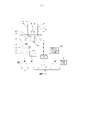
[0031] На ФИГ. 1 показана принципиальная схема системы привода тента с двойным силовым приводом в соответствии с вариантом реализации настоящего изобретения; и[0031] FIG. 1 is a schematic diagram of a dual power tarpaulin drive system in accordance with an embodiment of the present invention; and
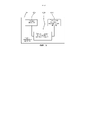
[0032] На ФИГ. 2 показана структурная схема транспортного средства в соответствии с вариантом реализации настоящего изобретения.[0032] FIG. 2 is a block diagram of a vehicle according to an embodiment of the present invention.
[0033] Номера позиций на ФИГ. 1 и 2 соответствуют следующим компонентам:[0033] Reference numbers in FIG. 1 and 2 correspond to the following components:
[0034] 10 - гидравлический двигатель; 20 - клапанный узел управления; 21 - перепускной клапан; 22 - маслоподводящий трубопровод; 24 - электромагнитный направляющий клапан; 241 - первое масляное отверстие; 242 - второе масляное отверстие; 243 - третье масляное отверстие; 26 - первый трубопровод управления; 28 - второй трубопровод управления; 29 - фильтр; 30 - первый силовой узел; 32 - второй силовой узел; 34 - первый масляный насос; 40 - второй силовой узел; 42 - механизм отбора мощности; 44 - второй масляный насос; 46 - передаточный вал; 48 - третий масляный насос; 50 - контроллер; 60 - масляный бак; 70 - тормозное устройство; 72 - челночный клапан; 74 - приводной масляный гидравлический цилиндр; 100 - система привода тента с двойным силовым приводом; 110 - подъемный масляный гидравлический цилиндр; 120 - тентовый механизм и 130 - корпус транспортного средства.[0034] 10 - hydraulic motor; 20 - valve control unit; 21 - bypass valve; 22 - oil supply pipeline; 24 - electromagnetic directional valve; 241 - first oil hole; 242 - second oil hole; 243 - third oil hole; 26 - the first control pipeline; 28 - second control pipeline; 29 - filter; 30 - the first power unit; 32 - the second power unit; 34 - the first oil pump; 40 - the second power unit; 42 - power take-off mechanism; 44 - second oil pump; 46 - transmission shaft; 48 - third oil pump; 50 - controller; 60 - oil tank; 70 - braking device; 72 - shuttle valve; 74 - drive oil hydraulic cylinder; 100 - tarpaulin drive system with double power drive; 110 - lifting oil hydraulic cylinder; 120 - awning mechanism and 130 - vehicle body.
ОСУЩЕСТВЛЕНИЕ ИЗОБРЕТЕНИЯIMPLEMENTATION OF THE INVENTION
[0035] Чтобы сделать задачи, признаки и преимущества настоящего изобретения более очевидными и легко понятными, настоящее изобретение будет подробно описано ниже со ссылкой на прилагаемые чертежи и конкретные реализации. Следует отметить, что варианты реализации настоящего изобретения и признаки в этих вариантах реализации могут быть объединены друг с другом, если нет противоречия.[0035] In order to make the objects, features and advantages of the present invention more obvious and easily understood, the present invention will be described in detail below with reference to the accompanying drawings and specific implementations. It should be noted that the embodiments of the present invention and the features in these embodiments may be combined with each other if there is no conflict.
[0036] В последующем описании изложено множество конкретных деталей, чтобы облегчить полное понимание настоящего изобретения, однако настоящее изобретение может быть также осуществлено другими способами, отличным от описанных в настоящем документе, и, следовательно, объем защиты настоящего изобретения не ограничивается конкретными вариантами реализации, раскрытыми ниже.[0036] In the following description, many specific details are set forth in order to facilitate a thorough understanding of the present invention, however, the present invention may also be practiced in other ways than those described herein, and therefore, the protection scope of the present invention is not limited to the specific embodiments disclosed. below.
[0037] Следует отметить, что транспортное средство в настоящем изобретении представляет собой саморазгружающийся грузовой автомобиль, а система 100 привода тента с двойным силовым приводом в соответствии с настоящим изобретением выполнена с возможностью приведения в действие тентового механизма 120 саморазгружающегося грузового автомобиля для управления открытием и закрытием тента.[0037] It should be noted that the vehicle in the present invention is a self-dumping truck, and the dual power
[0038] Система привода тента с двойным силовым приводом и транспортное средство в соответствии с некоторыми вариантами реализации настоящего изобретения проиллюстрированы ниже со ссылкой на ФИГ. 1 и 2.[0038] A dual power tarpaulin drive system and a vehicle in accordance with some embodiments of the present invention are illustrated below with reference to FIG. 1 and 2.
[0039] Как показано на ФИГ. 1, согласно настоящему изобретению и варианту реализации настоящего изобретения предложена система 100 привода тента с двойным силовым приводом. Система выполнена с возможностью приведения в действие тентового механизма 120 транспортного средства и включает в себя гидравлический двигатель 10, клапанный узел 20 управления, первый силовой узел 30, второй силовой узел 40 и контроллер 50. Гидравлический двигатель 10 соединен с тентовым механизмом 120, клапанный узел 20 управления соединен с гидравлическим двигателем 10, а первый силовой узел 30 соединен с клапанным узлом 20 управления. Второй силовой узел 40 соединен с клапанным узлом 20 управления. Контроллер 50 соединен с клапанным узлом 20 управления, первым силовым узлом 30 и вторым силовым узлом 40. Контроллер 50 обеспечивает силовой привод для гидравлического двигателя 10 путем управления первым силовым узлом 30 или вторым силовым узлом 40 для приведения его в действие, и контроллер 50 управляет гидравлическим двигателем 10 для приведения его во вращение путем управления клапанным узлом 20 управления для приведения его в действие.[0039] As shown in FIG. 1, according to the present invention and an embodiment of the present invention, a dual power
[0040] В этой конфигурации контроллер 50 может выбрать первый силовой узел 30 или второй силовой узел 40, чтобы обеспечить силовой привод для гидравлического двигателя 10 в соответствии с различными условиями работы для удовлетворения требований водителя к системе привода тента в различных условиях работы.[0040] In this configuration, the
[0041] В частности, как показано на ФИГ. 1, в варианте реализации настоящего изобретения система 100 привода тента с двойным силовым приводом также включает в себя масляный бак 60, а первый силовой узел 30 и второй силовой узел 40 сообщаются с масляным баком 60.[0041] In particular, as shown in FIG. 1, in an embodiment of the present invention, the dual power
[0042] В этой конфигурации масляный бак 60 содержит гидравлическое масло, а первый силовой узел 30 и второй силовой узел 40 выполнены с возможностью закачки гидравлического масла из масляного бака 60 в гидравлический двигатель 10. Таким образом, для гидравлического двигателя 10 обеспечивается силовой привод, поэтому может быть обеспечено нормальное вращение гидравлического двигателя 10 для приведения в действие тентового механизма 120, тем самым обеспечивая возможность нормального закрытия и открытия тента.[0042] In this configuration, the
[0043] В частности, как показано на ФИГ. 1, в варианте реализации настоящего изобретения первый силовой узел 30 включает в себя электродвигатель 32 и первый масляный насос 34, причем электродвигатель 32 соединен с первым масляным насосом 34 и контроллером 50, первый масляный насос 34 снабжен первым масловпускным отверстием и первым масловыпускным отверстием, при этом первое масловпускное отверстие сообщается с масляным баком 60, а первое масловыпускное отверстие сообщается с клапанным узлом 20 управления.[0043] In particular, as shown in FIG. 1, in an embodiment of the present invention, the
[0044] В этой конфигурации первый силовой узел 30 представляет собой узел электропривода, а первый масляный насос 34 приводится в действие для работы электродвигателем 32, чтобы обеспечить силовой привод для гидравлического двигателя 10. Когда требования к движущей силе и скорости приведения в действие тента не высоки, но требуется, чтобы транспортное средство было в состоянии управлять действием тента во время движения, контроллер 50 может выбрать первый силовой узел 30 для обеспечения силового привода для гидравлического двигателя 10, тем самым удовлетворяя требования водителя к системе привода тента в этих условиях работы.[0044] In this configuration, the
[0045] В частности, как показано на ФИГ. 1, в варианте реализации настоящего изобретения второй силовой привод 40 включает в себя механизм 42 отбора мощности, второй масляный насос 44 и передаточный вал 46. Механизм 42 отбора мощности соединен с контроллером 50. Второй масляный насос 44 снабжен вторым масловпускным отверстием и вторым масловыпускным отверстием. Второе масловпускное отверстие сообщается с масляным баком 60. Второе масловыпускное отверстие сообщается с клапанным узлом 20 управления. Один конец передаточного вала 46 соединен с механизмом 42 отбора мощности, а другой конец передаточного вала соединен со вторым масляным насосом 44.[0045] In particular, as shown in FIG. 1, in an embodiment of the present invention, the
[0046] В этой конфигурации второй силовой узел 40 представляет собой узел гидравлического привода, силовой привод от двигателя получают посредством механизма 42 отбора мощности, чтобы вращать передаточный вал 46, а передаточный вал 46 может приводить в действие второй масляный насос 44 для обеспечения силового привода для гидравлического двигателя 10. Когда саморазгружающийся грузовой автомобиль действительно работает, требования к движущей силе и скорости приведения в действие тента высоки, и контроллер 50 может выбрать второй силовой узел 40 для обеспечения силового привода для гидравлического двигателя 10, тем самым удовлетворяя требования водителя к системе привода тента в этих условиях работы.[0046] In this configuration, the
[0047] Следует отметить, что когда саморазгружающийся грузовой автомобиль действительно работает, высота загруженного грунта немного выше кузова грузового автомобиля, и тентовый механизм 120, имеющий большую действующую силу и высокую скорость, может сгладить грунт, чтобы избавить водителя от разравнивания грунта вручную. В этом случае для обеспечения силового привода для гидравлического двигателя 10 может быть выбран второй силовой узел 40.[0047] It should be noted that when the self-dumping truck is actually in operation, the height of the loaded soil is slightly higher than the truck body, and the
[0048] В частности, как показано на ФИГ. 1, в варианте реализации настоящего изобретения транспортное средство также включает в себя подъемный масляный гидравлический цилиндр 110, а второй силовой узел 40 также включает в себя третий масляный насос 48, причем третий масляный насос 48 позволяет проникать передаточному валу 46 и третий масляный насос снабжен третьим масловпускным отверстием и третьим масловыпускным отверстием, при этом третье масловпускное отверстие сообщается с масляным баком 60, а третье масловыпускное отверстие сообщается с подъемным масляным гидравлическим цилиндром 110.[0048] In particular, as shown in FIG. 1, in an embodiment of the present invention, the vehicle also includes a lifting
[0049] В этой конфигурации второй силовой узел 40 получает мощность двигателя посредством механизма 42 отбора мощности, чтобы приводить во вращение передаточный вал 46. Передаточный вал 46 может приводить в действие третий масляный насос 48, чтобы обеспечивать силовой привод для подъемного масляного гидравлического цилиндра 110. Таким образом, второй силовой узел 40 может обеспечивать силовой привод для гидравлического двигателя 10 и подъемного масляного гидравлического цилиндра 110 одновременно, тем самым обеспечивая нормальную работу подъемного масляного гидравлического цилиндра 110.[0049] In this configuration, the
[0050] В частности, как показано на ФИГ. 1, в варианте реализации настоящего изобретения гидравлический двигатель 10 снабжен первым отверстием управления и вторым отверстием управления, а клапанный узел 20 управления включает в себя маслоподводящий трубопровод 22, электромагнитный направляющий клапан 24, первый трубопровод 26 управления и второй трубопровод 28 управления. Один конец маслоподводящего трубопровода 22 соединен с первым силовым узлом 30 и вторым силовым узлом 40. Электромагнитный направляющий клапан 24 снабжен первым масляным отверстием 241, вторым масляным отверстием 242 и третьим масляным отверстием 243. Первое масляное отверстие 241 соединено с другим концом маслоподводящего трубопровода 22. Один конец первого трубопровода 26 управления соединен с первым отверстием управления, а другой конец первого трубопровода управления соединен со вторым масляным отверстием 242. Один конец второго трубопровода 28 управления соединен со вторым отверстием управления, а другой конец второго трубопровода управления соединен с третьим масляным отверстием 243.[0050] In particular, as shown in FIG. 1, in an embodiment of the present invention, the
[0051] В этой конфигурации электромагнитный направляющий клапан 24 выполнен с возможностью управления гидравлическим маслом таким образом, чтобы оно протекало в первый трубопровод 26 управления из второго трубопровода 28 управления, или управления гидравлическим маслом таким образом, чтобы оно протекало во второй трубопровод 28 управления из первого трубопровода 26 управления. Таким образом, гидравлическим маслом можно управлять так, чтобы оно протекало в гидравлический двигатель 10 из первого отверстия управления или второго отверстия управления, тем самым управляя направлением вращения гидравлического двигателя 10 и также управляя действием тентового механизма 120 так, чтобы тент закрывался или открывался.[0051] In this configuration, the electromagnetic
[0052] В частности, как показано на ФИГ. 1, в варианте реализации настоящего изобретения клапанный узел 20 управления также включает в себя фильтр 29, и фильтр 29 расположен на маслоподводящем трубопроводе 22.[0052] In particular, as shown in FIG. 1, in an embodiment of the present invention, the
[0053] В этой конфигурации фильтр 29 выполняет функцию фильтрации гидравлического масла, и поэтому можно обеспечить, чтобы гидравлическое масло, поступающее в гидравлический двигатель 10, удовлетворяло требованиям к чистоте при использовании, тем самым обеспечивая нормальную работу гидравлического двигателя 10.[0053] In this configuration, the
[0054] В частности, как показано на ФИГ. 1, в варианте реализации настоящего изобретения клапанный узел 20 управления также включает в себя перепускной клапан 21, и перепускной клапан 21 расположен на маслоподводящем трубопроводе 22.[0054] In particular, as shown in FIG. 1, in an embodiment of the present invention, the
[0055] В этой конфигурации перепускной клапан 21 выполняет функцию защиты от избыточного потока, что позволяет решить проблему повреждения трубопровода и частей клапанного узла 20 управления из-за чрезмерного давления, чтобы обеспечить нормальную работу клапанного узла 20 управления.[0055] In this configuration, the
[0056] В частности, как показано на ФИГ. 1, в варианте реализации настоящего изобретения система 100 привода тента с двумя силовыми приводами также включает в себя тормозное устройство 70. Тормозное устройство 70 соединено с клапанным узлом 20 управления. Когда гидравлический 10 двигатель работает, тормозное устройство 70 разблокировано, а когда гидравлический двигатель 10 не работает, тормозное устройство 70 заблокировано.[0056] In particular, as shown in FIG. 1, in an embodiment of the present invention, the dual-actuator
[0057] В этой конфигурации, когда гидравлический двигатель 10 работает, тормозное устройство 70 разблокировано, а когда гидравлический двигатель 10 не работает, тормозное устройство 70 заблокировано. Таким образом решена проблема повреждения гидравлического двигателя 10 из-за вращения гидравлического двигателя 10 под действием силы тяжести, чтобы продлить срок службы гидравлического двигателя 10. Кроме того, решена проблема соскальзывания тента тентового механизма 120 под действием силы тяжести, когда контейнер поднят, поскольку гидравлический двигатель 10 выполнен с возможностью вращения под действием внешней силы при разблокировании.[0057] In this configuration, when the
[0058] Следует отметить, что, как показано на ФИГ. 1, в варианте реализации настоящего изобретения тормозное устройство 70 включает в себя челночный клапан 72 и приводной масляный гидравлический цилиндр 74. Челночный клапан 72 снабжен двумя впускными отверстиями. Эти два впускных отверстия сообщаются с первым трубопроводом 26 управления и вторым трубопроводом 28 управления, соответственно. Челночный клапан 72 также снабжен выпускным отверстием. Выпускное отверстие сообщается с приводным масляным гидравлическим цилиндром 74. Внутри корпуса цилиндра приводного масляного гидравлического цилиндра 74 предусмотрена пружина. Шток поршня приводного масляного гидравлического цилиндра 74 выдвигается и под действием упругой силы пружины прижимается к гидравлическому двигателю 10, чтобы заблокировать гидравлический двигатель 10. В этом случае тормозное устройство 70 заблокировано, т.е. находится в исходном состоянии. Когда масло поступает в первый трубопровод 26 управления или второй трубопровод 28 управления, гидравлический двигатель 10 начинает работать, а масло также поступает в приводной масляный гидравлический цилиндр 74, и шток поршня (тормозной поршень или тормоз) втягивается и не соприкасается с гидравлическим двигателем 10. В этом случае тормозное устройство 70 разблокировано.[0058] It should be noted that, as shown in FIG. 1, in an embodiment of the present invention, the
[0059] Ниже будет описан принцип работы системы 100 привода тента с двойным силовым приводом согласно настоящему изобретению:[0059] The operating principle of the dual power
[0060] 1. Принцип работы, когда транспортное средство не движется:[0060] 1. Working principle when the vehicle is not moving:
[0061] Контроллер 50 определяет, что транспортное средство не движется. Когда водитель приводит в действие тент под управлением контроллера 50 электродвигатель 32 выключается, первый масляный насос 34 не работает, механизм 42 отбора мощности работает и приводит во вращение двухступенчатый насос, состоящий из второго масляного насоса 44 и третьего масляного насоса 48, и второй масляный насос 44 выдает масло высокого давления, которое достигает электромагнитного направляющего клапана 24 через одноходовой клапан и фильтр 29. Если электромагнитный направляющий клапан 24 находится в левом или правом положении, гидравлический двигатель 10 может вращаться, приводя в действие тентовый механизм 120. Если электромагнитный направляющий клапан 24 находится в среднем положении, масло высокого давления выгружается, и тентовый механизм 120 не действует.[0061] The
[0062] 2. Принцип работы, когда транспортное средство движется:[0062] 2. Working principle when the vehicle is moving:
[0063] Контроллер 50 определяет, что транспортное средство движется. Когда водитель приводит в движение тент, под управлением контроллера 50 механизм 42 отбора мощности не работает, электродвигатель 32 включен, и первый масляный насос 34 работает. Первый масляный насос 34 выдает масло высокого давления, которое достигает электромагнитного направляющего клапана через одноходовой клапан 24 и фильтр 29. Если электромагнитный направляющий клапан 24 находится в левом или правом положении, гидравлический двигатель 10 может вращаться, приводя в действие тентовый механизм 120. Если электромагнитный направляющий клапан 24 находится в среднем положении, масло высокого давления выгружается, и тентовый механизм 120 не действует.[0063] The
[0064] Следует отметить, что контроллер 50 задает логику управления, и поэтому электродвигатель 32 и механизм 42 отбора мощности не могут работать одновременно.[0064] It should be noted that the
[0065] Как показано на ФИГ. 2, в настоящем изобретении также предложено транспортное средство. Транспортное средство включает в себя корпус 130 транспортного средства, подъемный масляный гидравлический цилиндр 110, тентовый механизм 120 и систему 100 привода тента с двойным силовым приводом по любому из вариантов реализации первого аспекта. Система 100 привода тента с двойным силовым приводом соединена с подъемным масляным гидравлическим цилиндром 110 и тентовым 120 механизмом.[0065] As shown in FIG. 2, the present invention also provides a vehicle. The vehicle includes a
[0066] В этой конфигурации транспортное средство содержит систему 100 привода тента с двойным силовым приводом, и поэтому транспортное средство имеет функцию автоматического приведения в действие тента, что улучшает функции транспортного средства и также удовлетворяет требования транспортного средства к многофункциональности.[0066] In this configuration, the vehicle includes a dual power
[0067] Транспортное средство, предложенное в этом варианте реализации второго аспекта настоящего изобретения, включает в себя систему 100 привода тента с двойным силовым приводом по любому из вариантов реализации первого аспекта и соответственно имеет все полезные эффекты любого из этих вариантов реализации, которые здесь не повторяются.[0067] The vehicle provided in this embodiment of the second aspect of the present invention includes the dual power
[0068] Система 100 привода тента с двойным силовым приводом и транспортное средство согласно настоящему изобретению имеют следующие преимущества:[0068] The dual power
[0069] 1. Настоящее изобретение имеет преимущества как полного гидравлического привода, так и чисто электрического привода для тентового механизма 120.[0069] 1. The present invention has the advantages of both a full hydraulic drive and a purely electric drive for the
[0070] 2. Когда второй силовой узел 40 использует полный гидравлический привод, тентовый механизм 120 имеет большую действующую силу и высокую скорость. Когда высота загруженного грунта немного выше кузова грузового автомобиля, тентовый механизм 120, имеющий большую действующую силу и высокую скорость, может сгладить грунт, чтобы избавить водителя от разравнивания грунта вручную.[0070] 2. When the
[0071] 3. Когда первый силовой узел 30 использует привод от двигателя, автомобиль выполнен с возможностью приведения в действие тента во время движения или остановки, тем самым решая проблему необходимости остановки транспортного средства водителем после загрузки и разгрузки грунта и ожидания завершения открытия или закрытия тента перед началом движения, и повышая эффективность работы.[0071] 3. When the
[0072] Из описания видно, что контроллер 50 может выбрать первый силовой узел 30 или второй силовой узел 40, чтобы обеспечить силовой привод для гидравлического двигателя 10 в соответствии с различными условиями работы для удовлетворения требований водителя к системе привода тента в различных условиях работы.[0072] It can be seen from the description that the
[0073] В настоящем изобретении термины «первый», «второй» и «третий» используются просто для описания и не должны трактоваться как указывающие или означающие относительную важность, а термин «множество» чего-либо означает два или более, если иное не указано в явном виде. Термины «установить», «соединить», «соединенный», «закрепить» и т.д. следует трактовать в широком смысле. Например, «соединенный» может означать неподвижно соединенный, или соединенный с возможностью отсоединения, или соединенный как единое целое. «Соединенный» может означать соединенный непосредственно или соединенный опосредованно с помощью промежуточного средства. Специалисты в данной области могут понимать конкретные значения вышеуказанных терминов в настоящем документе в зависимости от конкретных обстоятельств.[0073] In the present invention, the terms "first", "second" and "third" are used merely for description and should not be construed as indicating or meaning relative importance, and the term "many" of something means two or more, unless otherwise indicated. explicitly. The terms "install", "connect", "connected", "fix", etc. should be interpreted in a broad sense. For example, "connected" can mean permanently connected, or connected with the possibility of detachment, or connected as a whole. "Connected" can mean connected directly or connected indirectly through an intermediate means. Specialists in this field can understand the specific meanings of the above terms in this document, depending on the specific circumstances.
[0074] В описании настоящего изобретения следует понимать, что отношения ориентации или положения, указанные терминами «вверху», «внизу», «слева», «справа», «спереди», «сзади» и т.д., основаны на отношениях ориентации или положения, показанных на прилагаемых чертежах, и предназначены просто для облегчения описания настоящего изобретения и упрощения этого описания, а не для того, чтобы указывать или подразумевать, что упоминаемое устройство или элемент должны иметь конкретную ориентацию или быть сконструированы и работать в конкретной ориентации, и, следовательно, не должны трактоваться как ограничивающие настоящее изобретение.[0074] In the description of the present invention, it should be understood that the orientation or position relationships indicated by the terms "top", "bottom", "left", "right", "front", "rear", etc., are based on the relationship orientations or positions shown in the accompanying drawings and are merely intended to facilitate the description of the present invention and to simplify this description, and not to indicate or imply that the device or element referred to must have a particular orientation or be designed and operated in a particular orientation, and therefore should not be construed as limiting the present invention.
[0075] В описании термины «вариант реализации», «некоторые варианты реализации», «конкретные варианты реализации» и т.д. указывают, что конкретные признаки, структуры, материалы или характеристики, описанные в связи с данным вариантом реализации или примером, охвачены по меньшей мере в одном варианте реализации или примере настоящего изобретения. В описании схематические описания вышеуказанных терминов необязательно относятся к одному и тому же варианту реализации или примеру. Кроме того, описанные конкретные признаки, структуры, материалы или характеристики могут быть объединены подходящим образом в любом одном или более вариантах реализации или примерах.[0075] In the description, the terms "implementation", "some implementations", "specific implementations", etc. indicate that specific features, structures, materials, or characteristics described in connection with a given embodiment or example are covered by at least one embodiment or example of the present invention. In the description, the schematic descriptions of the above terms do not necessarily refer to the same implementation variant or example. In addition, the specific features, structures, materials, or characteristics described may be combined as appropriate in any one or more embodiments or examples.
[0076] Вышеприведенное просто иллюстрирует предпочтительные варианты реализации настоящего изобретения и не предназначено для ограничения настоящего изобретения, и специалистами в данной области могут быть внесены различные изменения и модификации. Любая модификация, эквивалентная замена, усовершенствование и т.д. в рамках сущности и принципов настоящего изобретения предполагаются попадающими в объем защиты настоящего изобретения.[0076] The foregoing simply illustrates the preferred embodiments of the present invention and is not intended to limit the present invention, and various changes and modifications may be made by those skilled in the art. Any modification, equivalent replacement, improvement, etc. within the spirit and principles of the present invention are intended to fall within the protection scope of the present invention.
Claims (27)
Applications Claiming Priority (1)
| Application Number | Priority Date | Filing Date | Title |
|---|---|---|---|
| CN202011633089.7 | 2020-12-31 |
Publications (1)
| Publication Number | Publication Date |
|---|---|
| RU2785373C1 true RU2785373C1 (en) | 2022-12-07 |
Family
ID=
Cited By (1)
| Publication number | Priority date | Publication date | Assignee | Title |
|---|---|---|---|---|
| RU2826335C1 (en) * | 2022-07-28 | 2024-09-09 | Сани Хэви Эквипмент Ко., Лтд. | Hydraulic system and engineering machine |
Citations (4)
| Publication number | Priority date | Publication date | Assignee | Title |
|---|---|---|---|---|
| CN106467053A (en) * | 2015-08-21 | 2017-03-01 | 湖南汽车制造有限责任公司 | A kind of vehicle |
| CN107856533A (en) * | 2017-11-24 | 2018-03-30 | 湖南汽车制造有限责任公司 | A kind of dumper |
| CN207420999U (en) * | 2017-10-31 | 2018-05-29 | 湖南汽车制造有限责任公司 | A kind of tarpaulin mechanism fluid power system and dumper |
| CN108757602A (en) * | 2018-08-27 | 2018-11-06 | 中铁工程装备集团有限公司 | Drill jumbo air-conditioning double-power hydraulic control system and drill jumbo |
Patent Citations (4)
| Publication number | Priority date | Publication date | Assignee | Title |
|---|---|---|---|---|
| CN106467053A (en) * | 2015-08-21 | 2017-03-01 | 湖南汽车制造有限责任公司 | A kind of vehicle |
| CN207420999U (en) * | 2017-10-31 | 2018-05-29 | 湖南汽车制造有限责任公司 | A kind of tarpaulin mechanism fluid power system and dumper |
| CN107856533A (en) * | 2017-11-24 | 2018-03-30 | 湖南汽车制造有限责任公司 | A kind of dumper |
| CN108757602A (en) * | 2018-08-27 | 2018-11-06 | 中铁工程装备集团有限公司 | Drill jumbo air-conditioning double-power hydraulic control system and drill jumbo |
Cited By (2)
| Publication number | Priority date | Publication date | Assignee | Title |
|---|---|---|---|---|
| RU2840994C2 (en) * | 2022-02-25 | 2025-05-30 | Сани Аутомобиле Хоистинг Машинери Ко., Лтд. | Lowering hydraulic control method, lowering hydraulic control system and engineering equipment |
| RU2826335C1 (en) * | 2022-07-28 | 2024-09-09 | Сани Хэви Эквипмент Ко., Лтд. | Hydraulic system and engineering machine |
Similar Documents
| Publication | Publication Date | Title |
|---|---|---|
| US12410046B2 (en) | Fork leveling system and method, and telescopic boom forklift | |
| EP3779211B1 (en) | Fluid pressure circuit | |
| CN201309504Y (en) | System for lifting and steering a rigid mine self-dumping truck | |
| US9631613B2 (en) | Hydraulic drive device for cargo handling vehicle | |
| CN113928981B (en) | Engineering vehicle and hydraulic driving system thereof | |
| CN213472901U (en) | Safety device of lifting system and dump truck | |
| CN112594240B (en) | Hydraulic system of working device, control method and electric loader | |
| CN101367347B (en) | Lifting and steering control method and system of self-discharging vehicle for rigid mining | |
| CA2916444C (en) | Hydraulic pressure control device for construction machinery | |
| RU2785373C1 (en) | Twin power drive system and vehicle | |
| CN106314137B (en) | A kind of walking control for brake hydraulic system and scissor aerial work platform | |
| WO2022142169A1 (en) | Dual-power tarpaulin driving system and vehicle | |
| CN112585361B (en) | Construction machine | |
| CN107856533A (en) | A kind of dumper | |
| CN207420999U (en) | A kind of tarpaulin mechanism fluid power system and dumper | |
| CN111395906A (en) | Hydraulic control mechanism for airplane cabin door | |
| CN216190906U (en) | Arm type hydraulic energy-saving control system for overhead working truck | |
| CN215166030U (en) | Hydraulic motor control system for electric loader | |
| CN115898984A (en) | A pure electric mining dump truck hydraulic system | |
| CN105172651B (en) | A vehicle energy saving control system | |
| CN108167279B (en) | A hydraulic drive system for beach vehicles and its application | |
| CN111442008A (en) | Differential balance valve for controlling extending arm of high-altitude operation vehicle | |
| CN119553749B (en) | Loader stabilizing module, hydraulic system and loader | |
| EP4545809A1 (en) | Hydraulic drive device | |
| JPH10316054A (en) | Cabin opening/closing device for industrial vehicle |