RU2777064C1 - Apparatus for deep purification of metals - Google Patents
Apparatus for deep purification of metals Download PDFInfo
- Publication number
- RU2777064C1 RU2777064C1 RU2021117786A RU2021117786A RU2777064C1 RU 2777064 C1 RU2777064 C1 RU 2777064C1 RU 2021117786 A RU2021117786 A RU 2021117786A RU 2021117786 A RU2021117786 A RU 2021117786A RU 2777064 C1 RU2777064 C1 RU 2777064C1
- Authority
- RU
- Russia
- Prior art keywords
- distillation
- crucible
- temperature
- flask
- reactor
- Prior art date
Links
- 229910052751 metal Inorganic materials 0.000 title claims abstract description 61
- 239000002184 metal Substances 0.000 title claims abstract description 61
- 150000002739 metals Chemical class 0.000 title claims abstract description 12
- 238000000746 purification Methods 0.000 title abstract description 11
- 238000004821 distillation Methods 0.000 claims abstract description 109
- 238000000034 method Methods 0.000 claims abstract description 52
- 238000011068 loading method Methods 0.000 claims abstract description 22
- -1 ferrous metals Chemical class 0.000 claims abstract description 7
- 230000002441 reversible effect Effects 0.000 claims abstract description 3
- 239000000463 material Substances 0.000 claims description 34
- 238000004140 cleaning Methods 0.000 claims description 19
- 239000000155 melt Substances 0.000 claims description 19
- 238000001914 filtration Methods 0.000 claims description 14
- 238000013461 design Methods 0.000 claims description 6
- 238000001704 evaporation Methods 0.000 claims description 6
- 230000008020 evaporation Effects 0.000 claims description 4
- 238000009736 wetting Methods 0.000 claims description 4
- 230000000284 resting effect Effects 0.000 claims description 2
- 230000015572 biosynthetic process Effects 0.000 claims 1
- 238000004519 manufacturing process Methods 0.000 abstract description 6
- 239000000126 substance Substances 0.000 abstract description 5
- 238000005272 metallurgy Methods 0.000 abstract description 3
- 230000000694 effects Effects 0.000 abstract description 2
- 238000005516 engineering process Methods 0.000 abstract description 2
- 238000002844 melting Methods 0.000 description 18
- 230000008018 melting Effects 0.000 description 18
- 239000012535 impurity Substances 0.000 description 17
- VYPSYNLAJGMNEJ-UHFFFAOYSA-N silicon dioxide Inorganic materials O=[Si]=O VYPSYNLAJGMNEJ-UHFFFAOYSA-N 0.000 description 11
- 239000010453 quartz Substances 0.000 description 9
- OKTJSMMVPCPJKN-UHFFFAOYSA-N Carbon Chemical compound [C] OKTJSMMVPCPJKN-UHFFFAOYSA-N 0.000 description 8
- 239000007789 gas Substances 0.000 description 8
- 229910002804 graphite Inorganic materials 0.000 description 7
- 239000010439 graphite Substances 0.000 description 7
- IJGRMHOSHXDMSA-UHFFFAOYSA-N Atomic nitrogen Chemical compound N#N IJGRMHOSHXDMSA-UHFFFAOYSA-N 0.000 description 6
- 239000000047 product Substances 0.000 description 6
- 229910052714 tellurium Inorganic materials 0.000 description 6
- 238000007670 refining Methods 0.000 description 5
- 230000003247 decreasing effect Effects 0.000 description 4
- 238000007872 degassing Methods 0.000 description 4
- 238000011049 filling Methods 0.000 description 4
- 238000010438 heat treatment Methods 0.000 description 4
- 239000011261 inert gas Substances 0.000 description 4
- 239000000203 mixture Substances 0.000 description 4
- 239000007858 starting material Substances 0.000 description 4
- 238000012546 transfer Methods 0.000 description 4
- 229910052793 cadmium Inorganic materials 0.000 description 3
- 238000010586 diagram Methods 0.000 description 3
- 229910052757 nitrogen Inorganic materials 0.000 description 3
- 230000003647 oxidation Effects 0.000 description 3
- 238000007254 oxidation reaction Methods 0.000 description 3
- 229910052725 zinc Inorganic materials 0.000 description 3
- 239000011701 zinc Substances 0.000 description 3
- XKRFYHLGVUSROY-UHFFFAOYSA-N Argon Chemical compound [Ar] XKRFYHLGVUSROY-UHFFFAOYSA-N 0.000 description 2
- CWYNVVGOOAEACU-UHFFFAOYSA-N Fe2+ Chemical compound [Fe+2] CWYNVVGOOAEACU-UHFFFAOYSA-N 0.000 description 2
- 229910052799 carbon Inorganic materials 0.000 description 2
- 238000011109 contamination Methods 0.000 description 2
- 238000001816 cooling Methods 0.000 description 2
- 238000005520 cutting process Methods 0.000 description 2
- 238000011161 development Methods 0.000 description 2
- 239000012467 final product Substances 0.000 description 2
- 238000009434 installation Methods 0.000 description 2
- 239000012299 nitrogen atmosphere Substances 0.000 description 2
- 238000002360 preparation method Methods 0.000 description 2
- 229910052761 rare earth metal Inorganic materials 0.000 description 2
- 150000002910 rare earth metals Chemical class 0.000 description 2
- 230000002829 reductive effect Effects 0.000 description 2
- 238000000926 separation method Methods 0.000 description 2
- 238000000859 sublimation Methods 0.000 description 2
- 230000008022 sublimation Effects 0.000 description 2
- PORWMNRCUJJQNO-UHFFFAOYSA-N tellurium atom Chemical compound [Te] PORWMNRCUJJQNO-UHFFFAOYSA-N 0.000 description 2
- AACILMLPSLEQMF-UHFFFAOYSA-N 2,2-dichloroethenyl 2-ethylsulfinylethyl methyl phosphate Chemical compound CCS(=O)CCOP(=O)(OC)OC=C(Cl)Cl AACILMLPSLEQMF-UHFFFAOYSA-N 0.000 description 1
- 229910052582 BN Inorganic materials 0.000 description 1
- PZNSFCLAULLKQX-UHFFFAOYSA-N Boron nitride Chemical compound N#B PZNSFCLAULLKQX-UHFFFAOYSA-N 0.000 description 1
- 229910004613 CdTe Inorganic materials 0.000 description 1
- 229910004611 CdZnTe Inorganic materials 0.000 description 1
- BUGBHKTXTAQXES-UHFFFAOYSA-N Selenium Chemical compound [Se] BUGBHKTXTAQXES-UHFFFAOYSA-N 0.000 description 1
- HCHKCACWOHOZIP-UHFFFAOYSA-N Zinc Chemical compound [Zn] HCHKCACWOHOZIP-UHFFFAOYSA-N 0.000 description 1
- 239000000853 adhesive Substances 0.000 description 1
- 230000001070 adhesive effect Effects 0.000 description 1
- 230000002411 adverse Effects 0.000 description 1
- 238000004458 analytical method Methods 0.000 description 1
- 229910052786 argon Inorganic materials 0.000 description 1
- QVGXLLKOCUKJST-UHFFFAOYSA-N atomic oxygen Chemical compound [O] QVGXLLKOCUKJST-UHFFFAOYSA-N 0.000 description 1
- 244000309464 bull Species 0.000 description 1
- BDOSMKKIYDKNTQ-UHFFFAOYSA-N cadmium atom Chemical compound [Cd] BDOSMKKIYDKNTQ-UHFFFAOYSA-N 0.000 description 1
- 239000003990 capacitor Substances 0.000 description 1
- 230000002860 competitive effect Effects 0.000 description 1
- 150000001875 compounds Chemical class 0.000 description 1
- 239000010431 corundum Substances 0.000 description 1
- 229910052593 corundum Inorganic materials 0.000 description 1
- 239000013078 crystal Substances 0.000 description 1
- 238000009792 diffusion process Methods 0.000 description 1
- 238000009826 distribution Methods 0.000 description 1
- 238000000921 elemental analysis Methods 0.000 description 1
- 238000002474 experimental method Methods 0.000 description 1
- 238000000605 extraction Methods 0.000 description 1
- 238000005247 gettering Methods 0.000 description 1
- 238000009616 inductively coupled plasma Methods 0.000 description 1
- 238000009776 industrial production Methods 0.000 description 1
- 238000004949 mass spectrometry Methods 0.000 description 1
- 229910044991 metal oxide Inorganic materials 0.000 description 1
- 150000004706 metal oxides Chemical class 0.000 description 1
- 238000002156 mixing Methods 0.000 description 1
- 229910052760 oxygen Inorganic materials 0.000 description 1
- 239000001301 oxygen Substances 0.000 description 1
- 239000002245 particle Substances 0.000 description 1
- 239000002244 precipitate Substances 0.000 description 1
- 238000003825 pressing Methods 0.000 description 1
- 230000000717 retained effect Effects 0.000 description 1
- 238000007789 sealing Methods 0.000 description 1
- 229910052711 selenium Inorganic materials 0.000 description 1
- 239000011669 selenium Substances 0.000 description 1
- 230000003595 spectral effect Effects 0.000 description 1
- 238000005303 weighing Methods 0.000 description 1
Images


Abstract
Description
Изобретение относится к металлургии, в частности к устройствам, обеспечивающим работу технологий глубокой очистки цветных металлов, температура технологических процессов в которых не превышает 1250°С для получения металлов высокой степени чистоты.The invention relates to metallurgy, in particular to devices that ensure the operation of technologies for deep cleaning of non-ferrous metals, the temperature of technological processes in which does not exceed 1250°C to obtain metals of high purity.
Из уровня техники известны различные конструктивные решения устройств, используемых для глубокой очистки металлов, например ЕР 1335032 А1, ЕР 1335032 В1, US 6805833 В2. Однако известные устройства и способы работы с ними технически более сложны, что экономически не выгодно при промышленном производстве.From the prior art, various design solutions for devices used for deep cleaning of metals are known, for example EP 1335032 A1, EP 1335032 B1, US 6805833 B2. However, the known devices and methods of working with them are technically more complex, which is not economically advantageous in industrial production.
Разработанное устройство для глубокой очистки цветных, редких, редкоземельных металлов, можно использовать для широкого спектра материалов, при условии, что максимальная температура в нижеописанных технологических процессах не превышает 1250°С, например, для глубокой очистки металлов кадмия, цинка и теллура (далее по тексту Cd, Zn и Те). Эти ограничения (условия) вызваны эксплуатационными характеристиками конструкционных материалов предложенного устройства, в частности используемого в нем кварцевого реактора.The developed device for deep cleaning of non-ferrous, rare, rare-earth metals can be used for a wide range of materials, provided that the maximum temperature in the following technological processes does not exceed 1250 ° C, for example, for deep cleaning of cadmium, zinc and tellurium metals (hereinafter referred to as Cd, Zn and Te). These restrictions (conditions) are caused by the operational characteristics of the structural materials of the proposed device, in particular, the quartz reactor used in it.
Основной задачей при разработке устройства было создание надежного, технологически простого оборудования с высокой производительностью и эксплуатационными свойствами для реализации с его помощью конкурентоспособного, недорогого, воспроизводимого метода для получения цветных, редких, редкоземельных металлов с заданной чистотой (не хуже 99,99995 мас.%) и примесным составом при низкой затратной стоимости относительно известных в развитых странах мира производств, и, как следствие, более привлекательной продажной цены конечного продукта.The main task in the development of the device was to create a reliable, technologically simple equipment with high productivity and operational properties to implement with its help a competitive, inexpensive, reproducible method for obtaining non-ferrous, rare, rare-earth metals with a given purity (no worse than 99.99995 wt.%) and impurity composition at a low cost compared to well-known productions in the developed countries of the world, and, as a result, a more attractive selling price of the final product.
В разработанном устройстве с вертикальным расположением рабочего реактора с оснасткой, исключающей необходимость использования дополнительного охлаждения, во время технологического процесса, реактор размещается в многозонной резистивной печи с меняющимся вдоль ее оси, в процессе проведения этапов очистки, температурным градиентом. Способ очистки, реализуемый с помощью предложенного устройства, включает в себе возможность использования в одном цикле технологического процесса, при разовой загрузки материала в реактор (без вскрытия реактора и его перезагрузки), нескольких методов металлургической очистки металлов.In the developed device with a vertical arrangement of the working reactor with equipment that eliminates the need for additional cooling during the technological process, the reactor is placed in a multi-zone resistive furnace with a temperature gradient changing along its axis during the purification stages. The purification method implemented using the proposed device includes the possibility of using several methods of metallurgical purification of metals in one cycle of the technological process, with a single loading of material into the reactor (without opening the reactor and restarting it).
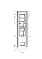
Поставленная задача решается за счет того, что устройство для глубокой очистки цветных металлов, температура технологических процессов в котором не превышает 1250°С согласно изобретению, содержит вертикально размещенную реакторную колбу с оснасткой для очистки металлов, герметично соединенный с фланцем, обеспечивающим подключение к газовой и вакуумной линиям, а также печной блок, размещенный поверх реактора и выполненный с обеспечением возможности изменения температурного режима и создания температурного градиента вдоль вертикальной оси устройства, при этом реакторная колба собрана в обратном технологическому процессу очистки порядке и включает размещенные внутри реакторной колбы снизу в верх по порядку сборки приемный тигель, конденсатор, установленную на нем вторую дистилляционную воронку, стойку дистилляционной части, тигель второй дистилляции, первую дистилляционную воронку, колбу дистилляционной части и помещенные внутри этой колбы тигель первой дистилляции и загрузочный тигель.The problem is solved due to the fact that the device for deep cleaning of non-ferrous metals, the temperature of technological processes in which does not exceed 1250°C according to the invention, contains a vertically placed reactor flask with equipment for cleaning metals, hermetically connected to a flange that provides connection to a gas and vacuum lines, as well as a furnace block placed on top of the reactor and made with the possibility of changing the temperature regime and creating a temperature gradient along the vertical axis of the device, while the reactor flask is assembled in the reverse order of the cleaning process and includes placed inside the reactor flask from bottom to top in the assembly order a receiving crucible, a condenser, a second distillation funnel mounted on it, a distillation part rack, a second distillation crucible, a first distillation funnel, a distillation part flask and a first distillation crucible and a loading crucible placed inside this flask.
В нижней части загрузочного тигля, предпочтительно в его донной части, могут быть выполнены фильтрационные отверстия.In the lower part of the feed crucible, preferably in its bottom part, filtration holes can be provided.
В верхней части загрузочного тигля может быть размещена плотно закрывающая его крышка.In the upper part of the boot crucible, a tightly closing lid can be placed.
При этом загрузочный и дистилляционные тигли целесообразнее всего изготавливать из материала, исключающего смачивание его расплавом рафинируемого вещества, например, из графита, кварца или нитрида бора, и смачиваемого окислами рафинируемого вещества.At the same time, it is most expedient to make the loading and distillation crucibles from a material that excludes its wetting by the refined substance melt, for example, from graphite, quartz or boron nitride, and the refined substance wetted by oxides.
В верхней части обоих дистилляционных тиглей могут быть выполнены технологические отверстия.Technological holes can be made in the upper part of both distillation crucibles.
Приемный тигель может быть выполнен из материала, исключающего смачивание его расплавом рафинируемого вещества.The receiving crucible can be made of a material that prevents it from being wetted by the melt of the substance being refined.
Приемный тигель предпочтительно может иметь конструкцию, обеспечивающую возможность формирования слитков заданных размеров и конфигураций. Также оба дистилляционных тигля могут быть установлены на стойки, имеющие в нижней части технологические щели-отверстия и опирающиеся на соответствующие дистилляционные воронки, а приемный тигель размещен на подставке под приемный тигель.The receiving crucible may preferably be designed to form ingots of predetermined sizes and configurations. Also, both distillation crucibles can be installed on racks having technological slots-holes in the lower part and resting on the corresponding distillation funnels, and the receiving crucible is placed on a stand for the receiving crucible.
Между колбой дистилляционной части и стойкой дистилляционной части может быть закреплен геттерный фильтр.A getter filter can be fixed between the flask of the distillation part and the stand of the distillation part.
При этом геттерный фильтр может быть размещен в устройстве на уровне поддержания температуры испарения рафинируемого металла.In this case, the getter filter can be placed in the device at the level of maintaining the evaporation temperature of the refined metal.
Причем для отсечения объемов, разграничивающих этапы технологического процесса помимо дистилляционной колбы и стойки дистилляционной части, может быть установлена дополнительная стойка дистилляционной части, выполненная подобно первой, причем в этом случае дистилляционная колба опирается на геттерный фильтр, опирающийся в свою очередь на дополнительную стойку дистилляционной части, которая размещена с опиранием на первую дистилляционную воронку, установленную на стойке дистилляционной части, помещенной на вторую дистилляционную воронку.Moreover, to cut off the volumes delimiting the stages of the technological process, in addition to the distillation flask and the stand of the distillation part, an additional stand of the distillation part can be installed, made similar to the first one, and in this case the distillation flask rests on a getter filter, which in turn rests on an additional stand of the distillation part, which is placed with support on the first distillation funnel mounted on the stand of the distillation part placed on the second distillation funnel.
Технический результат, достигаемый заявленным устройством, состоит в получении надежного, технологически простого оборудования, обеспечивающего в процессе своей работы получение цветных металлов с заданной чистотой (не хуже 99,99995 мас.%) и примесным составом при низкой затратной стоимости способа относительно стоимости известных в развитых странах мира производств, и, как следствие, более привлекательной продажной цены конечного продукта.The technical result achieved by the claimed device consists in obtaining a reliable, technologically simple equipment that provides in the course of its operation the production of non-ferrous metals with a given purity (not worse than 99.99995 wt.%) and an impurity composition at a low outlay cost of the method relative to the cost of known in developed countries of the world of production, and, as a result, a more attractive selling price of the final product.
Для осуществления способа очистки устройство обеспечивает непрерывность технологического процесса проводимого без вскрытия реакторной колбы с оснасткой и (либо) ее перезагрузки, при этом в заявленном устройстве с вертикальным расположением рабочего реактора с оснасткой исключается необходимость использования дополнительного охлаждения.To implement the cleaning method, the device ensures the continuity of the technological process carried out without opening the reactor flask with equipment and (or) its reloading, while in the claimed device with a vertical arrangement of the working reactor with equipment, the need for additional cooling is eliminated.
Схематическое изображение устройства (реакторной (рабочей) части с оснасткой) для очистки металлов, размещенного в печи показаны на фиг 1-3. Далее, в соответствии с изображениями приведено более детальное описание конструкции (устройства) и способа его работы.A schematic representation of the device (reactor (working) part with equipment) for cleaning metals placed in the furnace is shown in Figs 1-3. Further, in accordance with the images, a more detailed description of the structure (device) and its method of operation is given.
Фиг. 1 - Схематическое изображение устройства (реакторной (рабочей) части с оснасткой) для очистки металлов;Fig. 1 - Schematic representation of the device (reactor (working) part with equipment) for cleaning metals;
Фиг. 2 - тоже, с установленными стойками под дистилляционные тигли;Fig. 2 - also, with installed racks for distillation crucibles;
Фиг. 3 - тоже, что на фиг. 2, с установленным геттерным фильтром и дополнительной стойкой дистилляционной части.Fig. 3 is the same as in Fig. 2, with a getter filter installed and an additional distillation stand.
На фигурах позициями обозначено: 1 - крышка загрузочного тигля, 2 - загрузочный тигель, 3 - тигель первой дистилляции, 4 - стойка под дистилляционный тигель, 5 - стойка дистилляционной части, 6 - тигель второй дистилляции, 7 - конденсатор, 8 - приемный тигель, 9 - кварцевая реакторная колба, 10 - колба дистилляционной части, 11 - геттерный фильтр, 12 - нагревательные элементы, 13 - дистилляционная воронка, 14 - корундовый муфель, 15 - фланец с подсоединением к газовой и вакуумной линиям, 16 - подставка под приемный тигель, 17 - патрубки газовой (входной) и вакуумной (выводящий) линий.In the figures, positions are indicated: 1 - cover of the loading crucible, 2 - loading crucible, 3 - crucible of the first distillation, 4 - rack for the distillation crucible, 5 - rack of the distillation part, 6 - crucible of the second distillation, 7 - condenser, 8 - receiving crucible, 9 - quartz reactor flask, 10 - distillation part flask, 11 - getter filter, 12 - heating elements, 13 - distillation funnel, 14 - corundum muffle, 15 - flange with connection to gas and vacuum lines, 16 - stand for receiving crucible, 17 - branch pipes of the gas (inlet) and vacuum (outlet) lines.
Квазигерметичная (то есть не абсолютно герметичный, но приближенный к этому понятию) реакторная колба с оснасткой, состоящая из реакторной колбы 9, изготовленной из вакуумплотного, химически стойкого кварца и металлического, водоохлаждаемого фланца 15 соединенного герметично с колбой с помощью уплотнителей из вакуумной резины подсоединен к газовой и вакуумной линиям через патрубки 17 обеспечивающим в реакторной части вакуум с остаточным давлением в 5*10-5 мм рт.ст. и избыточное давление инертного газа (аргон или азот) в 0,3 кгс/см2.A quasi-hermetic (that is, not absolutely hermetic, but close to this concept) reactor flask with equipment, consisting of a
Оснастка, размещенная в реакторной части изготавливается из оптически чистого, вакуумплотного и химически стойкого кварца используемого в электронной промышленности, либо из высокоплотного графита не хуже марки МПГ-6, в зависимости от физико-химических свойств очищаемого материала. В ряде случаев (в зависимости от свойств очищаемых металлов) графитовые изделия полируются либо уплотняются пироуглеродом в специальных печах. Возможно использование смешанной, графитовой и кварцевой оснастки, например, тигли (2, 3, 6, 8) и воронки (13) изготавливаются из графита, а остальные изделия оснастки из кварца. Все изделия оснастки снабжены соответствующими друг другу пазами, позволяющими стыковать их между собой как конструктор, и обеспечивающими устойчивость оснастки в собранном состоянии. Кроме того, в определенных местах изделий (на схемах изображений не показано, так как это ноу-хау) имеются соответствующие разрезы, позволяющие в каждой точке собранного реактора иметь необходимое для каждого этапа технологического процесса давление вакуума или инертного газа.The equipment placed in the reactor part is made of optically pure, vacuum-tight and chemically resistant quartz used in the electronics industry, or of high-density graphite no worse than MPG-6 grade, depending on the physicochemical properties of the material being cleaned. In some cases (depending on the properties of the metals being cleaned), graphite products are polished or densified with pyrocarbon in special furnaces. It is possible to use mixed, graphite and quartz equipment, for example, crucibles (2, 3, 6, 8) and funnels (13) are made of graphite, and the rest of the equipment is made of quartz. All tooling products are equipped with grooves corresponding to each other, allowing them to be joined together as a designer, and ensuring the stability of the tooling in the assembled state. In addition, in certain places of the products (images are not shown in the diagrams, as this is know-how) there are corresponding cuts that allow at each point of the assembled reactor to have the pressure of vacuum or inert gas necessary for each stage of the technological process.
Размеры оснастки и тиглей определяются объемом очищаемого материала и могут соответственно масштабироваться. Оптимальной загрузкой исходного материала для процессов очистки таких металлов как Cd, Zn и Те, является вес до пяти килограмм. Это ограничение связано с тем, что увеличение размеров оснастки по диаметру реакторной части приводит к увеличению радиального градиента, что может плохо сказаться, на качестве очистки. Увеличение оснастки по высоте может привести к удорожанию процесса за счет усложнения конструктивных решений устройства (установки) в целом, что может быть не пропорционально к увеличению себестоимости получаемого продукта. Коэффициент масштабирования и максимальная загрузка определяется физико-химическими свойствами исходных (рафинируемых) материалов и элементов конструкции основной (реакторной) части.The dimensions of tooling and crucibles are determined by the volume of material to be cleaned and can be scaled accordingly. The optimal loading of the starting material for the purification of metals such as Cd, Zn and Te is up to five kilograms. This limitation is due to the fact that an increase in the dimensions of the tooling along the diameter of the reactor part leads to an increase in the radial gradient, which can adversely affect the quality of cleaning. An increase in the height of the tooling can lead to an increase in the cost of the process due to the complexity of the design solutions of the device (installation) as a whole, which may not be proportional to the increase in the cost of the resulting product. The scaling factor and the maximum load are determined by the physicochemical properties of the initial (refined) materials and structural elements of the main (reactor) part.
Кроме того, значительное увеличение в загрузке исходного материала может повлечь за собой эксплуатационные проблемы, связанные с изготовлением дополнительных приспособлений для эксплуатации оснастки, уменьшением срока службы элементов оснастки и устройства (установки) в целом, применением более дорогих конструкционных материалов, увеличением трудозатрат.In addition, a significant increase in the loading of the starting material can lead to operational problems associated with the manufacture of additional devices for the operation of the tooling, a decrease in the service life of the tooling elements and the device (installation) as a whole, the use of more expensive structural materials, and an increase in labor costs.
Поэтому, при конструировании устройства, учтены данные проблемы и найдены оптимальные варианты по принципу цена-качество.Therefore, when designing the device, these problems were taken into account and the best options were found according to the price-quality principle.
После загрузки навески исходного металла в загрузочный тигель 2 его плотно закрывают крышкой 1, и сборка реактора с оснасткой производится снизу вверх, поэтапно добавляя каждый элемент. После установки колбы дистилляционной части 10, одевается кварцевая реакторная колба 9, которая плотно соединяется с фланцем 16 с использованием прокладок из вакуумной резины. Соединение кварцевой реакторной колбы с металлическим фланцем через резиновый уплотнитель производят по стандартной схеме с использованием стандартных технологических решений. После уплотнения проверяем герметичность сборки путем вакуумирования реакторного пространства с проверкой натекания. Предварительно подготавливают вакуумную линию к процессу, включив форвакуумный и паромасляный (диффузионный) вакуумные насосы, подготавливают газовую линию. После проделанных операций помещают реакторную колбу в печной блок, включающий в себя муфель 14 и нагревательные элементы 12, и включают нагрев, плавно выводя на температурный профиль в печном блоке, необходимый для проведения первого (необходимого) этапа технологического процесса.After loading a sample of the initial metal into the
Принцип действия устройства при реализации способа металлургической очистки металлов описывается нижеследующим технологическим процессом.The principle of operation of the device in the implementation of the method of metallurgical purification of metals is described by the following technological process.
Первым этапом технологического процесса является фильтрация исходного материала (металла) из загрузочного тигля 2 в тигель первой дистилляции 3, который является в этом этапе процесса приемным. Тигли устанавливаются друг на друга плотно, имея пазовое соединение. Особенностью (отличием) загрузочного тигля является то, что он имеет: плотно закрывающуюся крышку 1, легкую конусность внутренней части (для удобства выгрузки тигельного остатка), в нижней части необходимое количество фильтрационных отверстий диаметром от 0,7 до 1,0 мм (в зависимости от свойств, уровня чистоты и окисления исходного материала). Тигель выполняется из материала, не смачиваемого расплавом исходного металла, при этом он должен смачиваться его окислами. Данная операция проходит при условиях низкого вакуума с остаточным давлением до 1*10-3 мм рт.ст. и температурной полкой в зоне загрузочного тигля и тигля первой дистилляции на уровне, превышающем температуру плавления обрабатываемого металла на 80÷120°С (в зависимости от свойств исходного материала). Ниже тиглей, вплоть до конденсатора 7 должна поддерживаться температура равная или слегка превышающая (не более чем на 10°С) температуру плавления очищаемого металла. Температура на конденсаторе должна быть значительно ниже температуры плавления металла. Сущность процесса фильтрации заключается в том, что после расплавления исходного металла происходит рафинирование расплава прохождением через фильтровальные отверстия. При этом происходит механическое отделение крупных неметаллических включений и адгезионная очистка тонкодисперсных неметаллических включений, которые остаются в расплаве. Кроме того при фильтрации металл попадает в тигель расположенный снизу дозировано, способствуя активному отведению с развитой поверхности стекающего вниз металла газовых пузырей и включений, отведению легколетучих примесей, которые, за счет вышеописанного технологического режима оседают на конденсаторе. На поверхности расплава в загрузочном тигле находится окисная пленка, образованная за счет естественного окисления кусочков исходной металлической загрузки помещенной в тигель перед плавлением, в которой, в частности, задерживается ряд тяжелых примесей. Окисная пленка смачивает поверхность тигля и за счет действия сил поверхностного натяжения не дает всему расплаву профильтроваться в тигель первой дистилляции. Фильтрационные отверстия и их количество подбираются таким образом, чтоб в зависимости от свойств рафинируемого материала, степени его загрязнения и окисления, за счет сил поверхностного натяжения и смачивания процесс фильтрации останавливался при тигельном остатке равном ~15% от загрузки исходного материала. Однако процесс фильтрации на этом не останавливается, некоторая очистка уже в более глубокой и сложной форме продолжается на протяжении всего технологического процесса, это вызвано, прежде всего, наличием крышки тигля, за счет которой остаточное давление в тигле отличается в большую сторону от остаточного давления в реакторе. Проходя через окисный слой и очищаясь, таким образом, пары металла уменьшают разряжение вакуума в этом объеме, поддавливая расплав и нарушая равновесие с силами поверхностного натяжения, фильтрация медленно продолжается, при этом давление в тигле доходит до определенного уровня и более не повышается, поскольку через щели между крышкой и тиглем пары выходят в дистилляционную часть реактора и конденсируются с остальным очищаемым металлом. К концу общего технологического процесса тигельный остаток должен составлять не менее 10% от общей массы начальной загрузки исходного металла.The first stage of the technological process is the filtration of the starting material (metal) from the
Необходимо отметить, что созданию различных градиентных областей по оси реактора в значительной степени возможно благодаря наличию воронок 13. Они выполняют не только свои основные функции, но и служат отличным температурным экраном, разделяя реакторную часть на технологические и температурные зоны.It should be noted that the creation of various gradient regions along the reactor axis is largely possible due to the presence of
Следующим этапом (вторым) технологического процесса является первая дистилляция отфильтрованного материала. Отфильтрованный металл находится в первом дистилляционном тигле 3, отличие которого состоит в том, что он выполнен из материала, не смачиваемого расплавом рафинируемого металла, при этом он также имеет легкую конусность в своей внутренней части для удобства извлечения тигельного остатка, его объем и размер сопоставимы с загрузочным тиглем, технологические отверстия выполнены в верхней части тигля. Технологические отверстия в дистилляционном тигле 3 должны иметь общую площадь не менее 20% от площади расплава в этом тигле, чтоб соблюсти контроль за необходимой скоростью массопереноса в процессе дистилляции. Технологический процесс на этом этапе может идти по нескольким структурным схемам. При первой в данный тигель загружается навеска геттерирующего материала, имеющая возможность химически связывать одну или несколько примесей рафинируемого металла образуя соединения, остающиеся при дальнейшей дистилляции в тигельном остатке [1]. По второй структурной схеме геттер не добавляется. Все зависит от свойств и загрязнений исходного материала.The next stage (second) of the technological process is the first distillation of the filtered material. The filtered metal is in the
Тигель устанавливается на стойку 4 имеющую в нижней части технологические щели-отверстия, которая ставится на сливную дистилляционную воронку 13, закрепленную на находящемся под ней тигле второй дистилляции. При сборке, для отсечения объемов, разграничивающих этапы технологического процесса, используют колбу 10 и стойки 5 дистилляционной части. Между колбой 10 и верхней стойкой 5 закрепляется геттерный фильтр 11, который, так же как и геттерирующая примесь, используется в процессе по необходимости, давая возможность расширить технологическую схему еще на две структурные схемы. Смысл фильтра заключается в том, что он поглощает выделяемые в процессе дистилляции газообразные примеси, которые снижаются в конденсате. Кроме того, за счет повышенной активности гетера к кислороду на нем происходит высаживание легколетучих окислов металлов, что приводит так же к дополнительной очистке от металлических примесей. При этом фильтр находится на уровне температуры испарения рафинируемого металла, поэтому он задерживает частицы основного материала [2].The crucible is mounted on a
Второй этап проводят при остаточном давлении 5*10-4 ÷ 5*10-5 мм рт. ст. в реакторной части. Температурный профиль по реактору расположен следующим образом: температура на тиглях 2 и 3 находится на температурной полке превышающей температуру плавления рафинируемого металла на 50÷60°С; по стойке 4 идет понижающийся температурный градиент, заканчивающийся на верхней воронке 13 температурой сублимации металла равной температуре плавления. До второй воронки мы поддерживаем температуру ниже температуры плавления на 20÷30°С, на конденсаторе 7 температуру опускаем до максимально возможного (от конструктивных особенностей оборудования) уровня.The second stage is carried out at a residual pressure of 5*10 -4 ÷ 5*10 -5 mm Hg. Art. in the reactor section. The temperature profile in the reactor is as follows: the temperature on the
Дистилляция происходит следующим образом. Металл, испаряясь с поверхности расплава, проходит через технологические отверстия в тигле, через геттерный фильтр и конденсируется на воронке. Элементы, имеющие более высокое давление паров, чем основной рафинируемый металл в данном случае является легколетучей примесью при данном технологическом режиме, элементы, имеющие более низкое давление паров, остаются в тигельном остатке, являясь тяжелыми примесями. Скорость дистилляции (массоперенос) определяется уровнем температур, остаточным давлением в реакторе, а так же отношением площади технологических отверстий к площади испарения. Скорость дистилляции определяем экспериментально в зависимости от технологических режимов и свойств рафинируемого материала. В процессе дистилляции часть легколетучих примесей осаждается на геттерном фильтре, а часть на конденсаторе. Рафинирование дистилляцией останавливаем при тигельном остатке равном 20% от фильтрованного материала, за счет заполнения реактора инертным газом до уровня остаточного давления равного атмосферному. После чего поднимаем температуру на верхней воронке 13 и тигле второй дистилляции 6 до уровня, превышающего температуру плавления рафинируемого металла на 90°С осуществляя слив дистиллята в тигель 6. Необходимо отметить, что при дальнейших циклах технологического процесса дистилляция из тигля 3 будет медленно продолжаться и в конечном этапе, уровень тигельного остатка в нем снизится до ~ 17% от массы отфильтрованного материала.Distillation proceeds as follows. The metal, evaporating from the surface of the melt, passes through the technological holes in the crucible, through the getter filter and condenses on the funnel. Elements having a higher vapor pressure than the main refined metal in this case is a highly volatile impurity in a given process mode, elements having a lower vapor pressure remain in the crucible residue, being heavy impurities. The distillation rate (mass transfer) is determined by the temperature level, the residual pressure in the reactor, as well as the ratio of the area of technological holes to the area of evaporation. The distillation rate is determined experimentally depending on the technological modes and properties of the material being refined. During distillation, some of the volatile impurities are deposited on the getter filter, and some on the condenser. We stop refining by distillation at a crucible residue equal to 20% of the filtered material, by filling the reactor with an inert gas to a level of residual pressure equal to atmospheric. Then we raise the temperature in the
На следующем этапе (третьем) нашего способа проводим еще один процесс дегазации легколетучих примесей в условиях низкого вакуума.At the next stage (third) of our method, we carry out another process of degassing volatile impurities under low vacuum conditions.
Данная операция проходит в два технологических цикла обеспечивающих температурные качели довольно-таки в широком диапазоне на расплаве находящемся в тигле второй дистилляции 6. Оба цикла осуществляют при условиях низкого вакуума с остаточным давлением до 1*10-3 мм рт.ст. в подреакторном пространстве. При этом, в первом цикле устанавливают следующий температурный режим: уровень температуры на тиглях 2, 3 и до верхней воронки включительно поддерживаются (по возможности) на температурной полке превышающей температуру плавления рафинируемого металла на 20÷30°С; температурную полку в зоне тигля второй дистилляции поддерживают на уровне, превышающем температуру плавления металла на 80÷120°С; до второй воронки имеют температурный градиент заканчивающийся уровнем превышающим температуру плавления на 20÷30°С; на конденсаторе 7 температуру опускают до максимально возможного (от конструктивных особенностей оборудования) уровня. После выхода оборудования на указанный режим проводят временную выдержку от 20 до 30 минут, в зависимости от свойств рафинируемого металла.This operation takes place in two technological cycles providing temperature swings in a rather wide range on the melt located in the crucible of the
На втором цикле данного этапа производят понижение температурной полки на тигле второй дистилляции до уровня, превышающем температуру плавления на 20÷30°С, с максимально возможной скоростью, все остальные технологические режимы не изменяют. После выдержки от 20 до 30 минут, выводят температурный уровень на режим соответствующий первому циклу. Операции повторяют несколько раз, в зависимости от свойств и загрязненности рафинируемого металла.In the second cycle of this stage, the temperature shelf on the crucible of the second distillation is lowered to a level exceeding the melting temperature by 20÷30°C, with the maximum possible speed, all other technological modes are not changed. After exposure from 20 to 30 minutes, the temperature level is brought to the mode corresponding to the first cycle. The operations are repeated several times, depending on the properties and impurity of the refined metal.
Выполнения данного цикла способствует отделению от поверхности расплава газовых пузырей и включений, отведению легколетучих примесей, при условии перемешивания расплава за счет изменения на нем температурного градиента, вышеупомянутые примеси и включения совместно с незначительной частью рафинируемого металла оседают на конденсаторе.The implementation of this cycle contributes to the separation of gas bubbles and inclusions from the surface of the melt, the removal of volatile impurities, subject to the mixing of the melt due to a change in the temperature gradient on it, the above impurities and inclusions, together with a small part of the refined metal, settle on the condenser.
Следующим этапом (четвертым) осуществляется вторая дистилляция рафинируемого металла. Расплав находится в тигле второй дистилляции 6, отличие которого состоит в том, что он выполнен из материала, не смачиваемого расплавом рафинируемого металла, а также он имеет легкую конусность в своей внутренней части для удобства извлечения тигельного остатка, его объем и размер меньше тигля первой дистилляции на 15%, технологические отверстия в верхней части тигля аналогичны тиглю первой дистилляции.The next stage (fourth) is the second distillation of the refined metal. The melt is in the crucible of the
Тигель второй дистилляции установлен на нижнюю стойку 4 имеющую в нижней части технологические щели-отверстия. Нижняя стойка в свою очередь установлена на нижнюю сливную дистилляционную воронку 13, закрепленную на находящемся под ней конденсаторе 7. Для отсечения объемов, разграничивающих этапы технологического процесса, используют нижнюю стойку 5 дистилляционной части. В случае использования в устройстве геттерных фильтров нижняя стойка дополнена еще одной подобной частью.The crucible of the second distillation is installed on the
Четвертый этап, как и второй, проводят при остаточном давлении 5*10-4÷5*10-5 мм рт.ст. в реакторной части. Температурный профиль по реактору расположен следующим образом: температура на тиглях 2, 3 и до верхней воронки включительно поддерживаются на температурной полке превышающей температуру плавления рафинируемого металла на 10÷15°С; на тигле второй дистилляции поддерживаем температурную полку превышающую температуру плавления на 30÷40°С; по нижней стойке 4 идет понижающийся температурный градиент, заканчивающийся на нижней воронке 13 температурой сублимации металла равной температуре плавления. На конденсаторе 7 температуру опускаем до максимально возможного (от конструктивных особенностей оборудования) уровня.The fourth stage, like the second, is carried out at a residual pressure of 5*10 -4 ÷5*10 -5 mm Hg. in the reactor section. The temperature profile in the reactor is arranged as follows: the temperature on the
Дистилляция происходит следующим образом. Металл, испаряясь с поверхности расплава, проходит через технологические отверстия в тигле, конденсируется на воронке, проходя таким же образом, как и на втором этапе, за исключением того, что уровень температуры на расплаве ниже, за счет чего ниже скорость дистилляционного процесса и эффективней процесс рафинирования. Процесс останавливаем при тигельном остатке равном 15% от фильтрованного материала, за счет заполнения реактора инертным газом до уровня остаточного давления равного атмосферному. После чего поднимаем температуру на нижней воронке 13 до уровня, превышающего температуру плавления рафинируемого металла на 90°С, а в приемном тигле 8 до уровня превышающего температуру плавления на 20°С осуществляя слив дистиллята в тигель 8. Тигель может быть выполнен в разных вариантах, позволяющих получать не только один целый слиток, но и слитки нужного размера и конфигурации, по требованиям заказчика. Кроме того размер слитков при розливе расплава может определяться диаметром лодочки для более плотной ее загрузки при дальнейшей кристаллографической очистки металла.Distillation proceeds as follows. The metal, evaporating from the surface of the melt, passes through the technological holes in the crucible, condenses on the funnel, passing in the same way as in the second stage, except that the temperature level on the melt is lower, due to which the speed of the distillation process is lower and the process is more efficient. refining. The process is stopped at a crucible residue equal to 15% of the filtered material, by filling the reactor with an inert gas to a level of residual pressure equal to atmospheric. Then we raise the temperature in the
После проведения вышеописанных операций печной блок сдвигается с реактора с оснасткой, который в свою очередь охлаждается, после чего происходит его разборка. Тигельные остатки и полученный материал извлекаются, производится отбор необходимых проб и упаковка материалов. Оснастка и реакторная колба подвергаются необходимой очистке (обработке) и подготовке к следующему процессу рафинирования.After carrying out the above operations, the furnace block is shifted from the reactor with equipment, which in turn is cooled, after which it is disassembled. The crucible residues and the resulting material are removed, the necessary samples are taken and the materials are packed. The equipment and the reactor flask are subjected to the necessary cleaning (treatment) and preparation for the next refining process.
Пример разработки аппаратной части, проведения рафинирования материалов получаемых в данном проекте, а так же подготовку основных и вспомогательных материалов включая оснастку, приведено ниже.An example of the development of hardware, the refining of materials obtained in this project, as well as the preparation of basic and auxiliary materials, including tooling, is given below.
Рассмотрим пример очистки (рафинирования) исходного Те марки Т-У произведенного по ТУ 20.13.21-096-00194429-2020. В данном примере используем устройство, проиллюстрированное фигурой 2 с оснасткой смешенного типа, часть которой выполнена из графита марки не хуже МПГ-7 по ТУ 1915-051-002008510 2005, остальные из труб кварцевого стекла по ГОСТ 15177-70. Крышка загрузочного тигля 1, загрузочный тигель 2, тигель первой дистилляции 3, тигель второй дистилляции 6, приемный тигель 8, дистилляционная воронка 13 - выполнены из графита. Стойка под дистилляционный тигель 4, стойки дистилляционной части 5, конденсатор 7, колба дистилляционной части 10 - выполнены из кварцевого стекла.Consider an example of purification (refining) of the original Te brand T-U produced according to TU 20.13.21-096-00194429-2020. In this example, we use the device illustrated in figure 2 with mixed-type equipment, part of which is made of graphite grade no worse than MPG-7 according to TU 1915-051-002008510 2005, the rest are made of quartz glass pipes according to GOST 15177-70. The lid of the
В загрузочном тигле под фильтрацию было просверлено восемь отверстий 0 0,8 мм. В тигле для дистилляции в верхней части высверлено 12 отверстий 0 10 мм. Внутренний диаметр тиглей соответствует 74 мм. Высота приемного тигля 80 мм.Eight holes Ø 0.8 mm were drilled in the loading crucible for filtration. In the crucible for distillation, 12 holes Ø 10 mm were drilled in the upper part. The inner diameter of the crucibles corresponds to 74 mm. The height of the receiving crucible is 80 mm.
Процесс проводили без использования геттерного фильтра и геттерных материалов.The process was carried out without the use of a getter filter and getter materials.
В приемный тигель 2 осуществили загрузку исходного Те массой 2,0 кг, после чего плотно закрыли крышкой 1 и в соответствии со способом осуществили сборку квазигерметичной реакторной колбы с оснасткой, одновременно подготавливая к процессу вакуумную и газораспределительную линии, подключаемые к устройству.The receiving
Параллельно выводили нагревательные элементы шестизонной печи на необходимый температурный профиль (режим) для фильтрации Те, при котором температурная полка на загрузочном тигле 2 и тигле первой дистилляции 3 составляет 570°С. Ниже тиглей, вплоть до конденсатора 7 температуру поддерживаем на уровне 460°С.In parallel, the heating elements of the six-zone furnace were brought to the required temperature profile (mode) for Te filtration, at which the temperature shelf on the
Проверяли квазигерметичную реакторную колбу с оснасткой на натекание, путем ее откачки до остаточного давления 1*10-3 мм рт.ст. Оставляя под реакторное пространство при этом же остаточном давлении, совмещали печной блок устройства с реакторным и проводили процесс фильтрации исходного Те, сделав выдержку в 30 минут после выхода температурного профиля на режим.We checked the quasi-hermetic reactor flask with equipment for leakage by evacuating it to a residual pressure of 1*10 -3 mm Hg. Leaving under the reactor space at the same residual pressure, the furnace block of the device was combined with the reactor block and the initial Te was filtered, holding for 30 minutes after the temperature profile reached the regime.
После фильтрации проводим процесс первой дистилляции Те, на которой температурный профиль в печи на уровне загрузочного тигля 3 имеет температурную полку 510°С. Далее по оси вдоль стойки под дистилляционный тигель 4 вниз идет понижающий температурный градиент до верхней дистилляционной воронки 13, на которой мы имеем температуру 450°С. Ниже, вплоть до конденсатора 7 поддерживаем температуру равную 420°С. Остаточное давление вакуума в реакторе, при этом, составляет 5*10-4 мм рт.ст.After filtration, we carry out the process of the first distillation Te, in which the temperature profile in the furnace at the level of the
Предположив, что размер тигельного остатка после фильтрации составит 10÷15% и, учитывая, что скорость массопереноса, в нашем случае составлял 190 грамм в час, делали выдержку при данных условиях дистилляции в 7 часов. После окончания выдержки, процесс дистилляции прерывался отсечением квазигерметичной реакторной колбы с оснасткой от вакуумной линии с последующим заполнением ее особо чистым азотом до остаточного давления равного атмосферному. Далее проводим сливание дистиллята во тигель второй дистилляции 6, для этого поднимали температуру на верхней воронке 13 и тигле второй дистилляции 6 до уровня в 540°С, оставив температуру в других частях сборки прежней, и делали временную выдержку в 30 минут (в атмосфере азота).Assuming that the size of the crucible residue after filtration will be 10÷15% and, taking into account that the mass transfer rate, in our case, was 190 grams per hour, exposure was made under these distillation conditions for 7 hours. After the end of exposure, the distillation process was interrupted by cutting off a quasi-hermetic reactor flask with equipment from the vacuum line, followed by filling it with high-purity nitrogen to a residual pressure equal to atmospheric. Next, we drain the distillate into the crucible of the
На следующем этапе проводим процесс дегазации легколетучих примесей в условиях низкого вакуума. Процесс дегазации проводили в два технологических цикла обеспечивающих температурные качели на расплаве в широком диапазоне. Процесс проводили в условиях остаточного давления вакуума в системе равного 5*10-2 мм рт.ст. в под реакторном пространстве. При этом температурный профиль в печи соответствует полке на загрузочном и первом дистилляционном тигле вплоть до верхней воронки в 480°С. Температурная полка в зоне второго дистилляционного тигля поддерживается при температуре равной 570°С. До нижней воронки имеем температурный градиент заканчивающийся уровнем в 460°С; на конденсаторе температуру удалось опустить не более чем до 380°С. После выхода оборудования на указанный режим сделали временную выдержку порядка 20 минут.At the next stage, we carry out the process of degassing of volatile impurities under low vacuum conditions. The degassing process was carried out in two technological cycles providing temperature swings on the melt in a wide range. The process was carried out under conditions of residual vacuum pressure in the system equal to 5*10 -2 mm Hg. under the reactor space. In this case, the temperature profile in the furnace corresponds to the shelf on the boot and the first distillation crucible up to the top funnel at 480°C. The temperature shelf in the zone of the second distillation crucible is maintained at a temperature equal to 570°C. Up to the lower funnel, we have a temperature gradient ending at 460°C; on the condenser, the temperature was lowered to no more than 380 ° C. After the equipment entered the specified mode, a time delay of about 20 minutes was made.
На втором цикле дегазации провели понижение температурной полки на втором дистилляционном тигле до уровня в 470°С, с максимально возможной скоростью, все остальные технологические режимы не изменяли. После выдержки в 20 минут, вывели температурный уровень на режим соответствующий первому циклу. Операцию повторили два раза.In the second degassing cycle, the temperature shelf on the second distillation crucible was lowered to a level of 470°C, at the maximum possible rate, all other technological modes were not changed. After holding for 20 minutes, the temperature level was brought to the mode corresponding to the first cycle. The operation was repeated twice.
Затем проводили процесс второй дистилляции Те на котором остаточное давление в реакторе поддерживали на уровне в 5*10-4 мм рт.ст. Температурный профиль в реакторе выглядел следующим образом: температура на тиглях 2, 3 и до верхней воронки включительно поддерживали на температурной полке в 465°С; на тигле второй дистилляции поддерживали температурную в 480°С; по нижней стойке 4 идет понижающийся температурный градиент, заканчивающийся на нижней воронке 13 температурой в 450°С. На конденсаторе 7 температуру опустили до 380°С.Then the process of the second distillation Te was carried out, in which the residual pressure in the reactor was maintained at a level of 5*10 -4 mm Hg. The temperature profile in the reactor was as follows: the temperature on the
Учитывая, что массоперенос в таких условиях составляет ~ 100 грамм в час, временной интервал дистилляционного процесса составил 12 часов (при тигельном остатке ~ 20%). После окончания выдержки процесс дистилляции прерывался отсечением квазигерметичной реакторной колбы с оснасткой от вакуумной линии с последующим заполнением ее особо чистым азотом до остаточного давления равного атмосферному. Далее проводим сливание дистиллята в приемный тигель, для этого поднимали температуру на нижней воронке 13 и конденсаторе 7 и приемном тигле до уровня в 540°С, оставив температуру в других частях сборки прежней, и делали временную выдержку в 30 минут (в атмосфере азота).Given that the mass transfer under such conditions is ~ 100 grams per hour, the time interval of the distillation process was 12 hours (with a crucible residue of ~ 20%). After the end of exposure, the distillation process was interrupted by cutting off a quasi-hermetic reactor flask with equipment from the vacuum line, followed by filling it with high-purity nitrogen to a residual pressure equal to atmospheric. Next, we drain the distillate into the receiving crucible, for this we raised the temperature on the
После проделанных операций реакторную колбу освобождали от печного блока, охлаждали до комнатной температуры и вскрывали.After the performed operations, the reactor flask was released from the oven block, cooled to room temperature, and opened.
В результате проведенного процесса из тиглей 2, 3 и 6 извлекали тигельные остатки, которые равнялись по массе 245, 334 и 262 г соответственно, что вполне соответствует заявленному способу. Тигельные остатки из загрузочного тигля в дальнейшем для очистки не используются, а тигельные остатки из тиглей первой и второй дистилляции могут быть повторно подвергнуты глубокой очистке.As a result of the process, crucible residues were removed from
Конденсатор взвешивали до и после проведения эксперимента с целью определения массы осевшего на него материала, которая составила 11 г.The capacitor was weighed before and after the experiment in order to determine the mass of the material deposited on it, which was 11 g.
Масса полученного слитка теллура составила 1140 г, сквозной выход готовой продукции в процессе соответствовал 57%. Безвозвратные потери материала (материал, осевший на различных частях оснастки и фланце) составили 8 г.The mass of the obtained tellurium ingot was 1140 g, the end-to-end yield of finished products in the process corresponded to 57%. The irretrievable loss of material (material deposited on various parts of the tooling and the flange) amounted to 8 g.
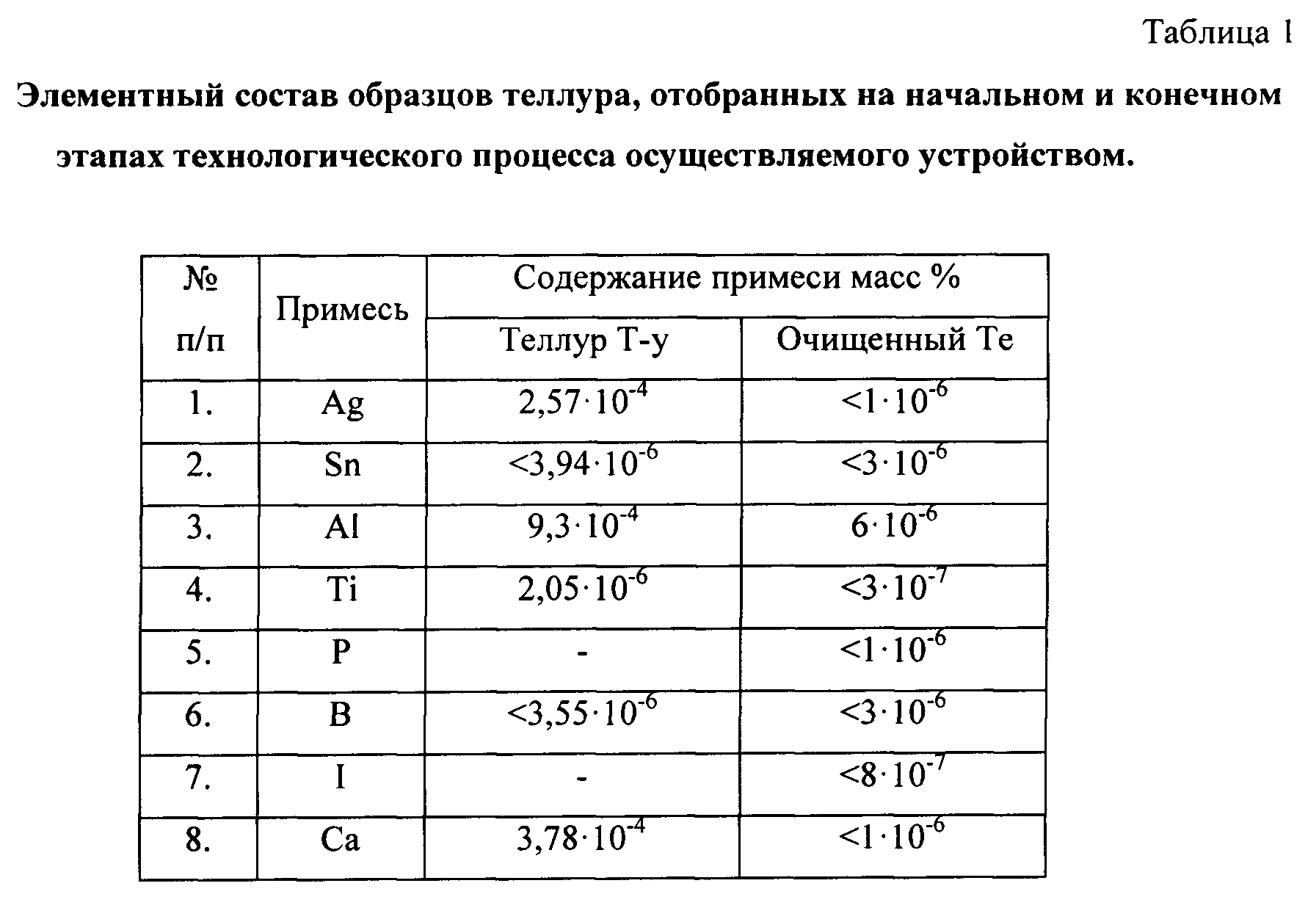
Технологические пробы материала отбирали на входной контроль и на готовую продукцию. Пробы подготавливали и отправляли на исследования элементного состава. Элементный анализ осуществляли масс-спектральными методами на двух площадках: Испытательном центре АО «Гиредмет» методом искровой масс-спектрометрии на масс-спектрометре с двойной фокусировкой JMS-01-BM2, производства фирмы JEOL; ООО «АРМОЛЕД» на масс-спектрометре с индуктивно связанной плазмой NexION. Результаты анализа представлены в таблице. В таблице указан состав примесей определенных как функциональный (в соответствии с литературными данными), для целей получения монокристаллов CdZnTe, CdTe, для детекторных элементов.Technological samples of the material were taken for input control and for finished products. Samples were prepared and sent for elemental composition studies. Elemental analysis was carried out by mass spectral methods at two sites: at the Testing Center of Giredmet JSC by spark mass spectrometry on a JMS-01-BM2 double-focusing mass spectrometer manufactured by JEOL; LLC "ARMOLED" on the mass spectrometer with inductively coupled plasma NexION. The results of the analysis are presented in the table. The table shows the composition of impurities defined as functional (in accordance with the literature data), for the purpose of obtaining CdZnTe, CdTe single crystals, for detector elements.

Ссылки по текстуText links
1. Пат. 2687403 РФ Кл. С01В 19/02 С22В 9/04 Способ получения высокочистого теллура методом дистилляции с пониженным содержанием селена / Гришечкин М.Б., Хомяков А.В., Можевитова Е.Н., Аветисов И.Х.; заявка: 2018135262, 08.10.2018, опубл.: 13.05.2019, Бюл. №14.1. Pat. 2687403 RF Cl. С01В 19/02
2. Высокочистые вещества. Коллектив авторов / Под ред. М.Ф. Чурбанова, Ю.А. Карпова, П.В. Зломанова, В.А. Федоров М.: Научный мир, 2018. - 994 с.2. High-purity substances. Team of authors / Ed. M.F. Churbanova, Yu.A. Karpova, P.V. Zlomanova, V.A. Fedorov M.: Scientific world, 2018. - 994 p.
Claims (11)
Publications (1)
| Publication Number | Publication Date |
|---|---|
| RU2777064C1 true RU2777064C1 (en) | 2022-08-01 |
Family
ID=
Cited By (2)
| Publication number | Priority date | Publication date | Assignee | Title |
|---|---|---|---|---|
| US12315650B2 (en) | 2023-04-04 | 2025-05-27 | CVF International LLC | Separation of rare earth elements by means of physical chemistry |
| RU2852018C1 (en) * | 2025-05-29 | 2025-12-02 | Общество с ограниченной ответственностью "АЛЛОЙТЕК" (ООО "АЛЛОЙТЕК") | Device for deep purification of metals |
Citations (3)
| Publication number | Priority date | Publication date | Assignee | Title |
|---|---|---|---|---|
| US6805833B2 (en) * | 2002-01-30 | 2004-10-19 | Dowa Mining Co., Ltd. | Apparatus for enhanced purification of high-purity metals |
| RU2687403C1 (en) * | 2018-10-08 | 2019-05-13 | Федеральное государственное бюджетное образовательное учреждение высшего образования "Российский химико-технологический университет имени Д.И. Менделеева" (РХТУ им. Д.И. Менделеева) | Method for producing high-purity tellure by distillation with low content of selenium |
| RU2706611C1 (en) * | 2019-04-01 | 2019-11-19 | Федеральное государственное бюджетное учреждение науки Институт химии высокочистых веществ им. Г.Г. Девятых Российской академии наук (ИХВВ РАН) | Method of producing especially pure selenium |
Patent Citations (3)
| Publication number | Priority date | Publication date | Assignee | Title |
|---|---|---|---|---|
| US6805833B2 (en) * | 2002-01-30 | 2004-10-19 | Dowa Mining Co., Ltd. | Apparatus for enhanced purification of high-purity metals |
| RU2687403C1 (en) * | 2018-10-08 | 2019-05-13 | Федеральное государственное бюджетное образовательное учреждение высшего образования "Российский химико-технологический университет имени Д.И. Менделеева" (РХТУ им. Д.И. Менделеева) | Method for producing high-purity tellure by distillation with low content of selenium |
| RU2706611C1 (en) * | 2019-04-01 | 2019-11-19 | Федеральное государственное бюджетное учреждение науки Институт химии высокочистых веществ им. Г.Г. Девятых Российской академии наук (ИХВВ РАН) | Method of producing especially pure selenium |
Cited By (2)
| Publication number | Priority date | Publication date | Assignee | Title |
|---|---|---|---|---|
| US12315650B2 (en) | 2023-04-04 | 2025-05-27 | CVF International LLC | Separation of rare earth elements by means of physical chemistry |
| RU2852018C1 (en) * | 2025-05-29 | 2025-12-02 | Общество с ограниченной ответственностью "АЛЛОЙТЕК" (ООО "АЛЛОЙТЕК") | Device for deep purification of metals |
Similar Documents
| Publication | Publication Date | Title |
|---|---|---|
| CN1032318C (en) | Method for growing multiple single crystals and apparatus for use threin | |
| US7976776B2 (en) | Mercury dispensing compositions and manufacturing process thereof | |
| EP1099770B1 (en) | Refining process for high purity gallium for producing compound semiconductor and apparatus for the same | |
| US3012865A (en) | Silicon purification process | |
| EP2810920B1 (en) | Device and method for refining silicon | |
| EP1335032B1 (en) | Vacuum distillation method and apparatus for enhanced purification of high-purity metals like indium | |
| RU2777064C1 (en) | Apparatus for deep purification of metals | |
| RU2776574C1 (en) | Method for deep cleaning of metals | |
| JP3842851B2 (en) | Indium purification method | |
| US3650823A (en) | Method for processing semiconductors | |
| CN111876619A (en) | Aluminum alloy melt refining treatment device and method for obtaining ultralow hydrogen and slag content | |
| US4518421A (en) | Process for producing solid metal particles from a bath of metal | |
| US3692294A (en) | Apparatus for production of zirconium metal | |
| RU2852018C1 (en) | Device for deep purification of metals | |
| JP2024528751A (en) | Apparatus and method for vacuum purification of selenium residues | |
| RU2852850C1 (en) | Method for deep purification of substances | |
| JPH06108175A (en) | Refining method for crude zinc and its device | |
| JPH01108322A (en) | Distillation refining process | |
| JPH10121162A (en) | Production of high-purity antimony and production device | |
| Abryutin et al. | Profound purification of tellurium, zinc and cadmium for electronic applications | |
| US3677742A (en) | Process for increasing the percentage of aluminum in aluminum-manganese alloys | |
| CN117259732A (en) | A high-purity material melting and sedimentation centrifugal preparation device | |
| US2960397A (en) | Separation of calcium metal from contaminants | |
| CN113649531B (en) | Production method of 5N zinc ingot | |
| US2474979A (en) | Process for the extraction of tin from iron alloys |