RU2772503C1 - Underwater reconfigurable modular robot - Google Patents
Underwater reconfigurable modular robot Download PDFInfo
- Publication number
- RU2772503C1 RU2772503C1 RU2022101615A RU2022101615A RU2772503C1 RU 2772503 C1 RU2772503 C1 RU 2772503C1 RU 2022101615 A RU2022101615 A RU 2022101615A RU 2022101615 A RU2022101615 A RU 2022101615A RU 2772503 C1 RU2772503 C1 RU 2772503C1
- Authority
- RU
- Russia
- Prior art keywords
- modules
- traction
- robot
- module
- underwater
- Prior art date
Links
- 230000033001 locomotion Effects 0.000 abstract description 15
- 238000004519 manufacturing process Methods 0.000 abstract description 4
- 239000000126 substance Substances 0.000 abstract 1
- 230000008859 change Effects 0.000 description 3
- 230000009466 transformation Effects 0.000 description 3
- WYTGDNHDOZPMIW-RCBQFDQVSA-N alstonine Natural products C1=CC2=C3C=CC=CC3=NC2=C2N1C[C@H]1[C@H](C)OC=C(C(=O)OC)[C@H]1C2 WYTGDNHDOZPMIW-RCBQFDQVSA-N 0.000 description 2
- 238000006073 displacement reaction Methods 0.000 description 2
- XLYOFNOQVPJJNP-UHFFFAOYSA-N water Substances O XLYOFNOQVPJJNP-UHFFFAOYSA-N 0.000 description 2
- 241000270295 Serpentes Species 0.000 description 1
- 238000005452 bending Methods 0.000 description 1
- 230000008901 benefit Effects 0.000 description 1
- 230000005484 gravity Effects 0.000 description 1
- 238000003032 molecular docking Methods 0.000 description 1
- 230000008520 organization Effects 0.000 description 1
- 229920003023 plastic Polymers 0.000 description 1
- 230000007704 transition Effects 0.000 description 1
Images
Abstract
Description
Изобретение относится к области мобильной робототехники, а именно к подводным роботам.The invention relates to the field of mobile robotics, namely to underwater robots.
Известен амфибийный змееподобный робот по патенту CN №101746237, который представляет собой устройство, исполненное в виде змеи и обладающее амфибийными свойствами. Робот состоит из последовательно соединенных модулей с возможностью поворота смежных модулей относительно друг друга в двух плоскостях путем изменения углов рыскания и тангажа. Соединения модулей защищены водонепроницаемой растяжимой оболочкой. Оба концевых модуля робота защищены прозрачной пластиковой купольной крышкой.Known amphibious serpentine robot patent CN No. 101746237, which is a device made in the form of a snake and has amphibious properties. The robot consists of series-connected modules with the ability to rotate adjacent modules relative to each other in two planes by changing the yaw and pitch angles. Module connections are protected by a waterproof tensile sheath. Both end modules of the robot are protected by a transparent plastic dome cover.
Известно многозвенное транспортное средство по патенту RU№130916 ПМ. Полезная модель относится к транспортным средствам, способным передвигаться по поверхности различных сред, внутри труб или под водой. Транспортное средство содержит сочлененные между собой с возможностью углового смещения относительно друг друга звенья в виде полых цилиндров, конструкция которых обеспечивает отклонение их относительно друг друга в горизонтальной и вертикальной плоскостях, а также по отношению к головной части и хвостовой на определенные углы. Соединительные элементы устройства выполнены из двух шарнирно соединенных между собой частей.Known multi-link vehicle according to patent RU№130916 PM. The utility model relates to vehicles capable of moving on the surface of various media, inside pipes or under water. The vehicle contains links in the form of hollow cylinders articulated with each other with the possibility of angular displacement relative to each other, the design of which ensures their deviation relative to each other in the horizontal and vertical planes, as well as in relation to the head and tail sections at certain angles. The connecting elements of the device are made of two hinged parts.
Известны змееподобные подводные роботы такие как, например, по патентам CN №204149158, CN №103358305, CN №106346462, CN №105171722, которые используют аналогичные приведенным выше принципы организации движения и обладают рядом похожих особенностей их конструктивного исполнения.Known snake-like underwater robots such as, for example, according to patents CN No. 204149158, CN No. 103358305, CN No. 106346462, CN No. 105171722, which use the principles of movement organization similar to the above and have a number of similar features of their design.
Все приведенные выше подводные змееподобные роботы обладают рядом схожих недостатков. А именно, 1) конструктивная сложность реализации управляемого универсального шарнира в ограниченном объеме обуславливает ограниченность диапазонов угловых перемещений шарниров, особенно это относится к двухстепенным шарнирам, 2) для организации плавного движения, подобного змеевидному необходимо в состав робота включать большое число модулей, согласованное управление которыми для целенаправленного движения робота под водой представляет собой сложную задачу, которая в условиях неопределенности параметров подвижной среды многократно затрудняется, 3) энергозатратность одновременного вращения приводами шарниров для создания волнообразного движения робота отрицательно сказывается на длительности его автономной работы.All of the above underwater snake-like robots have a number of similar disadvantages. Namely, 1) the design complexity of the implementation of a controlled universal joint in a limited volume determines the limited range of angular displacements of the joints, especially for two-degree joints, 2) to organize a smooth movement similar to a serpentine one, it is necessary to include a large number of modules in the robot, the coordinated control of which for purposeful movement of the robot under water is a complex task, which, under the conditions of uncertainty of the parameters of the moving medium, is many times more difficult;
В качестве прототипа выбран подводный робот по патенту US №2018021945, который содержит набор модулей-звеньев, соединенных друг с другом соединительными модулями для изменения формы робота с целью реализации изгибного движения робота, и несущих несколько тяговых (упорных) устройств, при этом, одно из тяговых устройств, установленное на одном из концов робота, создает усилие вдоль оси робота для обеспечения продольного движения робота, а другие тяговые устройства размещены в тяговых модулях стационарно попарно и создают перпендикулярные друг другу и оси модуля тяговые усилия, предназначенные для управления направлением движения. Модули-звенья также могут оснащаться разного рода полезной нагрузкой, например, ТВ камерами и/или неким инструментом. Такая структура робота позволяет произвольно изменять форму робота и при необходимости фиксировать ее, т.е. реконфигурировать робот, а с помощью тяговых устройств, установленных на тяговых модулях, которые определенным образом распределены и сориентированы по длине робота, предполагается осуществлять направленное движение робота и управление перемещением и ориентацией рабочего инструмента.As a prototype, an underwater robot was chosen according to US patent No. 2018021945, which contains a set of modules-links connected to each other by connecting modules to change the shape of the robot in order to implement the bending movement of the robot, and carrying several traction (thrust) devices, while one of traction devices installed at one of the ends of the robot creates a force along the axis of the robot to ensure the longitudinal movement of the robot, and other traction devices are placed in the traction modules in stationary pairs and create traction forces perpendicular to each other and the axis of the module, designed to control the direction of movement. Link modules can also be equipped with various kinds of payload, for example, TV cameras and / or some kind of tool. This structure of the robot allows you to arbitrarily change the shape of the robot and, if necessary, fix it, i.e. reconfigure the robot, and with the help of traction devices installed on traction modules, which are distributed and oriented in a certain way along the length of the robot, it is supposed to carry out the directed movement of the robot and control the movement and orientation of the working tool.
Прототипу присущи недостатки, выявленные у чисто змееподобных подводных роботов, связанные с реализацией волнообразного принципа движения. В тоже время наличие ряда тяговых модулей, на одном из которых жестко установлено одно осевое тяговое устройство, а на других жестко установлены два поперечных тяговых устройства, при фиксированной взаимной ориентации тяговых модулей между собой в осевом направлении, задаваемой конструктивно при изготовлении и сборке робота, приводит, в ряде случаев, к принципиальной невозможности создания тяговыми устройствами требуемого воздействия (главного вектора сил и главного вектора моментов) для выполнения заданной функции по назначению, а именно, управляемого целенаправленного движения. Отмеченное обстоятельство существенно снижает эффективность практического применения данного робота.The prototype has inherent shortcomings identified in purely snake-like underwater robots associated with the implementation of the wave-like principle of movement. At the same time, the presence of a number of traction modules, on one of which one axial traction device is rigidly installed, and on the others two transverse traction devices are rigidly installed, with a fixed mutual orientation of the traction modules to each other in the axial direction, which is specified structurally during the manufacture and assembly of the robot, leads to , in some cases, to the fundamental impossibility of creating the required impact by traction devices (the main vector of forces and the main vector of moments) to perform a given function for its intended purpose, namely, controlled purposeful movement. The noted circumstance significantly reduces the efficiency of the practical application of this robot.
Задачей изобретения является обеспечение управляемости движения робота в любой конфигурации, повышение энергоэффективности системы тяговых модулей, упрощение конструкции модулей, операций изготовления и сборки робота в различных последовательностях соединения модулей и архитектуры системы управления роботом.The objective of the invention is to provide controllability of the movement of the robot in any configuration, increase the energy efficiency of the system of traction modules, simplify the design of the modules, the operations of manufacturing and assembling the robot in various sequences of connecting modules and the architecture of the robot control system.
Задача обеспечения управляемости движения робота в любой конфигурации решается следующим образом:The task of ensuring the controllability of the robot's movement in any configuration is solved as follows:
в состав робота включены тяговые модули, внешние корпуса которых выполнены в форме прямых круговых цилиндров с установленными на них парами тяговых устройств с регулируемой силой тяги, причем каждое тяговое устройство установлено на выходном валу размещенного внутри корпуса тягового модуля полнооборотного сервопривода, причем оси вращения поворотных сервоприводов перпендикулярны оси цилиндра тягового модуля, а направление усилия, создаваемого тяговым устройством, перпендикулярно оси вращения поворотных сервоприводов.the robot includes traction modules, the outer housings of which are made in the form of straight circular cylinders with pairs of traction devices installed on them with adjustable traction force, each traction device is installed on the output shaft of a full-turn servo drive located inside the traction module housing, and the rotation axes of rotary servo drives are perpendicular axis of the cylinder of the traction module, and the direction of the force generated by the traction device is perpendicular to the axis of rotation of the rotary servo drives.
Кроме того, управляемость улучшается путем обеспечения контролируемой плавучести и остойчивости робота за счет конструктивно задаваемой плавучести и остойчивости жестких узлов модулей.In addition, controllability is improved by providing controlled buoyancy and stability of the robot due to the structurally specified buoyancy and stability of rigid modules.
Задача повышения энергоэффективности решается путем снижения гидродинамических сил сопротивления за счет обеспечения замкнутости обтекаемого внешнего корпуса робота в любой конфигурации.The problem of increasing energy efficiency is solved by reducing the hydrodynamic drag forces by ensuring the closure of the streamlined outer body of the robot in any configuration.
Этой же цели служит оснащение каждого модуля управляющим контроллером, позволяющим обрабатывать сигналы от датчиков модуля и внешних устройств и формировать сигналы для управления приводами модуля.The same purpose is served by equipping each module with a control controller, which allows processing signals from the module's sensors and external devices and generating signals for controlling the module's drives.
Задача упрощения конструкции модулей, операций изготовления и сборки робота в различных последовательностях соединения модулей и архитектуры системы управления роботом решается за счет конструкции реконфигурирующих модулей на основе одностепенного цилиндрического шарнира вращения, минимизации номенклатуры модулей, используемых при сборке робота, универсализации модулей за счет универсальности механических и электрических интерфейсов модулей и объединения модулей в сеть путем подсоединения к общей шине данных.The task of simplifying the design of modules, the operations of manufacturing and assembling the robot in various sequences of connecting modules and the architecture of the robot control system is solved by designing reconfiguring modules based on a single-degree cylindrical hinge of rotation, minimizing the range of modules used in assembling the robot, universalizing modules due to the universality of mechanical and electrical interfaces of modules and combining modules into a network by connecting to a common data bus.
Сущность изобретения поясняется следующими рисунками и чертежами.The essence of the invention is illustrated by the following figures and drawings.
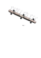
На фиг. 1 показан подводный реконфигурируемый модульный робот в конфигурации «торпеда», аксонометрия.In FIG. 1 shows an underwater reconfigurable modular robot in a torpedo configuration, perspective view.
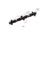
На фиг. 2 показан подводный реконфигурируемый модульный робот в конфигурации «торпеда» без внешних корпусов-обтекателей, аксонометрия.In FIG. 2 shows an underwater reconfigurable modular robot in a "torpedo" configuration without external fairings, perspective view.
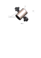
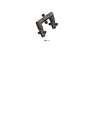
На фиг. 3 показан тяговый модуль с развернутыми тяговыми устройствами, аксонометрия.In FIG. 3 shows the traction module with the traction devices deployed, perspective view.
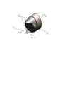
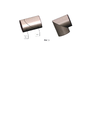
На фиг. 4 показан модуль продольной трансформации, аксонометрия.In FIG. 4 shows the longitudinal transformation module, perspective view.
На фиг. 5 показан модуль поперечной трансформации в двух конфигурациях.In FIG. 5 shows the transverse transformation module in two configurations.
На фиг. 6 показан подводный реконфигурируемый модульный робот в конфигурации «портал», аксонометрия.In FIG. 6 shows an underwater reconfigurable modular robot in a portal configuration, perspective view.
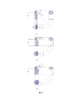
На фиг. 7 показаны три ортогональные проекции эллиптического цилиндра с полуосями а и b образующего эллипса, усеченного плоскостью под углом γ, а) γ<30°, б) γ=45°, с) γ=60°.In FIG. 7 shows three orthogonal projections of an elliptical cylinder with semi-axes a and b of the generating ellipse, truncated by a plane at an angle γ, a) γ<30°, b) γ=45°, c) γ=60°.
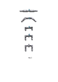
На фиг. 8 показан пример последовательности реконфигурации робота из положения «торпеда» в положение «портал».In FIG. Figure 8 shows an example of a robot reconfiguration sequence from the "torpedo" position to the "portal" position.
Подводный реконфигурируемый модульный робот включает в себя тяговые модули 1, реконфигурирующие продольные модули 2, реконфигурирующие поперечные модули 3, а также служебные модули 4, содержащие бортовую аппаратуру и оборудование, обеспечивающие функционирование робота по назначению. Внешние корпуса тяговых модулей 1 выполнены в форме прямых круговых цилиндров с установленными на внутреннем каркасе парами тяговых устройств 5 с регулируемой силой тяги, причем каждое тяговое устройство установлено на выходном валу 6 размещенного внутри корпуса тягового модуля полнооборотного сервопривода.The underwater reconfigurable modular robot includes
Реконфигурирующий продольный модуль 2, состоит из двух частей, связанных приводным одностепенным шарниром вращения, при этом продольные модули выполнены из двух частей 7, 8 с внешними корпусами в форме прямых цилиндров, в одной из которых 7 в отсеке внутреннего каркаса установлен полнооборотный сервопривод с осью вращения, совпадающей с осью цилиндра 9. В свою очередь, поперечный реконфигурирующий модуль выполнен из двух частей 10, 11 с внешними корпусами в форме прямых эллиптических цилиндров, усеченных проходящей под углом γ=arcsin(b/a) к их осям через большую ось образующего эллипса с большой а и малой Ь осями плоскостью, в одной из частей модуля 10 в отсеке внутреннего каркаса установлен полнооборотный сервопривод с осью вращения 12 (см фиг. 2), проходящей перпендикулярно плоскости через центр образованного кругового сечения с диаметром равным большой полуоси эллипса а. На фиг. 7 а, б, в схематично показаны примеры исполнения поперечных реконфигурирующих модулей с углами трансформации γ, равными 30°, 45° и 60°, с большой осью а равной 100 условным единицам и с малыми осями, соответственно, равными 50, 70, 71 и 86,6 условных единиц.The reconfiguring
Для обеспечения плавности обтекания робота внешний корпус приводной части продольного модуля 7 также имеет эллиптическое сечение с большой а и малой b осями для стыковки с поперечными модулями, а внешний корпус второй части продольного модуля 8 и внешний корпус тягового модуля 1 имеют диаметры равные малой оси эллипса b, при этом на внешнем корпусе 7 установлены согласующие обтекатели 13.To ensure smooth flow around the robot, the outer casing of the drive part of the longitudinal module 7 also has an elliptical section with major a and minor b axes for docking with transverse modules, and the outer casing of the second part of the
Каждый модуль 1-4 имеет на основаниях корпусов механический и электрический интерфейс, позволяющий соединять модули в произвольном порядке. Герметичность электрических интерфейсов обеспечивается применением разъемов в герметичном исполнении.Each module 1-4 has a mechanical and electrical interface on the bases of the housings, allowing you to connect the modules in any order. The tightness of the electrical interfaces is ensured by the use of sealed connectors.
Служебные модули 4 для обеспечения функционирования робота могут оснащаться, например, телекамерами, осветителями под прозрачными колпаками-обтекателями, захватными устройствами, гидролокаторами, регистраторами физических полей, устройствами связи, дополнительными источниками питания, устройствами изменения плавучести, манипуляторами и т.д.
Подводный реконфигурируемый модульный робот работает следующим образом.Underwater reconfigurable modular robot works as follows.
Из модулей с использованием механических и электрических интерфейсов собирается в выбранном порядке желаемая конфигурация, например, конфигурация «торпеда» с соосным расположением модулей, как показано на Фиг. 2. Далее на внутренние корпуса устанавливаются обтекатели (см. Фиг. 1).From the modules using mechanical and electrical interfaces, the desired configuration is assembled in a selected order, for example, a “torpedo” configuration with coaxial arrangement of modules, as shown in Fig. 2. Next, fairings are installed on the inner hulls (see Fig. 1).
В этой конфигурации подводный робот может выполнять движение по задаваемому заранее или определяемому системой управления робота пространственному маршруту в пункт назначения. Для перемещения по маршруту робот использует винтовые тяговые устройства - импеллеры с управляемой ориентацией тяги за счет поворотов импеллеров сервоприводами тяговых модулей и регулирования силы тяги за счет скорости вращения самих винтов.In this configuration, the underwater robot can move along a predetermined or determined by the robot's control system spatial route to the destination. To move along the route, the robot uses screw traction devices - impellers with controlled thrust orientation due to the rotation of the impellers by the servo drives of the traction modules and the regulation of the traction force due to the speed of rotation of the screws themselves.
Для выполнения операций маневрирования вблизи объектов или в сложном рельефе робот может быть реконфигурирован с помощью модулей реконфигурации в конфигурацию, например, «портал» (см. Фиг. 8). Преимущество конфигурации «портал» состоит в возможности получить большее расстояние между центром давления и центром масс робота. Это обеспечивает лучшую остойчивость, меньшую частоту свободных колебаний. Управление перемещениями робота после перехода в конфигурацию «портал» выполняется с помощью регулирования тяги импеллеров и направления их осей. При необходимости для получения желаемого качества управления перемещением могут быть использованы также и приводы модулей реконфигурации.To perform maneuvering operations near objects or in difficult terrain, the robot can be reconfigured using reconfiguration modules into a configuration, for example, a "portal" (see Fig. 8). The advantage of the "gantry" configuration is the possibility of obtaining a greater distance between the center of pressure and the center of gravity of the robot. This provides better stability, lower frequency of free vibrations. The movement of the robot after the transition to the "portal" configuration is controlled by adjusting the thrust of the impellers and the direction of their axes. If necessary, the drives of the reconfiguration modules can also be used to obtain the desired quality of motion control.
Claims (5)
Publications (1)
| Publication Number | Publication Date |
|---|---|
| RU2772503C1 true RU2772503C1 (en) | 2022-05-23 |
Family
ID=
Cited By (3)
| Publication number | Priority date | Publication date | Assignee | Title |
|---|---|---|---|---|
| CN115285327A (en) * | 2022-08-19 | 2022-11-04 | 杭州电子科技大学 | Creative splicing and assembling underwater robot module and splicing and assembling method thereof |
| CN118144963A (en) * | 2024-05-07 | 2024-06-07 | 青岛哈尔滨工程大学创新发展中心 | Butt joint locking module with double locking function and separated underwater butt joint robot |
| CN120986637A (en) * | 2025-08-29 | 2025-11-21 | 辽宁大学 | High-reliability splitting and rejoining mechanism and its control method for autonomous reconfiguration of underwater robots |
Citations (8)
| Publication number | Priority date | Publication date | Assignee | Title |
|---|---|---|---|---|
| CN201342916Y (en) * | 2008-12-19 | 2009-11-11 | 中国科学院沈阳自动化研究所 | Amphibious snake-shaped robot |
| RU130916U1 (en) * | 2013-05-23 | 2013-08-10 | Федеральное государственное бюджетное учреждение науки Институт проблем механики им. А.Ю. Ишлинского Российской академии наук (ИПМех РАН) | MULTI-STANDARD VEHICLE |
| CN103358305A (en) * | 2013-06-17 | 2013-10-23 | 西安电子科技大学 | Closed-loop control available multifunctional in-water snake-shaped robot |
| CN105171722A (en) * | 2015-10-26 | 2015-12-23 | 冯亿坤 | Eel-like underwater multi-freedom-degree robot |
| CN105313110A (en) * | 2014-07-16 | 2016-02-10 | 中国科学院沈阳自动化研究所 | Underwater gliding snakelike robot |
| WO2016120071A1 (en) * | 2015-01-29 | 2016-08-04 | Norwegian University Of Science And Technology (Ntnu) | Underwater manipulator arm robot |
| CN106346462A (en) * | 2016-09-19 | 2017-01-25 | 哈尔滨工业大学深圳研究生院 | Snake-like amphibious robot provided with modular joints |
| WO2021170855A1 (en) * | 2020-02-28 | 2021-09-02 | Rosen Swiss Ag | Modular underwater vehicle having modules that are orientable with respect to one another |
Patent Citations (8)
| Publication number | Priority date | Publication date | Assignee | Title |
|---|---|---|---|---|
| CN201342916Y (en) * | 2008-12-19 | 2009-11-11 | 中国科学院沈阳自动化研究所 | Amphibious snake-shaped robot |
| RU130916U1 (en) * | 2013-05-23 | 2013-08-10 | Федеральное государственное бюджетное учреждение науки Институт проблем механики им. А.Ю. Ишлинского Российской академии наук (ИПМех РАН) | MULTI-STANDARD VEHICLE |
| CN103358305A (en) * | 2013-06-17 | 2013-10-23 | 西安电子科技大学 | Closed-loop control available multifunctional in-water snake-shaped robot |
| CN105313110A (en) * | 2014-07-16 | 2016-02-10 | 中国科学院沈阳自动化研究所 | Underwater gliding snakelike robot |
| WO2016120071A1 (en) * | 2015-01-29 | 2016-08-04 | Norwegian University Of Science And Technology (Ntnu) | Underwater manipulator arm robot |
| CN105171722A (en) * | 2015-10-26 | 2015-12-23 | 冯亿坤 | Eel-like underwater multi-freedom-degree robot |
| CN106346462A (en) * | 2016-09-19 | 2017-01-25 | 哈尔滨工业大学深圳研究生院 | Snake-like amphibious robot provided with modular joints |
| WO2021170855A1 (en) * | 2020-02-28 | 2021-09-02 | Rosen Swiss Ag | Modular underwater vehicle having modules that are orientable with respect to one another |
Cited By (3)
| Publication number | Priority date | Publication date | Assignee | Title |
|---|---|---|---|---|
| CN115285327A (en) * | 2022-08-19 | 2022-11-04 | 杭州电子科技大学 | Creative splicing and assembling underwater robot module and splicing and assembling method thereof |
| CN118144963A (en) * | 2024-05-07 | 2024-06-07 | 青岛哈尔滨工程大学创新发展中心 | Butt joint locking module with double locking function and separated underwater butt joint robot |
| CN120986637A (en) * | 2025-08-29 | 2025-11-21 | 辽宁大学 | High-reliability splitting and rejoining mechanism and its control method for autonomous reconfiguration of underwater robots |
Similar Documents
| Publication | Publication Date | Title |
|---|---|---|
| CN111746764B (en) | Biological heuristic underwater robot | |
| Luo et al. | OriSnake: Design, fabrication, and experimental analysis of a 3-D origami snake robot | |
| US3712481A (en) | Actuator | |
| CN113232804A (en) | Modular underwater snake-shaped robot | |
| Yang et al. | The snake-inspired robots: a review | |
| Guo et al. | Development of an amphibious mother spherical robot used as the carrier for underwater microrobots | |
| Zhang et al. | Development of a low-cost flexible modular robot GZ-I | |
| CN115723926A (en) | An underwater snake-like robot with adjustable center of gravity | |
| CN114460950A (en) | Self-reconfigurable cell star device | |
| Li et al. | Hydrodynamic analysis and motion control of the Coanda-effect jet thruster for underwater robots | |
| RU2772503C1 (en) | Underwater reconfigurable modular robot | |
| Lyu et al. | A snake eel inspired multi-joint underwater inspection robot for undersea infrastructure intelligent maintenance | |
| CN113734390A (en) | Flexible body wave fin underwater robot | |
| CN212605739U (en) | Hay ray robot | |
| Pagliai et al. | Design of a reconfigurable autonomous underwater vehicle for offshore platform monitoring and intervention | |
| CN112660345A (en) | Six-degree-of-freedom underwater detection robot | |
| CN110406652B (en) | Two-degree-of-freedom joint for deep-sea multi-joint submersible vehicle | |
| CN113148079A (en) | Autonomous navigation mechanical arm for underwater operation | |
| Bauschmann et al. | Towards full actuation: reconfigurable micro underwater robots | |
| Truong et al. | Design and characterization of a fully autonomous under-actuated soft batoid-like robot | |
| CN113296524A (en) | Thrust vector distribution optimization method for underwater bionic spherical/hemispherical robot | |
| CN118343279A (en) | An underwater super-redundant robotic moray eel | |
| Sourkounis et al. | Exploring the deep sea: Combining a bistable mechanism with origami-inspired soft actuators | |
| CN116873166A (en) | An underwater bionic flexible multifunctional resident robot, system and control method | |
| Hu et al. | Modular design and motion control of reconfigurable robotic fish |