RU2771993C2 - Electric machine with rotor created according to halbach scheme - Google Patents
Electric machine with rotor created according to halbach scheme Download PDFInfo
- Publication number
- RU2771993C2 RU2771993C2 RU2020133981A RU2020133981A RU2771993C2 RU 2771993 C2 RU2771993 C2 RU 2771993C2 RU 2020133981 A RU2020133981 A RU 2020133981A RU 2020133981 A RU2020133981 A RU 2020133981A RU 2771993 C2 RU2771993 C2 RU 2771993C2
- Authority
- RU
- Russia
- Prior art keywords
- magnets
- halbach
- rotor
- tangent
- respect
- Prior art date
Links
- 230000005415 magnetization Effects 0.000 claims abstract description 21
- 238000004804 winding Methods 0.000 claims abstract description 20
- 230000005291 magnetic Effects 0.000 claims abstract description 13
- 230000004907 flux Effects 0.000 claims abstract description 7
- 239000003302 ferromagnetic material Substances 0.000 claims abstract description 5
- 125000004122 cyclic group Chemical group 0.000 claims abstract description 4
- 230000005294 ferromagnetic Effects 0.000 claims abstract description 4
- 230000005355 Hall effect Effects 0.000 claims description 2
- 238000004870 electrical engineering Methods 0.000 abstract description 2
- 239000000126 substance Substances 0.000 abstract 1
- 230000001939 inductive effect Effects 0.000 description 4
- 230000001360 synchronised Effects 0.000 description 3
- 239000000463 material Substances 0.000 description 2
- 230000035699 permeability Effects 0.000 description 2
- 241000282326 Felis catus Species 0.000 description 1
- 239000004020 conductor Substances 0.000 description 1
Images

Abstract
Description
Изобретение относится к электротехнике, в частности к синхронным электрическим машинам с мультинаправленным вектором намагниченности постоянных магнитов, и может быть использовано для двигателей и генераторов с ротором, созданным по схеме Хальбаха.The invention relates to electrical engineering, in particular to synchronous electric machines with a multidirectional magnetization vector of permanent magnets, and can be used for motors and generators with a Halbach rotor.
Известен Электромеханический преобразователь (патент на изобретение РФ №2302692, МГЖ Н02K 19/10), содержащий, по меньшей мере, одну статорно-роторную пару, в которой статор состоит из сердечников из материала с высокой магнитной проницаемостью, торцами прикрепленных к опорному статорному кольцу и ориентированных параллельно основному магнитному потоку, и между которыми расположены проводники многофазной обмотки, ротор выполнен в виде двух коаксиально расположенных наружного и внутреннего индукторов - магнитопроводов из материала с высокой магнитной проницаемостью в форме полых цилиндров, закрепленных с возможностью вращения относительно статора, несущих расположенные по окружностям полюса с чередующейся полярностью, обращенные через рабочие зазоры к статору и охватывающие его, при этом полярность полюсов, расположенных на внутреннем и наружном индукторах друг напротив друга, согласная, отличающийся тем, что число полюсов 2⋅р, число пар полюсов р, число сердечников статора z и число катушечных групп в фазе d связаны соотношениями:Known Electromechanical converter (patent for the invention of the Russian Federation No. 2302692, MGZH H02K 19/10), containing at least one stator-rotor pair, in which the stator consists of cores of a material with high magnetic permeability, the ends attached to the support stator ring and oriented parallel to the main magnetic flux, and between which the conductors of the multiphase winding are located, the rotor is made in the form of two coaxially located external and internal inductors - magnetic cores made of a material with high magnetic permeability in the form of hollow cylinders, fixed for rotation relative to the stator, bearing poles located along the circles with alternating polarity, facing through the working gaps to the stator and covering it, while the polarity of the poles located on the inner and outer inductors opposite each other, consonant, characterized in that the number of poles is 2⋅p, the number of pairs of poles p, the number of stator cores z and number of cat ear groups in phase d are related by the relations:
![]()
![]()
где: k=1, 1,5, 2, 2.5, 3, 3.5… - целое положительное число, или число, отличающееся от него на 0.5, при этом, если k - целое число, обмотки катушечных групп в каждой фазе соединены согласно, а при k - отличном от целого числа на 0.5 и d равно четному числу (2, 4, 6…) обмотки катушечных групп в каждой фазе соединены встречно иwhere: k=1, 1.5, 2, 2.5, 3, 3.5… is a positive integer, or a number that differs from it by 0.5, while if k is an integer, the windings of the coil groups in each phase are connected according to, and when k is different from an integer by 0.5 and d is equal to an even number (2, 4, 6 ...), the windings of the coil groups in each phase are connected in opposite directions and
![]()
![]()
и при этомand wherein
z/(2⋅p) ≠ 1.z/(2⋅p) ≠ 1.
Характеристики патента-аналога нуждаются в улучшении за счет использования схемы Хальбаха расположения векторов намагниченности постоянных магнитов его индукторов. Необходимо также обеспечить правильный момент включения фаз якоря за счет использования датчиков положения ротора.The characteristics of the patent analogue need to be improved by using the Halbach scheme for the arrangement of the magnetization vectors of the permanent magnets of its inductors. It is also necessary to ensure the correct moment of switching on the armature phases through the use of rotor position sensors.
Известна принятая в качестве прототипа Электромашина с ротором, созданным по схеме Хальбаха (патент на изобретение РФ №2720233, МПК Н02K 21/12), содержащая узел обмотки, состоящий из множества катушек, причем множество катушек расположены в форме кольца, и ротор, включающий в себя множество внешних магнитов, выполненных в виде внешнего кольца Хальбаха, окружающий обмотку в сборе; корпус внешних магнитов, соединенный с множеством внешних магнитов, причем корпус внешних магнитов окружает множество внешних магнитов; множество внутренних магнитов, выполненных в виде внутреннего кольца Хальбаха, причем, обмотка расположена между множеством внутренних магнитов и множеством внешних магнитов; корпус внутренних магнитов, соединенный с множеством внутренних магнитов; выходной вал, соединенный с внутренним корпусом магнитов, отличающаяся тем, что внешнее кольцо Хальбаха ротора собрано из магнитов с цикличным повторением следующей последовательности направления вектора намагниченности постоянных магнитов (на их торцевой поверхности): тангенциально, против часовой стрелки; радиально от центра; тангенциально, по часовой стрелке; радиально к центру; во внутреннем кольце Хальбаха циклично повторяются следующие направления вектора намагниченности: тангенциально, по часовой стрелке; радиально от центра; тангенциально, против часовой стрелки; радиально к центру, а направление намагниченности на внутреннем и внешнем кольцах Хальбаха согласованы так, чтобы магнитный поток, созданный постоянными магнитами внутреннего и внешнего колец, складывался; с внешней стороны внешнего кольца Хальбаха расположено ярмо из ферромагнитного материала, с внутренней стороны внутреннего кольца Хальбаха расположено ярмо из ферромагнитного материала, магниты закреплены на ярмах, в обмотке отсутствуют ферромагнитные элементы.Known adopted as a prototype Electric machine with a rotor created according to the Halbach scheme (patent for the invention of the Russian Federation No. itself a plurality of external magnets, made in the form of an outer Halbach ring, surrounding the winding assembly; an external magnet housing connected to a plurality of external magnets, the external magnet housing surrounding the plurality of external magnets; a plurality of internal magnets in the form of an internal Halbach ring, wherein the winding is located between the plurality of internal magnets and the plurality of external magnets; an internal magnet housing connected to a plurality of internal magnets; an output shaft connected to the inner housing of the magnets, characterized in that the outer Halbach ring of the rotor is assembled from magnets with a cyclic repetition of the following sequence of the direction of the magnetization vector of the permanent magnets (on their end surface): tangentially, counterclockwise; radially from the center; tangentially, clockwise; radially towards the center; in the inner Halbach ring, the following directions of the magnetization vector are cyclically repeated: tangentially, clockwise; radially from the center; tangentially, counterclockwise; radially to the center, and the direction of magnetization on the inner and outer Halbach rings are coordinated so that the magnetic flux created by the permanent magnets of the inner and outer rings is added; on the outer side of the outer Halbach ring there is a yoke of ferromagnetic material, on the inner side of the inner Halbach ring there is a yoke of ferromagnetic material, the magnets are fixed on the yokes, there are no ferromagnetic elements in the winding.
Недостатком прототипа является то, что в нем невозможно достичь высокой плотности тока якоря из-за того, что катушки обмотки якоря расположены в форме кольца. В результате, электромагнитный и вращающий моменты такой машины в режиме двигателя - невелики, удельная мощность в режиме генератора также невелика. Кроме того, распределение магнитной индукции в воздушных зазорах - несинусоидально, что приводит к снижению КПД и росту добавочных потерь.The disadvantage of the prototype is that it is impossible to achieve a high armature current density due to the fact that the armature winding coils are arranged in the form of a ring. As a result, the electromagnetic and torque moments of such a machine in the engine mode are small, and the specific power in the generator mode is also small. In addition, the distribution of magnetic induction in the air gaps is non-sinusoidal, which leads to a decrease in efficiency and an increase in additional losses.
Объектом изобретения является синхронная электрическая машина, включающая в свой состав статор из отдельных ферромагнитных зубцов, зубцовой обмотки, укомплектованный датчиками положения ротора, а также ротор, имеющий два индуктора с постоянными магнитами, намагниченными по специальной схеме Хальбаха.The object of the invention is a synchronous electric machine, which includes a stator of individual ferromagnetic teeth, a tooth winding, equipped with rotor position sensors, as well as a rotor having two inductors with permanent magnets magnetized according to a special Halbach scheme.
Технической задачей, решаемой изобретением, является максимизация КПД (во всех режимах), а также электромагнитного момента (в двигательном режиме) и удельной мощности (в генераторном режиме).The technical problem solved by the invention is to maximize efficiency (in all modes), as well as electromagnetic torque (in motor mode) and power density (in generator mode).
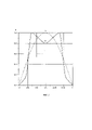
На фигуре 1 показано поперечное сечение активной части электрической машины с ротором, созданным по схеме Хальбаха, на фигуре 2 - распределение магнитной индукции в прототипе и в электрической машине, выполненной в соответствие с изобретением.Figure 1 shows a cross section of the active part of the electric machine with a rotor created according to the Halbach scheme, figure 2 shows the distribution of magnetic induction in the prototype and in the electric machine made in accordance with the invention.
Решение технической задачи обусловлено созданием статора (якоря), позволяющего увеличить плотность тока в якоре за счет размещения обмотки на зубцах, наличием ротора, охватывающего статор с внешней и внутренней стороны, в котором вектора намагниченности постоянных магнитов расположены по специальной схеме Хальбаха.The solution of the technical problem is due to the creation of a stator (armature), which makes it possible to increase the current density in the armature by placing the winding on the teeth, the presence of a rotor covering the stator from the outside and inside, in which the magnetization vectors of the permanent magnets are arranged according to a special Halbach scheme.
Техническая задача решается, согласно изобретению, совокупностью существенных признаков, представленных в п. 1 формулы.The technical problem is solved, according to the invention, by a combination of essential features presented in paragraph 1 of the formula.
Техническим результатом предложенного изобретения является электромашина, состоящая из ротора и статора (фиг. 1). Ротор, состоит из двух колец Хальбаха (внутреннего 1 и внешнего 2), в которых четко определены направления векторов намагниченности постоянных магнитов (показаны стрелками), а также включающий в свой состав внутреннее 3 и внешнее 4 ярма, на которых крепятся постоянные магниты внутреннего 1 и внешнего 2 колец Хальбаха. Схема Хальбаха определяет цикличное повторение следующей последовательности направления вектора намагниченности постоянных магнитов (на их торцевой поверхности) на внешнем кольце:The technical result of the proposed invention is an electric machine consisting of a rotor and a stator (Fig. 1). The rotor consists of two Halbach rings (internal 1 and external 2), in which the directions of the magnetization vectors of permanent magnets are clearly defined (shown by arrows), and also includes internal 3 and external 4 yokes, on which the permanent magnets of the internal 1 and outer 2 Halbach rings. The Halbach scheme determines the cyclic repetition of the following sequence of the direction of the magnetization vector of permanent magnets (on their end surface) on the outer ring:
- под 45° во внешнем направлении по часовой стрелке по отношению к касательной;- at 45° in the outer direction clockwise with respect to the tangent;
- тангенциально, по часовой стрелке;- tangentially, clockwise;
- под 45° в направлении во внутрь по часовой стрелке по отношению к касательной;- at 45° towards the inside, clockwise with respect to the tangent;
- радиально к центру;- radially to the center;
- под 45° в направлении во внутрь против часовой стрелки по отношению к касательной;- at 45 ° in the direction inward counterclockwise with respect to the tangent;
- тангенциально, против часовой стрелки;- tangentially, counterclockwise;
- под 45° во внешнем направлении против часовой стрелки по отношению к касательной;- at 45° in the outer direction counterclockwise with respect to the tangent;
- радиально от центра;- radially from the center;
на внутреннем кольце Хальбаха циклично повторяются следующие направления вектора намагниченности:on the inner Halbach ring, the following directions of the magnetization vector are cyclically repeated:
- под 45° во внешнем направлении против часовой стрелки по отношению к касательной;- at 45° in the outer direction counterclockwise with respect to the tangent;
- тангенциально, против часовой стрелки;- tangentially, counterclockwise;
- под 45° в направлении во внутрь против часовой стрелки по отношению к касательной;- at 45 ° in the direction inward counterclockwise with respect to the tangent;
- радиально к центру;- radially to the center;
- под 45° в направлении во внутрь по часовой стрелке по отношению к касательной;- at 45° towards the inside, clockwise with respect to the tangent;
- тангенциально, по часовой стрелке;- tangentially, clockwise;
- под 45° во внешнем направлении по часовой стрелке по отношению к касательной;- at 45° in the outer direction clockwise with respect to the tangent;
- радиально от центра;- radially from the center;
а направление намагниченности на внутреннем и внешнем кольцах Хальбаха согласованы так, чтобы магнитный поток, созданный постоянными магнитами внутреннего и внешнего колец, складывался. Кроме того, ширина постоянного магнита bm-rad с радиальным направлением намагниченности должна составлять половину полюсного деления τ:and the direction of magnetization on the inner and outer Halbach rings are matched so that the magnetic flux created by the permanent magnets of the inner and outer rings adds up. In addition, the width of the permanent magnet b m-rad with the radial direction of magnetization should be half the pole division τ:
bm-rad=τ/2,b m-rad =τ/2,
а ширина каждого постоянного магнита bm-τ с нерадиальным направлением намагниченности должна составлять:and the width of each permanent magnet b m-τ with a non-radial direction of magnetization should be:
bm-τ=τ/6.b m-τ =τ/6.
Описанные направления векторов намагниченности постоянных магнитов в сочетании с их согласованным расположением на внутреннем и внешнем кольцах Хальбаха позволяют получить суммирование магнитного потока от постоянных магнитов внутреннего 1 и внешнего 2 колец Хальбаха, а ярма - концентрацию магнитного потока в зоне обмотки 5 якоря, намотанной на зубцах 6 для достижения максимального электромагнитного момента (в двигательном режиме) и максимальной удельной мощности (в генераторном режиме) электрической машины при обеспечении необходимой плотности тока в обмотке 5. Обмотка 5 образует фазы А, В, С. На фиг. 1 обмотка соединена в звезду с нулевой шиной 0. Точками на фиг. 1 отмечены начала катушек обмотки 5. Поскольку под обмотку 5 отводится больше места, чем в прототипе, возможно обеспечение более высокой плотности тока, и таким образом, решение технической задачи.The described directions of the magnetization vectors of the permanent magnets in combination with their coordinated arrangement on the inner and outer Halbach rings make it possible to obtain the summation of the magnetic flux from the permanent magnets of the inner 1 and outer 2 Halbach rings, and the yoke - the concentration of the magnetic flux in the area of the winding 5 of the armature wound on the
Кроме того, описанные направления векторов намагниченности постоянных магнитов в сочетании с широной постоянных магнитов на внутреннем и внешнем кольцах Хальбаха позволяют получить близкое к синусоиде распределение магнитной индукции 7 в любом из воздушных зазоров по сравнению с прототипом 8 (фиг. 2). Это приводит к увеличению КПД и снижению добавочных потерь по сравнению с прототипом. Следует отметить, что на фиг. 2 по оси ординат отмечены относительные значения индукции, где максимальное значение принято за единицу.In addition, the described directions of the magnetization vectors of the permanent magnets in combination with the width of the permanent magnets on the inner and outer Halbach rings make it possible to obtain a distribution of
Для решения технической задачи в части обеспечения максимизации электромагнитного момента, между зубцами якоря расположены датчики положения ротора. Наиболее надежными являются датчики положения ротора, построенные с использованием эффекта Холла.To solve the technical problem in terms of ensuring the maximization of the electromagnetic moment, rotor position sensors are located between the armature teeth. The most reliable are rotor position sensors built using the Hall effect.
Принцип действия электромашины с ротором, созданным по схеме Хальбаха в целом соответствует принципу работы синхронных электрических машин переменного тока в двигательном и генераторном режимах.The principle of operation of an electric machine with a rotor created according to the Halbach scheme as a whole corresponds to the principle of operation of synchronous AC machines in motor and generator modes.
Claims (6)
Priority Applications (1)
| Application Number | Priority Date | Filing Date | Title |
|---|---|---|---|
| RU2020133981A RU2771993C2 (en) | 2020-10-15 | Electric machine with rotor created according to halbach scheme |
Applications Claiming Priority (1)
| Application Number | Priority Date | Filing Date | Title |
|---|---|---|---|
| RU2020133981A RU2771993C2 (en) | 2020-10-15 | Electric machine with rotor created according to halbach scheme |
Publications (3)
| Publication Number | Publication Date |
|---|---|
| RU2020133981A RU2020133981A (en) | 2022-04-15 |
| RU2020133981A3 RU2020133981A3 (en) | 2022-04-26 |
| RU2771993C2 true RU2771993C2 (en) | 2022-05-16 |
Family
ID=
Citations (5)
| Publication number | Priority date | Publication date | Assignee | Title |
|---|---|---|---|---|
| WO2006118219A1 (en) * | 2005-04-28 | 2006-11-09 | Denso Corporation | Motor and control device thereof |
| RU2015144966A (en) * | 2015-10-19 | 2017-04-25 | Валерий Петрович Бордыков | ELECTRIC MACHINE (OPTIONS) |
| WO2019115632A1 (en) * | 2017-12-13 | 2019-06-20 | Luxembourg Institute Of Science And Technology (List) | Compact halbach electrical generator for integration in a solid body |
| RU2720233C1 (en) * | 2019-12-23 | 2020-04-28 | Андрей Борисович Захаренко | Electric machine with rotor made as per halbach circuit |
| CN111541326A (en) * | 2020-05-18 | 2020-08-14 | 南京航空航天大学 | Halbach array magnetic gathering type permanent magnet memory motor |
Patent Citations (5)
| Publication number | Priority date | Publication date | Assignee | Title |
|---|---|---|---|---|
| WO2006118219A1 (en) * | 2005-04-28 | 2006-11-09 | Denso Corporation | Motor and control device thereof |
| RU2015144966A (en) * | 2015-10-19 | 2017-04-25 | Валерий Петрович Бордыков | ELECTRIC MACHINE (OPTIONS) |
| WO2019115632A1 (en) * | 2017-12-13 | 2019-06-20 | Luxembourg Institute Of Science And Technology (List) | Compact halbach electrical generator for integration in a solid body |
| RU2720233C1 (en) * | 2019-12-23 | 2020-04-28 | Андрей Борисович Захаренко | Electric machine with rotor made as per halbach circuit |
| CN111541326A (en) * | 2020-05-18 | 2020-08-14 | 南京航空航天大学 | Halbach array magnetic gathering type permanent magnet memory motor |
Similar Documents
| Publication | Publication Date | Title |
|---|---|---|
| KR100785276B1 (en) | Permanent magnet excited transverse flux motor with out-rotor | |
| CN107710569B (en) | Improved multi-channel electric motor/generator | |
| CN108964396B (en) | Stator partition type alternate pole hybrid excitation motor | |
| RU2720233C1 (en) | Electric machine with rotor made as per halbach circuit | |
| JP6327803B2 (en) | High-power, high-efficiency single-phase multipolar generator | |
| CN104821668A (en) | Novel stator permanent magnet type motor | |
| US3912958A (en) | Flux-switched inductor alternator | |
| TW201440389A (en) | High efficiency permanent magnet machine | |
| JP5907813B2 (en) | Brushless motor | |
| RU2356154C1 (en) | Electrical machine with double-pack inductor (versions) | |
| RU2719685C1 (en) | Electric motor stator | |
| RU2311715C1 (en) | Synchronous electrical machine | |
| US9831753B2 (en) | Switched reluctance permanent magnet motor | |
| KR101682408B1 (en) | Electric motor | |
| Fukami et al. | Magnet arrangement in novel flux-modulating synchronous machines with permanent magnet excitation | |
| RU2771993C2 (en) | Electric machine with rotor created according to halbach scheme | |
| JP2015512241A (en) | Electric machine | |
| RU2393615C1 (en) | Single-phase contact-free electromagnetic generator | |
| RU105540U1 (en) | MODULAR ELECTRIC MACHINE | |
| RU2716489C2 (en) | Electromechanical converter | |
| RU175895U9 (en) | RING WINDING ANCHOR ELECTRIC MACHINE | |
| RU2541427C1 (en) | Terminal electric machine (versions) | |
| EA008613B1 (en) | Polyphase electrical machine | |
| WO2009051515A1 (en) | Synchronous electrical machine | |
| EP2894772A1 (en) | Electromechanical converter |