RU2771663C1 - Device for the transmission of electric energy - Google Patents
Device for the transmission of electric energy Download PDFInfo
- Publication number
- RU2771663C1 RU2771663C1 RU2021124587A RU2021124587A RU2771663C1 RU 2771663 C1 RU2771663 C1 RU 2771663C1 RU 2021124587 A RU2021124587 A RU 2021124587A RU 2021124587 A RU2021124587 A RU 2021124587A RU 2771663 C1 RU2771663 C1 RU 2771663C1
- Authority
- RU
- Russia
- Prior art keywords
- electrical energy
- receiver
- transformer
- wire
- output
- Prior art date
Links
Images
Abstract
Description
Изобретение относится к области электроснабжения приемников электрической энергии переменного тока с помощью однопроводной линии.The invention relates to the field of power supply of receivers of electrical energy of alternating current using a single-wire line.
Из уровня техники известны случаи необходимости электроснабжения удаленных от линии электропередач приемников электрической энергии, но имеющих возможность общей металлосвязи с источником электроснабжения. К таким случаям относится, например, электропитание объектов, обслуживающих протяженные трубопроводы, отдельные виды рельсового транспорта или приемников, находящихся вблизи рельсов или трубопроводов. Аналогично возникает необходимость иметь удобный (простой и дешевый) способ зарядки для мобильных устройств. Причем под мобильными устройствами нужно понимать, как переносные устройства с постоянным присоединением, так и носимые с разрывом цепи. Уход для мобильных зарядных устройств от контактных (разъем) к бесконтактным, как правило, индукционным, не привел к их массовому распространению в связи с рядом сложностей.From the prior art, there are known cases of the need to supply electrical energy receivers remote from the power line, but having the possibility of a common metal connection with a power supply source. Such cases include, for example, the power supply of facilities serving long pipelines, certain types of rail transport or receivers located near rails or pipelines. Similarly, there is a need to have a convenient (simple and cheap) way to charge mobile devices. Moreover, mobile devices should be understood as both portable devices with a permanent connection, and wearable devices with a circuit break. Care for mobile chargers from contact (connector) to non-contact, as a rule, induction, did not lead to their mass distribution due to a number of difficulties.
Известно устройство для преобразования передачи электрической энергии, описанное в патенте на электрический трансформатор (патент US 593138, МПК G05B 11/016, опубл. 02.11.1914), в котором используются два трансформатора Тесла, высоковольтные выводы первичных обмоток которых соединены протяженной однопроводной линией, а вторичные выводы высоковольтных обмоток соединены со вторичными обмотками и заземлены. При этом подача энергии осуществляется через вторичную обмотку одного трансформатора, а потребляется со вторичной обмотки второго.A device for converting the transmission of electrical energy is known, described in a patent for an electrical transformer (patent US 593138, IPC G05B 11/016, publ. 02.11.1914), which uses two Tesla transformers, the high-voltage outputs of the primary windings of which are connected by an extended single-wire line, and the secondary terminals of the high-voltage windings are connected to the secondary windings and grounded. In this case, energy is supplied through the secondary winding of one transformer, and is consumed from the secondary winding of the second.
Недостаткам является сложность конструкции, гальванический контакт потребителя (приемника) электроэнергии с высоковольтной обмоткой и использование высокочастотных токов, а также невозможность отказаться от заземления элементов конструкции.The disadvantages are the complexity of the design, the galvanic contact of the consumer (receiver) of electricity with a high-voltage winding and the use of high-frequency currents, as well as the inability to abandon the grounding of structural elements.
Известно устройство передачи электрической энергии, в котором так же, как и в предыдущем устройстве для передачи электрической энергии используют резонансные колебания высокой частоты и напряжения, передаваемые через два трансформатора Тесла (патент РФ №2255406, МПК H02J 17/00, опубл. 27.06.2005), при этом в отдельных вариантах используют изолированную емкость в виде токопроводящего тела.A device for transmitting electrical energy is known, in which, as in the previous device for transmitting electrical energy, resonant oscillations of high frequency and voltage are used, transmitted through two Tesla transformers (RF patent No. 2255406, IPC H02J 17/00, publ. 27.06.2005 ), while in some cases an insulated capacitance in the form of a conductive body is used.
Недостатками известного устройства является сложность принципа организации однопроводной передачи электрической энергии, использование высоковольтных и высокочастотных источников напряжения (трансформаторов Тесла), а также низкая электробезопасность устройств.The disadvantages of the known device is the complexity of the principle of organizing a single-wire transmission of electrical energy, the use of high-voltage and high-frequency voltage sources (Tesla transformers), as well as the low electrical safety of the devices.
Известно устройство передачи электрической энергии (варианты) в котором так же, как и в предыдущих, для передачи электрической энергии используют резонансные колебания высокой частоты и напряжения (патент РФ №2423772, МПК H02J 17/00, опубл. 10.07.2011), при этом в одном из вариантов предполагается гальваническое разделение первичных и вторичных обмоток передающего и принимающего трансформаторов, а вместо заземления, в отдельных вариантах, один из выводов вторичной обмотки принимающего трансформатора присоединяют к изолированной емкости в виде токопроводящего тела.A device for transmitting electrical energy (options) is known in which, as in the previous ones, resonant oscillations of high frequency and voltage are used to transmit electrical energy (RF patent No. 2423772, IPC H02J 17/00, publ. 10.07.2011), one of the options assumes galvanic separation of the primary and secondary windings of the transmitting and receiving transformers, and instead of grounding, in some versions, one of the terminals of the secondary winding of the receiving transformer is connected to an insulated container in the form of a conductive body.
Недостатком известного устройства, принятого за прототип, является сложность принципа организации однопроводной передачи электрической энергии, использование высоковольтных и высокочастотных источников напряжения, а также низкая электробезопасность устройств.The disadvantage of the known device, taken as a prototype, is the complexity of the principle of organizing a single-wire transmission of electrical energy, the use of high-voltage and high-frequency voltage sources, as well as the low electrical safety of the devices.
Можно констатировать, что известные устройства из-за использования высоковольтных и высокочастотных источников напряжения сложны, имеют низкую надежность и электробезопасность, в особенности при использовании для мобильных приемников электрической энергии.It can be stated that the known devices due to the use of high-voltage and high-frequency voltage sources are complex, have low reliability and electrical safety, especially when used for mobile electrical energy receivers.
Технической проблемой является создание устройства для альтернативного электроснабжения стационарных приемников электрической энергией по однопроводной линии переменного тока, что также удобно для зарядки или электроснабжения мобильных устройств.The technical problem is to create a device for alternative power supply of stationary receivers with electrical energy via a single-wire AC line, which is also convenient for charging or powering mobile devices.
Техническим результатом устройства является упрощение устройства при обеспечении безопасности.The technical result of the device is to simplify the device while ensuring safety.
Технический результат достигается тем, что устройство передачи электрической энергии, содержащее однопроводную линию электропередачи, соединенную с одной стороны с первым выводом вторичной обмотки питающего трансформатора, а с другой стороны с входом, по крайней мере, одного приемника электрической энергии, согласно решению, дополнительно содержит токопроводящие накопители электрических зарядов, один из которых подключен ко второму выводу вторичной обмотки питающего трансформатора, а другой к выводу приемника электрической энергии, причем электрические ёмкости накопителей электрических зарядов питающего трансформатора и приемника электрической энергии равны, при этом первичная обмотка питающего трансформатора подключена к источнику однофазного переменного тока, выполненному с возможностью изменения частоты.The technical result is achieved by the fact that the electrical energy transmission device containing a single-wire power line connected on one side to the first output of the secondary winding of the supply transformer, and on the other side to the input of at least one electrical energy receiver, according to the solution, additionally contains conductive electric charge accumulators, one of which is connected to the second output of the secondary winding of the supply transformer, and the other to the output of the electric energy receiver, and the electric capacities of the electric charge accumulators of the supply transformer and the electric energy receiver are equal, while the primary winding of the supply transformer is connected to a single-phase alternating current source , made with the possibility of changing the frequency.
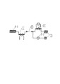
Сущность изобретения поясняется схемой заявляемого устройства.The essence of the invention is illustrated by the scheme of the proposed device.
Позициями на чертеже обозначены:The positions in the drawing indicate:
Однопроводная линия однофазного переменного тока;Single-wire line of single-phase alternating current;
Накопитель электрических зарядов питающего трансформатора;Accumulator of electric charges of the supply transformer;
Питающий трансформатор (источник питания);Supply transformer (power supply);
Приемник электрической энергии;Receiver of electrical energy;
Накопитель электрических зарядов приемника электрической энергии;The accumulator of electric charges of the receiver of electric energy;
Трансформатор приемника электрической энергии.Transformer for the receiver of electrical energy.
Устройство содержит однопроводную линию 1 однофазного переменного тока, к входу которой подключена одним выводом вторичная обмотка питающего трансформатора 3, второй вывод которой соединен с накопителем 2 электрических зарядов питающего трансформатора 3. Выход однопроводной линии 1 подключен, по крайней мере, к одному приемнику 4 напрямую или через трансформатор 6 приемника 4 электрической энергии. Второй вывод каждого приемника 4 или трансформатора 6 приемника в свою очередь подключен к накопителю 5 электрических зарядов приемника 4, как показано на чертеже. Первичная обмотка трансформатора 3 подключена к источнику однофазного переменного тока (на чертеже не показан), выполненному с возможностью изменения частоты.The device contains a single-
Принцип работы устройства будет понятен из принципа работы известной из уровня техники электрической схемы (последовательное соединение в цепи переменного тока приемника и конденсатора), демонстрирующей прохождение переменного тока к приемнику через конденсатор. Принцип «прохождения» тока основан на попеременном заряде / перезаряде обкладок конденсатора за счет изменения направления течения тока в схеме. При этом сила тока зависит от емкости конденсатора и определяется известными из курса физики формулами. В случае рассматриваемого устройства роль обкладок конденсатора играют разнесенные в пространстве накопители 2 и 5. При разделении обкладок конденсатора и разнесение их на расстояние емкость конденсатора уменьшается, что влечет за собой снижение тока в цепи. Описываемое устройство является логическим продолжением известной электрической схемы, в которой обкладки конденсатора разнесены на значительное расстояние, а для поддержки необходимого тока в цепи электрическая ёмкость каждой из них увеличена. Кроме увеличения электрических ёмкостей для увеличения передаваемой мощности повышают частоту переменного тока. The principle of operation of the device will be clear from the principle of operation of the electrical circuit known from the prior art (series connection in the AC circuit of the receiver and capacitor), demonstrating the passage of alternating current to the receiver through the capacitor. The principle of "passage" of current is based on the alternating charge / recharge of the capacitor plates due to a change in the direction of current flow in the circuit. In this case, the current strength depends on the capacitance of the capacitor and is determined by the formulas known from the course of physics. In the case of the device under consideration, the role of the capacitor plates is played by
Таким образом, устройство состоит из последовательно соединённых: накопителя 2 питающего трансформатора; вторичной обмотки питающего трансформатора 3; однопроводной линии 1; приемника 4 (электрической энергии) и накопителя 5 приемника электрической энергии. В другом варианте исполнения устройства приемник 4 может получать питание из однопроводной линии 1 через трансформатор 6.Thus, the device consists of series-connected: drive 2 supply transformer; secondary winding of the
Устройство работает следующим образом: за счет внешней энергии источника однофазного переменного тока (на чертеже не показано) через вторичную обмотку питающего трансформатора 3, обеспечивается знакопеременное движение потока электронов по однопроводной цепи от накопителя 2 электрической энергии к накопителю 5 электрической энергии. При этом ток проходит через приемник 4, где и совершает работу.The device operates as follows: due to the external energy of a single-phase alternating current source (not shown in the drawing) through the secondary winding of the
Устройство использует возможности накопителей электрических зарядов (приемника и питающего трансформатора) обеспечивать скорость накопления и отдачи электрических зарядов (электронов) в однопроводную цепь. При этом сила тока в однопроводной цепи будет зависеть от ряда условий: возможности накопителей 2 и 5 электрических зарядов поддерживать скорость и объем приема / отдачи электрических зарядов и омического сопротивления однопроводной линии. При использовании в устройстве нескольких приемников электрической энергии все они подключаются к однопроводной линии со своими накопителями электрических зарядов. При этом должно соблюдаться условие, что суммарная электрическая ёмкость всех накопителей 5 равна электрической ёмкости накопителя 2.The device uses the capabilities of electric charge accumulators (receiver and supply transformer) to ensure the rate of accumulation and return of electric charges (electrons) to a single-wire circuit. In this case, the current strength in a single-wire circuit will depend on a number of conditions: the ability of
В качестве накопителей 2 или 5 электрической энергии могут использоваться обкладки конденсаторов, массивные токопроводящие конструкции и материалы. При использовании конденсаторов в качестве накопителя электрической энергии в зависимости от конструкции конденсатора можно использовать одну из его обкладок или обе. Токопроводящие конструкции при использовании в качестве накопителей 2 или 5 электрической энергии могут заземляться, что увеличивает их электрическую ёмкость. Одновременное заземление накопителей 2 и 5 электрической энергии, возможно при их удалении друг от друга на расстояние, исключающее перетоки через землю. В качестве трансформаторов используются силовые трансформаторы с гальванической развязкой обмоток. В качестве однопроводной линии 1 возможно использование специальной линии, например, проводной, а также токопроводящих конструкций и природных токопроводящих сред, например, водоемов. В этом случае необходима изоляция накопителей электрических зарядов. Если используют в качестве накопителей электрических зарядов удаленные друг от друга токопроводящие природные среды, то изолируется однопроводная линия.Capacitor plates, massive conductive structures and materials can be used as electric
Для использования устройства в качестве передачи зарядного тока или электроснабжения мобильных устройств - изолируют накопители электрических зарядов, которые располагаются внутри мобильного устройства и зарядного устройства. В качестве однопроводной линии используется однопроводный контакт через контактные поверхности мобильного и зарядного устройств. В этом случае оба контакта являются частью однопроводной линии. При соприкосновении контактов происходит заряд мобильного устройства или его электропитание, например, при установке смартфона в гнездо зарядного устройства или нахождении его в ячейке панели автомобиля с контактной пластиной. Преимуществом использования устройства - мобильное устройство может не иметь специального разъёма для подзарядки и из-за этого его герметичность и удобство пользования им будут выше. Такой вариант применения устройства будет универсальным, экологичным и более эффективным, чем беспроводные зарядки известные из уровня техники, в том числе и известная технология питания Qi.To use the device as a transmission of charging current or power supply to mobile devices, the electric charge accumulators are isolated, which are located inside the mobile device and the charger. As a single-wire line, a single-wire contact is used through the contact surfaces of the mobile and charger. In this case, both contacts are part of a single-wire line. When the contacts come into contact, the mobile device is charged or powered, for example, when a smartphone is placed in the charger socket or when it is in a car panel cell with a contact plate. The advantage of using the device is that a mobile device may not have a special connector for recharging, and because of this, its tightness and ease of use will be higher. Such an application of the device will be versatile, environmentally friendly and more efficient than wireless charging known from the prior art, including the well-known Qi power technology.
Устройство позволяет производить электропитание мобильного устройства с низким электропотреблением без внутреннего аккумулятора при однопроводном подключении к токопроводящей конструкции. В этом случае отпадает необходимость обеспечивать условия работы для аккумуляторных батарей, например, минимальный уровень заряда или температурный диапазон. Примером такого устройства может быть переносной светильник содержащий источник света и электрическую емкость для работы, например, в условиях низких температур. Для этого мобильное устройство подключают к однопроводной линии в любом доступном месте этой линии, в качестве которой может быть рельсовый путь, металлическая конструкция, оборудование и т.д.The device allows power supply of a mobile device with low power consumption without an internal battery when connected to a conductive structure with a single wire. In this case, there is no need to provide operating conditions for batteries, such as a minimum charge level or temperature range. An example of such a device can be a portable lamp containing a light source and an electrical capacitance for operation, for example, at low temperatures. To do this, the mobile device is connected to a single-wire line in any accessible place of this line, which can be a rail track, a metal structure, equipment, etc.
При возможности использовать полноценное электрическое снабжение (одно- или трехфазное) рассматриваемое устройство будет малопригодным, кроме варианта зарядки для мобильных устройств (гаджетов). Поэтому использование устройства эффективно для удаленных от линий электропередач приемников электрической энергии с относительно низким уровнем энергопотребления, например, контрольно-измерительных и автоматизированных устройств (КИПиА), находящихся под водой, по трассе магистральных трубопроводов или рельсовых путей. При этом для повышения эффективности передачи электрической энергии (прием / отдача электрических зарядов накопителями) подбирают частоту переменного тока подаваемого на питающий трансформатор исходя из параметров всех элементов схемы однопроводного электроснабжения. Изменение частоты в каждом конкретном случае препятствует несанкционированному отбору электрической энергии от однопроводной линии.If it is possible to use a full-fledged electrical supply (single- or three-phase), the device in question will be of little use, except for the charging option for mobile devices (gadgets). Therefore, the use of the device is effective for electrical energy receivers remote from power lines with a relatively low level of energy consumption, for example, instrumentation and automated devices (I&C) located under water, along the route of main pipelines or rail tracks. At the same time, in order to increase the efficiency of the transmission of electrical energy (reception / return of electric charges by storage devices), the frequency of the alternating current supplied to the supply transformer is selected based on the parameters of all elements of the single-wire power supply circuit. Changing the frequency in each specific case prevents unauthorized selection of electrical energy from a single-wire line.
Таким образом, достигается технический результат - создание простого и безопасного устройства для альтернативного электроснабжения стационарных или зарядки и электроснабжения мобильных приемников электрической энергии по однопроводной линии переменного тока.Thus, the technical result is achieved - the creation of a simple and safe device for alternative power supply to stationary or charging and power supply of mobile electrical energy receivers via a single-wire AC line.
Примеры конкретного выполнения.Examples of specific implementation.
Пример 1. Электропитание стационарного удаленного устройства, например, измерительного датчика с низким энергопотреблением на магистральном трубопроводе. Для электропитания необходима либо линия электропередач (ЛЭП), либо альтернативные источники энергии, например, энергия Солнца. В случае удаленности: ЛЭП - дорого, а устройства получения энергии от солнечных лучей сложны и не имеют антивандальной защиты. Электропитание датчика от заявленного устройства в этом случае самый оптимальный вариант. При этом питающий трансформатор 3 с накопителем 2 электрических зарядов находится на участке трубопровода с надежным электроснабжением, например, на компрессорной станции, и присоединён к магистральному трубопроводу, а трансформатор 6 приемника с накопителем 5 внутри или рядом с измерительным датчиком в антивандальном исполнении. Магистральный трубопровод - однопроводная линия 1.Example 1: Powering a fixed remote device, such as a low power measuring sensor on a main pipeline. Power supply requires either a power line (power line) or alternative energy sources, such as solar energy. In the case of remoteness: Power lines are expensive, and devices for obtaining energy from solar rays are complex and do not have anti-vandal protection. Power supply of the sensor from the declared device in this case is the best option. At the same time, the
Пример 2. Электрическая зарядка аккумулятора мобильного устройства, например, смартфона. Смартфон вставляется в «подставку-зарядку» или помещается в гнездо (ячейка) на панели автомобиля. При этом и в том и в другом случае, обеспечивается контакт двух токопроводящих поверхностей, одна, из которых на смартфоне, другая на зарядке - подставке или части гнезда на панели автомобиля. При этом питающий трансформатор 3 с накопителем 2 электрических зарядов находятся внутри подставки / гнезда (автомобиля), а трансформатор 6 приемника с накопителем 5 внутри смартфона. Контакт между смартфоном и подставкой (автомобилем) - однопроводная линия 1.Example 2. Electric charging of the battery of a mobile device, such as a smartphone. The smartphone is inserted into the "stand-charging" or placed in the socket (cell) on the car panel. In this case, in both cases, the contact of two conductive surfaces is ensured, one of which is on the smartphone, the other on the charging stand or part of the socket on the car panel. In this case, the
Пример 3. Электрическое питание мобильного устройства. Например, малогабаритный светильник для локального освещения рабочей зоны при ремонте оборудования. Ремонтируемое (токопроводящее) оборудование используется в качестве однопроводной линии, которая одним концом соединена с питающим трансформатором, а другим с мобильными светильником, которые с помощью контактного зажима может быть прикреплен и получать электропитание в любом месте этого оборудования. При ремонте, например, автомобиля такие устройства могут быть эффективной заменой используемых «переносок» (проводной светильник) либо налобных фонарей. При этом питающий трансформатор 3 с накопителем 2 электрических зарядов находятся внутри внешнего и подключаемого к сети переменного тока устройства, которое подключается к токопроводящему оборудованию на период ремонта, а трансформатор 6 приемника с накопителем 5 внутри малогабаритного светильника. Токопроводящее оборудование - однопроводная линия 1.Example 3. Power supply of a mobile device. For example, a small-sized luminaire for local illumination of the working area during equipment repair. Repaired (conductive) equipment is used as a single-wire line, which is connected at one end to a supply transformer, and at the other end to mobile lamps, which can be attached using a contact clamp and receive power anywhere in this equipment. When repairing, for example, a car, such devices can be an effective replacement for the used “carriers” (wire lamp) or headlamps. At the same time, the
Claims (6)
Publications (1)
| Publication Number | Publication Date |
|---|---|
| RU2771663C1 true RU2771663C1 (en) | 2022-05-11 |
Family
ID=
Citations (7)
| Publication number | Priority date | Publication date | Assignee | Title |
|---|---|---|---|---|
| US593138A (en) * | 1897-11-02 | Nikola Tesla | Electrical Transformer | |
| RU2245598C1 (en) * | 2003-07-11 | 2005-01-27 | Стребков Дмитрий Семенович | Method and device for electrical energy transmission |
| UA85168C2 (en) * | 2005-03-15 | 2009-01-12 | Николай Борисович Костюченко | Method for electromagnetic energy transfer (embodiments) |
| RU106458U1 (en) * | 2011-01-11 | 2011-07-10 | ООО "Научно-производственное объединение "Современные диагностические системы" (ООО "НПО "СОДИС") | POWER-SAVING SINGLE-WIRED RESONANCE ELECTRIC POWER TRANSMISSION SYSTEM |
| RU2423772C1 (en) * | 2010-03-23 | 2011-07-10 | Российская академия сельскохозяйственных наук Государственное научное учреждение Всероссийский научно-исследовательский институт электрификации сельского хозяйства Российской академии сельскохозяйственных наук (ГНУ ВИЭСХ Россельхозакадемии) | Method and device of electric energy transfer (versions) |
| CN205263566U (en) * | 2015-11-27 | 2016-05-25 | 浙江正泰建筑电器有限公司 | Single live wire power supply line control system |
| RU2626815C2 (en) * | 2015-10-14 | 2017-08-02 | Федеральное государственное бюджетное научное учреждение "Федеральный научный агроинженерный центр ВИМ" (ФГБНУ ФНАЦ ВИМ) | Method and device for transmission of electric power |
Patent Citations (7)
| Publication number | Priority date | Publication date | Assignee | Title |
|---|---|---|---|---|
| US593138A (en) * | 1897-11-02 | Nikola Tesla | Electrical Transformer | |
| RU2245598C1 (en) * | 2003-07-11 | 2005-01-27 | Стребков Дмитрий Семенович | Method and device for electrical energy transmission |
| UA85168C2 (en) * | 2005-03-15 | 2009-01-12 | Николай Борисович Костюченко | Method for electromagnetic energy transfer (embodiments) |
| RU2423772C1 (en) * | 2010-03-23 | 2011-07-10 | Российская академия сельскохозяйственных наук Государственное научное учреждение Всероссийский научно-исследовательский институт электрификации сельского хозяйства Российской академии сельскохозяйственных наук (ГНУ ВИЭСХ Россельхозакадемии) | Method and device of electric energy transfer (versions) |
| RU106458U1 (en) * | 2011-01-11 | 2011-07-10 | ООО "Научно-производственное объединение "Современные диагностические системы" (ООО "НПО "СОДИС") | POWER-SAVING SINGLE-WIRED RESONANCE ELECTRIC POWER TRANSMISSION SYSTEM |
| RU2626815C2 (en) * | 2015-10-14 | 2017-08-02 | Федеральное государственное бюджетное научное учреждение "Федеральный научный агроинженерный центр ВИМ" (ФГБНУ ФНАЦ ВИМ) | Method and device for transmission of electric power |
| CN205263566U (en) * | 2015-11-27 | 2016-05-25 | 浙江正泰建筑电器有限公司 | Single live wire power supply line control system |
Similar Documents
| Publication | Publication Date | Title |
|---|---|---|
| US8604746B2 (en) | Contactless power charging system and energy storage system including the same | |
| US11241975B2 (en) | Electric vehicle home microgrid power system | |
| US9153976B2 (en) | System and method of battery temperature control | |
| Khutwad et al. | Wireless charging system for electric vehicle | |
| RU2011142749A (en) | VOLTAGE STABILIZER FOR POWER SYSTEM | |
| WO2017084599A1 (en) | A wireless power transfer system | |
| CN103595084A (en) | Mobile power source having wireless charging and discharging functions | |
| CN112136258A (en) | Electric energy distribution system | |
| KR101533558B1 (en) | Portable charging apparatus for industrial | |
| RU2771663C1 (en) | Device for the transmission of electric energy | |
| Asad et al. | A quantitative analysis of effects of transition from ac to dc system, on storage and distribution systems | |
| Shakya et al. | Implementation of Inductive Wireless Power Transmission system for Battery Charging applications | |
| US20220166219A1 (en) | Systems and methods for modular power conversion units in power supply systems | |
| Mauromicale et al. | E-mobility: Safety, service continuity and penetration of charging systems | |
| WO2012043589A1 (en) | Power supply device | |
| KR101273976B1 (en) | Condenser charge/discharge apparatus using by solar cell and generator | |
| CN103248104A (en) | Wireless rechargeable battery | |
| Lai et al. | A Novel Wireless Power Transfer System with Reflex-Charging and Cell-Balancing Functions | |
| RU209253U1 (en) | Uninterruptible power supply with the possibility of energy recovery | |
| KR102303342B1 (en) | A method for controlling relay to prevent relay damage due to rush current | |
| Lamghari et al. | Design of a wireless battery charging system for electric vehicles | |
| KR20220082878A (en) | Devices for the generation, storage and distribution of electrical energy | |
| KR101233785B1 (en) | Adc power supply system | |
| RU120818U1 (en) | HIGH VOLTAGE DC ELECTRICITY TRANSMISSION SYSTEM | |
| US20160226304A1 (en) | Electrical power generation system |