RU2765869C2 - Double-sided cutting insert with orientation-facilitating clamping recesses, and cutting tool - Google Patents
Double-sided cutting insert with orientation-facilitating clamping recesses, and cutting tool Download PDFInfo
- Publication number
- RU2765869C2 RU2765869C2 RU2020114322A RU2020114322A RU2765869C2 RU 2765869 C2 RU2765869 C2 RU 2765869C2 RU 2020114322 A RU2020114322 A RU 2020114322A RU 2020114322 A RU2020114322 A RU 2020114322A RU 2765869 C2 RU2765869 C2 RU 2765869C2
- Authority
- RU
- Russia
- Prior art keywords
- insert
- recess
- cutting
- clamping
- median plane
- Prior art date
Links
- 238000005520 cutting process Methods 0.000 title claims abstract description 76
- 230000002093 peripheral effect Effects 0.000 claims abstract description 37
- 230000000694 effects Effects 0.000 abstract description 2
- 239000000126 substance Substances 0.000 abstract 1
- 238000007514 turning Methods 0.000 description 4
- 238000009434 installation Methods 0.000 description 3
- 238000006073 displacement reaction Methods 0.000 description 2
- 238000003754 machining Methods 0.000 description 2
- 230000000007 visual effect Effects 0.000 description 2
- 230000001154 acute effect Effects 0.000 description 1
- 239000011230 binding agent Substances 0.000 description 1
- 230000008878 coupling Effects 0.000 description 1
- 238000010168 coupling process Methods 0.000 description 1
- 238000005859 coupling reaction Methods 0.000 description 1
- 238000005516 engineering process Methods 0.000 description 1
- 238000003780 insertion Methods 0.000 description 1
- 230000037431 insertion Effects 0.000 description 1
- 238000004519 manufacturing process Methods 0.000 description 1
- 239000000463 material Substances 0.000 description 1
- 239000000843 powder Substances 0.000 description 1
- 238000003825 pressing Methods 0.000 description 1
- 238000005245 sintering Methods 0.000 description 1
- UONOETXJSWQNOL-UHFFFAOYSA-N tungsten carbide Chemical compound [W+]#[C-] UONOETXJSWQNOL-UHFFFAOYSA-N 0.000 description 1
Images
Classifications
-
- B—PERFORMING OPERATIONS; TRANSPORTING
- B23—MACHINE TOOLS; METAL-WORKING NOT OTHERWISE PROVIDED FOR
- B23B—TURNING; BORING
- B23B27/00—Tools for turning or boring machines; Tools of a similar kind in general; Accessories therefor
- B23B27/14—Cutting tools of which the bits or tips or cutting inserts are of special material
- B23B27/16—Cutting tools of which the bits or tips or cutting inserts are of special material with exchangeable cutting bits or cutting inserts, e.g. able to be clamped
- B23B27/1603—Cutting tools of which the bits or tips or cutting inserts are of special material with exchangeable cutting bits or cutting inserts, e.g. able to be clamped with specially shaped plate-like exchangeable cutting inserts, e.g. chip-breaking groove
- B23B27/1611—Cutting tools of which the bits or tips or cutting inserts are of special material with exchangeable cutting bits or cutting inserts, e.g. able to be clamped with specially shaped plate-like exchangeable cutting inserts, e.g. chip-breaking groove characterised by having a special shape
-
- B—PERFORMING OPERATIONS; TRANSPORTING
- B23—MACHINE TOOLS; METAL-WORKING NOT OTHERWISE PROVIDED FOR
- B23B—TURNING; BORING
- B23B27/00—Tools for turning or boring machines; Tools of a similar kind in general; Accessories therefor
- B23B27/14—Cutting tools of which the bits or tips or cutting inserts are of special material
- B23B27/16—Cutting tools of which the bits or tips or cutting inserts are of special material with exchangeable cutting bits or cutting inserts, e.g. able to be clamped
- B23B27/1614—Cutting tools of which the bits or tips or cutting inserts are of special material with exchangeable cutting bits or cutting inserts, e.g. able to be clamped with plate-like cutting inserts of special shape clamped against the walls of the recess in the shank by a clamping member acting upon the wall of a hole in the insert
- B23B27/1622—Cutting tools of which the bits or tips or cutting inserts are of special material with exchangeable cutting bits or cutting inserts, e.g. able to be clamped with plate-like cutting inserts of special shape clamped against the walls of the recess in the shank by a clamping member acting upon the wall of a hole in the insert characterised by having a special shape
-
- B—PERFORMING OPERATIONS; TRANSPORTING
- B23—MACHINE TOOLS; METAL-WORKING NOT OTHERWISE PROVIDED FOR
- B23C—MILLING
- B23C5/00—Milling-cutters
- B23C5/16—Milling-cutters characterised by physical features other than shape
- B23C5/20—Milling-cutters characterised by physical features other than shape with removable cutter bits or teeth or cutting inserts
- B23C5/22—Securing arrangements for bits or teeth or cutting inserts
-
- B—PERFORMING OPERATIONS; TRANSPORTING
- B23—MACHINE TOOLS; METAL-WORKING NOT OTHERWISE PROVIDED FOR
- B23B—TURNING; BORING
- B23B2200/00—Details of cutting inserts
- B23B2200/36—Other features of cutting inserts not covered by B23B2200/04 - B23B2200/32
- B23B2200/3618—Fixation holes
-
- B—PERFORMING OPERATIONS; TRANSPORTING
- B23—MACHINE TOOLS; METAL-WORKING NOT OTHERWISE PROVIDED FOR
- B23B—TURNING; BORING
- B23B2200/00—Details of cutting inserts
- B23B2200/36—Other features of cutting inserts not covered by B23B2200/04 - B23B2200/32
- B23B2200/3681—Split inserts, i.e. comprising two or more sections roughly equal in size and having similar or dissimilar cutting geometries
Abstract
Description
ОБЛАСТЬ ТЕХНИКИFIELD OF TECHNOLOGY
[001] Объект настоящей заявки относится к инструментам для механической обработки или стружкоснимающим режущим инструментам. В частности, он относится к двухсторонним режущим вставкам, которые включают в себя выполняемую с защитой от случайных ошибок коррекцию установки или способствующие ориентации соединительные выемки, которые предотвращают неправильную посадку вставки в гнездо и последующее повреждение гнезда.[001] The subject matter of this application relates to machining tools or chip-removing cutting tools. In particular, it relates to double-sided cutting inserts which include error-proof installation correction or orientation-promoting connecting recesses which prevent the insert from misfitting into the socket and subsequent damage to the socket.
УРОВЕНЬ ТЕХНИКИBACKGROUND OF THE INVENTION
[002] В данной области техники известно, что неправильная ориентация вставки в гнезде может привести к повреждению вставки, заготовки, гнезда и даже всего инструмента.[002] It is known in the art that incorrect orientation of the insert in the socket can damage the insert, the workpiece, the socket, and even the entire tool.
[003] В некоторых вставках из-за определенных симметричностей и/или небольшого размера может быть затруднительным увидеть невооруженным глазом различия между областью вставки, предназначенной для резания, и областью, предназначенной только для упирания. Таким образом, во множестве случаев применения является проблематичным для оператора определить и закрепить вставку в правильной ориентации в гнезде. Для предотвращения неправильной установки или крепления вставки в гнезде некоторые изготовители включают визуальные ориентиры, такие как маркировки (нумерация, символы). Визуальные ориентиры обычно работают хорошо, однако в множестве случаев применения они являются неэффективными. Например, при плохом освещении обычно оператор может неправильно прочитать маркировку на современных миниатюрных вставках.[003] In some inserts, due to certain symmetries and/or small size, it can be difficult to see with the naked eye the difference between the area of the insert intended for cutting and the area intended only for abutment. Thus, in many applications it is problematic for the operator to determine and secure the insert in the correct orientation in the socket. To prevent incorrect installation or fastening of the insert in the socket, some manufacturers include visual cues such as markings (numbering, symbols). Visual cues usually work well, but in many applications they are ineffective. For example, under poor lighting, the operator can usually misread the markings on modern miniature inserts.
[004] Вставками другого типа, которые могут вызвать подобные проблемы, являются вставки, которые имеют более чем один различающийся режущий участок на одиночной основной поверхности.[004] Another type of insert that can cause similar problems are inserts that have more than one distinct cutting portion on a single major surface.
[005] Настоящее изобретение преодолевает вышеуказанные недостатки путем обеспечения конфигурации, которая способствует ориентации и которая может быть независимой от режущего участка (участков) и/или конфигурации наружного упирания.[005] The present invention overcomes the above disadvantages by providing a configuration that facilitates orientation and that can be independent of the cutting section(s) and/or the external abutment configuration.
РАСКРЫТИЕ СУЩНОСТИ ИЗОБРЕТЕНИЯDISCLOSURE OF THE INVENTION
[006] Согласно первому аспекту объекта настоящего изобретения обеспечена двухсторонняя режущая вставка, имеющая способствующую ориентации конфигурацию, содержащая:[006] According to a first aspect of an aspect of the present invention, there is provided a double-sided cutting insert having an orientation-enhancing configuration, comprising:
противоположные и идентичные первую и вторую основные поверхности и периферийную поверхность, проходящую между ними; иopposite and identical first and second major surfaces and a peripheral surface extending therebetween; and
противоположные первую и вторую зажимные выемки, открытые соответственно к первой и второй основным поверхностям;opposite first and second clamping recesses, respectively open to the first and second major surfaces;
причемand
при наложении на срединную плоскость первая и вторая зажимные выемки полностью не перекрываются.when applied to the median plane, the first and second clamping recesses do not completely overlap.
[007] Согласно второму аспекту объекта настоящего изобретения обеспечена двухсторонняя режущая вставка, имеющая способствующую ориентации конфигурацию и центральную ось, вокруг которой вставка выполнена с возможностью индексирования, и содержащая:[007] According to a second aspect of the subject matter of the present invention, there is provided a double-sided cutting insert having an orientation-enhancing configuration and a central axis about which the insert is indexable, and comprising:
противоположные и идентичные первую и вторую основные поверхности и периферийную поверхность вставки, проходящую между ними, причем каждая основная поверхность содержит режущий участок;opposite and identical first and second major surfaces and an insert peripheral surface extending therebetween, each major surface comprising a cutting portion;
срединную плоскость, перпендикулярную центральной оси и расположенную посередине между первой и второй основными поверхностями; иa median plane perpendicular to the central axis and located midway between the first and second major surfaces; and
противоположные первую и вторую зажимные выемки, открытые соответственно к первой и второй основным поверхностям;opposite first and second clamping recesses, respectively open to the first and second major surfaces;
причем:and:
каждая зажимная выемка является удлиненной в направлении, параллельном срединной плоскости, вдоль продольной оси;each clamp recess is elongated in a direction parallel to the median plane, along the longitudinal axis;
каждая зажимная выемка содержит периферийную поверхность выемки, которая содержит по меньшей мере одну упорную поверхность выемки; иeach clamp recess includes a peripheral recess surface that includes at least one recess abutment surface; and
проекции на срединную плоскость по меньшей мере участков первой и второй зажимных выемок смещены относительно друг друга в направлении вращения вокруг центральной оси.projections onto the median plane of at least portions of the first and second clamping recesses are displaced relative to each other in the direction of rotation around the central axis.
[008] Согласно третьему аспекту объекта настоящего изобретения обеспечен режущий инструмент, содержащий корпус инструмента, имеющий гнездо, и вставку, закрепленную в нем, причем гнездо содержит:[008] According to a third aspect of the subject matter of the present invention, a cutting tool is provided, comprising a tool body having a socket and an insert fixed therein, the socket comprising:
базовую упорную поверхность;base thrust surface;
первую и вторую стеночные упорные поверхности иfirst and second wall thrust surfaces and
зажимной элемент, выполненный с возможностью упирания в одну из первой и второй зажимных выемок вставки и ее фиксации для закрепления таким образом вставки в гнезде.a clamping element configured to abut against one of the first and second clamping recesses of the insert and fix it to thereby secure the insert in the socket.
[009] Любой из следующих признаков либо один, либо в сочетании может быть применимым к любому из вышеуказанных аспектов объекта настоящего изобретения:[009] Any of the following features, either alone or in combination, may be applicable to any of the above aspects of the subject matter of the present invention:
[0010] Ни один режущий участок первой основной поверхности не расположен противоположно режущему участку второй основной поверхности.[0010] None of the cutting portion of the first major surface is located opposite the cutting portion of the second major surface.
[0011] Режущая вставка содержит ровно два режущих участка.[0011] The cutting insert contains exactly two cutting sections.
[0012] Первая и вторая зажимные выемки соединены друг с другом так, что образуют сквозное отверстие, соединяющее первую и вторую основные поверхности.[0012] The first and second clamping recesses are connected to each other so as to form a through hole connecting the first and second major surfaces.
[0013] В проекции на срединную плоскость очертаний двух периферийных поверхностей выемки проецируемое очертание одной периферийной поверхности выемки пересекает проецируемое очертание другой периферийной поверхности выемки только в четырех общих точках.[0013] In a midplane projection of the outlines of the two peripheral recess surfaces, the projected outline of one peripheral recess surface intersects the projected outline of the other peripheral recess surface at only four common points.
[0014] В проекции на срединную плоскость очертаний двух периферийных поверхностей выемки проецируемое очертание одной периферийной поверхности выемки смещено в направлении вращения вокруг центральной оси относительно проецируемого очертания другой периферийной поверхности выемки.[0014] In the projection on the median plane of the outlines of the two peripheral surfaces of the recess, the projected outline of one peripheral surface of the recess is shifted in the direction of rotation around the central axis relative to the projected outline of the other peripheral surface of the recess.
[0015] В проекции на срединную плоскость очертаний двух периферийных поверхностей выемки ни один участок проецируемого очертания одной периферийной поверхности выемки не является касательным ни к какому участку проецируемого очертания другой периферийной поверхности выемки.[0015] In the midplane projection of the outlines of the two peripheral surfaces of the recess, no portion of the projected outline of one peripheral surface of the recess is tangent to any portion of the projected outline of the other peripheral surface of the recess.
[0016] Продольные оси образуют между собой угол смещения; причем угол (α) смещения составляет 90°.[0016] The longitudinal axes form an offset angle between them; wherein the displacement angle (α) is 90°.
[0017] Упорная поверхность выемки может проходить в направлении, перпендикулярном срединной плоскости.[0017] The abutment surface of the recess may extend in a direction perpendicular to the median plane.
[0018] Зажимные выемки являются нерезьбовыми.[0018] The clamping recesses are non-threaded.
[0019] Каждая зажимная выемка длиннее в направлении вдоль своей соответствующей продольной оси, чем в любом другом направлении.[0019] Each clamp recess is longer in the direction along its respective longitudinal axis than in any other direction.
[0020] Ни одна из зажимных выемок не проходит за пределы срединной плоскости.[0020] None of the clamping recesses extend beyond the median plane.
[0021] Первая и вторая зажимные выемки идентичны друг другу.[0021] The first and second clamping recesses are identical to each other.
[0022] Каждая зажимная выемка также содержит винтовую упорную поверхность, которая открыта к соответствующей основной упорной поверхности.[0022] Each clamping recess also includes a helical stop surface that is open to a respective main stop surface.
[0023] Одна из первой и второй основных поверхностей упирается в базовую упорную поверхность, и периферийная поверхность вставки упирается в первую и вторую стеночные упорные поверхности.[0023] One of the first and second main surfaces abuts against the base abutment surface, and the peripheral surface of the insert abuts against the first and second wall abutment surfaces.
[0024] Корпус инструмента также содержит регулировочное отверстие, выполненное с возможностью размещения в нем регулировочного винта;[0024] The tool body also includes an adjustment hole configured to accommodate an adjustment screw;
зажимной элемент является зажимным рычагом, занимающим зажимное отверстие, которое соединено с регулировочным отверстием; иthe clamping member is a clamping arm occupying a clamping hole which is connected to the adjusting hole; and
зажимной рычаг упирается в упорную поверхность выемки для закрепления вставки в гнезде.the clamping lever abuts against the stop surface of the recess to secure the insert in the socket.
[0025] Каждая из зажимных выемок также содержит винтовую упорную поверхность, которая открыта к соответствующей основной упорной поверхности; и[0025] Each of the clamping recesses also includes a helical stop surface that is open to a respective main stop surface; and
зажимной элемент является зажимающим винтом, который упирается в винтовую упорную поверхность для закрепления вставки в гнезде без контакта с упорной поверхностью выемки.the clamping element is a clamping screw that abuts against the helical abutment surface to secure the insert in the socket without contact with the abutment surface of the recess.
КРАТКОЕ ОПИСАНИЕ ЧЕРТЕЖЕЙBRIEF DESCRIPTION OF THE DRAWINGS
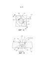
[0026] Для лучшего понимания объекта настоящего изобретения и показа, каким образом оно может быть выполнено практически, ниже приведены сопроводительные чертежи, на которых:[0026] For a better understanding of the object of the present invention and showing how it can be carried out in practice, the following are the accompanying drawings, in which:
На ФИГ. 1 изображен полупокомпонентный вид в перспективе токарного резца с вставкой для токарной обработки;FIG. 1 is an exploded perspective view of a turning tool with a turning insert;
На ФИГ. 2 изображен вид сбоку инструмента по ФИГ. 1 с вставкой, закрепленной в гнезде;FIG. 2 is a side view of the tool of FIG. 1 with an insert fixed in the socket;
На ФИГ. 3 изображен вид сверху инструмента по ФИГ. 1;FIG. 3 is a plan view of the tool of FIG. one;
На ФИГ. 4 изображен разрез инструмента, изображенного на ФИГ. 1, полученный по линии IV-IV, изображенной на ФИГ. 3;FIG. 4 is a sectional view of the tool shown in FIG. 1 obtained along the line IV-IV shown in FIG. 3;
На ФИГ. 5 изображен разрез инструмента, изображенного на ФИГ. 1, полученный по линии V-V, изображенной на ФИГ. 3;FIG. 5 is a sectional view of the instrument shown in FIG. 1 taken along the V-V line shown in FIG. 3;
На ФИГ. 6 изображен изометрический вид вставки по ФИГ. 1;FIG. 6 is an isometric view of the insert of FIG. one;
На ФИГ. 7 изображен вид сверху первой основной поверхности вставки, изображенной на ФИГ. 1, с невидимыми линиями, которые представляют по меньшей мере часть признаков противоположной второй основной поверхности;FIG. 7 is a plan view of the first major surface of the insert shown in FIG. 1 with invisible lines that represent at least part of the features of the opposite second major surface;
На ФИГ. 8 изображен вид сбоку вставки по ФИГ. 1;FIG. 8 is a side view of the insert of FIG. one;
На ФИГ. 9 изображен вид сверху первой основной поверхности вставки по ФИГ. 1; иFIG. 9 is a plan view of the first major surface of the insert of FIG. one; and
На ФИГ. 10 изображен разрез вставки, изображенной на ФИГ. 1, полученный по линии X-X, изображенной на ФИГ. 9.FIG. 10 is a sectional view of the insert shown in FIG. 1 taken along the line X-X shown in FIG. 9.
На ФИГ. 11 изображен вид сверху второго варианта реализации собранного токарного резца;FIG. 11 is a plan view of a second embodiment of an assembled turning tool;
На ФИГ. 12 изображен разрез, полученный по линии XII-XII, изображенной на ФИГ. 11;FIG. 12 shows a section taken along the line XII-XII shown in FIG. eleven;
На ФИГ. 13 изображен разрез, полученный по линии XIII-XIII, изображенной на ФИГ. 12;FIG. 13 is a sectional view taken along line XIII-XIII of FIG. 12;
На ФИГ. 14 изображен вид сверху первой основной поверхности вставки по ФИГ. 11 с невидимыми линиями, которые представляют по меньшей мере часть признаков противоположной второй основной поверхности;FIG. 14 is a plan view of the first major surface of the insert of FIG. 11 with invisible lines that represent at least part of the features of the opposite second major surface;
На ФИГ. 15 изображен разрез, полученный по линии XV-XV, изображенной на ФИГ. 14.FIG. 15 is a sectional view taken along line XV-XV of FIG. 14.
[0027] В случае необходимости позиционные номера могут повторяться на чертежах для указания соответствующих или аналогичных элементов.[0027] Where necessary, reference numbers may be repeated throughout the drawings to indicate corresponding or similar elements.
ОСУЩЕСТВЛЕНИЕ ИЗОБРЕТЕНИЯIMPLEMENTATION OF THE INVENTION
[0028] Ниже описаны различные аспекты объекта настоящей заявки. В целях ясности объяснения конкретные конфигурации и детали сформулированы достаточно подробно для полного понимания объекта настоящей заявки. Однако для специалиста также очевидно, что объект настоящей заявки может быть осуществлен без знания конкретных конфигураций и деталей, представленных в настоящем документе.[0028] Various aspects of the subject matter of the present application are described below. For purposes of clarity of explanation, specific configurations and details are set forth in sufficient detail to fully understand the subject matter of the present application. However, it is also obvious to those skilled in the art that the subject matter of the present application may be practiced without knowledge of the specific configurations and details provided herein.
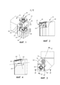
[0029] Как изображено на ФИГ. 1-4, механообрабатывающий или режущий инструмент 10 содержит по меньшей мере одну режущую вставку 12, закрепленную в гнезде 14 корпуса 16 инструмента. Согласно настоящему варианту реализации режущий инструмент 10 является токарным резцом.[0029] As shown in FIG. 1-4, the machining or cutting
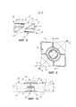
[0030] Вставка 12 является двухсторонней и может быть выполнена с возможностью индексирования. Термин "индексирование" относится к вставкам, которые имеют две или более независимых режущих конфигураций на каждой из двух сторон вставки. Вставка 12 содержит противоположные и идентичные первую и вторую основные поверхности 18, 20 и периферийную поверхность 22 вставки, которая проходит между ними. Первая и вторая основные поверхности для простоты и удобства могут быть названы как верхняя поверхность 18 и нижняя поверхность 20. Каждая из первой и второй основных поверхностей 18, 20 содержит основную упорную поверхность 24. Основные упорные поверхности 24 являются плоскими и параллельными друг другу. Вставка 12 также содержит срединную плоскость P, расположенную точно посередине между первой и второй основными поверхностями 18, 20 и, таким образом, также между основными упорными поверхностями 24. Срединная плоскость P параллельна основным упорным поверхностям 24. Эталонная плоскость R определяется как компланарное расширение каждой из основных упорных поверхностей 24. Вид сверху одной из основных поверхностей 18, 20 направлен перпендикулярно эталонной плоскости R. Срединная плоскость P параллельна эталонной плоскости R. Как показано на ФИГ. 10, высота H вставки определена расстоянием между указанными двумя эталонными плоскостями R.[0030]
[0031] Вставка 12 обычно выполнена из чрезвычайно твердого и износостойкого материала, такого как цементированный карбид, полученный прессованием в форме и спеканием порошков карбида в связующем веществе. Цементированный карбид может быть, например, карбидом вольфрама. Вставка 12 может иметь или не иметь покрытие.[0031]
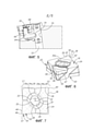
[0032] Как показано на виде, перпендикулярном срединной плоскости P, вставка 12 имеет первую и вторую зажимные выемки 26, 28. Первая и вторая зажимные выемки 26, 28 могут соединяться друг с другом, таким способом образуя сквозное отверстие 27, проходящее через вставку и соединяющее две основных поверхности 18, 20. Каждая из первой и второй зажимных выемок 26, 28 имеет общую центральную ось C вставки, перпендикулярную срединной плоскости P, и проходит вдоль указанной общей центральной оси. Каждая зажимная выемка 26, 28 имеет соответствующую периферийную поверхность 30a, 30b выемки соответственно. Как показано на ФИГ. 7 и 14, на виде вдоль центральной оси C по меньшей мере участок каждой из первой и второй зажимных выемок 26, 28 и, в частности, их соответствующие периферийные поверхности 30a, 30b могут быть удлиненными. Как изображено на тех же чертежах, сплошная линия представляет первую зажимную выемку 26, и штриховая линия представляет вторую зажимную выемку 28, расположенную на противоположной стороне вставки 12. Однако следует понимать, что на ФИГ. 7 и 14 первые зажимные выемки 26, 126 могут быть видимы только до их самых внутренних в радиальном направлении участков. [0032] As shown in the view perpendicular to the median plane P, the
[0033] Также, как изображено на этих чертежах, каждая из указанных двух зажимных выемок 26, 28 может иметь в целом удлиненную или овальную форму. На виде сверху любой из первой или второй основных поверхностей 18, 20 первая и вторая зажимные выемки 26, 28 полностью не перекрываются и в направлении вращения смещены или скручены относительно друг друга вокруг центральной оси C. Иными словами, очертания или контуры удлиненных участков первой и второй зажимных выемок 26, 28, спроецированные или наложенные на срединную плоскость P, полностью не перекрываются и смещены в направлении вращения. Кроме того, очертания первой и второй зажимных выемок 26, 28, проецируемые на срединную плоскость P, не имеют криволинейных участков, которые наложены друг на друга. Иными словами, никакой криволинейный участок очертания одной зажимной выемки не является касательным к криволинейному участку очертания другой зажимной выемки при их проецировании на срединную плоскость P.[0033] Also, as shown in these drawings, each of these two clamping
[0034] Каждая зажимная выемка 26, 28 открыта к соответствующей основной поверхности 18, 20 соответственно. Каждая зажимная выемка 26, 28 может открываться к соответствующей основной упорной поверхности 24, и указанные зажимные выемки могут соединяться друг с другом, образуя таким способом сквозное отверстие 27, проходящее через толщину вставки (как изображено на ФИГ. 10 и 15). Каждая зажимная выемка 26, 28 имеет продольную ось E1, E2 соответственно. Продольные оси E1, E2 представляют направление самого длинного размера соответствующей зажимной выемки (26, 28) на виде сверху одной из первой и второй основных поверхностей 18, 20, взятом перпендикулярно центральной оси C (как изображено на ФИГ. 7 и 14). Каждая продольная ось E1, E2 параллельна срединной плоскости P. Согласно настоящим вариантам реализации каждая зажимная выемка 26, 28 может иметь зеркальную симметрию относительно своей продольной оси E1, E2 на виде вдоль центральной оси C. Центральная ось C перпендикулярна продольным осям E1, E2 и пересекается с ними. Каждая зажимная выемка 26, 28 имеет соответствующую периферийную поверхность 30a, 30b выемки. По меньшей мере участок каждой периферийной поверхности 30a, 30b выемки может быть параллелен центральной оси C соответственно. По меньшей мере участок периферийной поверхности 30a, 30b выемки может быть немного наклонен (1-3°) относительно центральной оси C по причинам процесса изготовления (например, для способствования извлечению из литейной формы, как известно в данной области техники). По меньшей мере участок периферийной поверхности 30a, 30b выемки является удлиненным вдоль своей продольной оси E1, E2 соответственно, если смотреть вдоль центральной оси C.[0034] Each clamping
[0035] Согласно некоторым вариантам реализации удлинение зажимных выемок 26, 28 спроектировано для придания зажимным рычажным головкам соответствующей формы. Отсутствие перекрытия способствует предотвращению неправильной установки вставки в гнездо, поскольку рычажные головки согласуются только с зажимной выемкой, имеющей конкретную ориентацию.[0035] In some embodiments, the extension of the clamping recesses 26, 28 is designed to give the clamping lever heads an appropriate shape. The lack of overlap helps prevent misplacement of the insert in the socket, since the lever heads will only fit into the clamping recess having a specific orientation.
[0036] Как изображено на ФИГ. 7, 10, 14 и 15, каждая периферийная поверхность 30a, 30b выемки содержит упорную поверхность выемки, в целом обозначенную позиционным номером 32 и выполненную с возможностью размещения на ней и упирания в нее соединительного элемента 66, 75. Согласно настоящим вариантам реализации каждая периферийная поверхность 30a, 30b выемки содержит ровно две противоположных упорных поверхности 32 выемки, которые расположены в непосредственной близости к соответствующей продольной оси E1, E2 или пересекаются с ней. Если смотреть вдоль центральной оси C со стороны первой основной поверхности 18, упорные поверхности 32 выемки, относящиеся к зажимной выемке 26, являются видимыми и могут быть вогнутыми, в то время как упорные поверхности 32 выемки, относящиеся к зажимной выемке 28, не видны. Кроме того, при проецировании на срединную плоскость P упорные поверхности 32 первой и второй зажимных выемок 26, 28 не перекрываются. Иными словами, очертания формы или контуры упорных поверхностей 32 выемки, проецируемые на срединную плоскость P, не перекрываются.[0036] As shown in FIG. 7, 10, 14, and 15, each recess
[0037] Как изображено на ФИГ. 7, согласно настоящему варианту реализации, если смотреть в направлении, перпендикулярном срединной плоскости P, очертания 34a, 34b каждой из первой и второй зажимных выемок 26, 28, проецируемые на срединную плоскость P, пересекаются только в четырех общих точках.[0037] As shown in FIG. 7, according to the present embodiment, when viewed in a direction perpendicular to the median plane P, the
[0038] Согласно настоящему варианту реализации по меньшей мере участки каждой из первой и второй зажимных выемок 26, 28 скручены в угловом направлении (т.е. смещены относительно друг друга в направлении вращения) вокруг центральной оси C. В частности, если смотреть вдоль центральной оси C, продольные оси E1, E2 образуют между собой угол α смещения, отличный от нуля. Согласно настоящей заявке угол α смещения равен 90° с учетом технологических допусков. Иными словами, первая и вторая зажимные выемки 26, 28 смещены в направлении вращения относительно друг друга на угол α смещения 90°.[0038] According to the present embodiment, at least portions of each of the first and second clamping recesses 26, 28 are twisted in an angular direction (i.e., offset relative to each other in the direction of rotation) about the central axis C. In particular, when viewed along the central axes C, longitudinal axes E1, E2 form between themselves an offset angle α different from zero. According to the present application, the displacement angle α is equal to 90°, taking into account technological tolerances. In other words, the first and second clamping recesses 26, 28 are offset in the direction of rotation relative to each other by an offset angle α of 90°.
[0039] Вставка 12, 112 содержит по меньшей мере один режущий участок 36 в основной поверхности 18, 20. Согласно настоящим вариантам реализации в каждой из первой и второй основных поверхностей 18, 20 вставка 12, 112 содержит ровно два режущих участка 36, расположенных по диагонали на противоположных сторонах соответствующей центральной оси C. Каждый режущий участок 36 выполнен с возможностью механической обработки заготовки. Согласно настоящему варианту реализации, например, на виде сверху первой основной поверхности 18 (на ФИГ. 7) продольная ось E1, принадлежащая первой основной поверхности 18, пересекает режущие участки 36 второй основной поверхности 20. Иными словами, каждая продольная ось, принадлежащая одной основной поверхности, может пересекать режущий участок 36 противоположной основной поверхности.[0039] The
[0040] Каждый режущий участок 36 может содержать, например, первую и вторую основные режущие кромки 38, 39 и угловую режущую кромку 40, которая проходит между ними. Каждый режущий участок 36 также содержит первую, вторую и угловую передние поверхности 42, 43, 44, которые проходят соответственно от режущих кромок 38, 39, 40 к зажимной выемке 26, 28.[0040] Each cutting
[0041] Согласно настоящим вариантам реализации ни один режущий участок 36, принадлежащий одной основной поверхности, не расположен противоположно режущему участку 36, принадлежащему другой основной поверхности, в направлении, параллельном центральной оси C. Таким образом, если смотреть вдоль центральной оси C, никакой режущий участок 36 первой основной поверхности 18 не перекрывается и не пересекается с режущим участком 36 второй основной поверхности 20, или наоборот. Иными словами, когда режущие участки 36, относящиеся к обеим основным поверхностям 18, 20, спроецированы на срединную плоскость P, ни один из режущих участков 36 не перекрывается и не пересекается с другим режущим участком 36. В настоящем примере, если смотреть вдоль любой центральной оси C, режущие участки 36 симметрично расположены на каждой из первой и второй основных поверхностей 18, 20 и расположены на противоположных по диагонали сторонах соответствующей центральной оси C. Иными словами, если смотреть сверху, каждая из первой и второй основных поверхностей 18, 20 имеет поворотную симметрию 180° относительно соответствующей центральной оси C.[0041] According to the present embodiments, none of the cutting
[0042] Периферийная поверхность 22 вставки содержит первую, вторую и угловую отводные поверхности 46, 47, 48. Согласно настоящему варианту реализации каждая из первой и второй основных режущих кромок 38, 39 образована соответственно в пересечениях первой и второй передних поверхностей 42, 43 и первой и второй отводных поверхностей 46, 47. Подобным образом, каждая угловая режущая кромка 40 образована в пересечении угловой передней поверхности 44 и угловой отводной поверхности 48. Согласно настоящему варианту реализации отводные поверхности 46, 47, 48 определены как отрицательные. Предпочтительно они перпендикулярны срединной плоскости P.[0042] The
[0043] Между каждым режущим участком 36 и срединной плоскостью P периферийная поверхность 22 вставки также содержит связанные первую и вторую боковые упорные поверхности 50, 52. В частности, согласно настоящему варианту реализации первая и вторая боковые упорные поверхности 50, 52 проходят соответственно от первой и второй отводных поверхностей 46, 47. Боковые упорные поверхности 50, 52 проходят от отводных поверхностей 46, 47 во внутреннем направлении к центральной оси C. Как лучше всего показано на ФИГ. 8, боковые упорные поверхности 50, 52, которые проходят от отводных поверхностей 46, 47 любой основной поверхности 18, 20, проходят за срединную плоскость P к противоположной основной поверхности.[0043] Between each cutting
[0044] Гнездо 14 содержит опорную поверхность 54 и предпочтительно две стенки 56 гнезда, которые проходят в поперечном направлении относительно опорной поверхности 54. Опорная поверхность 54 имеет базовую упорную поверхность 55, которая предпочтительно является плоской и выполнена с возможностью поддержки и упирания во вставку 12 и, в частности, в каждую из основных упорных поверхностей 24. Согласно настоящему варианту реализации гнездо 14 содержит прокладку 58, которая содержит опорную поверхность 54 и базовую упорную поверхность 55. Прокладка 58 известна как дополнительный сменный элемент, который помогает защитить конфигурацию гнезда от износа и обеспечивает возможность соединения вставок различных размеров в одном и том же гнезде без необходимости замены всего корпуса 16 инструмента.[0044] The
[0045] Стенки 56 гнезда содержат соответствующие первую и вторую упорные поверхности 60, 62 стенки, которые являются плоскими и образуют соответствующие острые углы θ стенки с базовой упорной поверхностью 55. Подобным образом, для максимизации качества упирания (например, достаточной контактной площади) тот же угол θ стенки также предпочтительно образован между каждой боковой упорной поверхностью 50, 52 и срединной плоскостью P.[0045] The
[0046] Согласно настоящему варианту реализации в качестве предпочтительного соединительного механизма гнездо 14 содержит зажимное отверстие 64, которое открыто к опорной поверхности 54, и Г-образный зажимной рычаг 66, который расположен в зажимном отверстии 64. Рычаг 66 имеет первый и второй концы 68, 70 рычага, причем первый конец 68 рычага выступает наружу из зажимного отверстия 64 в гнездо 14. Корпус 16 инструмента содержит резьбовое регулировочное отверстие 72, расположенное рядом с зажимным отверстием 64 и связанное с ним. Второй конец 70 рычага выступает в регулировочное отверстие 72. Регулировочное отверстие 72 содержит регулировочный винт 74, который взаимодействует со вторым концом 70 рычага таким образом, что первый конец 68 рычага фиксирует вставку 12 в гнезде 14.[0046] According to the present embodiment,
[0047] В исходном, посаженном положении вставки 12 в гнезде 14, например, первая основная упорная поверхность 24 упирается в базовую упорную поверхность 55. Первая упорная поверхность 60 стенки упирается в первую боковую упорную поверхность 50, расположенную рядом с режущим участком 36 на первой основной поверхности 18. Вторая упорная поверхность 62 стенки упирается во вторую боковую упорную поверхность 52, расположенную рядом с противоположным режущим участком 36 на первой основной поверхности 18.[0047] In the initial, seated position of the
[0048] В конечном, прикрепленном положении, когда регулировочный винт 74 полностью зафиксирован, регулировочный винт 74 упирается во второй конец 70 рычага и нажимает на него таким образом, что первый конец 68 рычага упирается в одну из упорных поверхностей 32 выемки. Прикрепленное положение также включает те же взаимодействия посаженного положения между вставкой и гнездом инструмента, а также между рычагом 66 и упорной поверхностью 32 выемки, но с дополнительной силой, которую создает рычаг 66, действующий на упорную поверхность 32 выемки, и которая затем передается от вставки к гнезду инструмента.[0048] In the final, attached position, when the adjusting
[0049] Как изображено на ФИГ. 7, направление продольных осей E1, E2 определяет направление, или приблизительное направление упирания, в котором первый конец рычага 68 применяет силу упирания. В частности, каждая продольная ось E1, E2 может пересекать связанные с ней упорные поверхности 32 выемки, если смотреть в направлении, перпендикулярном срединной плоскости P. Как показано на ФИГ. 7, каждая продольная ось E1, E2 может пересекать по диагонали противоположные углы вставки. Несмотря на то, что согласно настоящему варианту реализации продольные оси E1, E2 направлены к режущим участкам 36 и пересекают их и, в частности, угловые режущие кромки 40, это не является обязательным. Зажимные выемки 26, 28 могут быть независимыми от режущих участков 36, и направление силы, приложенной к вставке 12 (общее положение и ориентация упорной поверхности 32 выемки), может быть спроектировано/ориентировано согласно необходимому случаю применения. Таким образом, продольные оси E1, E2 независимы от геометрии режущего участка 36. Это обеспечивает гибкость при выборе расположения зажимного отверстия 64 относительно гнезда 14 инструмента при его проектировании.[0049] As shown in FIG. 7, the direction of the longitudinal axes E1, E2 defines the direction, or approximate direction of abutment, in which the first end of the
[0050] Ориентацию и положение зажимных выемок 26, 28 в основной поверхности 18, 20 выбирают с возможностью предотвращения неправильной ориентации посадки или установки вставки в гнездо 14. Это исключено даже в случаях, когда оператор пытается сделать это намеренно. Такой эффект достигается за счет согласованной формы второго конца 70 рычага. Иными словами, форма зажимного элемента, который нажимает на зажимную выемку и фиксирует или удерживает вставку в гнезде, спроектирована для соответствия/согласования с формой зажимной выемки 26, 28. Рычаг 66 имеет удлиненную форму, в целом соответствующую данной из зажимных выемок 26, 28, и входит только в данную зажимную выемку 26, 28, находящуюся в определенной, правильной и выровненной ориентации. Следовательно, вставка 12 может быть закреплена зажимным механизмом только в одной из ее двух желательных ориентаций в гнезде 14 таким образом, что один из режущих участков 36, противоположный основной поверхности, может являться действующим. Кроме того, любые другие неправильные ориентации не позволяют вставке полностью войти в гнездо, или они могут привести к явно видимой наклонной ориентации вставки 12 относительно инструмента/гнезда 14.[0050] The orientation and position of the clamping recesses 26, 28 in the
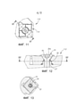
[0051] На ФИГ. 11-15 изображены вторые варианты реализации режущего инструмента 110, гнезда 114 и вставки 112. Вставка 112 выполнена с возможностью выборочного прикрепления рычагом 66 или зажимающим винтом 75. Иными словами, каждая из первой и второй зажимных выемок 126, 128 имеет соответствующие конфигурации, которые обеспечивают возможность фиксации вставки как рычагом, так и зажимающим винтом. Первая и вторая зажимные выемки 126, 128 соединены друг с другом и, тем самым образуют сквозное отверстие 27, которое соединяет противоположные первую и вторую основные поверхности 18, 20 режущей вставки 112. Каждая зажимная выемка 126, 128 имеет ту же "базовую" конфигурацию, соответствующую зажимной выемке 26, 28 из описанного выше первого варианта реализации, и, кроме того, содержит винтовую упорную поверхность 76. Согласно настоящему варианту реализации винтовая упорная поверхность 76 является конической. Согласно второму варианту реализации винтовая упорная поверхность 76 открыта к соответствующей основной упорной поверхности 24 и соединена с упорной поверхностью 32 выемки.[0051] FIG. 11-15 depict second embodiments of the
[0052] На ФИГ. 14 изображен круг, который представляет радиально наружное очертание 76a винтовой упорной поверхности 76, относящейся к первой основной поверхности 18. При проецировании на срединную плоскость P винтовые упорные поверхности 76 и радиально наружные очертания 76a, принадлежащие этим двум зажимным выемкам 126, 128, перекрываются. Таким образом, как изображено на ФИГ. 14, винтовая упорная поверхность 76 рассматриваемой зажимной выемки 126 совпадает со скрытой винтовой упорной поверхностью 76 скрытой зажимной выемки 128 и, таким образом, скрывает ее.[0052] FIG. 14 shows a circle which represents the radially
[0053] Гнездо 114 имеет выступ 78, который выступает наружу из опорной поверхности 54. Выступ 78 гнезда выполнен с возможностью обеспечения вышеуказанных преимуществ защиты от случайных ошибок. Иными словами, на виде сверху опорной поверхности 54 указанный выступ гнезда имеет удлиненную форму, которая соответствует удлиненной форме зажимных выемок 26, 126, 28, 128, для предотвращения неправильной посадки любой вставки 12, 112 в гнездо 114. Выступ 78 гнезда имеет внутреннюю резьбу и выполнен с возможностью размещения в нем зажимающего винта 75.[0053] The
[0054] Согласно некоторым вариантам реализации оба варианта реализации вставки 12, 112 являются подходящими для крепления в соответствии с вторым вариантом реализации инструмента 110.[0054] In some embodiments, both
[0055] В прикрепленном положении вставка 112 согласно второму варианту реализации посажена в гнездо 114, и зажимающий винт 75 ввинчен в выступ 78 гнезда и упирается в винтовую упорную поверхность 76.[0055] In the attached position, the
Claims (36)
Applications Claiming Priority (3)
| Application Number | Priority Date | Filing Date | Title |
|---|---|---|---|
| US201762591843P | 2017-11-29 | 2017-11-29 | |
| US62/591,843 | 2017-11-29 | ||
| PCT/IL2018/051288 WO2019106660A1 (en) | 2017-11-29 | 2018-11-27 | Double-sided cutting insert having orientation-assisting clamping recesses and cutting tool |
Publications (3)
| Publication Number | Publication Date |
|---|---|
| RU2020114322A RU2020114322A (en) | 2021-12-30 |
| RU2020114322A3 RU2020114322A3 (en) | 2021-12-30 |
| RU2765869C2 true RU2765869C2 (en) | 2022-02-04 |
Family
ID=64746599
Family Applications (1)
| Application Number | Title | Priority Date | Filing Date |
|---|---|---|---|
| RU2020114322A RU2765869C2 (en) | 2017-11-29 | 2018-11-27 | Double-sided cutting insert with orientation-facilitating clamping recesses, and cutting tool |
Country Status (11)
| Country | Link |
|---|---|
| US (1) | US11141796B2 (en) |
| EP (1) | EP3717158A1 (en) |
| JP (1) | JP7366891B2 (en) |
| KR (1) | KR102616997B1 (en) |
| CN (1) | CN111372707B (en) |
| BR (1) | BR112020010346A2 (en) |
| CA (1) | CA3083207A1 (en) |
| IL (1) | IL274245B2 (en) |
| RU (1) | RU2765869C2 (en) |
| TW (1) | TWI780271B (en) |
| WO (1) | WO2019106660A1 (en) |
Families Citing this family (3)
| Publication number | Priority date | Publication date | Assignee | Title |
|---|---|---|---|---|
| KR102393186B1 (en) * | 2018-03-28 | 2022-05-02 | 대구텍 유한책임회사 | Insert and cutting tool assembly comprising same |
| JP7024894B1 (en) * | 2021-01-13 | 2022-02-24 | 株式会社タンガロイ | Tool body |
| WO2024002527A1 (en) | 2022-06-28 | 2024-01-04 | Seco Tools Ab | A cutting tool |
Citations (6)
| Publication number | Priority date | Publication date | Assignee | Title |
|---|---|---|---|---|
| DE1246360B (en) * | 1961-12-27 | 1967-08-03 | Hertel Karl | Clamp holder with a cutting body |
| SU579102A1 (en) * | 1975-03-27 | 1977-11-05 | Савеловский Машиностроительный завод | Device for securing unsharpenable cutting plate in cutting tool holder |
| SU1255287A1 (en) * | 1985-04-03 | 1986-09-07 | Medvedev Mikhail D | Assembled cutting tool |
| SU1678546A1 (en) * | 1989-10-16 | 1991-09-23 | Научно-Производственное Объединение "Инструмент" | Cutting plate for assembled tool |
| SU1758024A1 (en) * | 1989-10-16 | 1992-08-30 | Саратовское производственное объединение "Нитрон" | Method of cleaning sewage from organic substances |
| US20080193233A1 (en) * | 2004-11-16 | 2008-08-14 | Taegutec Co | Insert Tip |
Family Cites Families (31)
| Publication number | Priority date | Publication date | Assignee | Title |
|---|---|---|---|---|
| US1255287A (en) * | 1913-06-21 | 1918-02-05 | George W Bowen | Grease-cup. |
| DE1234485B (en) * | 1957-04-09 | 1967-02-16 | Karl Hertel | Cutting body made of hard metal or ceramic cutting material |
| US3299489A (en) * | 1963-08-21 | 1967-01-24 | Espa Establishment For Securit | Tool-holder provided with reversible cutting tool, and the tool itself |
| US3314126A (en) | 1966-04-07 | 1967-04-18 | Carmet Co | Tools |
| NO135738C (en) * | 1971-05-28 | 1977-05-25 | Sandvik Ab | |
| SE394606B (en) | 1972-10-18 | 1977-07-04 | Hertel K | CUTTING TOOLS FOR CHIP SEPARATION METALWORKING |
| DE2544991C2 (en) * | 1975-10-08 | 1981-06-04 | Hertel, Karl, 8500 Nürnberg | Cutting insert for machining |
| DE2906148A1 (en) * | 1979-02-17 | 1980-08-28 | Walter Gmbh Montanwerke | CUTTING TOOL WITH REPLACEMENT INSERT |
| SE515973C2 (en) * | 2000-04-14 | 2001-11-05 | Sandvik Ab | Pin lock for inserts with bottom hole and L-shaped locking pin |
| DE10144449A1 (en) * | 2001-09-10 | 2005-03-24 | Gustav Werthwein | Cutting insert for tools for machining workpieces and tools for the use of this insert |
| US6773210B2 (en) | 2002-10-28 | 2004-08-10 | Kennametal, Inc. | Clamp pin tool holder |
| JP2004167635A (en) * | 2002-11-20 | 2004-06-17 | Mitsubishi Materials Corp | Mechanism for clamping throwaway chip, and throwaway tip used for the same |
| US7144205B2 (en) * | 2003-05-09 | 2006-12-05 | Kennametal Inc. | Insert retention screw and tool body and insert therewith |
| US7189030B2 (en) * | 2003-05-09 | 2007-03-13 | Kennametal Inc. | Cutting tool |
| CN100509225C (en) * | 2004-03-26 | 2009-07-08 | 三菱综合材料株式会社 | Clamping structure for throwaway chip |
| US20050271483A1 (en) * | 2004-06-02 | 2005-12-08 | Sandvik Ab | Indexable cutting inserts and methods for producing the same |
| US7431539B2 (en) | 2005-06-22 | 2008-10-07 | Kennametal Inc. | Clamp pin tool holder |
| US7347650B2 (en) * | 2005-10-17 | 2008-03-25 | Vichente Tipu | Cutting tool with locking pin |
| US20100129167A1 (en) * | 2008-11-21 | 2010-05-27 | Lewis Ray Morrison | Roughing cut edge insert with a finishing wiper |
| WO2010067369A2 (en) * | 2008-12-10 | 2010-06-17 | No Screw Ltd. | A cutting tool holder and a cutting insert therefor |
| KR101025355B1 (en) | 2009-01-15 | 2011-03-28 | 대구텍 유한회사 | Device for fixing cutting insert |
| KR101067161B1 (en) | 2010-01-06 | 2011-09-22 | 대구텍 유한회사 | Cutting inserts for internal grooving and toolholders for them |
| EP2554302B1 (en) * | 2010-03-31 | 2023-05-10 | Tungaloy Corporation | Cutting insert and cutting tool |
| IL208493A (en) | 2010-10-05 | 2014-02-27 | Iscar Ltd | Clamping device for a cutting insert in a tool holder |
| JP2014147977A (en) * | 2011-05-23 | 2014-08-21 | Tungaloy Corp | Cutting insert, and cutting tool using cutting insert |
| US8746115B2 (en) * | 2012-01-09 | 2014-06-10 | Iscar, Ltd. | Cutting insert having hole orientation indicia and method for making thereof |
| DE102012104082A1 (en) * | 2012-05-09 | 2013-11-14 | Walter Ag | Indexable insert for shoulder cutters |
| CA2924757C (en) * | 2013-09-03 | 2018-12-04 | No Screw Ltd. | Mounting mechanism for a cutting insert, a cutting insert therefor and a cutting tool using said insert |
| KR20150062452A (en) | 2013-11-29 | 2015-06-08 | 대구텍 유한회사 | Cutting tool assembly |
| EP3006141B1 (en) * | 2014-10-09 | 2021-09-29 | Seco Tools Ab | Double-sided, indexable turning insert and turning tool |
| US9901986B2 (en) | 2016-02-15 | 2018-02-27 | Iscar, Ltd. | Swiss turning insert with chip former arrangement comprising upwardly extending ridge |
-
2018
- 2018-11-27 CN CN201880075360.4A patent/CN111372707B/en active Active
- 2018-11-27 KR KR1020207017944A patent/KR102616997B1/en active IP Right Grant
- 2018-11-27 RU RU2020114322A patent/RU2765869C2/en active
- 2018-11-27 IL IL274245A patent/IL274245B2/en unknown
- 2018-11-27 US US16/200,796 patent/US11141796B2/en active Active
- 2018-11-27 EP EP18822506.4A patent/EP3717158A1/en active Pending
- 2018-11-27 BR BR112020010346-2A patent/BR112020010346A2/en not_active Application Discontinuation
- 2018-11-27 CA CA3083207A patent/CA3083207A1/en active Pending
- 2018-11-27 WO PCT/IL2018/051288 patent/WO2019106660A1/en active Application Filing
- 2018-11-27 JP JP2020524016A patent/JP7366891B2/en active Active
- 2018-11-29 TW TW107142594A patent/TWI780271B/en active
Patent Citations (6)
| Publication number | Priority date | Publication date | Assignee | Title |
|---|---|---|---|---|
| DE1246360B (en) * | 1961-12-27 | 1967-08-03 | Hertel Karl | Clamp holder with a cutting body |
| SU579102A1 (en) * | 1975-03-27 | 1977-11-05 | Савеловский Машиностроительный завод | Device for securing unsharpenable cutting plate in cutting tool holder |
| SU1255287A1 (en) * | 1985-04-03 | 1986-09-07 | Medvedev Mikhail D | Assembled cutting tool |
| SU1678546A1 (en) * | 1989-10-16 | 1991-09-23 | Научно-Производственное Объединение "Инструмент" | Cutting plate for assembled tool |
| SU1758024A1 (en) * | 1989-10-16 | 1992-08-30 | Саратовское производственное объединение "Нитрон" | Method of cleaning sewage from organic substances |
| US20080193233A1 (en) * | 2004-11-16 | 2008-08-14 | Taegutec Co | Insert Tip |
Also Published As
| Publication number | Publication date |
|---|---|
| BR112020010346A2 (en) | 2021-01-05 |
| RU2020114322A (en) | 2021-12-30 |
| RU2020114322A3 (en) | 2021-12-30 |
| CN111372707B (en) | 2023-02-17 |
| CA3083207A1 (en) | 2019-06-06 |
| JP7366891B2 (en) | 2023-10-23 |
| WO2019106660A1 (en) | 2019-06-06 |
| IL274245B1 (en) | 2023-08-01 |
| TW201924815A (en) | 2019-07-01 |
| KR102616997B1 (en) | 2023-12-27 |
| EP3717158A1 (en) | 2020-10-07 |
| IL274245A (en) | 2020-06-30 |
| KR20200090216A (en) | 2020-07-28 |
| CN111372707A (en) | 2020-07-03 |
| US20190160556A1 (en) | 2019-05-30 |
| US11141796B2 (en) | 2021-10-12 |
| JP2021504156A (en) | 2021-02-15 |
| IL274245B2 (en) | 2023-12-01 |
| TWI780271B (en) | 2022-10-11 |
Similar Documents
| Publication | Publication Date | Title |
|---|---|---|
| RU2765869C2 (en) | Double-sided cutting insert with orientation-facilitating clamping recesses, and cutting tool | |
| JP3065704U (en) | Tangent cutting insert | |
| JP5378507B2 (en) | Cutting insert | |
| US10005132B2 (en) | Cutting tool and cutting insert having exactly three cutting portions therefor | |
| MX2007016200A (en) | Cutting insert. | |
| JP2002542952A (en) | Cutting tool assembly and its cutting insert | |
| PL199817B1 (en) | Cutting tool and cutting insert therefor | |
| WO2013153547A1 (en) | Triangular cutting insert and cutting tool | |
| KR20100124637A (en) | Double-sided cutting insert having a circular shape and cutting tool using the same | |
| US10646927B2 (en) | Round double-sided cutting insert having a peripheral surface provided with protruding indexing latches, insert holder therefor and cutting tool | |
| US20150352646A1 (en) | Cutting insert and indexable rotary cutting tool | |
| EP2865473B1 (en) | Cutting insert, tool body on which said cutting insert may be mounted, and replaceable-blade-type ball-end mill provided therewith | |
| JP2021504156A5 (en) | ||
| EP3563956B1 (en) | Cutting insert and indexable edge rotary cutting tool | |
| US11097362B2 (en) | Cutting insert having two upper cutting edges and a lower central protuberance with four abutment walls defining an imaginary quadrilateral, and rotary cutting tool | |
| CN111906361A (en) | Cutting insert and rotary cutting tool | |
| US10974328B2 (en) | Indexable drilling insert having three tip portions and rotary cutting tool having such drilling insert centrally mounted | |
| JP2002066828A (en) | Throwaway ball end mill |