RU2754302C2 - Blood pump systems and methods - Google Patents
Blood pump systems and methods Download PDFInfo
- Publication number
- RU2754302C2 RU2754302C2 RU2017115946A RU2017115946A RU2754302C2 RU 2754302 C2 RU2754302 C2 RU 2754302C2 RU 2017115946 A RU2017115946 A RU 2017115946A RU 2017115946 A RU2017115946 A RU 2017115946A RU 2754302 C2 RU2754302 C2 RU 2754302C2
- Authority
- RU
- Russia
- Prior art keywords
- blood
- impeller
- pump
- tube
- inlet
- Prior art date
Links
- 210000004369 blood Anatomy 0.000 title claims abstract description 323
- 239000008280 blood Substances 0.000 title claims abstract description 323
- 238000000034 method Methods 0.000 title claims description 54
- 210000003462 vein Anatomy 0.000 claims abstract description 209
- 230000002093 peripheral effect Effects 0.000 claims abstract description 105
- 210000004204 blood vessel Anatomy 0.000 claims abstract description 86
- 230000017531 blood circulation Effects 0.000 claims abstract description 44
- 239000012530 fluid Substances 0.000 claims abstract description 44
- 238000005259 measurement Methods 0.000 claims abstract description 26
- 230000035485 pulse pressure Effects 0.000 claims abstract description 11
- 230000003874 surgical anastomosis Effects 0.000 claims abstract description 7
- 230000001105 regulatory effect Effects 0.000 claims abstract 3
- 238000005086 pumping Methods 0.000 claims description 36
- 230000002792 vascular Effects 0.000 claims description 31
- 238000001631 haemodialysis Methods 0.000 claims description 24
- 230000000322 hemodialysis Effects 0.000 claims description 24
- 239000000463 material Substances 0.000 claims description 21
- 229920002635 polyurethane Polymers 0.000 claims description 20
- 239000004814 polyurethane Substances 0.000 claims description 20
- 229920000295 expanded polytetrafluoroethylene Polymers 0.000 claims description 19
- 238000000576 coating method Methods 0.000 claims description 16
- 229910001000 nickel titanium Inorganic materials 0.000 claims description 14
- HLXZNVUGXRDIFK-UHFFFAOYSA-N nickel titanium Chemical compound [Ti].[Ti].[Ti].[Ti].[Ti].[Ti].[Ti].[Ti].[Ti].[Ti].[Ti].[Ni].[Ni].[Ni].[Ni].[Ni].[Ni].[Ni].[Ni].[Ni].[Ni].[Ni].[Ni].[Ni].[Ni] HLXZNVUGXRDIFK-UHFFFAOYSA-N 0.000 claims description 14
- 238000004891 communication Methods 0.000 claims description 13
- 239000011248 coating agent Substances 0.000 claims description 11
- PNEYBMLMFCGWSK-UHFFFAOYSA-N aluminium oxide Inorganic materials [O-2].[O-2].[O-2].[Al+3].[Al+3] PNEYBMLMFCGWSK-UHFFFAOYSA-N 0.000 claims description 10
- -1 polytetrafluoroethylene Polymers 0.000 claims description 10
- 229920001343 polytetrafluoroethylene Polymers 0.000 claims description 9
- 230000000845 anti-microbial effect Effects 0.000 claims description 8
- 239000004810 polytetrafluoroethylene Substances 0.000 claims description 8
- 239000000969 carrier Substances 0.000 claims description 7
- 239000003146 anticoagulant agent Substances 0.000 claims description 6
- 239000004599 antimicrobial Substances 0.000 claims description 5
- HBMJWWWQQXIZIP-UHFFFAOYSA-N silicon carbide Chemical compound [Si+]#[C-] HBMJWWWQQXIZIP-UHFFFAOYSA-N 0.000 claims description 5
- 229910010271 silicon carbide Inorganic materials 0.000 claims description 5
- HTTJABKRGRZYRN-UHFFFAOYSA-N Heparin Chemical compound OC1C(NC(=O)C)C(O)OC(COS(O)(=O)=O)C1OC1C(OS(O)(=O)=O)C(O)C(OC2C(C(OS(O)(=O)=O)C(OC3C(C(O)C(O)C(O3)C(O)=O)OS(O)(=O)=O)C(CO)O2)NS(O)(=O)=O)C(C(O)=O)O1 HTTJABKRGRZYRN-UHFFFAOYSA-N 0.000 claims description 4
- 230000002785 anti-thrombosis Effects 0.000 claims description 4
- 229960002897 heparin Drugs 0.000 claims description 4
- 229920000669 heparin Polymers 0.000 claims description 4
- 239000010935 stainless steel Substances 0.000 claims description 4
- 229910001220 stainless steel Inorganic materials 0.000 claims description 4
- 239000004696 Poly ether ether ketone Substances 0.000 claims description 3
- 229920002530 polyetherether ketone Polymers 0.000 claims description 3
- 239000012781 shape memory material Substances 0.000 claims description 3
- 230000001276 controlling effect Effects 0.000 claims 4
- MCMNRKCIXSYSNV-UHFFFAOYSA-N Zirconium dioxide Chemical compound O=[Zr]=O MCMNRKCIXSYSNV-UHFFFAOYSA-N 0.000 claims 2
- 238000005406 washing Methods 0.000 claims 2
- 230000008878 coupling Effects 0.000 abstract description 2
- 238000010168 coupling process Methods 0.000 abstract description 2
- 238000005859 coupling reaction Methods 0.000 abstract description 2
- 230000000694 effects Effects 0.000 abstract 1
- 239000000126 substance Substances 0.000 abstract 1
- 210000001367 artery Anatomy 0.000 description 137
- 230000035882 stress Effects 0.000 description 45
- 210000003128 head Anatomy 0.000 description 28
- 210000003038 endothelium Anatomy 0.000 description 15
- 210000005245 right atrium Anatomy 0.000 description 15
- 206010003226 Arteriovenous fistula Diseases 0.000 description 11
- 238000013459 approach Methods 0.000 description 10
- 238000011144 upstream manufacturing Methods 0.000 description 10
- 210000002620 vena cava superior Anatomy 0.000 description 8
- 208000020832 chronic kidney disease Diseases 0.000 description 7
- 230000006870 function Effects 0.000 description 7
- 238000005452 bending Methods 0.000 description 6
- 210000002302 brachial artery Anatomy 0.000 description 6
- 230000008859 change Effects 0.000 description 6
- 238000013461 design Methods 0.000 description 6
- 210000005259 peripheral blood Anatomy 0.000 description 6
- 239000011886 peripheral blood Substances 0.000 description 6
- 239000005020 polyethylene terephthalate Substances 0.000 description 6
- 210000003752 saphenous vein Anatomy 0.000 description 6
- 208000015181 infectious disease Diseases 0.000 description 5
- 230000000737 periodic effect Effects 0.000 description 5
- 210000001519 tissue Anatomy 0.000 description 5
- 229920004934 Dacron® Polymers 0.000 description 4
- 239000000853 adhesive Substances 0.000 description 4
- 230000001070 adhesive effect Effects 0.000 description 4
- 238000012544 monitoring process Methods 0.000 description 4
- 230000037361 pathway Effects 0.000 description 4
- 229920001296 polysiloxane Polymers 0.000 description 4
- 210000000707 wrist Anatomy 0.000 description 4
- 102000008186 Collagen Human genes 0.000 description 3
- 108010035532 Collagen Proteins 0.000 description 3
- RYECOJGRJDOGPP-UHFFFAOYSA-N Ethylurea Chemical compound CCNC(N)=O RYECOJGRJDOGPP-UHFFFAOYSA-N 0.000 description 3
- 239000004698 Polyethylene Substances 0.000 description 3
- 208000007536 Thrombosis Diseases 0.000 description 3
- 230000036772 blood pressure Effects 0.000 description 3
- 229920001436 collagen Polymers 0.000 description 3
- 238000005534 hematocrit Methods 0.000 description 3
- 238000002513 implantation Methods 0.000 description 3
- 229920003023 plastic Polymers 0.000 description 3
- 239000004033 plastic Substances 0.000 description 3
- 229920000573 polyethylene Polymers 0.000 description 3
- 229920000915 polyvinyl chloride Polymers 0.000 description 3
- 239000004800 polyvinyl chloride Substances 0.000 description 3
- 238000003860 storage Methods 0.000 description 3
- 238000007920 subcutaneous administration Methods 0.000 description 3
- 230000001960 triggered effect Effects 0.000 description 3
- 230000005641 tunneling Effects 0.000 description 3
- 208000005764 Peripheral Arterial Disease Diseases 0.000 description 2
- 208000030831 Peripheral arterial occlusive disease Diseases 0.000 description 2
- 210000001015 abdomen Anatomy 0.000 description 2
- 230000003872 anastomosis Effects 0.000 description 2
- 229960004676 antithrombotic agent Drugs 0.000 description 2
- 230000009286 beneficial effect Effects 0.000 description 2
- 210000000038 chest Anatomy 0.000 description 2
- 239000002131 composite material Substances 0.000 description 2
- 230000003247 decreasing effect Effects 0.000 description 2
- 230000010339 dilation Effects 0.000 description 2
- 238000005516 engineering process Methods 0.000 description 2
- 210000001105 femoral artery Anatomy 0.000 description 2
- 238000002594 fluoroscopy Methods 0.000 description 2
- 210000000245 forearm Anatomy 0.000 description 2
- 230000000004 hemodynamic effect Effects 0.000 description 2
- 238000003384 imaging method Methods 0.000 description 2
- 238000003780 insertion Methods 0.000 description 2
- 230000037431 insertion Effects 0.000 description 2
- 230000008338 local blood flow Effects 0.000 description 2
- 238000012986 modification Methods 0.000 description 2
- 230000004048 modification Effects 0.000 description 2
- 229910001172 neodymium magnet Inorganic materials 0.000 description 2
- 210000004197 pelvis Anatomy 0.000 description 2
- 229920000139 polyethylene terephthalate Polymers 0.000 description 2
- 238000004382 potting Methods 0.000 description 2
- 230000008569 process Effects 0.000 description 2
- 230000010349 pulsation Effects 0.000 description 2
- 210000002321 radial artery Anatomy 0.000 description 2
- 238000007634 remodeling Methods 0.000 description 2
- 230000004044 response Effects 0.000 description 2
- 239000004094 surface-active agent Substances 0.000 description 2
- 238000001356 surgical procedure Methods 0.000 description 2
- 230000001360 synchronised effect Effects 0.000 description 2
- 210000002465 tibial artery Anatomy 0.000 description 2
- 239000010936 titanium Substances 0.000 description 2
- 238000012546 transfer Methods 0.000 description 2
- 230000007704 transition Effects 0.000 description 2
- 238000002604 ultrasonography Methods 0.000 description 2
- 238000007631 vascular surgery Methods 0.000 description 2
- 102000016942 Elastin Human genes 0.000 description 1
- 108010014258 Elastin Proteins 0.000 description 1
- 102000010834 Extracellular Matrix Proteins Human genes 0.000 description 1
- 108010037362 Extracellular Matrix Proteins Proteins 0.000 description 1
- 206010020751 Hypersensitivity Diseases 0.000 description 1
- 206010020772 Hypertension Diseases 0.000 description 1
- 102000035195 Peptidases Human genes 0.000 description 1
- 108091005804 Peptidases Proteins 0.000 description 1
- 229910052774 Proactinium Inorganic materials 0.000 description 1
- 239000004365 Protease Substances 0.000 description 1
- 229910001069 Ti alloy Inorganic materials 0.000 description 1
- 239000004699 Ultra-high molecular weight polyethylene Substances 0.000 description 1
- QJVKUMXDEUEQLH-UHFFFAOYSA-N [B].[Fe].[Nd] Chemical compound [B].[Fe].[Nd] QJVKUMXDEUEQLH-UHFFFAOYSA-N 0.000 description 1
- 238000009825 accumulation Methods 0.000 description 1
- 230000032683 aging Effects 0.000 description 1
- 229910045601 alloy Inorganic materials 0.000 description 1
- 239000000956 alloy Substances 0.000 description 1
- 238000004458 analytical method Methods 0.000 description 1
- 238000002583 angiography Methods 0.000 description 1
- 238000002399 angioplasty Methods 0.000 description 1
- QVGXLLKOCUKJST-UHFFFAOYSA-N atomic oxygen Chemical compound [O] QVGXLLKOCUKJST-UHFFFAOYSA-N 0.000 description 1
- TZCXTZWJZNENPQ-UHFFFAOYSA-L barium sulfate Chemical class [Ba+2].[O-]S([O-])(=O)=O TZCXTZWJZNENPQ-UHFFFAOYSA-L 0.000 description 1
- 230000004888 barrier function Effects 0.000 description 1
- JUPQTSLXMOCDHR-UHFFFAOYSA-N benzene-1,4-diol;bis(4-fluorophenyl)methanone Chemical compound OC1=CC=C(O)C=C1.C1=CC(F)=CC=C1C(=O)C1=CC=C(F)C=C1 JUPQTSLXMOCDHR-UHFFFAOYSA-N 0.000 description 1
- 239000000560 biocompatible material Substances 0.000 description 1
- 230000008512 biological response Effects 0.000 description 1
- 230000015572 biosynthetic process Effects 0.000 description 1
- 210000000748 cardiovascular system Anatomy 0.000 description 1
- 210000004027 cell Anatomy 0.000 description 1
- 210000003477 cochlea Anatomy 0.000 description 1
- 230000000295 complement effect Effects 0.000 description 1
- 238000013170 computed tomography imaging Methods 0.000 description 1
- 230000008602 contraction Effects 0.000 description 1
- 125000004122 cyclic group Chemical group 0.000 description 1
- 230000001419 dependent effect Effects 0.000 description 1
- 238000001514 detection method Methods 0.000 description 1
- 206010012601 diabetes mellitus Diseases 0.000 description 1
- 238000010586 diagram Methods 0.000 description 1
- 238000010790 dilution Methods 0.000 description 1
- 239000012895 dilution Substances 0.000 description 1
- 238000006073 displacement reaction Methods 0.000 description 1
- 239000003814 drug Substances 0.000 description 1
- 229940079593 drug Drugs 0.000 description 1
- 229920002549 elastin Polymers 0.000 description 1
- 230000008030 elimination Effects 0.000 description 1
- 238000003379 elimination reaction Methods 0.000 description 1
- 210000002889 endothelial cell Anatomy 0.000 description 1
- 210000003989 endothelium vascular Anatomy 0.000 description 1
- 210000002744 extracellular matrix Anatomy 0.000 description 1
- 210000003414 extremity Anatomy 0.000 description 1
- 239000004744 fabric Substances 0.000 description 1
- 210000003191 femoral vein Anatomy 0.000 description 1
- 239000000446 fuel Substances 0.000 description 1
- 210000004013 groin Anatomy 0.000 description 1
- 229920001480 hydrophilic copolymer Polymers 0.000 description 1
- 230000002706 hydrostatic effect Effects 0.000 description 1
- 239000007943 implant Substances 0.000 description 1
- 238000000338 in vitro Methods 0.000 description 1
- 238000012623 in vivo measurement Methods 0.000 description 1
- 230000036512 infertility Effects 0.000 description 1
- 238000002347 injection Methods 0.000 description 1
- 239000007924 injection Substances 0.000 description 1
- 238000013152 interventional procedure Methods 0.000 description 1
- 208000028867 ischemia Diseases 0.000 description 1
- 238000010030 laminating Methods 0.000 description 1
- 239000004816 latex Substances 0.000 description 1
- 229920000126 latex Polymers 0.000 description 1
- 210000003141 lower extremity Anatomy 0.000 description 1
- 239000000314 lubricant Substances 0.000 description 1
- 210000002540 macrophage Anatomy 0.000 description 1
- 238000002595 magnetic resonance imaging Methods 0.000 description 1
- 238000004519 manufacturing process Methods 0.000 description 1
- 239000003550 marker Substances 0.000 description 1
- 239000011159 matrix material Substances 0.000 description 1
- 230000035800 maturation Effects 0.000 description 1
- 230000001785 maturational effect Effects 0.000 description 1
- 238000010297 mechanical methods and process Methods 0.000 description 1
- 230000007246 mechanism Effects 0.000 description 1
- 230000001404 mediated effect Effects 0.000 description 1
- 229920002529 medical grade silicone Polymers 0.000 description 1
- 238000002844 melting Methods 0.000 description 1
- 230000008018 melting Effects 0.000 description 1
- 229910052751 metal Inorganic materials 0.000 description 1
- 239000002184 metal Substances 0.000 description 1
- 239000002991 molded plastic Substances 0.000 description 1
- 210000001616 monocyte Anatomy 0.000 description 1
- 210000000056 organ Anatomy 0.000 description 1
- TWNQGVIAIRXVLR-UHFFFAOYSA-N oxo(oxoalumanyloxy)alumane Chemical compound O=[Al]O[Al]=O TWNQGVIAIRXVLR-UHFFFAOYSA-N 0.000 description 1
- 229910052760 oxygen Inorganic materials 0.000 description 1
- 239000001301 oxygen Substances 0.000 description 1
- 238000004806 packaging method and process Methods 0.000 description 1
- 230000008447 perception Effects 0.000 description 1
- 230000002085 persistent effect Effects 0.000 description 1
- 229920000728 polyester Polymers 0.000 description 1
- 229920000642 polymer Polymers 0.000 description 1
- 210000003137 popliteal artery Anatomy 0.000 description 1
- 230000036316 preload Effects 0.000 description 1
- 230000000750 progressive effect Effects 0.000 description 1
- 229910001285 shape-memory alloy Inorganic materials 0.000 description 1
- 230000035939 shock Effects 0.000 description 1
- 230000007727 signaling mechanism Effects 0.000 description 1
- 229910052710 silicon Inorganic materials 0.000 description 1
- 239000010703 silicon Substances 0.000 description 1
- 229920002379 silicone rubber Polymers 0.000 description 1
- 229910052709 silver Inorganic materials 0.000 description 1
- 239000004332 silver Substances 0.000 description 1
- 230000003595 spectral effect Effects 0.000 description 1
- 238000010183 spectrum analysis Methods 0.000 description 1
- 238000010561 standard procedure Methods 0.000 description 1
- 230000000638 stimulation Effects 0.000 description 1
- 238000003786 synthesis reaction Methods 0.000 description 1
- 229910052719 titanium Inorganic materials 0.000 description 1
- 210000002559 ulnar artery Anatomy 0.000 description 1
- 229920000785 ultra high molecular weight polyethylene Polymers 0.000 description 1
- 238000012285 ultrasound imaging Methods 0.000 description 1
- 229910052720 vanadium Inorganic materials 0.000 description 1
- 210000004509 vascular smooth muscle cell Anatomy 0.000 description 1
- 210000002073 venous valve Anatomy 0.000 description 1
- 230000002861 ventricular Effects 0.000 description 1
- 239000002023 wood Substances 0.000 description 1
Images
Classifications
-
- A—HUMAN NECESSITIES
- A61—MEDICAL OR VETERINARY SCIENCE; HYGIENE
- A61M—DEVICES FOR INTRODUCING MEDIA INTO, OR ONTO, THE BODY; DEVICES FOR TRANSDUCING BODY MEDIA OR FOR TAKING MEDIA FROM THE BODY; DEVICES FOR PRODUCING OR ENDING SLEEP OR STUPOR
- A61M1/00—Suction or pumping devices for medical purposes; Devices for carrying-off, for treatment of, or for carrying-over, body-liquids; Drainage systems
- A61M1/36—Other treatment of blood in a by-pass of the natural circulatory system, e.g. temperature adaptation, irradiation ; Extra-corporeal blood circuits
- A61M1/3607—Regulation parameters
- A61M1/3609—Physical characteristics of the blood, e.g. haematocrit, urea
-
- A—HUMAN NECESSITIES
- A61—MEDICAL OR VETERINARY SCIENCE; HYGIENE
- A61M—DEVICES FOR INTRODUCING MEDIA INTO, OR ONTO, THE BODY; DEVICES FOR TRANSDUCING BODY MEDIA OR FOR TAKING MEDIA FROM THE BODY; DEVICES FOR PRODUCING OR ENDING SLEEP OR STUPOR
- A61M60/00—Blood pumps; Devices for mechanical circulatory actuation; Balloon pumps for circulatory assistance
- A61M60/50—Details relating to control
- A61M60/508—Electronic control means, e.g. for feedback regulation
- A61M60/515—Regulation using real-time patient data
- A61M60/523—Regulation using real-time patient data using blood flow data, e.g. from blood flow transducers
-
- A—HUMAN NECESSITIES
- A61—MEDICAL OR VETERINARY SCIENCE; HYGIENE
- A61B—DIAGNOSIS; SURGERY; IDENTIFICATION
- A61B5/00—Measuring for diagnostic purposes; Identification of persons
- A61B5/02—Detecting, measuring or recording pulse, heart rate, blood pressure or blood flow; Combined pulse/heart-rate/blood pressure determination; Evaluating a cardiovascular condition not otherwise provided for, e.g. using combinations of techniques provided for in this group with electrocardiography or electroauscultation; Heart catheters for measuring blood pressure
- A61B5/02028—Determining haemodynamic parameters not otherwise provided for, e.g. cardiac contractility or left ventricular ejection fraction
- A61B5/02035—Determining blood viscosity
-
- A—HUMAN NECESSITIES
- A61—MEDICAL OR VETERINARY SCIENCE; HYGIENE
- A61M—DEVICES FOR INTRODUCING MEDIA INTO, OR ONTO, THE BODY; DEVICES FOR TRANSDUCING BODY MEDIA OR FOR TAKING MEDIA FROM THE BODY; DEVICES FOR PRODUCING OR ENDING SLEEP OR STUPOR
- A61M1/00—Suction or pumping devices for medical purposes; Devices for carrying-off, for treatment of, or for carrying-over, body-liquids; Drainage systems
- A61M1/14—Dialysis systems; Artificial kidneys; Blood oxygenators ; Reciprocating systems for treatment of body fluids, e.g. single needle systems for hemofiltration or pheresis
-
- A—HUMAN NECESSITIES
- A61—MEDICAL OR VETERINARY SCIENCE; HYGIENE
- A61M—DEVICES FOR INTRODUCING MEDIA INTO, OR ONTO, THE BODY; DEVICES FOR TRANSDUCING BODY MEDIA OR FOR TAKING MEDIA FROM THE BODY; DEVICES FOR PRODUCING OR ENDING SLEEP OR STUPOR
- A61M1/00—Suction or pumping devices for medical purposes; Devices for carrying-off, for treatment of, or for carrying-over, body-liquids; Drainage systems
- A61M1/36—Other treatment of blood in a by-pass of the natural circulatory system, e.g. temperature adaptation, irradiation ; Extra-corporeal blood circuits
- A61M1/3621—Extra-corporeal blood circuits
- A61M1/3639—Blood pressure control, pressure transducers specially adapted therefor
-
- A—HUMAN NECESSITIES
- A61—MEDICAL OR VETERINARY SCIENCE; HYGIENE
- A61M—DEVICES FOR INTRODUCING MEDIA INTO, OR ONTO, THE BODY; DEVICES FOR TRANSDUCING BODY MEDIA OR FOR TAKING MEDIA FROM THE BODY; DEVICES FOR PRODUCING OR ENDING SLEEP OR STUPOR
- A61M1/00—Suction or pumping devices for medical purposes; Devices for carrying-off, for treatment of, or for carrying-over, body-liquids; Drainage systems
- A61M1/36—Other treatment of blood in a by-pass of the natural circulatory system, e.g. temperature adaptation, irradiation ; Extra-corporeal blood circuits
- A61M1/3621—Extra-corporeal blood circuits
- A61M1/3653—Interfaces between patient blood circulation and extra-corporal blood circuit
- A61M1/3655—Arterio-venous shunts or fistulae
-
- A—HUMAN NECESSITIES
- A61—MEDICAL OR VETERINARY SCIENCE; HYGIENE
- A61M—DEVICES FOR INTRODUCING MEDIA INTO, OR ONTO, THE BODY; DEVICES FOR TRANSDUCING BODY MEDIA OR FOR TAKING MEDIA FROM THE BODY; DEVICES FOR PRODUCING OR ENDING SLEEP OR STUPOR
- A61M1/00—Suction or pumping devices for medical purposes; Devices for carrying-off, for treatment of, or for carrying-over, body-liquids; Drainage systems
- A61M1/36—Other treatment of blood in a by-pass of the natural circulatory system, e.g. temperature adaptation, irradiation ; Extra-corporeal blood circuits
- A61M1/3621—Extra-corporeal blood circuits
- A61M1/3653—Interfaces between patient blood circulation and extra-corporal blood circuit
- A61M1/3659—Cannulae pertaining to extracorporeal circulation
-
- A—HUMAN NECESSITIES
- A61—MEDICAL OR VETERINARY SCIENCE; HYGIENE
- A61M—DEVICES FOR INTRODUCING MEDIA INTO, OR ONTO, THE BODY; DEVICES FOR TRANSDUCING BODY MEDIA OR FOR TAKING MEDIA FROM THE BODY; DEVICES FOR PRODUCING OR ENDING SLEEP OR STUPOR
- A61M60/00—Blood pumps; Devices for mechanical circulatory actuation; Balloon pumps for circulatory assistance
- A61M60/10—Location thereof with respect to the patient's body
- A61M60/104—Extracorporeal pumps, i.e. the blood being pumped outside the patient's body
- A61M60/109—Extracorporeal pumps, i.e. the blood being pumped outside the patient's body incorporated within extracorporeal blood circuits or systems
-
- A—HUMAN NECESSITIES
- A61—MEDICAL OR VETERINARY SCIENCE; HYGIENE
- A61M—DEVICES FOR INTRODUCING MEDIA INTO, OR ONTO, THE BODY; DEVICES FOR TRANSDUCING BODY MEDIA OR FOR TAKING MEDIA FROM THE BODY; DEVICES FOR PRODUCING OR ENDING SLEEP OR STUPOR
- A61M60/00—Blood pumps; Devices for mechanical circulatory actuation; Balloon pumps for circulatory assistance
- A61M60/20—Type thereof
- A61M60/205—Non-positive displacement blood pumps
- A61M60/216—Non-positive displacement blood pumps including a rotating member acting on the blood, e.g. impeller
- A61M60/226—Non-positive displacement blood pumps including a rotating member acting on the blood, e.g. impeller the blood flow through the rotating member having mainly radial components
- A61M60/232—Centrifugal pumps
-
- A—HUMAN NECESSITIES
- A61—MEDICAL OR VETERINARY SCIENCE; HYGIENE
- A61M—DEVICES FOR INTRODUCING MEDIA INTO, OR ONTO, THE BODY; DEVICES FOR TRANSDUCING BODY MEDIA OR FOR TAKING MEDIA FROM THE BODY; DEVICES FOR PRODUCING OR ENDING SLEEP OR STUPOR
- A61M60/00—Blood pumps; Devices for mechanical circulatory actuation; Balloon pumps for circulatory assistance
- A61M60/30—Medical purposes thereof other than the enhancement of the cardiac output
- A61M60/34—Medical purposes thereof other than the enhancement of the cardiac output for enhancement of circulation to the extremities, e.g. the feet
-
- A—HUMAN NECESSITIES
- A61—MEDICAL OR VETERINARY SCIENCE; HYGIENE
- A61M—DEVICES FOR INTRODUCING MEDIA INTO, OR ONTO, THE BODY; DEVICES FOR TRANSDUCING BODY MEDIA OR FOR TAKING MEDIA FROM THE BODY; DEVICES FOR PRODUCING OR ENDING SLEEP OR STUPOR
- A61M60/00—Blood pumps; Devices for mechanical circulatory actuation; Balloon pumps for circulatory assistance
- A61M60/30—Medical purposes thereof other than the enhancement of the cardiac output
- A61M60/36—Medical purposes thereof other than the enhancement of the cardiac output for specific blood treatment; for specific therapy
- A61M60/37—Haemodialysis, haemofiltration or diafiltration
-
- A—HUMAN NECESSITIES
- A61—MEDICAL OR VETERINARY SCIENCE; HYGIENE
- A61M—DEVICES FOR INTRODUCING MEDIA INTO, OR ONTO, THE BODY; DEVICES FOR TRANSDUCING BODY MEDIA OR FOR TAKING MEDIA FROM THE BODY; DEVICES FOR PRODUCING OR ENDING SLEEP OR STUPOR
- A61M60/00—Blood pumps; Devices for mechanical circulatory actuation; Balloon pumps for circulatory assistance
- A61M60/40—Details relating to driving
- A61M60/403—Details relating to driving for non-positive displacement blood pumps
- A61M60/408—Details relating to driving for non-positive displacement blood pumps the force acting on the blood contacting member being mechanical, e.g. transmitted by a shaft or cable
- A61M60/411—Details relating to driving for non-positive displacement blood pumps the force acting on the blood contacting member being mechanical, e.g. transmitted by a shaft or cable generated by an electromotor
- A61M60/414—Details relating to driving for non-positive displacement blood pumps the force acting on the blood contacting member being mechanical, e.g. transmitted by a shaft or cable generated by an electromotor transmitted by a rotating cable, e.g. for blood pumps mounted on a catheter
-
- A—HUMAN NECESSITIES
- A61—MEDICAL OR VETERINARY SCIENCE; HYGIENE
- A61M—DEVICES FOR INTRODUCING MEDIA INTO, OR ONTO, THE BODY; DEVICES FOR TRANSDUCING BODY MEDIA OR FOR TAKING MEDIA FROM THE BODY; DEVICES FOR PRODUCING OR ENDING SLEEP OR STUPOR
- A61M60/00—Blood pumps; Devices for mechanical circulatory actuation; Balloon pumps for circulatory assistance
- A61M60/40—Details relating to driving
- A61M60/403—Details relating to driving for non-positive displacement blood pumps
- A61M60/422—Details relating to driving for non-positive displacement blood pumps the force acting on the blood contacting member being electromagnetic, e.g. using canned motor pumps
-
- A—HUMAN NECESSITIES
- A61—MEDICAL OR VETERINARY SCIENCE; HYGIENE
- A61M—DEVICES FOR INTRODUCING MEDIA INTO, OR ONTO, THE BODY; DEVICES FOR TRANSDUCING BODY MEDIA OR FOR TAKING MEDIA FROM THE BODY; DEVICES FOR PRODUCING OR ENDING SLEEP OR STUPOR
- A61M60/00—Blood pumps; Devices for mechanical circulatory actuation; Balloon pumps for circulatory assistance
- A61M60/50—Details relating to control
- A61M60/508—Electronic control means, e.g. for feedback regulation
- A61M60/515—Regulation using real-time patient data
- A61M60/531—Regulation using real-time patient data using blood pressure data, e.g. from blood pressure sensors
-
- A—HUMAN NECESSITIES
- A61—MEDICAL OR VETERINARY SCIENCE; HYGIENE
- A61M—DEVICES FOR INTRODUCING MEDIA INTO, OR ONTO, THE BODY; DEVICES FOR TRANSDUCING BODY MEDIA OR FOR TAKING MEDIA FROM THE BODY; DEVICES FOR PRODUCING OR ENDING SLEEP OR STUPOR
- A61M60/00—Blood pumps; Devices for mechanical circulatory actuation; Balloon pumps for circulatory assistance
- A61M60/50—Details relating to control
- A61M60/508—Electronic control means, e.g. for feedback regulation
- A61M60/538—Regulation using real-time blood pump operational parameter data, e.g. motor current
-
- A—HUMAN NECESSITIES
- A61—MEDICAL OR VETERINARY SCIENCE; HYGIENE
- A61M—DEVICES FOR INTRODUCING MEDIA INTO, OR ONTO, THE BODY; DEVICES FOR TRANSDUCING BODY MEDIA OR FOR TAKING MEDIA FROM THE BODY; DEVICES FOR PRODUCING OR ENDING SLEEP OR STUPOR
- A61M60/00—Blood pumps; Devices for mechanical circulatory actuation; Balloon pumps for circulatory assistance
- A61M60/80—Constructional details other than related to driving
- A61M60/802—Constructional details other than related to driving of non-positive displacement blood pumps
- A61M60/804—Impellers
- A61M60/806—Vanes or blades
-
- A—HUMAN NECESSITIES
- A61—MEDICAL OR VETERINARY SCIENCE; HYGIENE
- A61M—DEVICES FOR INTRODUCING MEDIA INTO, OR ONTO, THE BODY; DEVICES FOR TRANSDUCING BODY MEDIA OR FOR TAKING MEDIA FROM THE BODY; DEVICES FOR PRODUCING OR ENDING SLEEP OR STUPOR
- A61M60/00—Blood pumps; Devices for mechanical circulatory actuation; Balloon pumps for circulatory assistance
- A61M60/80—Constructional details other than related to driving
- A61M60/802—Constructional details other than related to driving of non-positive displacement blood pumps
- A61M60/818—Bearings
- A61M60/825—Contact bearings, e.g. ball-and-cup or pivot bearings
-
- G—PHYSICS
- G01—MEASURING; TESTING
- G01N—INVESTIGATING OR ANALYSING MATERIALS BY DETERMINING THEIR CHEMICAL OR PHYSICAL PROPERTIES
- G01N11/00—Investigating flow properties of materials, e.g. viscosity, plasticity; Analysing materials by determining flow properties
- G01N11/02—Investigating flow properties of materials, e.g. viscosity, plasticity; Analysing materials by determining flow properties by measuring flow of the material
- G01N11/04—Investigating flow properties of materials, e.g. viscosity, plasticity; Analysing materials by determining flow properties by measuring flow of the material through a restricted passage, e.g. tube, aperture
- G01N11/06—Investigating flow properties of materials, e.g. viscosity, plasticity; Analysing materials by determining flow properties by measuring flow of the material through a restricted passage, e.g. tube, aperture by timing the outflow of a known quantity
-
- A—HUMAN NECESSITIES
- A61—MEDICAL OR VETERINARY SCIENCE; HYGIENE
- A61M—DEVICES FOR INTRODUCING MEDIA INTO, OR ONTO, THE BODY; DEVICES FOR TRANSDUCING BODY MEDIA OR FOR TAKING MEDIA FROM THE BODY; DEVICES FOR PRODUCING OR ENDING SLEEP OR STUPOR
- A61M2205/00—General characteristics of the apparatus
- A61M2205/18—General characteristics of the apparatus with alarm
-
- A—HUMAN NECESSITIES
- A61—MEDICAL OR VETERINARY SCIENCE; HYGIENE
- A61M—DEVICES FOR INTRODUCING MEDIA INTO, OR ONTO, THE BODY; DEVICES FOR TRANSDUCING BODY MEDIA OR FOR TAKING MEDIA FROM THE BODY; DEVICES FOR PRODUCING OR ENDING SLEEP OR STUPOR
- A61M2205/00—General characteristics of the apparatus
- A61M2205/33—Controlling, regulating or measuring
- A61M2205/3331—Pressure; Flow
- A61M2205/3334—Measuring or controlling the flow rate
-
- A—HUMAN NECESSITIES
- A61—MEDICAL OR VETERINARY SCIENCE; HYGIENE
- A61M—DEVICES FOR INTRODUCING MEDIA INTO, OR ONTO, THE BODY; DEVICES FOR TRANSDUCING BODY MEDIA OR FOR TAKING MEDIA FROM THE BODY; DEVICES FOR PRODUCING OR ENDING SLEEP OR STUPOR
- A61M2205/00—General characteristics of the apparatus
- A61M2205/33—Controlling, regulating or measuring
- A61M2205/3331—Pressure; Flow
- A61M2205/3344—Measuring or controlling pressure at the body treatment site
-
- A—HUMAN NECESSITIES
- A61—MEDICAL OR VETERINARY SCIENCE; HYGIENE
- A61M—DEVICES FOR INTRODUCING MEDIA INTO, OR ONTO, THE BODY; DEVICES FOR TRANSDUCING BODY MEDIA OR FOR TAKING MEDIA FROM THE BODY; DEVICES FOR PRODUCING OR ENDING SLEEP OR STUPOR
- A61M2205/00—General characteristics of the apparatus
- A61M2205/50—General characteristics of the apparatus with microprocessors or computers
- A61M2205/502—User interfaces, e.g. screens or keyboards
-
- A—HUMAN NECESSITIES
- A61—MEDICAL OR VETERINARY SCIENCE; HYGIENE
- A61M—DEVICES FOR INTRODUCING MEDIA INTO, OR ONTO, THE BODY; DEVICES FOR TRANSDUCING BODY MEDIA OR FOR TAKING MEDIA FROM THE BODY; DEVICES FOR PRODUCING OR ENDING SLEEP OR STUPOR
- A61M2205/00—General characteristics of the apparatus
- A61M2205/82—Internal energy supply devices
-
- A—HUMAN NECESSITIES
- A61—MEDICAL OR VETERINARY SCIENCE; HYGIENE
- A61M—DEVICES FOR INTRODUCING MEDIA INTO, OR ONTO, THE BODY; DEVICES FOR TRANSDUCING BODY MEDIA OR FOR TAKING MEDIA FROM THE BODY; DEVICES FOR PRODUCING OR ENDING SLEEP OR STUPOR
- A61M60/00—Blood pumps; Devices for mechanical circulatory actuation; Balloon pumps for circulatory assistance
- A61M60/10—Location thereof with respect to the patient's body
- A61M60/122—Implantable pumps or pumping devices, i.e. the blood being pumped inside the patient's body
- A61M60/126—Implantable pumps or pumping devices, i.e. the blood being pumped inside the patient's body implantable via, into, inside, in line, branching on, or around a blood vessel
- A61M60/148—Implantable pumps or pumping devices, i.e. the blood being pumped inside the patient's body implantable via, into, inside, in line, branching on, or around a blood vessel in line with a blood vessel using resection or like techniques, e.g. permanent endovascular heart assist devices
-
- A—HUMAN NECESSITIES
- A61—MEDICAL OR VETERINARY SCIENCE; HYGIENE
- A61M—DEVICES FOR INTRODUCING MEDIA INTO, OR ONTO, THE BODY; DEVICES FOR TRANSDUCING BODY MEDIA OR FOR TAKING MEDIA FROM THE BODY; DEVICES FOR PRODUCING OR ENDING SLEEP OR STUPOR
- A61M60/00—Blood pumps; Devices for mechanical circulatory actuation; Balloon pumps for circulatory assistance
- A61M60/20—Type thereof
- A61M60/205—Non-positive displacement blood pumps
-
- A—HUMAN NECESSITIES
- A61—MEDICAL OR VETERINARY SCIENCE; HYGIENE
- A61M—DEVICES FOR INTRODUCING MEDIA INTO, OR ONTO, THE BODY; DEVICES FOR TRANSDUCING BODY MEDIA OR FOR TAKING MEDIA FROM THE BODY; DEVICES FOR PRODUCING OR ENDING SLEEP OR STUPOR
- A61M60/00—Blood pumps; Devices for mechanical circulatory actuation; Balloon pumps for circulatory assistance
- A61M60/80—Constructional details other than related to driving
- A61M60/802—Constructional details other than related to driving of non-positive displacement blood pumps
- A61M60/818—Bearings
-
- A—HUMAN NECESSITIES
- A61—MEDICAL OR VETERINARY SCIENCE; HYGIENE
- A61M—DEVICES FOR INTRODUCING MEDIA INTO, OR ONTO, THE BODY; DEVICES FOR TRANSDUCING BODY MEDIA OR FOR TAKING MEDIA FROM THE BODY; DEVICES FOR PRODUCING OR ENDING SLEEP OR STUPOR
- A61M60/00—Blood pumps; Devices for mechanical circulatory actuation; Balloon pumps for circulatory assistance
- A61M60/80—Constructional details other than related to driving
- A61M60/855—Constructional details other than related to driving of implantable pumps or pumping devices
- A61M60/857—Implantable blood tubes
Abstract
Description
По данной заявке испрашивают приоритет патентной заявки США № 61/564,671, которая озаглавлена «Blood Pump Systems and Methods», которая подана 29 ноября 2011 года, и испрашивают приоритет патентной заявки США № 61/524,761, которая озаглавлена «Blood Pump Systems and Methods», которая подана 17 августа 2011 года, которая является частичным продолжением патентной заявки США № 13/030,054, которая озаглавлена «System and Method to Increase the Overall Diameter of Veins», которая подана 17 февраля 2011 года, по которой испрашивают приоритет предварительной заявки США № 61/305,508, которая озаглавлена «System and Method to Increase the Overall Diameter of Veins», которая подана 17 февраля 2010 года и связана с совместно рассматриваемой совместно поданной международной патентной заявкой PCT № PCT/US12/50978, которая озаглавлена «System and Method to Increase the Overall Diameter of Veins and Arteries», которая подана 15 августа 2012 года и связана с совместно рассматриваемой патентной заявкой США № 61/524,759, которая озаглавлена «System and Method to Increase the Overall Diameter of Veins and Arteries», которая подана 17 августа 2011 года, и патентной заявкой США № 61/561,859, которая озаглавлена «System and Method to Increase the Overall Diameter of Veins and Arteries», которая подана 19 ноября 2011 года, все они включены посредством ссылки во всей своей полноте.This application claims the priority of US Patent Application No. 61 / 564,671, which is entitled "Blood Pump Systems and Methods," which filed November 29, 2011, and claims the priority of US Patent Application No. 61 / 524,761, which is entitled "Blood Pump Systems and Methods." which is filed Aug. 17, 2011, which is a sequel to U.S. Patent Application No. 13 / 030,054, which is entitled "System and Method to Increase the Overall Diameter of Veins," which filed Feb. 17, 2011, which claims the priority of U.S. Provisional Application No. 61 / 305,508, which is entitled "System and Method to Increase the Overall Diameter of Veins," which filed February 17, 2010, and is related to PCT Co-pending International Patent Application No. PCT / US12 / 50978, which is entitled "System and Method to Increase the Overall Diameter of Veins and Arteries ”, which was filed August 15, 2012 and is related to a co-pending patent application US No. 61 / 524,759, which is entitled "System and Method to Increase the Overall Diameter of Veins and Arteries", which is filed August 17, 2011, and US patent application No. 61 / 561,859, which is entitled "System and Method to Increase the Overall Diameter of Veins and Arteries, filed November 19, 2011, all of which are incorporated by reference in their entirety.
ОБЛАСТЬ ИЗОБРЕТЕНИЯFIELD OF THE INVENTION
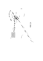
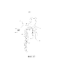
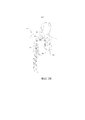
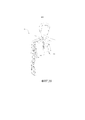
Настоящее изобретение относится к системе кровяного насоса, которая содержит насос, трубки, блок управления и источник питания, посредством чего систему можно использовать, чтобы постоянно увеличивать локальный поток крови в артериях и венах пациента. В частности, это изобретение можно использовать для постоянного увеличения наружного диаметра и диаметра просвета вен и артерий у пациентов, нуждающихся в месте сосудистого доступа для гемодиализа, шунтирующем трансплантате или хирургическом вмешательстве или процедуре другого типа, где вены или артерии большего диаметра являются желаемыми. Это изобретение также можно использовать для обеспечения увеличенного локального потока крови к органам и тканям, нуждающимся в этом, таким как нижние конечности пациента с заболеванием периферических артерий (ЗПА). The present invention relates to a blood pump system that includes a pump, tubes, a control unit and a power supply, whereby the system can be used to continuously increase the local blood flow in the arteries and veins of a patient. In particular, this invention can be used to permanently increase the outer diameter and diameter of the lumen of veins and arteries in patients requiring a vascular access site for hemodialysis, bypass graft or surgery or other type of procedure where veins or arteries of a larger diameter are desired. This invention can also be used to provide increased local blood flow to organs and tissues in need, such as the lower limbs of a patient with peripheral arterial disease (PAD).
УРОВЕНЬ ТЕХНИКИ LEVEL OF TECHNOLOGY
В Соединенных Штатах существует более полумиллиона пациентов с хронической почечной недостаточностью (CKD), причем более 100000 новых пациентов с CKD появляется каждый год. Прогнозируют увеличение распространенности в популяции на четыре процента ежегодно из-за таких движущих факторов, как, например, высокое кровяное давление, диабет и старение популяции. There are over half a million chronic kidney disease (CKD) patients in the United States, with over 100,000 new CKD patients appearing each year. Population prevalence is predicted to increase by four percent annually due to driving factors such as high blood pressure, diabetes and population aging.
Гемодиализ представляет собой лечение, предпочтительное для 92% пациентов с CKD, поскольку без гемодиализа или некоторых других форм лечения эти пациенты с CKD погибнут. Сосудистую систему типичного пациента с CKD, проходящего лечение гемодиализом, нужно соединять с аппаратом для гемодиализа от двух до трех раз в неделю. Для гемодиализа существует три возможных обыкновенных места сосудистого доступа. Предпочтительное возможное место доступа представляет собой артериовенозную фистулу (АВФ), которая представляет собой непосредственное хирургически созданное соединение между артерией и веной, предпочтительно на запястье или альтернативно на предплечье, верхней части руки, ноге или в паху. Другое возможное место доступа представляет собой артериовенозный трансплантат (АВТ), который представляет собой хирургически созданное соединение между артерией и веной с использованием промежуточной синтетической трубки. Последним основным возможным местом доступа является катетер, вставленный в большую вену на шее, в грудной клетке, ноге или другом анатомическом местоположении. Hemodialysis is the treatment of choice for 92% of CKD patients because without hemodialysis or some other form of treatment, these CKD patients will die. The vascular system of a typical CKD patient undergoing hemodialysis treatment should be connected to a hemodialysis machine two to three times a week. There are three possible common vascular access sites for hemodialysis. A preferred potential access site is an arteriovenous fistula (AVF), which is a direct surgically created connection between an artery and vein, preferably on the wrist or alternatively on the forearm, upper arm, leg, or groin. Another possible access site is an arteriovenous graft (AVT), which is a surgically created connection between an artery and a vein using an intermediate synthetic tube. The last major possible access site is a catheter inserted into a large vein in the neck, chest, leg, or other anatomical location.
Пациенты с АВФ имеют более низкую болезненность, более низкую смертность и более низкие расходы на уход по сравнению с пациентами с АВТ или катетером; следовательно, АВФ на запястье представляет собой предпочтительную форму сосудистого доступа для гемодиализа. Пациенты с АВТ или катетером имеют по существу более высокие уровни инфекции и смерти, чем пациенты, которые имеют АВФ, причем пациенты с катетерами имеют наихудшие исходы. Кроме того, пациенты, которые имеют АВТ или катетер, имеют более высокие средние расходы на уход, причем пациенты с катетерами имеют самые высокие расходы. Если пациент подходит для АВФ, запястье или предплечье в общем, является предпочтительным относительно АВФ на верхней части руки из-за более высокого уровня ишемии руки и в общем, более коротких и более глубоких сегментов вены в верхней части руки. Patients with AVF have lower morbidity, lower mortality, and lower care costs compared to patients with AVT or catheter; therefore, the wrist AVF is the preferred form of vascular access for hemodialysis. Patients with AVTs or catheters have substantially higher rates of infection and death than patients who have AVFs, with patients with catheters having the worst outcomes. In addition, patients who have an AVT or catheter have higher average care costs, with patients with catheters having the highest costs. If the patient is suitable for an AVF, wrist or forearm in general is preferred over an upper arm AVF due to the higher level of arm ischemia and in general, shorter and deeper vein segments in the upper arm.
К сожалению, приблизительно 85 процентов пациентов непригодны для АВФ на запястье, главным образом из-за слишком малых диаметров вен и артерий. Кроме того, приблизительно 60 процентов всех созданных АВФ нельзя использовать без дополнительных хирургических и интервенционных процедур из-за возникновения того, что обыкновенно обозначают как «невозможность созревания», которая коррелирует с малым диаметром вены и артерии. Доступность вен и артерий с более крупными диаметрами коррелирует с более высокой приемлемостью АВФ и низким уровнем невозможности созревания. Unfortunately, approximately 85 percent of patients are unsuitable for an AVF on the wrist, mainly due to too small diameters of veins and arteries. In addition, approximately 60 percent of all created AVFs cannot be used without additional surgical and interventional procedures due to the occurrence of what is commonly referred to as “maturational failure”, which correlates with the small diameter of the vein and artery. The availability of larger diameter veins and arteries correlates with higher AVF acceptability and a lower incidence of maturation.
В настоящее время, существует несколько возможностей перманентно и постоянно увеличивать диаметр вены или артерии. Все существующие способы используют механические способы дилятации, такие как баллонная ангиопластика, которые могут вести к повреждению вен или артерий. Поскольку пациент должен иметь периферические вены и артерии определенного размера, чтобы врач создал АВФ, желательно имеет способ и систему для постоянного и перманентного увеличения размера или диаметра периферических вен или артерий.Currently, there are several possibilities to permanently and continuously increase the diameter of a vein or artery. All existing methods use mechanical methods of dilation, such as balloon angioplasty, which can damage the veins or arteries. Since the patient must have a certain size of peripheral veins and arteries for the physician to create an AVF, it is desirable to have a method and system for permanently and permanently increasing the size or diameter of the peripheral veins or arteries.
В настоящее время существуют небольшие «сердечные насосы». Однако, такие насосы дороги, не имеют размеров и не разработаны для использования в конечности. По существу, существует необходимость в данной области в системах, компонентах и способах для увеличения диаметра периферических вен и артерий при разумных расходах. Дополнительно, существует необходимость в насосном устройстве, которое может увеличивать диаметр периферических вен и артерий.Small "heart pumps" exist nowadays. However, such pumps are expensive, not dimensioned, and not designed for use in an extremity. As such, there is a need in the art for systems, components and methods for increasing the diameter of peripheral veins and arteries at a reasonable cost. Additionally, there is a need for a pumping device that can increase the diameter of peripheral veins and arteries.
СУЩНОСТЬ ИЗОБРЕТЕНИЯSUMMARY OF THE INVENTION
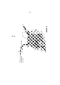
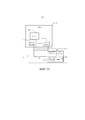
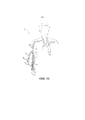
Настоящая заявка относится к системе кровяного насоса для использования в увеличении диаметра вен и артерий, предпочтительно периферических вен и артерий. Система функционирует для того, чтобы перемещать кровь таким образом, чтобы вызывать увеличение диаметра вены или артерии. Это можно выполнять посредством выброса («выталкивания») крови в вену или артерию или посредством удаления («всасывания») крови из вены или артерии. Посредством любого способа система увеличивает поток крови в сосуде, что в конечном итоге ведет к постоянному увеличению диаметра сосуда. По существу, система и, более конкретно, насос используют механическое средство для того, чтобы активировать пути биологических реакций, что ведет к увеличению или «ремоделированию» вен или артерий. Система имеет кровяной насос, трубки для того, чтобы нести кровь к кровяному насосу и от него, систему управления для того, чтобы осуществлять мониторинг кровяного насоса и модифицировать работу кровяного насоса, и источник мощности. По существу, система содержит группу элементов, которые можно, например, вставлять в артерию одним концом и в вену другим, посредством чего, когда активируют, кровь перекачивают с такой скоростью, что напряжение сдвига у стенки (НСС) на эндотелии вены, артерии или обеих повышают в течение периода времени, достаточного для того, чтобы вызывать постоянное увеличение вены или артерии. Любой из множества насосов можно использовать при условии, что насосом можно управлять для того, чтобы получать желаемое увеличение диаметра кровеносного сосуда. The present application relates to a blood pump system for use in enlarging the diameter of veins and arteries, preferably peripheral veins and arteries. The system functions to move blood in such a way as to cause an increase in the diameter of a vein or artery. This can be done by ejecting ("pushing") blood into a vein or artery, or by removing ("sucking") blood from a vein or artery. Through any method, the system increases the blood flow in the vessel, which ultimately leads to a constant increase in the diameter of the vessel. As such, the system, and more particularly the pump, uses mechanical means to activate biological response pathways that lead to enlargement or "remodeling" of veins or arteries. The system has a blood pump, tubes for carrying blood to and from the blood pump, a control system for monitoring the blood pump and modifying the operation of the blood pump, and a power source. Essentially, the system contains a group of elements that can, for example, be inserted into an artery at one end and into a vein at the other, whereby, when activated, the blood is pumped at such a rate that wall shear stress (HSS) on the endothelium of the vein, artery, or both increase for a period of time sufficient to cause permanent enlargement of the vein or artery. Any of a variety of pumps can be used, provided that the pump can be controlled in order to obtain the desired increase in the diameter of the blood vessel.
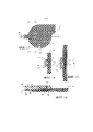
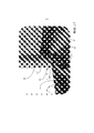
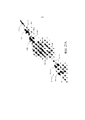
Можно использовать кровяные насосы различных типов, включая насос положительного смещения и роторный насос, причем насосы роторного типа являются предпочтительными. В одном из вариантов осуществления система роторного кровяного насоса содержит насос, который имеет корпус, который определяет впуск для того, чтобы принимать кровь, и выпуск для того, чтобы выбрасывать кровь. Корпус насоса разработан и имеет размеры для того, чтобы вмещать вращающийся импеллер, подвершенный на несущих. Корпус насоса может иметь первую несущую на впускной части корпуса и вторую несущую на выпускной части корпуса. Кровь входит во вращающийся импеллер и выходит из него, посредством чего импеллер увеличивает скорость крови на выходе. Эту увеличенную скорость извлекают или передают в виде увеличенного давления, поскольку кровь замедляется внутри диффузора насоса, который заканчивается выпуском насоса.Various types of blood pumps can be used, including a positive displacement pump and a rotary vane pump, with rotary vane pumps being preferred. In one embodiment, the rotary blood pump system comprises a pump that has a housing that defines an inlet for receiving blood and an outlet for ejecting blood. The pump casing is designed and sized to accommodate a rotating impeller that is suspended on carriers. The pump casing may have a first carrier at the inlet of the casing and a second carrier at the outlet of the casing. Blood enters and exits the rotating impeller, whereby the impeller increases the velocity of the blood outlet. This increased velocity is extracted or transmitted as increased pressure as the blood slows down inside the pump diffuser, which ends with the pump outlet.
В других вариантах осуществления можно использовать роторные кровяные насосы различных типов. Например, можно использовать осевой насос, радиально-осевой насос или, предпочтительно, центробежный кровяной насос. Кроме того, можно использовать различные несущие импеллера насоса, включая в качестве неограничивающих примеров магнитные несущие, гидродинамические несущие и, предпочтительно, поворотного (контактного) типа. Аналогичным образом, можно использовать диффузоры насоса различных типов, включая в качестве неограничивающих примеров коллектор диффузор или предпочтительно спиральный диффузор. In other embodiments, various types of rotary blood pumps can be used. For example, an axial-flow pump, a radial-axial pump, or preferably a centrifugal blood pump can be used. In addition, various pump impeller carriers can be used, including, but not limited to, magnetic carriers, hydrodynamic carriers, and preferably of the rotary (contact) type. Likewise, various types of pump diffusers can be used, including, but not limited to, a manifold diffuser or preferably a spiral diffuser.
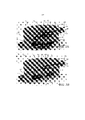
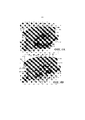
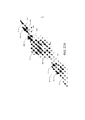
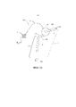
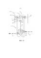
В одном из вариантов осуществления центробежный кровяной насос с поворотными опорами содержит корпус насоса, который определяет впуск насоса, который имеет диффузор входящего потока для того, чтобы принимать кровь и направлять кровь на импеллер, корпус насоса, который имеет верхнюю грань и верхнюю поворотную опору, которая идет от верхней части корпуса во впуск, и нижнюю грань и нижнюю поворотную опору, которая идет от нижней части корпуса во внутреннее пространство корпуса. Насос также содержит импеллер, подвешенный внутри корпуса, импеллер дополнительно имеет просвет несущей для того, чтобы принимать поворотный элемент импеллера. Поворотный элемент импеллера имеет первый конец для того, чтобы входить в зацепление с поворотной опорой впускной части (верхней), и второй конец для того, чтобы входить в зацепление с поворотной опорой выпускной части (нижней). В одном из вариантов осуществления концы поворотного элемента импеллера являются выпуклыми и по меньшей мере один конец каждой поворотной опоры является вогнутым. В другом варианте осуществления концы поворотного элемента импеллера являются вогнутыми, а поворотные опоры являются выпуклыми. Импеллер может содержать различные конструкции лопастей или лопаток, разработанные для того, чтобы контактировать с кровью и ускорять ее в улитку. Например, импеллер определяет множество лопаток на верхней поверхности импеллера, идущих радиально от центра импеллера к внешнему краю импеллера. Лопатки ускоряют кровь из центрального впуска импеллера к его периферическому выпуску. В другом варианте импеллер не содержит лопатки или лопасти, но содержит средство для того, чтобы перемещать или двигать кровь. Импеллер необязательно содержит по меньшей мере один просвет, вырез или канал для смыва, который идет параллельно центральной оси импеллера от нижней поверхности через импеллер к верхней поверхности. Просвет разрабатывают для того, чтобы предотвращать застой крови под импеллером и вокруг нижней поворотной опоры. In one embodiment, a pivot-bearing centrifugal blood pump includes a pump housing that defines a pump inlet that has an inlet diffuser to receive blood and direct the blood to an impeller, a pump housing that has an upper flange and an upper pivot bearing that goes from the upper part of the housing to the inlet, and the lower edge and the lower pivot support, which goes from the lower part of the housing to the interior of the housing. The pump also contains an impeller suspended inside the housing, the impeller additionally has a carrier lumen in order to receive the rotary element of the impeller. The impeller pivot member has a first end to engage with the inlet pivot bearing (top) and a second end to engage with the outlet pivot bearing (bottom). In one embodiment, the ends of the impeller pivot member are convex and at least one end of each pivot bearing is concave. In another embodiment, the ends of the impeller pivot member are concave and the pivot bearings are convex. The impeller may contain various blade or paddle designs designed to contact and accelerate blood into the cochlea. For example, an impeller defines a plurality of blades on the upper surface of the impeller extending radially from the center of the impeller to the outer edge of the impeller. The paddles accelerate blood from the central inlet of the impeller to its peripheral outlet. In another embodiment, the impeller does not contain a paddle or paddle, but contains means for moving or propelling blood. The impeller optionally includes at least one lumen, cutout or flush channel that runs parallel to the central axis of the impeller from the bottom surface through the impeller to the top surface. The lumen is designed to prevent blood stagnation under the impeller and around the lower pivot bearing.
Кровяной насос содержит двигатель, предпочтительно электрический, разработанный для того, чтобы приводить в действие импеллер. В одном из вариантов осуществления кровяной насос содержит приводной двигатель, который имеет по меньшей мере один магнит, механически прикрепленный к импеллеру и по меньшей мере одному якорю, механически прикрепленному к корпусу. Якорь индуцирует электродвижущую силу по меньшей мере на одном магните, прикрепленном к импеллеру. Двигатель насоса может представлять собой бесщеточный моментный двигатель постоянного тока (DC) с осевым пропуском с коммутацией противоэлектродвижущей силы (противо-ЭДС) без датчиков. В двигателе используют спеченный сплав неодимия железа бора (NdFeB) для магнитов в роторе и 3-фазную плоскую конфигурацию катушки типа «ипподром» в статоре. Двигатель имеет соотношение сторон как у диска, с очень малой длиной оси в сравнении с его диаметром.The blood pump comprises a motor, preferably an electric motor, designed to drive an impeller. In one embodiment, the blood pump comprises a drive motor that has at least one magnet mechanically attached to the impeller and at least one armature mechanically attached to the housing. The armature induces an electromotive force on at least one magnet attached to the impeller. The pump motor can be a brushless DC torque motor with an axial pass with back electromotive force (back EMF) commutation without sensors. The motor uses a sintered neodymium iron boron (NdFeB) alloy for the magnets in the rotor and a 3-phase flat track coil configuration in the stator. The motor has a disc-like aspect ratio with a very short axle length compared to its diameter.
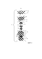
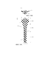
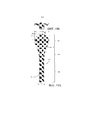
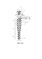
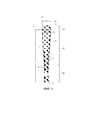
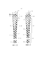
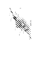
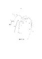
Система кровяного насоса имеет одну или несколько трубок, включая первую трубку (входящего потока), которая имеет две конца, первый конец, который соединяют по текучей среде с местоположением в сосудистой системе и который принимает кровь из этого местоположения, и второй конец, который соединяют по текучей среде с насосом. Трубка входящего потока доставляет кровь в насос. Система кровяного насоса имеет вторую трубку (выходящего потока), которая имеет два конца, первый конец, который соединяют по текучей среде с насосом и который принимает кровь от насоса, и второй конец, который соединяют по текучей среде с местоположением в сосудистой системе. Выходящий поток доставляет кровь в местоположение в сосудистой системе. The blood pump system has one or more tubes, including a first (inflow) tube that has two ends, a first end that is fluidly connected to a location in the vascular system and that receives blood from that location, and a second end that is connected through fluid medium with a pump. The inflow tube delivers blood to the pump. The blood pump system has a second (outflow) tube that has two ends, a first end that is in fluid communication with the pump and that receives blood from the pump, and a second end that is in fluid communication with a location in the vascular system. The outgoing stream delivers blood to a location in the vascular system.
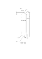
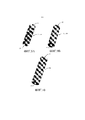
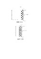
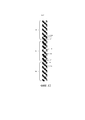
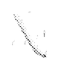
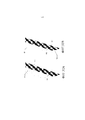
В различных вариантах осуществления трубки системы кровяного насоса имеют индивидуальную длину между 2 см и 110 см и общую длину между 4 см и 220 см, и могут быть усечены хирургом или другим врачом до желаемой длины, в том числе, во время имплантации насосной системы. Каждая трубка имеет внутренний диаметр между 2 мм и 10 мм и предпочтительно между 4 мм и 6 мм. Трубки можно формировать по меньшей мере отчасти из полиуретана (такого как Pellethane® или Carbothane®), поливинилхлорида, полиэтилена, силиконового эластомера, политетрафторэтилена (ПТФЭ), пористого политетрафторэтилена (пПТФЭ), полиэтилентерефталата (ПЭТ, например, дакрона) и их сочетаний. Трубки дополнительно могут содержать эластический резервуар.In various embodiments, the tubes of the blood pump system have an individual length between 2 cm and 110 cm and an overall length between 4 cm and 220 cm, and can be truncated by a surgeon or other physician to the desired length, including during implantation of the pumping system. Each tube has an inner diameter between 2 mm and 10 mm, and preferably between 4 mm and 6 mm. The tubes may be formed at least partly of polyurethane (such as Pellethane ® or Carbothane ®), polyvinyl chloride, polyethylene, silicone elastomer, polytetrafluoroethylene (PTFE), expanded polytetrafluoroethylene (ePTFE), polyethylene terephthalate (PET, e.g., dacron), and combinations thereof. The tubes can additionally contain an elastic reservoir.
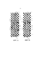
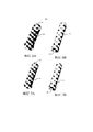
Все или части трубок можно упрочнять сплетенным или спирально завитым материалом с памятью формы, таким как нитинол, или другим саморасправляющимся или радиально расширяющимся материалом. Трубки могут иметь скошенные концы, которые соединяют по текучей среде с сосудистой системой. Концы могут быть скошенным под углом между 10 градусами и 80 градусами. Одна или несколько трубок могут иметь множество отверстий или окошек в стенках дистальных концов, когда выполняют с возможностью размещения внутри просвета кровеносного сосуда или другом внутрисосудистом местоположении. Трубки можно прикреплять к насосу с использованием радиально-сжимаемых соединителей.All or parts of the tubes can be reinforced with a woven or spirally wound shape memory material such as Nitinol or other self-expanding or radially expanding material. The tubes may have beveled ends that are in fluid communication with the vascular system. The ends can be beveled at an angle between 10 degrees and 80 degrees. One or more tubes may have a plurality of holes or windows in the walls of the distal ends when configured to be placed within the lumen of a blood vessel or other intravascular location. Tubing can be attached to the pump using radially compressible connectors.
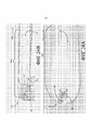
В одном из вариантов осуществления система кровяного насоса содержит кровяной насос и систему управления для того, чтобы осуществлять мониторинг системы кровяного насоса и модифицировать работу кровяного насоса для того, чтобы поддерживать увеличенное среднее напряжение сдвига у стенки внутри артерии или вены, соединенной по текучей среде с кровяным насосом. Система управления дополнительно выполнена с возможностью поддерживать среднее напряжение сдвига у стенки внутри вены в диапазоне от 0,76 до 23 Па, или предпочтительно в диапазоне от 2,5 до 10 Па. В другом варианте осуществления система управления осуществляет мониторинг и поддерживает увеличенную среднюю скорость крови внутри артерии или вены, соединенной по текучей среде с кровяным насосом. В этом варианте осуществления система управления выполнена с возможностью поддерживать среднюю скорость крови внутри артерии или вены в диапазоне от 10 см/с до 120 см/с, или предпочтительно в диапазоне от 25 см/с до 100 см/с. В любом варианте осуществления система кровяного насоса выполнена с возможностью поддерживать увеличенное среднее напряжение сдвига у стенки или увеличенную среднюю скорость крови в течение по меньшей мере 1 суток, 7 суток, 14 суток, 28 суток, 42 суток, 56 суток, 84 суток или 112 суток. In one embodiment, the blood pump system comprises a blood pump and a control system for monitoring the blood pump system and modifying the operation of the blood pump to maintain an increased average shear stress at a wall within an artery or vein fluidly connected to the blood pump. The control system is further configured to maintain an average shear stress at the wall inside the vein in the range of 0.76 to 23 Pa, or preferably in the range of 2.5 to 10 Pa. In another embodiment, the control system monitors and maintains an increased mean blood velocity within an artery or vein in fluid communication with the blood pump. In this embodiment, the control system is configured to maintain an average blood velocity within an artery or vein in the range of 10 cm / s to 120 cm / s, or preferably in the range of 25 cm / s to 100 cm / s. In any embodiment, the blood pump system is configured to maintain an increased mean wall shear stress or an increased mean blood velocity for at least 1 day, 7 days, 14 days, 28 days, 42 days, 56 days, 84 days, or 112 days. ...
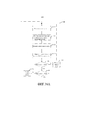
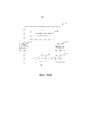
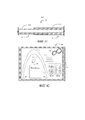
Система кровяного насоса имеет систему управления для того, чтобы достигать и поддерживать желаемую скорость потока, которая необязательно может содержать управляющее устройство для приема информации и управления работой насоса системы перекачивания крови. Как минимум, систему управления можно приводить в действие вручную для того, чтобы регулировать скорость двигателя. С другой стороны, можно использовать автоматическую (т.е. «умную») систему управления. Необязательно, система управления содержит датчики, которые можно располагать в насосе, трубках или в сосудистой системе пациента. Управляющее устройство может измерять скорость вращения двигателя, основываясь на прохождении через ноль и форме волны противо-ЭДС. Это прохождение через ноль указывает на изменение магнитного полюса ротора на противоположный. Скоростью двигателя управляют посредством широтно-импульсной модуляции (ШИМ) входного напряжения, а крутящим моментом управляют посредством ШИМ входного тока. Управляющее устройство также осуществляет мониторинг других переменных состояния двигателя насоса, таких как ток и напряжение, по которым можно оценивать как скорость потока через систему перекачивания крови, так и напряжение сдвига у стенки в периферическом кровяном сосуде, и управлять ими. Управляющее устройство предпочтительно содержит память, процессор для управления скоростью двигателя насоса, анализа информации, поступающей от электроники привода двигателя и необязательных датчиков, и исполнения инструкций, закодированных в машиночитаемой среде. Система кровяного насоса содержит кабель для электрического соединения управляющего устройства с насосом и необязательными датчиками. Система кровяного насоса также содержит источник мощности, который в различных вариантах осуществления можно интегрировать в управляющее устройство. В различных вариантах осуществления источник мощности для системы кровяного насоса может быть переносным (например, перезаряжаемая батарея или топливная ячейка) или стационарным (например, базовый блок питания, соединенный с сетью переменного тока).The blood pump system has a control system for achieving and maintaining a desired flow rate, which may optionally include a control device for receiving information and controlling the operation of the pump of the blood pumping system. At a minimum, the control system can be manually operated to regulate the engine speed. On the other hand, an automatic (ie "smart") control system can be used. Optionally, the control system contains sensors that can be located in the pump, tubing, or in the patient's vascular system. The control device can measure the engine speed based on the zero crossing and back EMF waveform. This zero crossing indicates a reversal of the rotor magnetic pole. Motor speed is controlled by pulse width modulation (PWM) of the input voltage, and torque is controlled by PWM of the input current. The controller also monitors and controls other pump motor status variables such as current and voltage, from which both the flow rate through the blood pumping system and the shear stress at the wall in the peripheral blood vessel can be estimated. The control device preferably comprises a memory, a processor for controlling the speed of the pump motor, analyzing information from the motor drive electronics and optional sensors, and executing instructions encoded in a machine-readable medium. The blood pump system contains a cable for the electrical connection of the control device to the pump and optional sensors. The blood pump system also includes a power source that, in various embodiments, can be integrated into a control device. In various embodiments, the power source for the blood pump system can be portable (eg, a rechargeable battery or fuel cell) or stationary (eg, a basic power supply connected to an AC power source).
Система управления может получать информацию из различных источников. Электроника привода двигателя внутри управляющего устройства может измерять по меньшей мере одно из скорости двигателя, входной мощности или тока, необходимого для работы насоса. В других вариантах осуществления система управления содержит датчики в кровяном насосе или трубках, которые измеряют по меньшей мере одно из скорости крови, скорости потока крови, сопротивления потоку крови в периферическом кровяном сосуде, кровяного давления, пульсационного индекса и их сочетаний. В других вариантах осуществления система управления содержит датчики в сосудистой системе пациента, которые измеряют по меньшей мере одно из скорости крови, скорости потока крови, кровяного давления, пульсационного индекса, диаметра сосуда и их сочетаний. The control system can receive information from various sources. The motor drive electronics within the control device may measure at least one of the motor speed, input power, or current required to operate the pump. In other embodiments, the control system comprises sensors in the blood pump or tubes that measure at least one of blood velocity, blood flow rate, resistance to blood flow in a peripheral blood vessel, blood pressure, pulsation index, and combinations thereof. In other embodiments, the control system comprises sensors in the patient's vascular system that measure at least one of blood velocity, blood flow rate, blood pressure, pulsation index, vessel diameter, and combinations thereof.
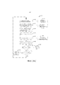
В различных вариантах осуществления система управления может оценивать и поддерживать желаемый и повышенный уровень напряжения сдвига у стенки в целевом сосуде или отдающей артерии или вене, используя информацию от управляющего устройства и/или датчиков, такую как скорость двигателя, входная мощность двигателя, скорость потока насоса, напор насоса, давление около сочленения трубки выходящего потока и целевого сосуда, падение давления на протяжении кровеносного сосуда и их сочетания. В целях этой заявки «целевой сосуд», «целевой кровеносный сосуд», «целевая вена» или «целевая артерия» относится к конкретному сегменту артерии или вены, который предназначен для достижения постоянно увеличенного наружного диаметра и диаметра просвета, когда сборочный узел насос-трубка имплантируют, конфигурируют и приводят в действие таким образом, чтобы достичь постоянного увеличения наружного диаметра и диаметра просвета. In various embodiments, the control system can estimate and maintain a desired and increased level of shear stress at the wall in the target vessel or emitting artery or vein using information from the control device and / or sensors, such as motor speed, motor input power, pump flow rate, pump head, pressure near the junction of the outflow tube and target vessel, pressure drop across the blood vessel, and combinations thereof. For the purposes of this application, “target vessel”, “target blood vessel”, “target vein” or “target artery” refers to a particular segment of an artery or vein that is designed to achieve a continuously increased outer and lumenal diameter when the pump-tube assembly implanted, configured and operated in such a way as to achieve a constant increase in the outer diameter and the diameter of the lumen.
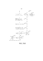
Различные способы системы управления можно использовать для того, чтобы автоматически управлять работой системы кровяного насоса. В одном из вариантов осуществления способ определения напряжения сдвига у стенки и управления им в кровеносном сосуде включает стадии измерения вязкости крови, измерения скорости потока крови в системе кровяного насоса или кровеносном сосуде и измерение радиуса кровеносного сосуда. Стадии также включают определение напряжения сдвига у стенки в кровеносном сосуде по измеряемой вязкости крови, измеряемой скорости потока и радиусу кровеносного сосуда, сравнения определяемого напряжения сдвига у стенки с заданным эталонным значением и корректировки скорости кровяного насоса, когда определяемое напряжение сдвига у стенки не приближено к заданному эталонному значению. Стадии повторяют до тех пор, пока определяемое напряжение сдвига у стенки не приблизится к заданному эталонному значению.Various methods of the control system can be used to automatically control the operation of the blood pump system. In one embodiment, a method for detecting and controlling shear stress at a wall in a blood vessel includes the steps of measuring blood viscosity, measuring blood flow rate in a blood pump system or blood vessel, and measuring a radius of the blood vessel. The steps also include determining the wall shear stress in the blood vessel from the measured blood viscosity, the measured flow rate and radius of the blood vessel, comparing the measured wall shear stress with a predetermined reference value, and adjusting the blood pump speed when the determined wall shear stress is not close to the target. reference value. The steps are repeated until the determined wall shear stress approaches the predetermined reference value.
В другом варианте осуществления способ вычисления и управления напряжением сдвига у стенки в кровеносном сосуде включает стадии оценки вязкости крови, измерения скорости потока крови в системе кровяного насоса или кровеносном сосуде и измерения радиуса кровеносного сосуда. Стадии также включают определение напряжения сдвига у стенки по оцениваемой вязкости крови, измеряемой скорости потока крови и радиусу кровеносного сосуда, сравнение определяемого напряжения сдвига у стенки с заданным эталонным значением и корректировку скорости кровяного насоса, когда определяемое напряжение сдвига у стенки не приближено к заданному эталонному значению. Стадии повторяют до тех пор, пока определяемое напряжение сдвига у стенки не приблизится к заданному эталонному значению.In another embodiment, a method for calculating and controlling shear stress at a wall in a blood vessel includes the steps of evaluating blood viscosity, measuring the blood flow rate in a blood pump system or blood vessel, and measuring the radius of the blood vessel. The steps also include determining the wall shear stress from the estimated blood viscosity, the measured blood flow rate and the radius of the blood vessel, comparing the detected wall shear stress with a predetermined reference value, and adjusting the blood pump speed when the determined wall shear stress is not close to the predetermined reference value. ... The steps are repeated until the determined wall shear stress approaches the predetermined reference value.
В одном из вариантов осуществления способ оценки напряжения сдвига у стенки в кровеносном сосуде и управления им включает стадии оценки вязкости крови, измерения по меньшей мере одной переменной состояния двигателя системы кровяного насоса, выбранной из напряжения, тока или скорости насоса, и оценки скорости потока крови в системе кровяного насоса. Стадии также включают измерение давления в кровеносном сосуде, определение сопротивления сосуда у кровеносного сосуда по оцениваемой скорости потока крови и измеряемому давлению в кровеносном сосуде, оценку радиуса кровеносного сосуда. Стадии дополнительно включают определение напряжения сдвига у стенки по оцениваемой вязкости крови, оцениваемой скорости потока крови и радиусу кровеносного сосуда, по сравнению с определяемым напряжением сдвига у стенки с заданным эталонным значением, и корректировку скорости насоса, когда определяемое напряжение сдвига у стенки не приближено к заданному эталонному значению. Стадии повторяют до тех пор, пока определяемое напряжение сдвига у стенки не приблизится к заданному эталонному значению.In one embodiment, a method for assessing and controlling shear stress at a wall in a blood vessel includes the steps of assessing blood viscosity, measuring at least one motor state variable of the blood pump system selected from voltage, current, or pump speed, and assessing the blood flow rate in the blood pump system. The steps also include measuring the pressure in the blood vessel, determining the resistance of the vessel at the blood vessel from the estimated blood flow rate and the measured pressure in the blood vessel, and estimating the radius of the blood vessel. The steps additionally include determining the wall shear stress from the estimated blood viscosity, the estimated blood flow rate and the radius of the blood vessel versus the determined wall shear stress with a predetermined reference value, and adjusting the pump speed when the determined wall shear stress is not close to the predetermined reference value. The steps are repeated until the determined wall shear stress approaches the predetermined reference value.
В другом варианте осуществления способ оценки напряжения сдвига у стенки в кровеносном сосуде и управления им с использованием системы кровяного насоса включает стадии оценки вязкости крови, измерения по меньшей мере одной переменной состояния двигателя системы кровяного насоса, выбранной из напряжения, тока или скорости насоса, и оценки скорости потока крови и напора в системе кровяного насоса. Стадии также включают вычисление сопротивления сосуда у кровеносного сосуда по оцениваемой скорости потока крови и оцениваемому напору, оценку радиуса кровеносного сосуда и определение напряжения сдвига у стенки по оцениваемой вязкости крови, оцениваемой скорости потока крови и радиусу кровеносного сосуда. Стадии дополнительно включают сравнение определяемого напряжения сдвига у стенки с заданным эталонным значением и корректировку скорости насоса, когда определяемое напряжение сдвига у стенки не приближено к заданному эталонному значению. Стадии повторяют до тех пор, пока определяемое напряжение сдвига у стенки не приблизится к заданному эталонному значению.In another embodiment, a method for assessing and controlling shear stress at a wall in a blood vessel using a blood pump system includes the steps of assessing blood viscosity, measuring at least one motor state variable of the blood pump system selected from voltage, current, or pump speed, and evaluating blood flow rate and pressure in the blood pump system. The steps also include calculating the vessel resistance at the blood vessel from the estimated blood flow rate and the estimated head, estimating the radius of the blood vessel, and determining the shear stress at the wall from the estimated blood viscosity, the estimated blood flow rate, and the radius of the blood vessel. The steps further include comparing the detected wall shear stress with a predetermined reference value and adjusting the pump speed when the detected wall shear stress is not close to the predetermined reference value. The steps are repeated until the determined wall shear stress approaches the predetermined reference value.
В одном из вариантов осуществления способ оценки напряжения сдвига у стенки в кровеносном сосуде и управления им с использованием системы кровяного насоса включает стадии оценки по меньшей мере одного элемента, выбранного из группы, состоящей из вязкости крови, скорости потока крови, напора в системе кровяного насоса и радиуса кровеносного сосуда, измерения по меньшей мере одной переменной состояния двигателя системы кровяного насоса выбранной из группы, состоящей из напряжения, тока и скорости насоса, и определения напряжения сдвига у стенки в кровеносном сосуде. Стадии также включают сравнение определяемого напряжения сдвига у стенки с заданным эталонным значением и корректировку скорости насоса, когда определяемое напряжение сдвига у стенки не приближено к заданному эталонному значению. Стадии повторяют до тех пор, пока определяемое напряжение сдвига у стенки не приблизится к заданному эталонному значению.In one embodiment, a method for evaluating and controlling shear stress at a wall in a blood vessel using a blood pump system comprises the steps of evaluating at least one element selected from the group consisting of blood viscosity, blood flow rate, head in a blood pump system, and the radius of the blood vessel, measuring at least one motor state variable of the blood pump system selected from the group consisting of voltage, current, and pump speed, and determining the shear stress at the wall in the blood vessel. The steps also include comparing the detected wall shear stress with a predetermined reference value and adjusting the pump speed when the detected wall shear stress is not close to the predetermined reference value. The steps are repeated until the determined wall shear stress approaches the predetermined reference value.
В еще одном другом варианте осуществления, бездатчиковый способ, предназначенный для того, чтобы избегать коллапса кровеносного сосуда, соединенного по текучей среде с системой кровяного насоса, при обнаружении приближения коллапса на впуске системы кровяного насоса, включает стадии измерения тока двигателя кровяного насоса и непрерывного определения представления спектрального анализа тока двигателя кровяного насоса в форме ряда Фурье. Стадии также включают предоставление индикации обнаружения, когда амплитуда второго гармонического члена ряда Фурье превышает эталонное значение, и снижение скорости насоса, когда амплитуда второго гармонического члена ряда Фурье превышает эталонное значение. Стадии повторяют до тех пор, пока амплитуда второго гармонического члена не упадет ниже эталонного значения.In yet another embodiment, a sensorless method for avoiding collapse of a blood vessel in fluid communication with a blood pump system upon detecting an impending collapse of an inlet of the blood pump system includes the steps of measuring the blood pump motor current and continuously determining the view spectral analysis of the blood pump motor current in the form of a Fourier series. The steps also include providing a detection indication when the amplitude of the second harmonic term of the Fourier series exceeds the reference value, and decreasing the pump speed when the amplitude of the second harmonic term of the Fourier series exceeds the reference value. The steps are repeated until the amplitude of the second harmonic term falls below the reference value.
В различных других вариантах осуществления системы и способы, описанные в настоящем документе, могут быть закодированы в машиночитаемых средах, которые можно исполнять с использованием каких-либо эталонных значений или заданных стандартов, используемых системами и способами, можно хранить в базе данных или другой подходящей запоминающей среде. In various other embodiments, the systems and methods described herein may be encoded in computer readable media that may be executed using any reference values or predetermined standards used by systems and methods, may be stored in a database or other suitable storage medium. ...
КРАТКОЕ ОПИСАНИЕ РИСУНКОВBRIEF DESCRIPTION OF THE FIGURES
На фиг. 1 представлен изометрический вид насоса. FIG. 1 is an isometric view of the pump.
На фиг. 2 представлен разборный изометрический вид насоса, где показаны его компоненты, содержащиеся в теле, идентифицированном на фиг. 1. FIG. 2 is a disassembled isometric view of the pump showing the components contained in the body identified in FIG. 1.
На фиг. 3A и 3B представлен вертикальный вид частичного и полного поперечного сечения насоса, соответственно, выполненного по линии сечения 3-3 на фиг. 1.FIG. 3A and 3B are partial and full cross-sectional elevational views of the pump, respectively, taken along section line 3-3 in FIG. 1.
На фиг. 4A и 4B представлен вертикальный вид частичного и полного поперечного разреза насоса, соответственно, выполненного по линии сечения 4-4 на фиг. 1. FIG. 4A and 4B are partial and full cross-sectional elevational views of the pump, respectively, taken along section line 4-4 in FIG. 1.
На фиг. 5A-B представлены увеличенные виды области оси поворота area с фиг. 3B и 4B.FIG. 5A-B are enlarged views of the pivot axis area of FIG. 3B and 4B.
На фиг. 6A-B представлены изометрические виды сверху и снизу, соответственно, поворотного элемента импеллера.FIG. 6A-B are top and bottom isometric views, respectively, of the pivot element of the impeller.
На фиг. 7A-B представлены изометрические виды сверху и снизу, соответственно, поворотного элемента импеллера.FIG. 7A-B are top and bottom isometric views, respectively, of the pivot element of the impeller.
На фиг. 8A-B представлены вертикальные виды сбоку вариантов осуществления поворотного элемента импеллера.FIG. 8A-B are side elevational views of embodiments of an impeller pivot member.
На фиг. 9A-B соответствующим образом представлены виды с противоположных торцов репрезентативный несущий штырь, используемый на любой конце оси импеллера для того, чтобы поддерживать и делать возможным вращение поворотного элемента импеллера. FIG. 9A-B respectively show opposite end views of a representative support pin used at either end of the impeller shaft to support and allow rotation of the impeller pivot member.
На фиг. 10 представлен вид варианта осуществления верхнего несущего штыря.FIG. 10 is a view of an embodiment of an upper carrier pin.
На фиг. 11A-B представлены вертикальные виды сбоку вариантов осуществления репрезентативного несущего штыря.FIG. 11A-B are side elevational views of embodiments of a representative carrier pin.
На фиг. 12 представлено продольно сечение репрезентативного сборочного узла несущего штыря.FIG. 12 is a longitudinal sectional view of a representative carrier pin assembly.
На фиг. 13 представлен вид сверху впускной головки и кожуха импеллера.FIG. 13 is a top view of the intake head and impeller housing.
На фиг. 14-16 соответствующим образом представлены вертикальные виды поперечного сечения, выполненного по линиям сечения 14-14, 15-15 и 16-16 на фиг. 13.FIG. 14-16 are correspondingly vertical cross-sectional views taken along section lines 14-14, 15-15, and 16-16 in FIGS. 13.
На фиг. 17 представлено изометрическое частичное поперечное сечение впускного отверстия камеры импеллера. FIG. 17 is an isometric partial cross-sectional view of the impeller chamber inlet.
На фиг. 18A и 18B соответствующим образом представлены вид сверху части впускной головки, которая определяет впускной канал, и ее торцевой вертикальный вид.FIG. 18A and 18B respectively show a top view of a portion of an intake head that defines an intake port and an end vertical view thereof.
На фиг. 19A и 19B представлены те же соответствующие виды, как на фиг. 18A и 18B, но для другого варианта осуществления. FIG. 19A and 19B show the same corresponding views as in FIG. 18A and 18B, but for a different embodiment.
На фиг. 20A и 20B представлены те же соответствующие виды, как на фиг. 18A и 18B, но для другого варианта осуществления.FIG. 20A and 20B are the same corresponding views as in FIG. 18A and 18B, but for a different embodiment.
На фиг. 21-23 представлены те же виды, как на фиг. 18A, но для трех других вариантов осуществления.FIG. 21-23 show the same views as in FIG. 18A, but for three other embodiments.
На фиг. 24A и 24B представлены соответствующим образом вид сверху и вертикальный вид сбоку другого варианта осуществления впускной головки и впускного канала, похожие на представленное на фиг. 21, но дополнительно содержащие дугообразную клиновидную часть. FIG. 24A and 24B are top and side elevational views, respectively, of another embodiment of the inlet head and inlet, similar to that of FIG. 21, but additionally containing an arcuate wedge-shaped portion.
На фиг. 25 представлен изометрический вид насоса с удаленным верхним кожухом импеллера, чтобы показать импеллер, который занимает камеру импеллера. FIG. 25 is an isometric view of the pump with the upper impeller casing removed to show the impeller that occupies the impeller chamber.
На фиг. 26 представлен вид в перспективе системы кровяного насоса согласно одному из вариантов осуществления.FIG. 26 is a perspective view of a blood pump system in accordance with one embodiment.
На фиг. 27A-27D представлены виды в перспективе соединения между насосом и трубками согласно одному из вариантов осуществления.FIG. 27A-27D are perspective views of a connection between a pump and tubing in accordance with one embodiment.
На фиг. 28A и 28B представлены виды в перспективе соединения между насосом и трубками согласно одному из вариантов осуществления.FIG. 28A and 28B are perspective views of a connection between a pump and tubing in accordance with one embodiment.
На фиг. 29A и 29B представлены виды в перспективе соединения между насосом и трубками, которое содержит боковой порт согласно одному из вариантов осуществления.FIG. 29A and 29B are perspective views of a pump-to-tubing connection that includes a side port, in accordance with one embodiment.
На фиг. 30A и 30B представлены виды в перспективе соединения между насосом и трубками, которое содержит перегородку согласно одному из вариантов осуществления.FIG. 30A and 30B are perspective views of a connection between a pump and pipes that includes a baffle, in accordance with one embodiment.
На фиг. 31 представлен вид дистальной части трубки выходящего потока согласно одному из вариантов осуществления.FIG. 31 is a view of a distal portion of an outflow tube in accordance with one embodiment.
На фиг. 32A и 32B представлены виды внутрисосудистой части трубки входящего потока согласно одному из вариантов осуществления.FIG. 32A and 32B are views of the intravascular portion of an inflow tube in accordance with one embodiment.
На фиг. 33 представлен схематический вид насосной системы согласно одному из вариантов осуществления. FIG. 33 is a schematic view of a pumping system in accordance with one embodiment.
На фиг. 34 представлен схематический вид насосной системы согласно другому варианту осуществления. FIG. 34 is a schematic view of a pumping system according to another embodiment.
На фиг. 35 представлен схематический вид системы управления согласно одному из вариантов осуществления.FIG. 35 is a schematic view of a control system in accordance with one embodiment.
На фиг. 36A-36D представлены блок-схемы способов системы управления согласно различным вариантам осуществления.FIG. 36A-36D are flow charts of control system methods in accordance with various embodiments.
На фиг. 36E представлен график для давления в анастомозе и скорости потока крови для модели насосной системы in vitro согласно одному из вариантов осуществления.FIG. 36E is a graph for anastomotic pressure and blood flow rate for an in vitro pumping system model according to one embodiment.
На фиг. 36F-36H представлены блок-схемы способов системы управления согласно различным вариантам осуществления.FIG. 36F-36H are flow charts of control system methods in accordance with various embodiments.
На фиг. 37 представлен схематический вид насосной системы, как применяют в системе кровообращения пациента, согласно одному из вариантов осуществления.FIG. 37 is a schematic view of a pumping system as used in a patient's circulatory system, in accordance with one embodiment.
На фиг. 38 представлен схематический вид насосной системы, как применяют в системе кровообращения пациента, согласно второму варианту осуществления. FIG. 38 is a schematic view of a pumping system as applied to a patient's circulatory system according to a second embodiment.
На фиг. 39 представлен схематический вид системы без насоса, как применяют в системе кровообращения пациента согласно третьему варианту осуществления. FIG. 39 is a schematic view of a system without a pump as applied to a patient's circulatory system according to a third embodiment.
На фиг. 40 представлен схематический вид насосной системы, как применяют в системе кровообращения пациента, согласно четвертому варианту осуществления.FIG. 40 is a schematic view of a pumping system as applied to a patient's circulatory system according to a fourth embodiment.
На фиг. 41 представлено продольное сечение сочленения между проксимальным сегментом и дистальным сегментом.FIG. 41 is a longitudinal sectional view of the articulation between the proximal segment and the distal segment.
На фиг. 42 представлен вид сверху медицинского набора.FIG. 42 is a top view of a medical kit.
На фиг. 43 представлено схематическое изображение насосной системы, которой управляют в соответствии с давлением выходящего потока.FIG. 43 is a schematic diagram of a pumping system that is controlled in accordance with the outlet flow pressure.
ПОДРОБНОЕ ОПИСАНИЕ ИЗОБРЕТЕНИЯDETAILED DESCRIPTION OF THE INVENTION
Системы и компоненты настоящей заявки относятся к системе кровяного насоса. Более конкретно, в различных вариантах осуществления настоящая заявка относится к кровяному насосу, который разработан и имеет размеры для того, чтобы выбрасывать кровь в целевой сосуд или забирать кровь из целевого сосуда таким образом и в течение такого периода времени, что происходит постоянное увеличение диаметра целевого сосуда (вены или артерии). Еще более конкретно, настоящая заявка относится к системе роторного кровяного насоса, выполненного с возможностью постоянно увеличивать среднюю и/или пиковую скорость крови и среднее и/или пиковое напряжение сдвига у стенки в выбранных сегментах вен или артерий в течение периода времени, достаточного для того, чтобы постоянно увеличивать наружный диаметр и диаметр просвета выбранных сегментов вен или артерий. Термин «постоянное увеличение» или «постоянная дилятация», когда используют для того, чтобы описывать дилятацию или увеличению наружного диаметра и диаметра просвета артерии или вены, используют в настоящем документе для того, чтобы обозначать, что даже если насос выключают, увеличение наружного диаметра или диаметра просвета сосуда все еще можно демонстрировать, по сравнению с наружным диаметром или диаметром просвета сосуда перед периодом перекачивания крови. То есть, наружный диаметр или диаметр просвета сосуда стал больше, независимо от давления, создаваемого насосом. Следовательно, систему кровяного насоса можно использовать у определенных пациентов, включая пациентов с CKD, которые нуждаются в месте сосудистого доступа для гемодиализа. Система кровяного насоса может содержать роторный кровяной насос, одну или несколько несущих кровь трубок, систему управления и источник мощности. Система кровяного насоса забирает кровь из одного местоположения в сосудистой системе и выбрасывает кровь в другое местоположение в сосудистой системе. Во время работы, такая система кровяного насоса может постоянно увеличивать среднюю и/или пиковую скорость крови и среднее и/или пиковое НСС в целевом кровеносном сосуде до уровня и в течение периода времени, достаточных для того, чтобы постоянно увеличивать наружный диаметр и диаметр просвета целевого кровеносного сосуда. Система функционирует в конфигурациях, где кровь забирают из целевого кровеносного сосуда или в конфигурациях, где кровь выбрасывают в целевой кровеносный сосуд. Кроме того, систему можно использовать одновременно для того, чтобы увеличивать размер отдающих и принимающих сосудов.The systems and components of this application are directed to a blood pump system. More specifically, in various embodiments, the implementation of the present application relates to a blood pump that is designed and sized to eject blood into a target vessel or draw blood from a target vessel in such a way and for such a period of time that there is a continuous increase in the diameter of the target vessel. (veins or arteries). Even more specifically, the present application relates to a rotary blood pump system configured to continuously increase mean and / or peak blood velocity and mean and / or peak wall shear stress in selected segments of veins or arteries over a period of time sufficient to to continuously increase the outer diameter and the diameter of the lumen of the selected segments of veins or arteries. The term "permanent increase" or "permanent dilation", when used to describe dilatation or increase in the outer diameter and diameter of the lumen of an artery or vein, is used herein to mean that even if the pump is turned off, an increase in the outer diameter or the diameter of the vessel lumen can still be demonstrated in comparison to the outer diameter or the diameter of the vessel lumen before the period of pumping blood. That is, the outer diameter or the diameter of the lumen of the vessel has become larger, regardless of the pressure generated by the pump. Consequently, the blood pump system can be used in certain patients, including patients with CKD who require a vascular access site for hemodialysis. The blood pump system may include a rotary blood pump, one or more blood-carrying tubes, a control system, and a power source. The blood pump system draws blood from one location in the vascular system and discharges blood to another location in the vascular system. During operation, such a blood pump system can continuously increase the mean and / or peak blood velocity and the mean and / or peak HCC in the target blood vessel to a level and for a period of time sufficient to continuously increase the outer and lumen diameters of the target blood vessel. blood vessel. The system operates in configurations where blood is drawn from a target blood vessel or in configurations where blood is discharged into a target blood vessel. In addition, the system can be used simultaneously to increase the size of the giving and receiving vessels.
Необязательные несущие кровь трубки могут содержать трубки входящего потока для того, чтобы нести кровь из местоположения в сосудистой системе (такого как отдающая вена, отдающая артерия или правое предсердие) к кровяному насосу, и трубки выходящего потока для того, чтобы нести кровь от кровяного насоса к местоположению в сосудистой системе (такому как принимающая периферическая вена или артерия или принимающее местоположение, такое как правое предсердие). Система кровяного насоса также содержит систему управления. Предпочтительную систему управления разрабатывают для того, чтобы собирать информацию о рабочих параметрах и эффективности системы кровяного насоса и изменениях в сосудистой системе, таких как изменения диаметра отдающей артерии, отдающей вены, принимающей артерии или принимающей вены пациента. Систему кровяного насоса в первую очередь выполняют с возможностью перекачивать такое достаточное количество крови, что желаемое среднее и/или пиковое напряжение сдвига у стенки (НСС) достигают в сегменте кровеносного сосуда («целевой кровеносный сосуд» или «целевой сосуд»), и в течение такого достаточного периода времени, что перманентно или постоянно увеличивают наружный диаметр и диаметр просвета сегмента кровеносного сосуда. Среднее НСС можно вычислять с использованием измеряемого, оцениваемого или предполагаемого диаметра сосуда и измеряемой, оцениваемой или предполагаемой средней скорости потока крови через систему кровяного насоса. Optional blood-carrying tubes may include inflow tubes to carry blood from a location in the vascular system (such as the emitting vein, the emitting artery, or the right atrium) to the blood pump, and outflow tubes to carry blood from the blood pump to a location in the vascular system (such as a receiving peripheral vein or artery, or a receiving location such as the right atrium). The blood pump system also contains a control system. A preferred control system is designed to collect information about the operating parameters and efficiency of the blood pump system and changes in the vascular system, such as changes in the diameter of the outgoing artery, outgoing vein, receiving artery, or receiving vein of the patient. The blood pump system is primarily configured to pump a sufficient amount of blood such that the desired mean and / or peak wall shear stress (HSS) is reached in a segment of the blood vessel (“target blood vessel” or “target vessel”), and for such a sufficient period of time that the outer diameter and the diameter of the lumen of the blood vessel segment are permanently or permanently increased. The average HLR can be calculated using a measured, estimated, or inferred vessel diameter and a measured, estimated, or inferred average blood flow rate through the blood pump system.
Диаметр кровеносных сосудов можно определять посредством измерения диаметра свободного пространства в центре кровеносного сосуда. В целях этой заявки это измерение обозначают как «диаметр просвета». Диаметр кровеносных сосудов можно определять посредством измерения диаметра таким образом, который включает свободное пространство в центре кровеносного сосуда и стенку кровеносного сосуда. В целях этой заявки это измерение обозначают как «наружный диаметр». Изобретение относится к синхронному и постоянному увеличению наружного диаметра и диаметра просвета периферической вены посредством перемещения крови (предпочтительно с низким пульсовым давлением) в периферическую принимающую вену, тем самым увеличивая скорость крови в периферической принимающей вене и увеличивая НСС на эндотелии периферической принимающей вены. Описаны системы и способы, где скорость крови в периферической принимающей венке и НСС на эндотелии периферической принимающей вены увеличивают посредством использования насоса. Также описаны системы и способы, которые забирают или «всасывают» кровь так, что скорость крови и НСС увеличивают в отдающем сосуде, или артерии или вене. Предпочтительно, насос активно выбрасывает кровь в периферическую принимающую вену, где перекачиваемая кровь имеет сниженное пульсовое давление, например, когда пульсовое давление ниже чем у крови в периферической артерии.The diameter of the blood vessels can be determined by measuring the diameter of the free space in the center of the blood vessel. For the purposes of this application, this measurement is referred to as "lumen diameter". The diameter of the blood vessels can be determined by measuring the diameter in a manner that includes the free space at the center of the blood vessel and the wall of the blood vessel. For the purposes of this application, this measurement is referred to as "outer diameter". The invention relates to a synchronous and continuous increase in the outer diameter and the diameter of the lumen of the peripheral vein by moving blood (preferably with a low pulse pressure) into the peripheral receiving vein, thereby increasing the blood velocity in the peripheral receiving vein and increasing the HCC on the endothelium of the peripheral receiving vein. Described are systems and methods where the velocity of blood in the peripheral receiving vein and HCC on the endothelium of the peripheral receiving vein is increased by using a pump. Also described are systems and methods that draw or "suck" blood such that the velocity of blood and HCC is increased in the giving vessel, or artery or vein. Preferably, the pump actively ejects blood into a peripheral receiving vein where the pumped blood has a reduced pulse pressure, for example, when the pulse pressure is lower than that of blood in the peripheral artery.
Чтобы начать подробное обсуждение кровяного насоса 25 системы 10, дана ссылка на фиг. 1, на которой представлен изометрический вид кровяного насоса 25. В одном из вариантов осуществления кровяной насос 25 представляет собой миниатюризированный центробежный насос, который имеет магнитный привод, где импеллер насоса приводят во вращательное движение посредством вращения магнитных полей. Например, вращающиеся магнитные поля можно генерировать посредством подачи энергии на множество электромагнитов в конкретной последовательности. В другом примере вращающиеся магнитные поля можно генерировать посредством вращения множества постоянных магнитов или электромагнитов, на которые подают энергию. Насос может иметь диаметр, приблизительно равный таковому у монеты порядка, например, монеты в четверть доллара США, половины доллара США или более крупной. Как показано на фиг. 1, кровяной насос 25 содержит корпус 105, впуск 110, выпуск 115 и кабель 120 питания. Кабель 120 питания соединяет кровяной насос 25 с управляющим устройством 21 системы 14 управления и источником мощности. Источник мощности может представлять собой часть управляющего устройства 21 или быть отдельно. Кабель питания делает возможной связь между управляющим устройством 21 и двигателем кровяного насоса 25. Кабель также можно использовать для того, чтобы передавать мощность от источника мощности к двигателю или насосу. Более конкретно, кабель 120 питания соединяет электрические компоненты магнитного привода внутри корпуса 105 с источником электрической мощности (например, батареей). To begin a detailed discussion of the
Впуск 110 допускает соединение по текучей среде с трубкой 20 входящего потока через соединительное приспособление (например, заершенный конец, фланец и зажимная муфта). Впуск 110 обеспечивает путь текучей среды во входную область (т.е. центр) импеллера насоса. Входная область импеллера может иметь различные конструкции при условии, что кровь на выходе из выпуска получают со скоростью больше, чем на входе. Выпуск 115 допускает соединение по текучей среде с трубкой 30 выходящего потока через соединительное приспособление, похожее на впуск (например, заершенный конец, фланец и зажимная муфта). Выпуск 115 обеспечивает путь текучей среды от выпускной области (т.е. периферии) импеллера насоса. The
Как проиллюстрировано на фиг. 2, которая представляет собой разборный изометрический вид кровяного насоса 25, показывающий его компоненты, содержащиеся в корпусе 105, идентифицированный на фиг. 1, кровяной насос 25 содержит впускную головку 125, верхний несущий штырь 130, верхний кожух 135 импеллера, импеллер 140, ось 145 импеллера, сборочный узел 150 магнита, оболочку 155 магнита, нижний несущий штырь 160, нижний кожух 165 импеллера, сборочный узел 170 электрической катушки и крышку 175 оболочки сборочного узла катушки. Впускная головка 125 и верхний кожух 135 импеллера содержат приблизительно по половине впуска 110.As illustrated in FIG. 2, which is an exploded isometric view of the
Как показано на фиг. 3A и 3B, которые представляют собой, соответственно, вертикальный вид частичного и полного поперечного сечения кровяного насоса 25, выполненного по линии сечения 3-3 на фиг. 1, компоненты, помеченные в соответствии с фиг. 2, в общем, укладывают друг на друга вместе для того, чтобы формировать насос. Например, как можно понять из фиг. 2-3A, впускная головка 125 и верхний кожух 135 импеллера соответствующим образом содержат верхнюю горизонтально идущую впускную часть 110A и нижнюю горизонтально идущую впускную часть 110B. Типично, впуск и выпуск располагают напротив друг друга и в различных плоскостях. Когда впускную головку 125 и верхний кожух 135 импеллера складывают вместе, они образуют впускной канал 180 текучей среды, идущий через впуск 110 к впускному отверстию импеллера 185. Впускная головка 125 и верхний кожух 135 импеллера соответствующим образом определяют приблизительно верхнюю половину и нижнюю половину канала 180. канавку 190 уплотнения определяют в верхнем кожухе 135 импеллера смежно с границей канала 180 и адаптируют для того, чтобы принимать упругий элемент герметичного уплотнения для создания герметичного уплотнения между впускной головкой 125 и верхним кожухом 135 импеллера. As shown in FIG. 3A and 3B, which are, respectively, a partial and full cross-sectional elevation view of the
На фиг. 4A и 4B, соответственно, представлены вертикальный вид частичного и полного поперечного сечения кровяного насоса 25, выполненных по линии сечения 4-4 на фиг. 1. Как можно понять из фиг. 2, 4A, и 4B, верхний кожух 135 импеллера и нижний кожух 165 импеллера соответствующим образом содержат верхнюю горизонтально идущую выпускную часть 115A и нижнюю горизонтально идущую выпускную часть 115B. Когда верхний кожух 135 импеллера и нижний кожух 165 импеллера складывают вместе, они образуют выпускной канал 200 текучей среды (т.е. улитку), который ведет из камеры 205 импеллера к выпуску 115. Верхний кожух 135 импеллера и нижний кожух 165 импеллера соответствующим образом определяют приблизительно верхнюю половину и нижнюю половину канала 200. Канавку уплотнения 211 определяют в нижнем кожухе 165 импеллера смежно с границей канала 200 и камерой 205 импеллера и адаптируют для того, чтобы принимать упругий элемент герметичного уплотнения для создания герметичное уплотнение между верхним кожухом 135 импеллера и нижним кожухом 165 импеллера. FIG. 4A and 4B, respectively, are partial and full cross-sectional elevational views of the
Как показано на фиг. 2-4B, магниты 150 представляют собой множество магнитов в форме кольца или диска. Магниты 150 располагают в объеме оболочки 155 магнита и объеме импеллера 140. Оболочка магнита расположена в импеллере. Оболочка 155 магнита и импеллер 140 соответствующим образом образуют нижнюю и верхнюю части объема, в котором расположены магниты 150. Оболочка магнита, магниты и импеллер объединены вместе в фиксированном неразъемном сборочном узле, который вращается как единое внутри камеры 205 импеллера. Можно использовать альтернативные конструкции, которые вызывают вращение импеллера.As shown in FIG. 2-4B, the
Как проиллюстрировано на фиг. 2-4B, сборочный узел 170 электрической катушки представляет собой множество электрических катушек 210, расположенных по кругу на нижнем кожухе импеллера и необязательно закрытых несущим диском 215. Сборочный узел 170 электрической катушки фиксирован внутри камеры 220 катушки, которая определена в нижнем кожухе 165 импеллера и закрыта крышкой 175 оболочки катушки. Внутренняя нижняя структура 225 отделяет камеру 205 импеллера от камеры 220 катушки. Электрический кабель 120 (см. фиг. 1) идет через проход 230 в нижнем кожухе 165 импеллера к камере 220 катушки и катушкам 210. Электрическая мощность, подаваемая на катушки 210 через электрический кабель 120, генерирует вращающиеся магнитные поля, которые действуют на магниты 150 для того, чтобы вызывать вращение магнитов и импеллера 140, соединенного с магнитами. Вращение импеллера заставляет лопасти импеллера 235 действовать на текучую среду (например, кровь), присутствующую в камере импеллера, что ведет к переносу момента на текучую среду, которую извлекают, поскольку увеличивают давление в выпускном канале 200 текучей среды. Таким образом, текучую среду забирают во впуск 110 при низком давлении и выбрасывают из выпуска 115 при более высоком давлении. As illustrated in FIG. 2-4B, the
Как показано на фиг. 3A-4B, осью поворота для импеллера 140, магнитов 150 и оболочки 155 является ось 145 импеллера. Как изображено на фиг. 5A-B, верхний несущий штырь 130 и нижний несущий штырь 160 шарнирно несут ось 145 импеллера (т.е. исключают все степени свободы, кроме вращения вокруг одной оси). Верхний несущий штырь 130 расположен и закреплен в цилиндрической выемке 240 во впускной головке 125, тогда как нижний несущий штырь 160 расположен и закреплен в цилиндрической выемке 245 в нижнем кожухе 165 импеллера. Ось 145 импеллера идет через центральное цилиндрическое отверстие 250 в импеллере 140 и фиксирована в нем. As shown in FIG. 3A-4B, the pivot point for
В одном из вариантов осуществления сборочного узла импеллера ось 145 импеллера, верхний несущий штырь 130 и нижний несущий штырь 160 формируют из оксида алюминия высокой степени чистоты, такого как CoorsTek® AD-998. В другом варианте осуществления сборочного узла импеллера ось 145 импеллера, верхний несущий штырь 130 и нижний несущий штырь 160 формируют из упрочненного карбидом кремния оксида алюминия, такого как Greenleaf® WG-300. В обоих вариантах осуществления размеры оси 145 импеллера, верхний несущий штырь 130 и нижний несущий штырь 160 разрабатывают для того, чтобы ограничить контактное напряжение до допустимых уровней для оксида алюминия высокой чистоты или упроченного карбидом кремния оксида алюминия, соответственно, ввиду пиковых осевых нагрузок, создаваемых гидростатическими силами и ударными нагрузками. В другом варианте осуществления сборочного узла импеллера ось 145 импеллера формируют из упрочненного карбидом кремния оксида алюминия, такого как Greenleaf® WG-300, или из оксида алюминия высокой степени чистоты, такого как CoorsTek® AD-998, тогда как верхний несущий штырь 130, нижний несущий штырь 160 или оба формируют из полиэтилена со сверхвысокой молекулярной массой. Дополнительно, геометрия каждого компонента сборочного узла импеллера выбрана для того, чтобы ограничивать усталость и износ для того, чтобы удовлетворять требования системы 10 к безопасности и долговечности.In one embodiment of the assembly of the impeller axis the
Как проиллюстрировано на фиг. 6A-7B, поворотный элемент импеллера содержит верхнюю полусферическую выпуклую несущую поверхность 255 и нижнюю полусферическую выпуклую несущую поверхность 260. Как показано на фиг. 6A, 6B, и 8A, один из вариантов осуществления поворотного элемента импеллера имеет общую длину L1 приблизительно 10,15 мм, плюс или минус 0,05 мм, и диаметр D1 оси приблизительно 2 мм, плюс или минус приблизительно 0,01 мм. Верхняя несущая поверхность 255 имеет радиус R1 приблизительно 0,61 мм, плюс или минус 0,02 мм, и проходит на длину L2 за смежную кромку 265 приблизительно 0,55 мм, плюс или минус 0,02 мм. Нижняя несущая поверхность 260 имеет радиус R2 приблизительно 0,31 мм, плюс или минус 0,02 мм, и проходит на длину L21 за смежную кромку 265 приблизительно 0,55 мм, плюс или минус 0,02 мм. Аналогичным образом, другой вариант осуществления оси 145 импеллера, как показано на фиг. 7A, 7B и 8B, имеет общую длину L1 приблизительно 10,15 мм, плюс или минус 0,05 мм, и диаметр D1 оси приблизительно 2 мм, плюс или минус приблизительно 0,01 мм. Верхняя несущая поверхность 255 имеет радиус R1 приблизительно 0,31 мм, плюс или минус 0,02 мм, и проходит на длину L2 за смежную кромку 265 приблизительно 0,55 мм, плюс или минус 0,02 мм. Нижняя несущая поверхность 260 имеет радиус R2 приблизительно 0,31 мм, плюс или минус 0,02 мм, и проходит на длину L21 за смежную кромку 265 приблизительно 0,55 мм, плюс или минус 0,02 мм. Другие размеры и габариты можно использовать в зависимости от размера и эксплуатационных требований насоса. Размеры являются такими, что получаемый насос можно использовать у пациента для того, чтобы увеличивать диаметр сосуда.As illustrated in FIG. 6A-7B, the impeller pivot member includes an upper hemispherical
Как можно понять из фиг. 5A и 5B, верхний несущий штырь 130 и нижний несущий штырь 160 в общем, имеет такую же конфигурацию, но противоположно ориентированную. Как изображено на фиг. 9A-B, верхний несущий штырь 130 и нижний несущий штырь 160 имеют чашевидную или полусферическую вогнутую несущую поверхность 270 на одном конце и в общем, плоскую поверхность 275 на противоположном конце. Аналогичным образом, на фиг. 10 изображен конкретный вариант осуществления верхнего несущего штыря 130, который имеет чашевидную или полусферическую вогнутую несущую поверхность 270 на одном конце и в общем, плоскую поверхность 275 на противоположном конце. В этом варианте осуществления полусферическая вогнутая несущая поверхность 270 верхнего несущего штыря 130 имеет больший радиус, чем вогнутая несущая поверхность на нижнем несущем штыре 160.As can be understood from FIG. 5A and 5B, the
Как проиллюстрировано на фиг. 11A, один из вариантов осуществления несущего штыря 130, 160 имеет общую длину L3 приблизительно 7,5 мм, плюс или минус 0,1 мм, минимальный диаметр D2 оси приблизительно 2 мм, плюс или минус 0,01 мм, и радиус приблизительно 0,6 мм на крае рядом с несущей поверхностью 270. Рядом с ненесущим концом 275 несущего штыря 130, 160, периферически продолжается канавка 280 вокруг штыря для того, чтобы предоставить механический замок для крепления несущего штыря на месте внутри кровяного насоса 25. Аналогичным образом, другой вариант осуществления несущих штырей 130, 160, как проиллюстрировано на фиг. 11B, имеет общую длину L3 приблизительно 7,5 мм, плюс или минус 0,1 мм, минимальный диаметр D2 оси приблизительно 3 мм, плюс или минус 0,01 мм, и радиус приблизительно 0,2 мм на крае рядом с плоским концом 275. Рядом с ненесущим концом несущего штыря 130, 160 имеет место канавка 280, продолжающаяся периферически вокруг оси, используемая для того, чтобы обеспечить механический замок для крепления несущего штыря на месте. Другие размеры и габариты можно использовать в зависимости от размера насоса, материалов несущего штыря и сил, действующих на несущий штырь.As illustrated in FIG. 11A, one embodiment of the
Как можно понять из фиг. 3B, 4B и 5A-11B, выпуклая верхняя несущая поверхность 255 оси 145 импеллера вращательно расположена напротив вогнутой несущей поверхности 270 верхнего несущего штыря 130, а выпуклая нижняя несущая поверхность 260 оси 145 импеллера вращательно расположена напротив вогнутой несущей поверхности 270 нижнего несущего штыря 160. Таким образом, выпуклые несущие концы 255, 260 оси 145 импеллера шарнирно поддерживаются комплементарными вогнутыми несущими поверхностями 270 верхнего и нижнего несущих штырей 130 и 160, соответственно. Соответственно, сборочный узел импеллера может свободно вращаться в камере 205 импеллера на оси 145 импеллера, которую поддерживают конец в конец несущие штыри 130 и 160, в конфигурации, которая обычно известна как «двухштырьковая несущая». As can be understood from FIG. 3B, 4B and 5A-11B, the convex
В еще одном другом варианте осуществления сборочного узла импеллера сборочный узел импеллера представляет собой составное из вала 145 импеллера, верхнего несущего штыря 130 и нижнего несущего штыря 160. Составная конструкция полезна в отношении простоты, допусков и стоимости несущих компонентов машинного производства. Все эти конструкции разрабатывают для того, чтобы сделать возможным функционирование двигателя в непрерывном состоянии в течение приблизительно от суток до 1-12 недель или дольше, без поломки.In yet another embodiment of the impeller subassembly, the impeller subassembly is composed of an
Как проиллюстрировано на фиг. 12, вал 145 импеллера содержит тело 146 поворотного элемента импеллера и две вставки 147 поворотного элемента импеллера. Тело 146 поворотного элемента импеллера содержит поддающийся машинной обработке металл, такой как нержавеющая сталь, а вставки 147 поворотного элемента импеллера содержит оксид алюминия высокой степени чистоты, такой как CoorsTek AD-998, или упрочненный карбидом кремния оксид алюминия, такой как Greenleaf WG-300. Вставки 147 поворотного элемента импеллера прикрепляют к телу 146 поворотного элемента импеллера посредством адгезива и/или неподвижной посадки. Необязательно, камеру 146A можно заполнять адгезивом или другим заливочным материалом, который устойчив к сжиманию. Указанные выше составная конфигурация и материалы можно применять к вариантам осуществления как верхнего несущего штыря 130, так и нижнего несущего штыря 160, где вставки 148 штыря входят в зацепление со вставками 147 поворотного элемента импеллера. Необязательно, камеры 148A для каждого несущего штыря 130 и 160, можно заполнять адгезивом или другим заливочным материалом, который устойчив к сжиманию. As illustrated in FIG. 12, the
Впускная головка 125 и ее впускной канал 180 могут иметь различные конфигурации, в зависимости от варианта осуществления кровяного насоса 25. Например, впускная головка 125, изображенная на фиг. 2, показана как имеющая в общем, схожие размеры с верхним кожухом 135 импеллера. В других вариантах осуществления впускная головка 125 может быть по существу меньше и не иметь схожие размеры с верхним кожухом 135 импеллера, как изображено на фиг. 13-15, которые представляют собой виды впускной головки и кожуха импеллера. The
Как показано на фиг. 14-16, которые, соответственно, представляют собой вертикальные виды поперечных сечений, выполненных вдоль линий сечения 14-14, 15-15 и 16-16 на фиг. 13, впуск 110 представляет собой конструкцию из двух частей, которая имеет части 110A и 110B, каждая из которых формирует приблизительно половину впуска 110 и соответствующую часть впускной головки 125 и верхнего кожуха 135 импеллера. Каждая часть 110A и 110B определяет собой приблизительно половину впускного канала 180. Как проиллюстрировано на фиг. 14, впускной канал 180 изначально имеет диаметр D5 круга приблизительно 4 мм. Как показано на фиг. 15, впускной канал 180 переходит от круглого поперечного сечения к в общем, прямоугольному поперечному сечению, которое имеет ширину W5 приблизительно 8,4 мм и высоту H5 приблизительно 1,5 мм. Также по мере изменения будут приведены размеры.As shown in FIG. 14-16, which are respectively vertical cross-sectional views taken along section lines 14-14, 15-15 and 16-16 in FIG. 13,
Как изображено на фиг. 16, впускной канал 180 окружает впускное отверстие 185 камеры импеллера, которая идет около верхней несущей 145, размещенной во впускной головке 125 и прикрепленной к ней. Как показано на фиг. 17, которая представляет собой изометрическое частичное поперечное сечение впускного отверстия 185 камеры импеллера, впускное отверстие 185 камеры импеллера ведет к камере 205 импеллера рядом со входной областью 300 импеллера 140. Конец верхней несущей оси 145 импеллера идет вверх через отверстие 185 для шарнирного сопряжения с верхним несущим штырем 130, который поддерживает впускная головка 125. Лопасти импеллера 235 идут радиально наружу из входной области 300 импеллера 140. As shown in FIG. 16,
Как изображено на фиг. 18A и 18B, которые, соответственно, представляют собой вид сверху части впускной головки 110A, определяющей впускной канал 180, и торцевой вертикальный вид того же, в одном из вариантов осуществления впускной канал 180 можно сказать имеет эллиптическую конфигурацию. В частности, цилиндрическая часть 180A канала переходит в части 180C в эллиптическую часть 180B канала. Цилиндрическая островковая часть или грань 305, которая поддерживает верхний несущий штырь 130, в общем, находится в центре в эллиптической части 180B канала и содержит цилиндрическое отверстие 240, которое вмещает верхний несущий штырь 130, схожий с тем, что проиллюстрировано на фиг. 17. В одном из вариантов осуществления цилиндрическая часть 180A канала имеет диаметр D6 приблизительно 4 мм. эллиптическая часть 180B канала имеет ширину W6 приблизительно 12,4 мм. Дистальное расстояние W7 между стенкой грани 305 и дистальным концом стенки, определяющей эллиптическую часть 180B канала, составляет приблизительно 1,5 мм. В других вариантах осуществления цилиндрическая часть 180A канала имеет диаметр D6 приблизительно 5 мм или 6 мм.As shown in FIG. 18A and 18B, which are, respectively, a top view of a portion of the
Как изображено на фиг. 19A и 19B, на которых представлены виды, соответствующие фиг. 18A и 18B, но для другого варианта осуществления, впускной канал 180 можно сказать так, чтобы он имел круглую конфигурацию. В частности, цилиндрическая часть 180A канала переходит в части 180C в круглую часть 180B канала. Цилиндрическая островковая часть или грань 305, которая поддерживает верхний несущий штырь 130, в общем, располагают в центре круглой части 180B канала и она содержит цилиндрическое отверстие 240, которое вмещает верхний несущий штырь 130, подобно тому, как проиллюстрировано на фиг. 17. В одном из вариантов осуществления цилиндрическая часть 180A канала имеет диаметр D9 приблизительно от 3,5 мм до 4,5 мм, предпочтительно 4 мм. Круглая часть 180B канала имеет ширину W9 приблизительно от 11,5 мм до 13 мм, предпочтительно 12,4 мм. Дистальное расстояние W10 между стенкой грани 305 и дистальным концом стенки, определяющей круглую часть 180B канала, составляет приблизительно от 3,5 мм до 4,5 мм, предпочтительно 4,2 мм. В других вариантах осуществления цилиндрическая часть 180A канала имеет диаметр D6 приблизительно 5 мм или 6 мм. As shown in FIG. 19A and 19B, which are views corresponding to FIGS. 18A and 18B, but for another embodiment,
Как изображено на фиг. 20A и 20B, на которых представлены виды, соответствующие фиг. 18A и 18B, но для другого варианта осуществления, впускной канал 180, можно сказать, имеет сложную дугообразную конфигурацию. В частности, цилиндрическая часть 180A канала переходит в части 180C в сложную дугообразную часть 180B канала. Цилиндрическую островковую часть или грань 305, которая поддерживает верхний несущий штырь 130, в общем, располагают в центре сложной дугообразной части 180B канала и она содержит цилиндрическое отверстие 240, которое вмещает верхний несущий штырь 130, подобно тому, как проиллюстрировано на фиг. 17. В одном из вариантов осуществления цилиндрическая часть 180A канала имеет диаметр D12 приблизительно 4 мм. Сложная дугообразная часть 180B канала имеет ширину W13 приблизительно 8,4 мм. Дистальное расстояние W14 между стенкой грани 305 и куполом 307 дистального конца стенки, определяющей сложную дугообразную часть 180B канала, составляет приблизительно 1,75 мм. Дистальное расстояние W15 между стенкой грани 305 и щелью 310 дистального конца стенки, определяющей сложную дугообразную часть 180B канала, составляет приблизительно от 0,5 мм до 1,5 мм, предпочтительно 1 мм. В других вариантах осуществления цилиндрическая часть 180A канала имеет диаметр D6 приблизительно 5 мм или 6 мм. As shown in FIG. 20A and 20B, which are views corresponding to FIGS. 18A and 18B, but for another embodiment,
Как изображено на фиг. 21-23, на которой представлены те же виды, что и на фиг. 18A, но для трех других вариантов осуществления, впускной канал 180, можно сказать, имеет каплевидную конфигурацию. В частности, цилиндрическая часть 180A канала переходит в каплевидную часть 180B канала. Цилиндрическую островковую часть или грань 305, которая поддерживает верхний несущий штырь 130, в общем, располагают в центре каплевидной части 180B канала, и она содержит цилиндрическое отверстие 240, которое вмещает верхний несущий штырь 130, подобный тому, что проиллюстрировано на фиг. 17. В одном из вариантов осуществления цилиндрическая часть 180A канала имеет диаметр D15 приблизительно 4 мм. каплевидная часть 180B канала имеет ширину W20 приблизительно 8 мм. грань 305 имеет диаметр D16 4 мм. переходная область 180C канала 180 между каплевидной частью 180B и цилиндрической частью 180A имеет стенки, которые расходятся друг от друга под углом AN1 приблизительно 8 градусов. В других вариантах осуществления цилиндрическая часть 180A канала имеет диаметр D6 приблизительно 5 мм или 6 мм.As shown in FIG. 21-23, which show the same views as in FIG. 18A, but for the other three embodiments,
Для варианта осуществления на фиг. 21, дистальное расстояние W21 между стенкой грани 305 и дистальным концом стенки, определяющей каплевидную часть 180B канала, составляет приблизительно 2 мм. Для варианта осуществления на фиг. 22, дистальное расстояние W21 между стенкой грани 305 и дистальным концом стенки, определяющей каплевидную часть 180B канала, составляет приблизительно 1 мм. Для варианта осуществления на фиг. 23, дистальное расстояние W21 между стенкой грани 305 и дистальным концом стенки, определяющей каплевидную часть 180B канала, составляет приблизительно 0 мм, поскольку грань пересекает дистальный конец стенки, определяющей каплевидную часть канала. For the embodiment of FIG. 21, the distal distance W21 between the wall of the
Как проиллюстрировано на фиг. 24A и 24B, которые, соответственно, представляют собой вид сверху и вертикальный вид сбоку другого варианта осуществления впускной головки 110 и впускного канала 180, подобно тому, что представлено на фиг. 21, дугообразная клиновидная часть 320 может идти между дистальной стенкой каплевидной части 180B канала к дистальной стороне грани 305. В таком варианте осуществления цилиндрическую островковую часть или грань 305 в общем, располагают в центре каплевидной части 180B канала и она содержит цилиндрическое отверстие 240, которое вмещает верхний несущий штырь 130, аналогично проиллюстрированному на фиг. 17. В одном из вариантов осуществления размерная конфигурация варианта осуществления, изображенного на фиг. 24A и 24B, по существу представляет собой то же самое, что рассмотрено в отношении фиг. 21, значительное различие заключается в присутствии дугообразной клиновидной части 320. Как можно понять из фиг. 24A и 24B, клиновидная часть 320 имеет стенки, которые являются дугообразными, чтобы плавно загибаться от верхней и смежной стенки каплевидной части 180B канала к вертикальному расширению грани 305. Можно увидеть, что такая клиновидная часть 320 имеет место в варианте осуществления, изображенном на фиг. 3A, 3B и 17, и может уменьшать области застоя потока в впускном канале и облегчать тангенциальный входящий поток текучей среды через впускное отверстие 185 камеры импеллера. As illustrated in FIG. 24A and 24B, which are, respectively, top and side elevational views of another embodiment of
Как показано на фиг. 25, которая представляет собой изометрический вид кровяного насоса 25 с удаленным верхним кожухом импеллера для того, чтобы показать импеллер 140, занимающий камеру 205 импеллера, выпускной канал 200 текучей среды выходит из камеры импеллера по существу по касательной к внешнему периферическому краю импеллера. Как показано на фиг. 3B, 4B, 17 и 25, множество каналов 350 (т.е. отверстий для смыва) распределено периферически вокруг центрального отверстия 250 на поворотном элементе импеллера, и каналы 350, в общем, параллельны центральному отверстию 250 и идут через всю толщину импеллера к дневному свету как на верхней, так и на нижней границах импеллера. Нижние отверстия каналов 350 расположены близко к нижней области контакта несущей между нижней несущей 165 и нижней несущей поверхностью 260 поворотного элемента импеллера (см. фиг. 8). Как результат, текучая среда может течь через каналы 350 для того, чтобы очищать нижнюю область контакта несущей. Например, текучая среда может течь через впускное отверстие 185 камеры импеллера, радиально наружу вдоль лопастей импеллера 235, через пропуск под импеллером и затем обратно в область впускного отверстия 185 камеры импеллера. Этот поток крови служит для того, чтобы очищать нижнюю сторону импеллера, нижнюю область контакта несущей, верхнюю область контакта несущей и область за гранью 305. As shown in FIG. 25, which is an isometric view of the
Как можно понять из фиг. 3B, 5, 17 и 25, в одном из вариантов осуществления импеллер 140 вращательно поддерживает камера 205 импеллера на валу 145, идущем через центр импеллера. Вал имеет верхний конец несущей и нижний конец несущей, каждый конец поворотно соединен с корпусом насоса с возможностью вращения. Импеллер имеет верхнюю поверхность, нижнюю поверхность и множество каналов 350, идущих через импеллер от верхней поверхности к нижней поверхности. Множество каналов в общем, равномерно распределено радиально вокруг центра импеллера. Кроме того, множество каналов идет через импеллер в общем, параллельно друг другу и валу. Впускной канал 180 ведет ко впускному отверстию 185 камеры импеллера. Впускной канал открывается в камеру импеллера в общем, перпендикулярно впускному каналу. Впускное отверстие идет вдоль по меньшей мере части внешней периферической поверхности вала рядом с верхним концом несущей. Впускное отверстие и отверстия открыты в направлениях, которое в общем, параллельны друг другу. Во время работы насоса, по меньшей мере часть крови, которую перекачивают через камеру импеллера, циркулирует вдоль верхней и нижней поверхностей импеллера через каналы. Таким образом, каналы импеллера устраняют тупиковые концы потоков вокруг импеллера, в общем, сохраняя течение крови вдоль всех контактирующих с кровью поверхностей импеллера. Соответственно, каналы помогают для того, чтобы предотвращать накопление крови вблизи от пересечения вала/импеллера и вдоль сторон и нижней поверхности импеллера.As can be understood from FIG. 3B, 5, 17 and 25, in one embodiment, the
Корпус и импеллер кровяного насоса 25, включая контактирующие с кровью поверхности, выполняют из различных жестких биологически совместимых материалов. Одна возможность включает пластмассы, более предпочтительно отливаемые под давлением пластмассы, такие как PEEK. В различных вариантах осуществления, контактирующие с кровью поверхности кровяного насоса 25 могут содержать Ti6Al4V, Ti6Al7Nb или другие коммерческие чистые сплавы титана. В одном из вариантов осуществления поверхности компонентов насоса, доступные для крови пациента, могут иметь антитромботические покрытия. Например, просветные поверхности можно покрывать Astute®, антитромботическим покрытием на основе гепарина производства компании BioInteractions Ltd., или Applause™, гепариновым покрытием производства компании SurModics, Inc. The body and impeller of the
В других вариантах осуществления поверхности компонентов системы кровяного насоса, контактирующие с тканью пациента, могут иметь противомикробные покрытия. Например, внешние поверхности синтетических трубок 16 и 18 или внешние поверхности насоса или силового кабеля 120 (который также известен как «провод») можно покрывать Avert®, поверхностно-активным противомикробным покрытием производства компании BioInteractions Ltd. In other embodiments, the surfaces of the components of the blood pump system in contact with patient tissue may have antimicrobial coatings. For example, the outer surface of
В различных вариантах осуществления, кровяной насос 25 можно имплантировать пациенту. Наоборот, в других вариантах осуществления кровяной насос 25 можно оставлять вне пациента. Например, когда располагают вне пациента, кровяной насос 25 можно крепить к пациенту с использованием ленты, швов или других подходящих средств для крепления насоса к пациенту. Систему 10 может питать носимая электроника, которая имеет перезаряжаемые батареи 28, как показано на фиг. 34. In various embodiments, the
Насос для насосной системы 10, описанной в настоящем документе, может представлять собой роторный насос, включая, например, насос с центробежным потоком, осевой насос, насос с радиальным потоком или радиально-осевой насос. Как показано на фиг. 1-15, в одном из вариантов осуществления насос представляет собой центробежный насос. Не принимая во внимание конкретные ограничения, кровяной насос 25 можно выполнять так, чтобы обычно перекачивать, например, приблизительно от 0,05 до 1,0 л/мин, от 0,2 до 1,5 л или от 0,5 до 3,0 л/мин. The pump for the
Несмотря на то, что конфигурация насоса, рассмотренная выше в отношении фиг. 1-25, является благоприятной, другие конфигурации насосов можно использовать с насосными системами и способами, описанными в настоящем документе. Соответственно, системы и способы, описанные в настоящем документе, не следует ограничивать конфигурацией насоса, рассмотренной выше в отношении фиг. 1-25, а следует включать насосы всех типов, применимые для систем и способов, описанных в настоящем документе. Although the pump configuration discussed above with respect to FIG. 1-25 is beneficial, other pump configurations can be used with the pumping systems and methods described herein. Accordingly, the systems and methods described herein should not be limited to the pump configuration discussed above with respect to FIG. 1-25, but should include all types of pumps applicable to the systems and methods described in this document.
Предпочтительный вариант осуществления насосной системы 10, описанный в настоящем документе в отношении фиг. 1-25, отвечает нескольким уникальным потребностям, которые не могут быть удовлетворены какими-либо системами кровяных насосов, известными в данной области. В частности, насосную систему Arteriovenous Fistula Eligibility («AFE») («систему AFE») можно выполнять с возможностью предполагаемого использования в течение вплоть до 12 недель. Кроме того, насосную систему AFE можно выполнять в качестве центробежной системы роторного кровяного насоса для низкой скорости потока (например, от 50 до 1500 мл/мин) и среднего диапазона давлений (например, от 25 до 350 мм рт. ст.). Управляющую схему, используемую в AFE насосной системе, можно оптимизировать для того, чтобы поддерживать стационарное и повышенное средне НСС 0,76-23 Па в целевой вене, которая непосредственно соединена по текучей среде с кровяным насосом или трубкой системы кровяного насоса, или целевой вене, которая соединена по текучей среде с веной, которая непосредственно соединена по текучей среде с кровяным насосом или трубкой системы кровяного насоса. Насосная система AFE выполнена с возможностью работать в течение такого периода времени, что наружный диаметр и диаметр просвета целевой вены будет постоянно увеличен на 25%, 50% или 100% или больше, используя восприятие рабочих параметров и периодическую корректировку скорости. The preferred embodiment of the
Для определенных вариантов осуществления трубку входящего потока можно помещать посредством чрескожного доступа, причем часть трубки входящего потока находится во внутрисосудистом местоположении, и трубку выходящего потока можно помещать посредством хирургического доступа, который можно адаптировать к начальному диаметру вены между 1-6 мм. В этой ситуации повышенное среднее НСС в целевом кровеносном сосуде возникает в результате выброса крови в целевой кровеносный сосуд. For certain embodiments, the inflow tube may be placed via a percutaneous approach, with a portion of the inflow tube at an intravascular location, and the outflow tube may be placed via a surgical approach that can be adapted to an initial vein diameter of between 1-6 mm. In this situation, the increased mean HCC in the target blood vessel results from the release of blood into the target blood vessel.
Для других вариантов осуществления трубку выходящего потока можно помещать посредством чрескожного доступа, причем часть трубки выходящего потока находится во внутрисосудистом местоположении, а трубку входящего потока можно помещать посредством хирургического доступа, который можно адаптировать к начальному диаметру вены или артерии между 1-6 мм. В этой ситуации повышенное среднее НСС в целевом кровеносном сосуде возникает в результате удаления крови из целевого кровеносного сосуда. В определенной ситуации НСС можно повышать в как в кровеносном сосуде, откуда кровь удаляют, так и в кровеносном сосуде, куда кровь выбрасывают, сделав оба кровеносных сосуда целевыми кровеносными сосудами. Насосная система 10 позволяет достичь как легкости вставления/удаления, так и сопротивления инфицированию. Насосная система 10 представляет собой мобильную систему с насосом, который можно адаптировать или для имплантации или для экстракорпорального размещения. В различных вариантах осуществления насосную систему 10 питает носимая электроника с перезаряжаемыми батареями.For other embodiments, the outflow tube can be placed via a percutaneous approach, with a portion of the outflow tube at an intravascular location and the inflow tube placed via a surgical approach that can be adapted to an initial vein or artery diameter between 1-6 mm. In this situation, an increased mean HCC in the target blood vessel results from the removal of blood from the target blood vessel. In a particular situation, the HCC can be increased both in the blood vessel from where the blood is removed and in the blood vessel where the blood is discharged, making both blood vessels the target blood vessels. The
Насосная система 10 содержит трубку 20 входящего потока и трубку 30 выходящего потока, как показано на фиг. 26. Трубка 20 входящего потока расположена в соединении по текучей среде с одним местоположением в сосудистой системе, забирает кровь из этого местоположения и несет ее к кровяному насосу 25. В определенных вариантах осуществления трубка 20 входящего потока выполнена с возможностью размещения по меньшей мере части трубки входящего потока внутри просвета сосудистой системы. В других вариантах осуществления трубку 20 входящего потока соединяют с кровеносным сосудом посредством хирургического анастомоза. Трубка 30 выходящего потока выполнена с возможностью создания соединения по текучей среде с другим местоположением в сосудистой системе и направляет кровь от кровяного насоса 25 к другому местоположению в сосудистой системе. В определенных вариантах осуществления трубка выходящего потока 20 выполнена с возможностью размещения по меньшей мере части трубки выходящего потока внутри просвета сосудистой системы. В других вариантах осуществления трубку 30 выходящего потока соединяют с кровеносным сосудом посредством хирургического анастомоза. The
Каждая из трубок 20 и 30 может иметь длину, которая находится в диапазоне между 2 см и 110 см и общую объединенную длину от 4 см до 220 см. Длину каждой трубки 20 и 30 можно усекать до желаемой длины, как определяет местоположение кровяного насоса 25 и местоположение соединений между трубками и сосудистой системой. Трубки 20 и 30 также имеют тонкие, но устойчивые к сжиманию и устойчивые к сгибанию стенки, которые имеют толщину между 0,5 мм и 4 мм и внутренние диаметры, которые находятся между 2 мм и 10 мм. Предпочтительно, внутренние диаметры для трубок составляют от 4 до 6 мм. Each of the
Трубки 20 и 30 входящего потока и выходящего потока можно соединять с кровяным насосом 25 с использованием любого подходящего соединителя, который является прочным, препятствует протечке и не восприимчив к непреднамеренному расцеплению. Типично, ведущий край соединителя является тонким, чтобы минимизировать ступенчатое изменение диаметра пути текучей среды между внутренним диаметром трубок 20 и 30 и внутренним диаметром соединителя. Предпочтительно, ступенчатое изменение диаметра пути текучей среды должно составлять меньше 0,5 мм. В одном из вариантов осуществления, как показано фиг. 27A-27D, трубки 20 и 30 соединены с кровяным насосом 25 с использованием заершенных элементов 400A и 400B и радиально сжимаемых держателей (т.е. зажимных муфт) 402A и 402B. В качестве примера, а не ограничения, радиально сжимаемые держатели 402A и 402B могут представлять собой держатели Barблок®, изготавливаемые компанией Saint-Gobain Performance Plastics, подразделением Saint-Gobain S.A. со штаб-квартирой в Курбевуа, Франция. В другом варианте осуществления трубки 20 и 30 соединены с кровяным насосом 25 с использованием стерильных соединителей Pure-Fit®, также изготавливаемых компанией Saint-Gobain Performance Plastics. The inlet and
Радиально сжимаемые держатели 402A и 402B помещают на проксимальные концы 404 и 406 трубок 20 и 30 входящего потока и выходящего потока, соответственно. Затем трубки 20 и 30 помещают на заершенный элемент 400A и 400B для того, чтобы формировать соединение по текучей среде между трубками и кровяным насосом 25. Цанги 408A и 408B радиально сжимаемых держателей 402A и 402B помещают вдоль трубок 20 и 30 для того, чтобы окружать трубки и заершенные элементы 400A и 400B. Затем внешние муфты 410A и 410B радиальных сжимаемых держателей 402A и 402B перемещают вдоль продольной оси держателей для сжимаемого зацепление соответствующих цанг 408A и 408B, трубок 20 и 30 и заершенных элементов 400A и 400B. В одном из вариантов осуществления внешние муфты 410A и 410B перемещают посредством сжимаемого инструмента, выполненного с возможностью входить в зацепление с внешними муфтами и поддерживать закраину 412A и 412B заершенных элементов 400A и 400B, соответственно. Сжимаемый инструмент также может быть выполнен с возможностью удалять радиальные сжимаемые держатели 402A и 402B. Radially
В других вариантах осуществления можно использовать альтернативные соединители. Предпочтительно альтернативные соединители являются прочными, препятствуют протечке и препятствуют непреднамеренному смещению. Например, как показано на фиг. 28A-B, трубки 20 и 30 входят в зацепление с заершенными элементами, похожими на заершенные элементы 400A и 400B, чтобы формировать соединение по текучей среде между трубками и кровяным насосом 25. Трубки 20 и 30 закрепляют на заершенных элементах с использованием круглых зажимов 414A и 414B, которые прикладывают радиально сжимающее усилие к части трубок на заершенных элементах посредством храпового механизма 416A-416B зажимов. Круглые зажимы 414A и 414B обеспечивают устойчивое к протечкам и прочное соединение, которое может быть снято с использованием инструмента для снятия (не показан), который освобождает храповые механизмы 416A-416B зажимов.In other embodiments, alternative connectors can be used. Preferably, the alternative connectors are strong, resist leakage, and resist unintentional movement. For example, as shown in FIG. 28A-B,
В другом варианте осуществления трубка 20 входящего потока и трубка 30 выходящего потока содержат боковые порты, которые обеспечивают управляемый доступ к пути текучей среды. Боковые порты можно использовать периодически для того, чтобы вводить контраст в путь текучей среды для того, чтобы сделать возможной визуализацию посредством флуороскопии, чтобы получать образцы крови, чтобы вливать лекарственные средства или для других полезных в клинике целей. Подходящей является любая конструкция бокового порта, которая делает возможным периодический доступ к пути текучей среды и не пропускает или не изменяет путь потока текучей среды, когда доступ не осуществляют. В качестве примера, а не ограничения, боковой порт может представлять собой элемент порта «T», который содержит контрольный клапан, который открывается, когда вставляют шприц, и закрывается, когда шприц удаляют. Как показано на фиг. 29A-B, сборочный узел 418 порта «T» с использованием вспомогательной трубки 420 находится в соединении по текучей среде со выпуском насоса 115 и трубкой 30 выходящего потока. In another embodiment, the
В другом варианте осуществления в боковом порте для трубки 20 входящего потока, трубки 30 выходящего потока или обеих используют порт 422 доступа с перегородкой, который имеет перегородку 424, как показано на фиг. 30A-B, через которую подходящую гиподермальную иглу можно вставлять для доступа, и затем удалять, после чего перегородка закрывается, предотвращая потерю текучей среды из трубки. Подходящие материалы для перегородки 424 включают, но не ограничиваясь этим, силикон, полиуретан и другие эластомерные полимеры. Сегмент трубки 20 или 30 входящего потока и/или выходящего потока, соответственно, который содержит перегородку 424, имеет подходящую толщину для того, чтобы закрывать отверстие от гиподермального прокола, когда удаляют иглу. Как показано на фиг. 30A-B, показан порт 422 доступа с перегородкой, в которой перегородка 424 составляет часть трубки 30 выходящего потока. В качестве примера, а не ограничения, порт 422 доступа с перегородкой может идти приблизительно на один сантиметр по длине трубки 30 выходящего потока. Перегородку 424 можно прикреплять к трубке 30 выходящего потока посредством любого подходящего средства, включая в качестве неограничивающих примеров, адгезивное прикрепление, термическое соединение и термическое соединение между внутренними и внешними слоями стенки трубки. In another embodiment, a side port for the
В различных вариантах осуществления, трубки 20 и 30 могут содержать материалы, широко используемые для изготовления гемодиализных катетеров, такие как полиуретан, поливинилхлорид, полиэтилен, силикон и политетрафторэтилен (ПТФЭ), и включают Pellethane® или Carbothane®. В других вариантах осуществления трубки могут содержать материалы, широко используемые для изготовления гемодиализных трансплантатов или синтетических периферических шунтирующих трансплантатов, таких как пористый политетрафторэтилен (пПТФЭ) или дакрон. В дополнительных вариантах осуществления трубка может содержать комбинации полиуретана, поливинилхлорида, полиэтилена, силикона, ПТФЭ, Pellethane®, Carbothane®, Carbothane® PC-3575, пПТФЭ или дакрона.In various embodiments, the
Например, вся длина трубки 20 входящего потока может состоять из полиуретана. В другом варианте осуществления, представленном на фиг. 31, сегмент 500 трубки 30 выходящего потока, выполненный с возможностью создания соединения по текучей среде с кровяным насосом 25, состоит из полиуретана, тогда как сегмент 502 трубки выходящего потока, выполненный с возможностью создания соединения по текучей среде с сосудистой системой, состоит из пПТФЭ. For example, the entire length of the
В качестве примера, а не ограничения, и как показано на фиг. 41, которая представляет собой продольное сечение сочленения между проксимальным сегментом 500 и дистальным сегментом 502, проксимальный сегмент 500 трубки 30 выходящего потока соединен с дистальным сегментом 502 трубки выходящего потока во время процесса изготовления посредством размещения одного или нескольких слоев 502A пПТФЭ из дистального сегмента между слоями 500A полиуретана из проксимального сегмента. Затем осуществляют термическое ламинирование перекрывающихся слоев полиуретана и пПТФЭ для того, чтобы связывать проксимальный сегмент 500 и дистальный сегмент 502 вместе.By way of example and not limitation, and as shown in FIG. 41, which is a longitudinal sectional view of the articulation between the
В другом примере одно или несколько отверстий выполняют внутри перекрывающихся секций пПТФЭ сегмента 502 перед термическим ламинированием трубки. Когда трубку 30 выходящего потока нагревают до температуры, которая достаточна для того, чтобы плавить полиуретан без плавления пПТФЭ (например от 200°F до 500°F), расплавленным полиуретаном заполняют отверстия, созданных в пПТФЭ сегменте 502, и затем остужают его в них. Внутренние и внешние слои полиуретана сегмента 500 соединяют в отверстиях, чтобы механически соединять два сегмента 500 и 502 вместе, а также механически соединять внутренние и внешние слои полиуретана в перекрывающемся сегменте.In another example, one or more holes are made within the overlapping ePTFE sections of
Вариант осуществления трубки 30 выходящего потока, которую изготавливают так, чтобы иметь пПТФЭ слой 502A, расположенный между полиуретановыми слоями 500A, полезен в том отношении, что пПТФЭ слой 502A можно легко пришивать к кровеносным сосудам с использованием стандартных способов. Это также относится к случаю с трубкой 20 входящего потока, изготавливаемой, как рассмотрено выше в отношении фиг. 41.An embodiment of the
Как проиллюстрировано на фиг. 42, которая представляет собой вид сверху медицинского набора 1000, кровяной насос 25, трубку 20 входящего потока, трубку 30 выходящего потока, управляющее устройство 21 и силовой кабель 120 можно предоставлять в стерильной упаковке 1005 с инструкциями 1010 о том, как собирать и имплантировать насосную систему пациенту. Медицинский набор 1000 также может содержать заершенные элементы 400A и 400B и радиально сжимаемые держатели 402A и 402B. В одном из вариантов осуществления одна или обе трубки 20, 30 изготавливают, как описано выше в отношении фиг. 41, и закрывают внутри стерильной упаковки 1005 наряду с кровяным насосом 25. Медицинский набор 1000, как минимум, содержит систему для выброса или удаления крови и инструкции по осуществлению и использованию.As illustrated in FIG. 42, which is a top view of
В одном из вариантов осуществления работой кровяного насоса 25 управляют через блок управления 21 насосной системы 14 управления посредством показаний давления выходящего потока и корректировки скорость насоса, соответственно. Например, как изображено на фиг. 43, которая представляет собой схематическое изображение насосной системы 10, управляемой в соответствии с давлением выходящего потока, датчик давления 1050 выходящего потока может быть функционально связан с выпуском 115 кровяного насоса 25 или ниже по потоку, например, где-то вдоль длины трубки 30 выходящего потока. Процессор 24 может сравнивать показания давления с датчика давления 1050 выходящего потока с диапазоном целевых давлений выходящего потока, который хранится в памяти 27. Затем процессор должен корректировать скорость привода 170 насоса соответствующим образом для того, чтобы показания давления с датчика давления 1050 выходящего потока находились в диапазоне целевых давлений выходящего потока, хранящегося в памяти. In one embodiment, the operation of the
В одном из вариантов осуществления система 14 управления также содержит датчик давления 1060 входящего потока, который может быть функционально связан со впуском 110 кровяного насоса 25 или выше по потоку, например, где-то вдоль длины трубки 20 входящего потока. Процессор 24 может считывать как показания давления с датчика давления 1050 выходящего потока, так и показания давления с датчика давления 1060 входящего потока и вычислять разность давлений. Эту разность давлений затем можно сравнивать с диапазоном целевых разностей давлений, который хранится в памяти 1055. Затем процессор должен корректировать скорость привода 170 насоса для того, чтобы вычисляемая разность давлений находилась в диапазоне целевых разностей давлений, который хранится в памяти.In one embodiment,
В других вариантах осуществления трубки 20 и 30 входящего потока и выходящего потока могут быть из любой материала или комбинации материалов при условии, что трубки 20 и 30 проявляют желаемые характеристики, такие как гибкость, стерильность, сопротивление сгибанию и сжиманию, и можно их соединять с кровеносным сосудом через анастомоз или вставлять в просвет кровеносного сосуда, при необходимости. Кроме того, трубки 20 и 30 предпочтительно по желанию проявляют характеристики, необходимые для подкожного туннелирования, например, имеют скользкие покрытия внешней поверхности, такие как покрытия с повышенным скольжением Harmony™.In other embodiments, the upstream and
В качестве другого примера трубки 20 и 30 входящего потока и выходящего потока могут иметь внешний слой, состоящий из другого материала, нежели внутренний слой. Все или часть внешних слоев трубок 20 и 30 входящего потока и выходящего потока также можно покрывать смазкой, такой как кремниевое или гидрофильное покрытие для того, чтобы способствовать подкожному туннелированию и удалению из организма и чтобы смягчать возможные аллергические реакции на латекс. В определенных вариантах осуществления по меньшей мере часть поверхности внешнего слоя трубок 20 и 30 входящего потока и выходящего потока может иметь противомикробное покрытие. В других вариантах осуществления по меньшей мере часть поверхности кровяного насоса 25 или силового кабеля 120 может иметь противомикробное покрытие. Например, можно использовать Avert TM, поверхностно-активное противомикробное покрытие. В определенных вариантах осуществления часть поверхности внешнего слоя трубки входящего потока и выходящего потока может содержать материал для того, чтобы сопротивляться инфекции и содействовать встраиванию в ткань, такой как дакрон велюр, полиэфирный велюр или силикон. Один такой материал представляет собой противомикробный манжет VitaCuff® производства компании Vitaphore Corp. манжет VitaCuff состоит из двух концентрических слоев материала. Внутренний слой сконструирован из медицинского силикона. Внешний, граничащий с тканью слой содержит коллагеновую матрицу с противомикробной активностью, которая свойственна ионам серебра, связанным с коллагеном. В определенных вариантах осуществления этот материал поглощает физиологические текучие среды, быстро расширяется и помогает предоставлять физический барьер на месте выхода. Происходит врастание ткани, что дополнительно закрепляет трубку на месте и уменьшает движение трубки для того, чтобы снижать заболеваемость инфекцией места входа. As another example, the inlet and
В определенных вариантах осуществления по меньшей мере часть контактирующих с кровью просветных поверхностей трубок 20 и 30 входящего потока и выходящего потока можно покрывать антитромботическим средством или материалом. Аналогичным образом, по меньшей мере часть контактирующих с кровью поверхностей кровяного насоса 25 можно покрывать антитромботическим средством или материалом. Например, поверхности можно покрывать покрытием Applause® компании SurModics, Inc., или покрытием Astute® компании BioInteractions Ltd., оба они представляют собой гидрофильные сополимерные покрытия, содержащие гепарин.In certain embodiments, at least a portion of the blood-contacting lumenal surfaces of the inlet and
В определенных вариантах осуществления по меньшей мере часть трубки 20 входящего потока и трубки 30 выходящего потока предпочтительно упрочняют для того, чтобы сопротивляться сгибанию и сжиманию. Например, трубки 20 и 30 можно упрочнять с использованием нитинола или другого сплава с памятью формы или саморасправляющегося или радиально расширяющегося материала. Предпочтительно, слой сплетенного нитинола оборачивают вокруг по меньшей мере части каждой трубки 20 и 30 или встраивают в стенки трубки. В одном из вариантов осуществления трубку 20 входящего потока упрочняют сплетенным нитинолом, встроенным в стенки трубки. В другом варианте осуществления трубку входящего потока можно упрочнять сплетенной нержавеющей сталью, которую встраивают в стенки трубок 20 и 30. Альтернативно, спираль из нитинола или ПТФЭ можно оборачивать вокруг частей трубок* 20 и 30 или встраивать в них. Например, как показано на фиг. 31, дистальный сегмент 502 трубки 30 выходящего потока имеет пТФЭ спираль 504, встроенную вокруг пПТФЭ трубки, образующей стенку 514 трубки. В других вариантах осуществления спираль из нитинола можно оборачивать вокруг частей трубок 20 и 30 или встраивать в них.In certain embodiments, at least a portion of the
Плотность плетения сплетенного нитинола, встроенного в обе трубки 20 и 30 входящего потока и выходящего потока, обыкновенно измеряемый в пикселях на дюйм («PPI»), типично составляет между приблизительно 10 и 200, и предпочтительно между приблизительно 20 и приблизительно 60. В различных вариантах осуществления, плотность плетения может варьировать вдоль длины трубок 20 и 30 входящего потока и выходящего потока. Например, плотность плетения может быть выше в частя трубок 20 и 30, смежных с кровяным насосом 25, чтобы поддерживать более высокую жесткость трубки и минимизировать риск сжимания трубки извне или коллапса трубки во время всасывания, при этом делая возможной более высокую гибкость в различных сегментах трубок. The weave density of the woven nitinol embedded in both the inlet and
В одном из вариантов осуществления, как показано на фиг. 32A-32B, во внутрисосудистой части 506 трубки 20 входящего потока создают окошки с помощью множества боковых отверстий 508. Эти боковые отверстия усиливают входящий поток крови и снижает риск всасывания стенки вены или правого предсердия концевым отверстием в случае частичной обструкции кончика трубки. Предпочтительно, боковые отверстия 508 являются круглыми и имеют диаметр в диапазоне от 0,5 мм до 1,5 мм. Однако, в других вариантах осуществления боковые отверстия 508 могут быть эллиптическими или иметь какую-либо другую геометрическую форму и размер, подходящие для внутрисосудистой аспирации крови. In one embodiment, as shown in FIG. 32A-32B, the
Как показано на фиг. 31 и 32A-32B, дистальный конец 506 трубки 20 входящего потока и дистальный конец 510 трубки 30 выходящего потока может быть срезанным и скошенным под углом между 10° и 80°. В определенных вариантах осуществления скос снижает риск засасывания стенки вены или правого предсердия концевым отверстием в случае частичной обструкции кончика трубки во время аспирации крови. В других вариантах осуществления скос увеличивает площадь трубки, которой она соединяется с сосудистой системой в анастомозном соединении. Предпочтительно, но без ограничения, дистальные концы 506 и 510 скошены под углом 45°. Трубки 20 и 30 входящего потока и выходящего потока адаптируют для легкого вставления, подкожного туннелирования и удаления, при этом также обеспечивая сопротивление инфицированию и тромбозу. As shown in FIG. 31 and 32A-32B, the
В одном из вариантов осуществления часть трубки 20 входящего потока можно вставлять в просвет кровеносного сосуда и продвигать в желаемое положение с использованием чрескожного доступа или открытого хирургического доступа. Чтобы содействовать расположению трубок 20 и 30 входящего потока и выходящего потока, трубки могут иметь рентгеноконтрастные маркерные полосы или другие рентгеноконтрастные материалы, встроенные в стенки 512 и 514 трубок входящего потока и выходящего потока, соответственно, которые видны при флуороскопии. Например, части трубок 20 и 30 входящего потока и выходящего потока могут состоять из полиуретана Carbothane® PC-3575, в который встроены соли сульфата бария. В других вариантах осуществления части трубок 20 и 30 входящего потока и выходящего потока, которые выполнены с возможностью вставления в просвет сосудистой системы, могут иметь саморасправляющиеся или радиально расширяющиеся (такие, как можно выполнять посредством встраивания нитинола) стенки с тем, чтобы диаметр внутрисосудистой части трубок 20 и 30 входящего потока и выходящего потока совпадал с диаметром сосудистой системы в этом местоположении, таким как видно при использовании саморасправляющегося сегмента из GORE® Hybrid Vascular Graft. In one embodiment, a portion of the
В различных вариантах осуществления, включая вариант осуществления, представленный на фиг. 37, трубки 20 и 30 входящего потока и выходящего потока можно прикреплять с кровеносным сосудам с использованием хирургического анастомоза, используя шов непрерывного или раздельного типа, которое далее описывают как «анастомозное соединение». Анастомозное соединение также можно выполнять с использованием хирургических зажимов и других стандартных путей создания анастомоза. Например, анастомозное соединение можно создавать между пПТФЭ дистальным сегментом 502 трубки 30 выходящего потока и кровеносным сосудом. In various embodiments, including the embodiment shown in FIG. 37, the upstream and
В определенных вариантах осуществления, где создают анастомозное соединение, трубку 30 выходящего потока прикрепляют к кровеносным сосудам, которые имеют начальный диаметр между 1 мм и 20 мм и предпочтительно сосудам, которые имеют начальный диаметр между 1 мм и 6 мм.In certain embodiments where the anastomotic connection is created, the
Наоборот, в других вариантах осуществления, представленных на фиг. 32A-B и 37-40, части трубок 20 и 30 входящего потока и выходящего потока размещают в кровеносном сосуде или правом предсердии. Например, дистальный конец 506 трубки 20 входящего потока может быть расположен в правом предсердии или верхней полой вене. Как показано на фиг. 32A-32B, боковые отверстия 508 способствуют аспирации или выбросу крови, когда дистальный конец 506 помещен внутри сосуда. Conversely, in other embodiments shown in FIGS. 32A-B and 37-40, portions of the upstream and
В различных других вариантах осуществления, по меньшей мере одна из трубок 20 и 30 входящего потока и выходящего потока может быть совместима для использования с аппаратом для гемодиализа. Например, пациент, использующий систему кровяного насоса 10, также может нуждаться в том, чтобы получать лечение гемодиализом. В этом примере кровь можно забирать из системы кровяного насоса, пропускать через аппарат для гемодиализа и затем выбрасывать обратно в систему кровяного насоса для доставки обратно в сосудистую систему, тем самым устраняя необходимость создавать дополнительное место сосудистого доступа у пациента. In various other embodiments, at least one of the inlet and
Как показано на фиг. 35, один из вариантов осуществления системы 14 управления содержит управляющее устройство 21, которое имеет по меньшей мере один процессор 24 и память 27 для доставки мощности на насос и получения информации от кровяного насоса 25, посредством которых информацию используют для того, чтобы задавать и контролировать скорость насоса и оценивать скорость потока текучей среды через насосную систему. Процессор 24 выполнен с возможностью считывания, обработки и исполнения систем, способов и инструкций, закодированных на машиночитаемой среде. Затем система 14 управления оценивает напряжение сдвига у стенки в целевом сосуде с использованием измеряемого или оцениваемого диаметра сосуда и измеряемой или оцениваемой средней скорости потока насосной системы. Управляющее устройство также содержит источник мощности 26, необязательно имеющий батарею 28.As shown in FIG. 35, one embodiment of the
В одном из вариантов осуществления система 14 управления получает обратную связь с датчиком от одного или нескольких датчиков 122. Любые из множества подходящих датчиков можно использовать для того, чтобы обнаруживать любые из множества изменений в физическом количестве крови, кровяном насосе 15, системе кровяного насоса 10 и/или целевом сосуде. Датчики 122 генерируют сигнал, указывающий на изменение, подлежащее анализу и/или обработке. По существу, датчики 122 осуществляют мониторинг различных свойств системы кровяного насоса 10, крови, текущей через систему и целевого кровеносного сосуда на изменения, которые можно обрабатывать и сравнивать с желаемыми эталонными значениями или заданными стандартами. Желаемые эталонные значения или заданные стандарты можно хранить в базе данных или другой подходящей среде.In one embodiment, the
В различных вариантах осуществления, один или несколько датчиков 122 могут находиться в связи с кровяным насосом 25, трубкой 20 входящего потока, трубкой 30 выходящего потока, отдающим сосудом или местоположением или принимающим сосудом или местоположением. В различных вариантах осуществления систему 14 управления или ее часть можно располагать внутри в корпусе или кожухе кровяного насоса 25. Например, один или несколько датчиков 122 можно располагать во впуске 110 или выпуске 115 кровяного насоса 25. В других вариантах осуществления система 14 управления может быть внешней по отношению к насосу.In various embodiments, one or
Напряжение сдвига у стенки можно использовать в качестве переменной для того, чтобы конфигурировать работу насосной системы 10 для того, чтобы достичь увеличения наружного диаметра и диаметра просвета целевого сосуда или увеличения длины целевого сосуда. The wall shear stress can be used as a variable to configure the operation of the
Предполагая, что поток крови по Хагену-Пуазейлю (т.е. ламинарный поток с полностью проявленным параболическим профилем скоростей) в просвете сосуда, который имеет круглое поперечное сечение, НСС можно определять с использованием уравнения:Assuming that the Hagen-Poiseuille blood flow (i.e., laminar flow with a fully developed parabolic velocity profile) in the vessel lumen, which has a circular cross-section, the HCC can be determined using the equation:
НСС (Па)=4Qμ/πR3 Уравнение 1,НСС (Pa) = 4Qμ / πR 3 Equation 1,
где:where:
Q = скорость потока (м3/с)Q = flow rate (m 3 / s)
μ = вязкость крови (Па/с)μ = blood viscosity (Pa / s)
R = радиус сосуда (м)R = vessel radius (m)
Способ управления напряжением сдвига у стенки №1: ручнойMethod for controlling shear stress at wall # 1: manual
Средним и/или пиковым НСС в целевом кровеносном сосуде можно управлять посредством корректировки скорости насоса, которая влияет на скорость потока крови через систему насос-трубка и, следовательно, поток крови через целевой сосуд. Как показано на фиг. 36A, ручной способ управления 600 может включать непосредственное измерение вязкости крови в блоке 602 (посредством взятия образца крови пациента и ее анализа на вискозиметре), скорости потока крови в системе кровяного насоса или скорости потока крови в целевом сосуде в блоке 604 (посредством размещения ультразвукового датчика потока на любой из трубки входящего потока или выходящего потока или посредством ультразвукового или теплового способа разведения, соответственно) и радиуса сосуда в блоке 606 (посредством различных способов визуализации, включая ангиографию, ультразвук, компьютерную томографию или магнитно-резонансную визуализацию). НСС, действующее на стенку сосуда, определяют в блоке 608, сравнивают с желаемым уровнем в блоках 610 или 612, и затем скорость потока насоса (Q) корректируют через измерения в скорости вращения импеллера насоса в блоках 614 или 616. Изменения в скорости насоса осуществляют посредством варьирования цикла нагрузки широтно-импульсной модуляции входного напряжения двигателя.The mean and / or peak HCC in the target blood vessel can be controlled by adjusting the pump speed, which affects the rate of blood flow through the pump-tubing system and hence blood flow through the target vessel. As shown in FIG. 36A, the
Способ управления напряжением сдвига у стенки №2: автоматический с опосредованным измерением вязкости крови, непосредственным измерением потока крови и диаметра целевого кровеносного сосуда Method for controlling shear stress at wall # 2: automatic with indirect measurement of blood viscosity, direct measurement of blood flow and diameter of the target blood vessel
Автоматическая система управления НСС может содержать непосредственное измерение скорости потока крови в насосной системе или целевом сосуде и непосредственное измерение диаметра целевого кровеносного сосуда. Как показано на фиг. 36B, этот автоматический способ 620 управления НСС может включать опосредованные измерения вязкости крови в блоке 622 (оцениваемой, основываясь на известной ее зависимости от измеряемого гематокрита и приблизительного среднего НСС). Периодическую калибровку оценивателя вязкости в блоке 624 можно осуществлять с использованием непосредственных измерений вязкости, как описано ранее. В клинической практике вязкость крови обычно варьирует медленно.An automatic HSS control system may comprise direct measurement of the blood flow rate in a pumping system or target vessel and direct measurement of the target blood vessel diameter. As shown in FIG. 36B, this automatic
Способ управления напряжением сдвига у стенки №3: автоматический с использованием опосредованного измерения вязкости крови, потока крови, диаметра целевого кровеносного сосуда и непосредственного измерения давления в вене. Method for controlling shear stress at wall # 3: automatic using indirect measurement of blood viscosity, blood flow, target blood vessel diameter and direct measurement of vein pressure.
Как показано на фиг. 36C, автоматический способ управления НСС 630 может включать опосредованное измерение вязкости крови (оцениваемой, основываясь на ее известной зависимости от измеряемого гематокрита и приблизительного среднего НСС) в блоке 622, скорости потока крови через систему кровяного насоса (оцениваемой, основываясь на ее зависимости от переменных состояния двигателя) в блоке 632, измерение давления целевого кровеносного сосуда в блоке 634 и измерение радиуса сосуда (оцениваемого, основываясь на сопротивлении сосуда) в блоке 638. Сопротивление сосуда вычисляют в блоке 636, основываясь на оцениваемой скорости потока насоса и измеряемом кровяном давлении в сосуде. Периодическую калибровку оценивателей вязкости крови, потока насоса и целевого радиуса сосуда можно осуществлять соответствующим образом с использованием непосредственных измерений в блоках 624, 640 и 642, соответственно, как описано ранее. As shown in FIG. 36C, the automatic method for controlling the
Способ управления напряжением сдвига у стенки №4: автоматический опосредованным измерением вязкости крови, потока крови, напора насоса и диаметра целевого кровеносного сосуда Method for controlling shear stress at wall # 4: automatic mediated measurement of blood viscosity, blood flow, pump head and target blood vessel diameter
Как показано на фиг. 36D, автоматический способ управления НСС 650 может включать опосредованные измерения вязкости крови (оцениваемой, основываясь на известной ее зависимости от измеряемого гематокрита и приблизительного среднего НСС) в блоке 622, скорости потока крови через систему кровяного насоса (оцениваемой, основываясь на ее зависимости от переменных состояния двигателя) в блоке 632, и радиуса сосуда (оцениваемого, основываясь на сопротивлении сосуда) в блоке 638. Сопротивление сосуда вычисляют в блоке 636, основываясь на скорости потока насоса, оцениваемой в блоке 632, и напоре насоса, где напор насоса также оценивают в блоке 652, основываясь на его зависимости от переменных состояния двигателя. Периодическую калибровку оценивателей вязкости крови, потока насоса и целевого радиуса сосуда можно осуществлять с использованием непосредственных измерений в блоках 624, 640 и 642, соответственно, как описано ранее. Периодическую калибровку оценивателя напора насоса можно осуществлять посредством измерения давлений на впуске насоса и выпуске насоса с использованием отдельных преобразователей давления и вычисления из разности в блоке 654 или посредством непосредственного измерения напора на насосе с использованием дифференциального датчика давления.As shown in FIG. 36D, the automatic control method of
Определение скорости потока и напора системы кровяного насоса без датчиков:Determining the flow rate and head of a blood pump system without sensors:
Со ссылкой на фиг. 35, процессор 24 адаптируют для того, чтобы обнаруживать и осуществлять мониторинг электрического тока, возникающего в одной или нескольких электрических катушках сборочного узла 170 катушки насоса через кабель 120 питания, что в сочетании с мониторингом напряжения, подаваемого на сборочный узел катушки, позволяет процессору 24 извлекать входную мощность (Pin), потребляемую кровяным насосом 25 и фактическую скорость вращения импеллера 140 (ω). Процессор 24 может оценивать скорость потока насоса (Q) или изменения скорости потока (ΔQ) как функцию от Pin и ω. Например, Q=f[Pin, ω]. Более конкретно, используют следующее уравнение:With reference to FIG. 35,
Q=a+b×ln(Pin)+c×ω0,5 Уравнение 2,Q = a + b × ln (P in ) + c × ω 0.5 Equation 2,
где:where:
Q = скорость потока (л/мин)Q = flow rate (l / min)
Pin = входная мощность двигателя (W)P in = motor input power (W)
ω = скорость насоса (об./мин)ω = pump speed (rpm)
Входную мощность двигателя извлекают из измеряемого тока двигателя и напряжения. Значения для a, b и c извлекают из кривой, аппроксимирующей график скорости потока насоса как функции скорости двигателя и входной мощности. The motor input power is derived from the measured motor current and voltage. The values for a, b, and c are derived from a curve fitting a graph of pump flow rate as a function of motor speed and input power.
Процессор 24 также может оценивать напор насоса (Hp) или изменения напора насоса (ΔHp) в качестве функции Pin и ω. Например, Hp=f[Pin, ω]. Более конкретно, используют следующее уравнение:
Hp=d+e×ln(Pin)+f×ω2,5 Уравнение 3H p = d + e × ln (P in ) + f × ω 2.5 Equation 3
Значения для d, e и f извлекают из кривой, аппроксимирующей график напора насоса в качестве функции скорости насоса и входной мощности двигателя, где Hp измеряют на трубке 20 входящего потока, насосе 25 и трубке 30 выходящего потока. Values for d, e, and f are derived from a curve approximating the pump head as a function of pump speed and engine power input, where H p is measured at the
Определение сопротивления сосуда и оценка радиуса сосуда:Determination of vessel resistance and estimation of vessel radius:
Сопротивление сосуда (Rv) представляет собой сопротивление потоку, которое нужно преодолеть для того, чтобы протолкнуть кровь через систему кровообращения. Сопротивление равно давлению привода (Hv), деленному на скорость потока. Когда систему кровяного насоса соединяют с целевым сосудом, который является веной, сопротивление сосуда вычисляют с использованием следующего уравнения:Vessel resistance (R v ) is the resistance to flow that must be overcome in order to push blood through the circulatory system. The resistance is equal to the actuator pressure (H v ) divided by the flow rate. When the blood pump system is connected to a target vessel, which is a vein, vessel resistance is calculated using the following equation:
Rv=(Pv-CVP)/Q Уравнение 4,R v = (P v -CVP) /
где:where:
Hv = потеря напора на периферическом сосуде в пути возврата крови в сердце (мм рт. ст.)H v = loss of pressure on the peripheral vessel in the path of blood return to the heart (mmHg)
Pv = давление в вене у анастомоза (мм рт. ст.)P v = pressure in the vein at the anastomosis (mmHg)
CVP = центральное венозное давление (мм рт. ст.)CVP = Central Venous Pressure (mmHg)
Rv = сопротивление сосуда ((мм рт. ст⋅мин)/л)R v = vessel resistance ((mmHg st⋅min) / l)
Обычно, CVP находится в диапазоне 2-8 мм рт. ст. и может быть опущено в приведенном выше уравнении, поскольку рабочие диапазоны Pv и Q пропорционально значительно больше. Как проиллюстрировано на фиг. 36E, сопротивление сосуда можно представлять графически в качестве наклона различных кривых 660 зависимости Pv от Q. Поскольку кривые 660 являются нелинейными, наклон представляет функцию Q. Как проиллюстрировано следующим уравнением, сопротивление сосуда можно извлекать посредством временного повышения скорость на несколько сотен об./мин (Δω), измерения получаемого изменения давления в вене (ΔPv) и оценки получаемого изменения потока насоса (ΔQ): Typically, CVP is in the 2-8 mmHg range. Art. and may be omitted from the above equation because the operating ranges of P v and Q are proportionally much larger. As illustrated in FIG. 36E, vessel resistance may be plotted as the slope of various P v versus Q curves 660. Since
Rv (Q)=ΔPv/ΔQ Уравнение 5R v (Q) = ΔP v /
Следует отметить, что сопротивление сосуда представляет собой функцию, которая сильно зависит от диаметра или радиуса сосуда, при этом мелкие вены имеют высокое сопротивление сосуда. Количественно сопротивление сосуда можно определять в различных единицах, например, единицы Вуда ((мм рт. ст. × мин)/л) можно умножать на восемь для того, чтобы осуществить перевод в единицы СИ ((Па×с)/м3).It should be noted that vessel resistance is a function that is highly dependent on the diameter or radius of the vessel, with small veins having a high vessel resistance. The vessel resistance can be quantified in various units, for example, Wood's units ((mmHg × min) / L) can be multiplied by eight in order to convert to SI units ((Pa × s) / m 3 ).
Альтернативно, напор насоса (Hp) можно использовать в качестве основы для вычисления сопротивления сосуда. Когда система насос-трубка выполнена с возможностью забирать кровь из одного местоположения в сосудистой системе для того, чтобы выбрасывать ее в периферическую артерию или вену, можно обоснованно предположить, что прирост напора в системе (Hp) точно равен падению напора на периферическом сосуде в обратном пути крови в сердце (Hv):Alternatively, the pump head (H p ) can be used as a basis for calculating the vessel resistance. When the pump-tube system is configured to draw blood from one location in the vascular system in order to discharge it into a peripheral artery or vein, it can be reasonably assumed that the pressure increase in the system (H p ) is exactly equal to the pressure drop across the peripheral vessel in the return pathways of blood to the heart (H v ):
Hv=Hp Уравнение 6H v = H p Equation 6
Радиус периферического сосуда обратно пропорционален сопротивлению этого сосуда (Rv), отношению Hv к Q. Предполагая, что имеет место поток крови по Хагену-Пуазейлю в сосуде круглого поперечного сечения, сопротивление сосуда можно представлять с использованием уравнения:The radius of a peripheral vessel is inversely proportional to the resistance of that vessel (R v ), the ratio of H v to Q. Assuming that there is a Hagen-Poiseuille blood flow in a vessel with a circular cross-section, the vessel resistance can be represented using the equation:
Rv (Па×с/м3)=Pv/Q=8×μ×L/π×R4 Уравнение 7,R v (Pa × s / m 3 ) = P v / Q = 8 × μ × L / π × R 4 Equation 7,
где:where:
Pv выражают в единицах ПаP v is expressed in units of Pa
Q выражают в единицах (м3/с)Q is expressed in units (m 3 / s)
μ = вязкость крови (Па/с)μ = blood viscosity (Pa / s)
R = радиус сосуда (м)R = vessel radius (m)
L = длина сосуда (м)L = vessel length (m)
На практике, уравнение 7 следует уточнять, основываясь на измерениях падения давления на конкретных венах известного диаметра in vivo. Это дает эмпирическую форму уравнения: In practice, Equation 7 should be refined based on in vivo measurements of the pressure drop across specific veins of known diameter. This gives the empirical form of the equation:
Rv (Па×с/м3)=K×/R4 Уравнение 8,R v (Pa × s / m 3 ) = K × / R 4 Equation 8,
где:where:
K представляет собой эмпирическую константу для целевой вены (м) K is the empirical constant for the target vein (m)
Определение напряжения сдвига у стенки:Determination of shear stress at the wall:
Напряжение сдвига у стенки в целевом сосуде можно определять, основываясь на приведенных выше уравнениях. Используя уравнение 4, скорость потока насоса можно выражать в соответствии со следующим уравнением:The wall shear stress in the target vessel can be determined based on the above equations. Using
Q=Pv/Rv Уравнение 9Q = P v / R v Equation 9
Используя уравнение 8, радиус сосуда можно выражать в соответствии со следующим уравнением:Using Equation 8, the radius of the vessel can be expressed according to the following equation:
R=(K×μ/Rv) 0,25 Уравнение 10R = (K × μ / R v ) 0.25
Используя уравнение 1, 9 и 10, напряжение сдвига у стенки можно выражать в соответствии со следующим уравнением:Using
НСС (Па)=((4×Pv)/(π×K0,75))×(μ/Rv)0,25 Уравнение 11НСС (Pa) = ((4 × P v ) / (π × K 0.75 )) × (μ / R v ) 0.25 Equation 11
В различных вариантах осуществления, оцениваемые переменны, используемые системой управления, периодически калибруют. Например, оценки скорости потока и напор периодически калибруют с использованием фактических измеряемых значений с интервалом в диапазоне от 1 минуты и вплоть до 30 суток. Аналогичным образом, оценку радиуса артерии или вены периодически калибруют с использованием фактических измеряемых значений с интервалом в диапазоне от 1 минуты и вплоть до 30 суток.In various embodiments, the estimated variables used by the control system are periodically calibrated. For example, estimates of flow rate and head are periodically calibrated using actual measured values at intervals ranging from 1 minute to up to 30 days. Likewise, an estimate of the radius of an artery or vein is periodically calibrated using the actual measured values at intervals ranging from 1 minute to up to 30 days.
Признаки безопасности и предупреждения об опасности:Safety signs and danger warnings:
Автоматическая система управления также может содержать признаки безопасности для того, чтобы избегать опасности, связанной с изменениями в сердечнососудистой системе пациента или отказами насосной системы или системы управления насосом. Как показано на фиг. 36F, способ 670 управления скоростью может обнаруживать характерные изменения формы волны тока двигателя, связанные со сниженной предварительной нагрузкой или увеличенной постнагрузкой (например, из-за тромбоза), засасыванием, ограничением потока и надвигающимся коллапсом сосуда около кончика трубки входящего потока в блоке 672. Спектральный анализ формы волны тока двигателя осуществляют с использованием преобразования Фурье в блоке 674. Когда амплитуда второго гармонического члена ряда Фурье превышает заданное значение в блоке 676, возникает засасывание и предполагают, что приближается коллапс. Скорость насоса незамедлительно снижают в блоке 616 и предупреждение об опасности запускают в блоке 678A внутри управляющего устройства 21. По восстановлении нормальной работы предупреждение об опасности отменяют в блоке 678B.The automatic control system may also contain safety features to avoid hazards associated with changes in the patient's cardiovascular system or failures of the pumping system or pump control system. As shown in FIG. 36F,
Как показано на фиг. 36G, способ 680 управления скоростью может обнаруживать состояние слабого потока. Когда скорость потока насоса падает ниже безопасного порогового уровня, чтобы избегать тромбоза системы 10 насос-трубка в блоке 682, скорость насоса незамедлительно повышают в блоке 614 и предупреждение об опасности запускают в блоке 678A внутри управляющего устройства 21. По восстановлении нормальной работы, предупреждение об опасности отменяют в блоке 678B. As shown in FIG. 36G, the
Как показано на фиг. 36H, способ 690 управления скоростью может обнаруживать состояние высокого напряжения сдвига у стенки. Когда НСС поднимается выше безопасного порогового уровня для того, чтобы избегать повреждения эндотелия сосуда в блоке 692, скорость насоса незамедлительно снижают в блоке 616 и предупреждение об опасности запускают в блоке 678A внутри управляющего устройства 21. По восстановлении нормальной работы, предупреждение об опасности отменяют в блоке 678B. As shown in FIG. 36H, the
В еще одном другом варианте осуществления, в котором трубку 20 входящего потока соединяют с артерией, а трубку 30 выходящего потока соединяют с веной, система 14 управления осуществляет мониторинг и модифицирует пульсовое давление потока крови, которую выбрасывают в принимающую вену. Например, система 14 управления может осуществлять мониторинг электрокардиограммы или циклических изменений пульсовой волны крови, поступающей в систему кровяного насоса. Во время сокращения желудочков и распространения пульсовой волны система управления может снижать скорость вращения насоса. Во время систолы и после прохождения пульсовой волны система управления может увеличивать скорость вращения насоса. Таким образом, можно снижать пульсовое давление в крови, входящей в принимающую вену. Альтернативно, пульсовое давление крови в принимающей вене можно периодически проверять вручную, что можно выполнять с использованием ультразвука, и насос можно корректировать вручную, например, посредством настройки характеристик напора насоса, добавления податливого резервуара или эластического резервуара (сегментное или диффузное изменение) во входящий поток или выходящий поток насоса или модулировать скорость насоса. Также можно выполнять другую корректировку. Альтернативно, податливый резервуар или эластический резервуар можно добавлять в трубки входящего потока или выходящего потока во время имплантации системы кровяного насоса.In yet another embodiment, in which the
В различных других вариантах осуществления осуществляют мониторинг системы 14 управления и корректировку вручную или с использованием программного обеспечения или приложения, закодированного на машиночитаемой среде и исполняемого посредством процессора 24 или других автоматизированных систем. Машиночитаемая среда может включать энергозависимые среды, энергонезависимые среды, съемные среды, несъемные среды и/или другую доступную среды, доступ к которой можно осуществлять посредством системы 14 управления. В качестве примера, а не ограничения, машиночитаемая среда может включать компьютерную среду хранения данных и коммуникационную среду. Компьютерные среды хранения данных включают память, энергозависимые среды, энергонезависимые среды, съемные среды и/или несъемные среды, реализованные в способе или технологии хранения информации, такой как машиночитаемые инструкции, структуры данных, программные модули или другие данные.In various other embodiments,
Программное обеспечение может включать исполняемые инструкции для того, чтобы автоматически корректировать скорость насоса для того, чтобы поддерживать желаемое количество потока крови, среднюю скорость крови и среднее НСС в сегменте сосуда, подлежащем воздействию («целевой сосуд» или «целевой кровеносный сосуд»), в котором постоянное увеличение наружного диаметра и диаметра просвета или длины является желаемым, будь то отдающая артерия, отдающая вена, принимающая артерия или принимающая вена. Альтернативно, наружный диаметр, диаметр просвета, длина и поток крови в целевом сосуде можно периодически проверять вручную, что можно выполнять с использованием ультразвука, и насос можно корректировать вручную, например, посредством настройки характеристик напора насоса или модулирования скорости насоса. Также можно выполнять другие корректировки.The software may include executable instructions to automatically adjust the pump speed in order to maintain the desired amount of blood flow, the average blood velocity and the average HCC in the segment of the vessel to be affected ("target vessel" or "target blood vessel"), in in which a constant increase in the outer diameter and lumen diameter or length is desired, whether it is a giving artery, a giving vein, a receiving artery, or a receiving vein. Alternatively, the outer diameter, lumen diameter, length and blood flow in the target vessel can be manually checked periodically, which can be done using ultrasound, and the pump can be manually adjusted, for example, by adjusting the pump head characteristics or modulating the pump speed. You can also make other adjustments.
В одном из вариантов осуществления среднюю скорость крови определяют посредством вычисления среднего множества дискретных измерений скорости крови посредством суммирования дискретных измерений и деления суммы на число измерений. Среднюю скорость крови можно вычислять посредством выполнения измерений в течение периода в миллисекунды, секунды, 1 минуту, 5 минут, 15 минут, 30 минут, 1 час или несколько часов.In one embodiment, the average blood velocity is determined by calculating the average of the plurality of discrete blood velocity measurements by summing the discrete measurements and dividing the sum by the number of measurements. Average blood velocity can be calculated by taking measurements over a period of milliseconds, seconds, 1 minute, 5 minutes, 15 minutes, 30 minutes, 1 hour, or several hours.
В другом варианте осуществления среднее НСС определяют посредством выполнения серии дискретных измерений, выполнения множества дискретных определений НСС (с использованием этих измерений), суммирования дискретных НСС определений и деления суммы на число определений. Среднее НСС можно вычислять посредством выполнения измерений и выполнения дискретных определений НСС в течение периода в секунды, 1 минуту, 5 минут, 15 минут, 30 минут, 1 час или несколько часов.In another embodiment, the average of the HLR is determined by performing a series of discrete measurements, making a plurality of discrete HLR determinations (using those measurements), summing the discrete HLN determinations, and dividing the sum by the number of determinations. The average HLR can be calculated by taking measurements and making discrete HLR determinations over a period of seconds, 1 minute, 5 minutes, 15 minutes, 30 minutes, 1 hour, or several hours.
В одном из вариантов осуществления система 14 управления получает информацию от датчика 22 в связи с кровяным насосом 25. В других вариантах осуществления система 14 управления получает информацию от датчика 22 в связи с трубкой 20 входящего потока или трубкой 30 выходящего потока или в сосуде в соединении по текучей среде с трубкой входящего потока или выходящего потока. В различных вариантах осуществления, всю или части системы 14 управления можно располагать внутри корпуса насоса 25, тогда как в других вариантах осуществления всю или часть системы управления можно располагать внутри трубок или внутри управляющего устройства 21.In one embodiment, the
Системы и способы, описанные в настоящем документе, увеличивают средний уровень НСС в периферических венах и артериях. Нормальное среднее НСС для вен находится в диапазоне между 0,076 Па и 0,76 Па. Системы, описанные в настоящем документе, выполнены с возможностью увеличивать средний уровень НСС в принимающей периферической вене до диапазона между 0,76 Па и 23 Па, предпочтительно до диапазона между 2,5 Па и 10 Па. Нормальное среднее НСС для артерий находится в диапазоне между 0,3 Па и 1,5 Па. Для дилятации артерии системы и способы, описанные в настоящем документе, увеличивают средний уровень НСС до диапазона между 1,5 Па и 23 Па, предпочтительно до диапазона между 2,5 Па и 10 Па. В определенных случаях, постоянное среднее НСС меньше чем 0,76 Па в венах или меньше чем 1,5 Па в артериях может увеличивать наружный диаметр и диаметр просвета этих сосудов, но степень и скорость этого увеличения вероятно не будет клинически значимым или совместимым с регулярной клинической практикой. Постоянное среднее НСС больше чем 23 Па в артериях или венах вероятно вызывает денудацию (утрату) эндотелия кровеносных сосудов или повреждение эндотелия, что, как известно, задерживает дилятацию кровеносных сосудов в ответ на увеличение средней скорости крови и среднего НСС. Перекачивание крови таким образом, который повышает среднее НСС до желаемого диапазона в течение предпочтительно от 1 суток до 84 суток и более предпочтительно между приблизительно 7 и 42 сутками, например, создает постоянное увеличение наружного диаметра и диаметра просвета в принимающей вене, отдающей вене или отдающей артерии так, что вены и артерии, которые были изначально непригодны или субоптимальны для применения в качестве места гемодиализного доступа или шунтирующих трансплантатов из-за малого диаметра вены или артерии, становятся подходящими или более оптимальными. мониторинг процесса перекачивания крови можно осуществлять и корректировать периодически. Например, насос можно корректировать в течение периода в минуты, часы, 1 сутки, 3 суток, 1 неделю или множество недель для того, чтобы учитывать изменения в периферической вене или артерии (такие как постоянное увеличение наружного диаметра и диаметра просвета) до достижения желаемой постоянной дилятации.The systems and methods described herein increase the mean level of HCC in peripheral veins and arteries. The normal average HCC for veins is between 0.076 Pa and 0.76 Pa. The systems described herein are configured to increase the average HCC level in the receiving peripheral vein to a range between 0.76 Pa and 23 Pa, preferably to a range between 2.5 Pa and 10 Pa. The normal mean HCC for arteries is between 0.3 Pa and 1.5 Pa. For artery dilatation, the systems and methods described herein increase the average HCC level to a range between 1.5 Pa and 23 Pa, preferably to a range between 2.5 Pa and 10 Pa. In certain cases, a constant average HCC of less than 0.76 Pa in veins or less than 1.5 Pa in arteries can increase the outer diameter and diameter of the lumen of these vessels, but the extent and rate of this increase will probably not be clinically significant or consistent with regular clinical practice. A constant mean HRV greater than 23 Pa in arteries or veins is likely to cause denudation (loss) of the endothelium of the blood vessels or damage to the endothelium, which is known to delay dilatation of the blood vessels in response to an increase in mean blood velocity and mean HRV. Pumping blood in a manner that raises the mean HCC to the desired range for preferably 1 day to 84 days, and more preferably between about 7 and 42 days, for example, creates a permanent increase in the outer and lumen diameters in the receiving vein, emitting vein, or emitting artery so that veins and arteries that were initially unsuitable or suboptimal for use as a hemodialysis access site or bypass grafts due to the small diameter of the vein or artery become suitable or more optimal. monitoring of the process of pumping blood can be carried out and adjusted periodically. For example, the pump can be adjusted over a period of minutes, hours, 1 day, 3 days, 1 week, or multiple weeks in order to account for changes in a peripheral vein or artery (such as a constant increase in the outer diameter and lumen diameter) until a desired constant is achieved. dilatation.
Со ссылкой на фиг. 37-40, проиллюстрирована система 10 для того, чтобы повышать наружный диаметр и диаметр просвета вен и артерий, как используют для пациента 1. На фиг. 37, система 10 забирает деоксигенированную венозную кровь из венозной системы пациента и выбрасывает эту кровь в принимающий периферический сосуд 700. Система 10 также повышает среднюю скорость крови в принимающем периферическом сосуде 700 и повышает среднее НСС, прикладываемое к эндотелию принимающего периферического сосуда 700, чтобы повышать наружный диаметр и диаметр просвета принимающего периферического сосуда 700, расположенного, например, в руке или ноге. Диаметр кровеносных сосудов, такой как периферические вены, можно определять посредством измерения диаметра просвета, который представляет собой открытое пространство в центре кровеносного сосуда, где течет кровь, или посредством измерения диаметра всего сосуда, который включает открытое пространство и стенки кровеносного сосуда. With reference to FIG. 37-40, a
Изобретение также относится к синхронному и постоянному увеличению наружного диаметра и диаметра просвета периферической вены или артерии посредством направления крови в периферическую вену или артерию или из нее, тем самым повышая среднюю скорость крови в периферической вене или артерии и повышая среднее НСС на эндотелии периферической вены или артерии. Описаны системы, где среднюю скорость крови в периферической вене или артерии и среднее НСС на эндотелии периферической вены или артерии увеличивают посредством использования системы кровяного насоса. Предпочтительно, насос направляет кровь в периферическую вену, где перекачиваемая кровь имеет сниженное пульсовое давление, например, когда пульсовое давление ниже, чем у крови в периферической артерии. The invention also relates to a synchronous and continuous increase in the outer diameter and the diameter of the lumen of a peripheral vein or artery by directing blood to or from a peripheral vein or artery, thereby increasing the mean blood velocity in the peripheral vein or artery and increasing the mean HCC on the endothelium of the peripheral vein or artery ... Systems are described where the mean blood velocity in a peripheral vein or artery and the mean HCC on the endothelium of a peripheral vein or artery are increased by using a blood pump system. Preferably, the pump directs blood to a peripheral vein where the pumped blood has a reduced pulse pressure, for example, when the pulse pressure is lower than that of blood in the peripheral artery.
Система 10 подходит для того, чтобы поддерживать скорость потока предпочтительно между 50 мл/мин и 2500 мл/мин и необязательно между 50 мл/мин и 1000 мл/мин, при этом также сохраняя диапазон давлений между 25 мм рт. ст. и 350 мм рт. ст. Как описано ранее, систему 14 управления можно оптимизировать для того, чтобы поддерживать постоянное среднее напряжение сдвига у стенки между 0,76 Па и 23 Па в периферических венах так, что наружный диаметр и диаметр просвета периферических вен постоянно увеличивают на целых от 5% до больше чем 200%.
Системы, описанные в настоящем документе, также увеличивают среднюю скорость крови в периферических венах. В покое средняя скорость крови в головной вене у человека в общем, составляет между 5 и 9 см/с (от 0,05 до 0,09 м/с). Для систем, описанных в настоящем документе, среднюю скорость крови в периферической вене увеличивают до диапазона между 10 см/с и 120 см/с (0,1 и 1,2 м/с), предпочтительно до диапазона между 25 см/с и 100 см/с (0,25 м/с и 1,0 м/с), в зависимости от начального наружного диаметра или диаметра просвета периферической принимающей вены и конечного наружного диаметра или диаметра просвета, который является желаемым. Системы, описанные в настоящем документе, также увеличивают среднюю скорость крови в периферических артериях. В покое средняя скорость крови в плечевой артерии в общем, составляет между 10 и 15 см/с (0,1 и 0,15 м/с). Для систем и способов, описанных в настоящем документе, среднюю скорость крови в периферической артерии увеличивают до диапазона между 10 см/с и 120 см/с (0,1 и 1,2 м/с), предпочтительно до диапазона между 25 см/с и 100 см/с (0,25 и 1,0 м/с), в зависимости от начального наружного диаметра или диаметра просвета артерии и конечного наружного диаметра или диаметра просвета, который является желаемым. The systems described herein also increase the mean blood velocity in the peripheral veins. At rest, the average blood velocity in the head vein in humans is generally between 5 and 9 cm / s (0.05 to 0.09 m / s). For the systems described herein, the mean peripheral blood velocity is increased to a range between 10 cm / s and 120 cm / s (0.1 and 1.2 m / s), preferably to a range between 25 cm / s and 100 cm / s (0.25 m / s and 1.0 m / s), depending on the initial outer diameter or diameter of the lumen of the peripheral receiving vein and the final outer diameter or diameter of the lumen, which is desired. The systems described herein also increase the mean blood velocity in the peripheral arteries. At rest, the mean velocity of blood in the brachial artery is generally between 10 and 15 cm / s (0.1 and 0.15 m / s). For the systems and methods described herein, the mean peripheral blood velocity is increased to a range between 10 cm / s and 120 cm / s (0.1 and 1.2 m / s), preferably to a range between 25 cm / s. and 100 cm / s (0.25 and 1.0 m / s), depending on the initial outer diameter or diameter of the lumen of the artery and the final outer diameter or diameter of the lumen, which is desired.
Предпочтительно, среднюю скорость крови увеличивают в течение от 1 суток до 84 суток или предпочтительно между 7 и 42 сутками для того, чтобы вызывать постоянное увеличение наружного диаметра и диаметра просвета в периферической принимающей вене, периферической принимающей артерии, периферической отдающей вене или периферической отдающей артерии так, что вены и артерии, которые изначально были непригодны или субоптимальны для применения в качестве места гемодиализного доступа или шунтирующего трансплантата из-за малого диаметра вены или артерии, становятся подходящими. Это также можно выполнять посредством периодического увеличения средней скорости крови во время периода воздействия, с промежуточными периодами нормальной средней скорости крови.Preferably, the mean blood velocity is increased over a period of 1 day to 84 days, or preferably between 7 and 42 days, in order to induce a continuous increase in the outer diameter and the diameter of the lumen in the peripheral receiving vein, peripheral receiving artery, peripheral giving vein or peripheral giving artery so that veins and arteries that were initially unsuitable or suboptimal for use as a hemodialysis access site or bypass graft due to the small diameter of the vein or artery become suitable. This can also be done by periodically increasing the average blood velocity during the exposure period, with intermediate periods of normal average blood velocity.
Исследования показали, что базовый уровень гемодинамических сил и изменения гемодинамических сил внутри вен и артерий играют жизненно-важную роль при определении наружного диаметра и диаметра просвета, и длины этих вен и артерий. Например, постоянное увеличение средней скорости крови и среднего НСС может вести к постоянному увеличению диаметра просвета и наружного диаметра, а также длины вен и артерий. Повышенная средняя скорость крови и среднее НСС воспринимают клетки эндотелия, которые запускают сигнальные механизмы, которые ведут к стимуляции гладкомышечных клеток сосудов, привлечению моноцитов и макрофагов и синтезу и высвобождению протеаз, способных разрушать компоненты внеклеточного матрикса, таких как коллаген и эластин. По существу, настоящее изобретение относится к увеличению средней скорости крови и среднего НСС в течение периода времени, достаточного для того, чтобы достичь ремоделирования вен и артерий и увеличения наружного диаметра и диаметра просвета, а также длины вен и артерий.Studies have shown that baseline hemodynamic forces and changes in hemodynamic forces within veins and arteries play a vital role in determining the outer and lumenal diameter, and the length of these veins and arteries. For example, a constant increase in mean blood velocity and mean HCC can lead to a permanent increase in lumen and outer diameter, as well as in the length of veins and arteries. Increased mean blood velocity and mean HCC are perceived by endothelial cells, which trigger signaling mechanisms that lead to stimulation of vascular smooth muscle cells, attraction of monocytes and macrophages, and the synthesis and release of proteases that can destroy components of the extracellular matrix, such as collagen and elastin. As such, the present invention relates to an increase in mean blood velocity and mean HSS over a period of time sufficient to achieve remodeling of the veins and arteries and an increase in the outer and lumenal diameters as well as the length of the veins and arteries.
Системы, описанные в настоящем документе, увеличивают средний уровень НСС в периферической вене или артерии. Нормальное средне НСС для вен находится в диапазоне между 0,076 Па и 0,76 Па. Системы, описанные в настоящем документе, увеличивают средний уровень НСС в венах до диапазона между 0,76 Па и 23 Па, предпочтительно до диапазона между 2,5 Па и 10 Па. Нормальное среднее НСС для артерий находится в диапазоне между 0,3 Па и 1,5 Па. Чтобы постоянно увеличивать наружный диаметр и диаметр просвета артерий, системы и способы, описанные в настоящем документе, увеличивают средний уровень НСС до диапазона между 1,5 Па и 23 Па, предпочтительно до диапазона между 2,5 Па и 10 Па. Предпочтительно, среднее НСС увеличивают в течение между 1 сутками и 84 сутками или предпочтительно между 7 и 42 сутками для того, чтобы вызывать постоянное увеличение наружного диаметра и диаметра просвета в периферической принимающей вене, периферической принимающей артерии, периферической отдающей вене или периферической отдающей артерии так, что вены и артерии, которые изначально были непригодны или субоптимальны для применения в качестве места гемодиализного доступа или шунтирующего трансплантата из-за малого диаметра вены и артерии, становятся подходящими. Это также можно выполнять посредством периодического увеличения среднего НСС во время периода воздействия, с промежуточными периодами нормального среднего НСС.The systems described herein increase the mean HCC level in a peripheral vein or artery. The normal average HCC for veins is between 0.076 Pa and 0.76 Pa. The systems described herein increase the average HCC level in the veins to a range between 0.76 Pa and 23 Pa, preferably to a range between 2.5 Pa and 10 Pa. The normal mean HCC for arteries is between 0.3 Pa and 1.5 Pa. In order to continuously increase the outer diameter and diameter of the lumen of the arteries, the systems and methods described herein increase the average HCC level to a range between 1.5 Pa and 23 Pa, preferably to a range between 2.5 Pa and 10 Pa. Preferably, the mean HSS is increased for between 1 day and 84 days, or preferably between 7 and 42 days, in order to induce a permanent increase in the outer diameter and diameter of the lumen in the peripheral receiving vein, peripheral receiving artery, peripheral vein or peripheral giving artery, so, that veins and arteries that were initially unsuitable or suboptimal for use as a hemodialysis access site or bypass graft due to the small diameter of the vein and artery become suitable. This can also be done by periodically increasing the mean HLR during the exposure period, with intermediate periods of the normal mean HLR.
В некоторых случаях, непрерывные периоды средних уровней НСС в периферических венах ниже 0,076 Па или в периферических артериях ниже 1,5 Па могут вести к увеличенному наружному диаметру и диаметру просвета этих вен и артерий, но степень и скорость этого увеличения вероятно не будет клинически значимой или совместимой с регулярной клинической практикой. Постоянные средние уровни НСС в периферических венах и артериях выше приблизительно 23 Па вероятно вызывают денудацию (утрату) эндотелия вен или повреждение эндотелия вен. Известно, что денудация эндотелия или повреждение эндотелия кровеносных сосудов снижает увеличение наружного диаметра и диаметра просвета кровеносных сосудов в ситуации повышенных средней скорость крови и среднего НСС. Повышенное средне НСС вызывает достаточное постоянное увеличение наружного диаметра и диаметра просвета или длины вен и артери, так что те, которые изначально были непригодны или субоптимальны для применения в качестве места гемодиализного доступа или шунтирующего трансплантата из-за малого диаметра вены или артерии, становятся подходящими или более оптимальными. Диаметр периферической принимающей вены, периферической принимающей артерии, периферической отдающей вены или периферической отдающей артерии можно определять периодически, например, каждые 1 сутки, 3 суток, 1 неделю или несколько недель, например, чтобы сделать возможным корректировку скорости насоса для того, чтобы оптимизировать скорость и степень постоянного увеличения наружного диаметра и диаметра просвета вены и артерии во время периода воздействия.In some cases, continuous periods of mean HCC levels in peripheral veins below 0.076 Pa or in peripheral arteries below 1.5 Pa may lead to increased external and lumenal diameters of these veins and arteries, but the extent and rate of this increase will probably not be clinically significant or consistent with regular clinical practice. Persistent mean HCC levels in peripheral veins and arteries above about 23 Pa are likely to cause denudation (loss) of the venous endothelium or damage to the venous endothelium. It is known that denudation of the endothelium or damage to the endothelium of blood vessels reduces the increase in the outer diameter and the diameter of the lumen of blood vessels in a situation of increased mean blood velocity and mean HCC. The increased mean HCC causes a sufficient permanent increase in the outer diameter and diameter of the lumen or the length of the veins and arteries such that those that were initially unsuitable or suboptimal for use as a hemodialysis access site or bypass graft due to the small diameter of the vein or artery become suitable or more optimal. The diameter of a peripheral receiving vein, a peripheral receiving artery, a peripheral sending vein, or a peripheral giving artery can be determined periodically, for example, every 1 day, 3 days, 1 week, or several weeks, for example, to make it possible to adjust the pump speed in order to optimize the speed and the degree of constant increase in the outer diameter and the diameter of the lumen of the vein and artery during the period of exposure.
Системы, описанные в настоящем документе, также увеличивают среднюю скорость крови в периферических венах. В покое, средняя скорость крови в головной вене у человека в общем, составляет между 5 и 9 см/с (0,05 и 0,09 м/с). Для систем, описанных в настоящем документе, среднюю скорость крови в периферической вене увеличивают до диапазона между 10 см/с и 120 см/с (0,1 и 1,2 м/с), предпочтительно до диапазона между 25 см/с и 100 см/с (0,25 м/с и 1,0 м/с), в зависимости от начального наружного диаметра или диаметра просвета периферической принимающей вены и желаемого конечного наружного диаметра и диаметра просвета периферической принимающей вены. Системы, описанные в настоящем документе, также увеличивают среднюю скорость крови в периферических артериях. В покое средняя скорость крови в плечевой артерии в общем, составляет между 10 и 15 см/с (0,1 и 0,15 м/с). Для систем и способов, описанных в настоящем документе, среднюю скорость крови в периферической артерии увеличивают до диапазона между 10 см/с и 120 см/с (0,1 и 1,2 м/с), предпочтительно до диапазона между 25 см/с и 100 см/с (0,25 и 1,0 м/с), в зависимости от начального наружного диаметра или диаметра просвета периферической артерии и желаемого конечного наружного диаметра или диаметра просвета периферической артерии. Предпочтительно, среднюю скорость крови увеличивают в течение от 1 суток до 84 суток или предпочтительно между 7 и 42 сутками для того, чтобы вызывать постоянное увеличение наружного диаметра и диаметра просвета или длины периферической принимающей вены, периферической принимающей артерии, периферической отдающей вены или периферической отдающей артерии так, что вены и артерии, которые изначально были непригодны или субоптимальны для применения в качестве места гемодиализного доступа или шунтирующего трансплантата из-за малого диаметра вены или артерии или неподходящей длины, становятся подходящими. Уровни средней скорости крови в принимающей периферической вене, периферической принимающей артерии, периферической отдающей вене или периферической отдающей артерии ниже 10 см/с (0,1 м/с) может вести к увеличенному наружному диаметру и диаметру просвета этих вен и артерий, но степень и скорость этого увеличения вероятно не будет клинически значимым или совместимым с регулярной клинической практикой. Уровни средней скорости крови в периферических принимающих венах, периферических принимающих артериях, периферических отдающих венах или периферических отдающих артериях выше приблизительно 120 см/с (1,2 м/с) вероятно вызывают денудацию (утрату) эндотелия вен или повреждение эндотелия вен. Известно, что денудация или повреждение эндотелия кровеносных сосудов снижает увеличение наружного диаметра и диаметра просвета кровеносных сосудов, наблюдаемое в ситуации увеличенной средней скорости крови. Увеличенная средняя скорость крови в желаемом диапазоне и в течение достаточного периода времени вызывает достаточное постоянное увеличение наружного диаметра и диаметра просвета или длины вен и артерий, так что те, которые изначально были непригодны или субоптимальны для применения в качестве места гемодиализного доступа или шунтирующего трансплантата из-за малого диаметра вены или артерии или неподходящей длины, становятся подходящими. Наружный диаметр или диаметр просвета периферической принимающей вены, периферической принимающей артерии, периферической отдающей вены и периферической отдающей артерии можно определять периодически, например, каждую минуту(ы), час(ы), 1 сутки, 3 суток, 1 неделю или несколько недель, например, для того, чтобы сделать возможным корректировку скорости насоса для того, чтобы оптимизировать скорость и степень постоянного увеличения наружного диаметра и диаметра просвета вены и артерии во время периода воздействия.The systems described herein also increase the mean blood velocity in the peripheral veins. At rest, the average blood velocity in the head vein in humans is generally between 5 and 9 cm / s (0.05 and 0.09 m / s). For the systems described herein, the mean peripheral blood velocity is increased to a range between 10 cm / s and 120 cm / s (0.1 and 1.2 m / s), preferably to a range between 25 cm / s and 100 cm / s (0.25 m / s and 1.0 m / s), depending on the initial outer diameter or diameter of the lumen of the peripheral receiving vein and the desired final outer diameter and diameter of the lumen of the peripheral receiving vein. The systems described herein also increase the mean blood velocity in the peripheral arteries. At rest, the mean velocity of blood in the brachial artery is generally between 10 and 15 cm / s (0.1 and 0.15 m / s). For the systems and methods described herein, the mean peripheral blood velocity is increased to a range between 10 cm / s and 120 cm / s (0.1 and 1.2 m / s), preferably to a range between 25 cm / s. and 100 cm / s (0.25 and 1.0 m / s), depending on the initial outer diameter or diameter of the lumen of the peripheral artery and the desired final outer diameter or diameter of the lumen of the peripheral artery. Preferably, the mean blood velocity is increased over a period of 1 day to 84 days, or preferably between 7 and 42 days, in order to induce a continuous increase in the outer diameter and diameter of the lumen or the length of the peripheral receiving vein, peripheral receiving artery, peripheral emitting vein or peripheral emitting artery. so that veins and arteries that were initially unsuitable or suboptimal for use as a hemodialysis access site or bypass graft due to the small diameter of the vein or artery or inappropriate length become suitable. Levels of mean blood velocity in the receiving peripheral vein, peripheral receiving artery, peripheral giving vein, or peripheral giving artery below 10 cm / s (0.1 m / s) may lead to increased outer and lumen diameters of these veins and arteries, but the degree and the rate of this increase is unlikely to be clinically significant or consistent with routine clinical practice. Average blood velocity levels in peripheral receiving veins, peripheral receiving arteries, peripheral receiving veins, or peripheral giving arteries above approximately 120 cm / s (1.2 m / s) are likely to cause denudation (loss) of the vein endothelium or damage to the venous endothelium. It is known that denudation or damage to the endothelium of blood vessels reduces the increase in the outer diameter and the diameter of the lumen of blood vessels observed in a situation of increased mean blood velocity. The increased mean blood velocity within the desired range and over a sufficient period of time causes a sufficient permanent increase in the outer diameter and diameter of the lumen or the length of the veins and arteries, such that those that were initially unsuitable or suboptimal for use as a hemodialysis access site or bypass graft from for a small diameter vein or artery or an unsuitable length, become suitable. The outer diameter or diameter of the lumen of the peripheral receiving vein, peripheral receiving artery, peripheral giving vein and peripheral giving artery can be determined periodically, for example, every minute (s), hour (s), 1 day, 3 days, 1 week, or several weeks, for example , in order to make it possible to adjust the pump speed in order to optimize the speed and degree of constant increase in the outer diameter and the diameter of the lumen of the vein and artery during the period of exposure.
В одном из вариантов осуществления, представленных на фиг. 34, система 10 содержит кровяной насос 25, пару трубок 12 и управляющее устройство 21 для перемещения деоксигенированной венозной крови из отдающей вены или местоположения в венозной системе пациента в периферическую принимающую вену. В различных вариантах осуществления, периферическая принимающая вена может представлять собой головную вену, лучевую вену, срединную вену, локтевую вену, латеральную подкожную вену, срединную головную вену, срединную базилярную вену, базилярную вену, плечевую вену, малую подкожную вену, большую подкожную вену, бедренную вену или другие вены. Можно использовать другие вены, которые можно использовать при создании места гемодиализного доступа или шунтирующего трансплантата, или другие вены, которые можно использовать для других процедур сосудистого хирургического вмешательства, требующих использования вен. Трубки 12 перемещают деоксигенированную кровь в периферическую принимающую вену. Постоянно повышенная средняя скорость крови и повышенное среднее НСС в периферическом сосуде вызывает постоянное и прогрессирующее увеличение наружного диаметра и диаметра просвета периферической принимающей вены. Таким образом, система 10 по настоящему изобретению предпочтительно увеличивает диаметр или длину периферической вены 4 с тем, чтобы ее можно было использовать, например, для того, чтобы конструировать место гемодиализного доступа (такое как АВФ или АВТ), шунтирующий трансплантат или использовать в других клинических ситуациях, где нужна вена определенного диаметра или длины, как определяет специалист в данной области.In one of the embodiments shown in FIG. 34,
Как используют в настоящем документе, деоксигенированная кровь представляет собой кровь, которая прошла через капиллярную систему и в из которой кислород удален окружающими тканями и затем прошла в венозную систему. Периферическая вена, как используют в настоящем документе, обозначает любую вену с частью, находящейся за пределами грудной клетки, брюшной полости или таза. В варианте осуществления, представленном на фиг. 37, периферическая принимающая вена 712 представляет собой головную вену. Однако, в других вариантах осуществления периферическая принимающая вена может представлять собой лучевую вену, срединную вену, локтевую вену, латеральную подкожную вену, срединную головную вену, срединную базилярную вену, базилярную вену, плечевую вену, малую подкожную вену, большую подкожную вену, бедренную вену или другие вены. В дополнение к периферической вене, другие вены, которые можно использовать при создании места гемодиализного доступа или шунтирующего трансплантата, или другие вены, которые можно использовать для других процедур сосудистого хирургического вмешательства, требующих использования вен, также можно использовать в качестве принимающих вен*, таких как те, которые находятся в грудной клетке, брюшной полости и тазу. As used herein, deoxygenated blood is blood that has passed through the capillary system and in which oxygen is removed by surrounding tissues and then passed into the venous system. Peripheral vein, as used herein, means any vein with a portion outside the chest, abdomen, or pelvis. In the embodiment shown in FIG. 37, the peripheral receiving
На фиг. 37 проиллюстрирован другой вариант осуществления для использования системы 10 для того, чтобы повышать наружный диаметр и диаметр просвета кровеносного сосуда. В этом варианте осуществления система 10 выполнена с возможностью удаления деоксигенированной крови из отдающей вены 700 и перемещения крови в верхнюю полую вену или правое предсердие 702 сердца 704. Как показано, трубку 706 входящего потока соединяют по текучей среде с отдающей веной 700, в этом случае головной веной. В одном из вариантов осуществления соединение можно создавать с использованием короткого пПТФЭ сегмента трубки 706 входящего потока, который используют для того, чтобы крепить трубку 706 входящего потока к отдающей вене 700, тогда как остальной сегмент трубки входящего потока выполняют с использованием полиуретана. В других вариантах осуществления по меньшей мере часть трубки входящего потока или трубки выходящего потока дополнительно содержит нитинол, для сопротивления сгибанию и сжиманию. Как показано, один конец трубки выходящего потока 710 соединяют с кровяным насосом 25, тогда как другой конец трубки выходящего потока соединяют по текучей среде с верхней полой веной и правым предсердием 702 посредством внутрисосудистой части. Для варианта осуществления на фиг. 37 кровяной насос используют для того, чтобы увеличивать скорость, с которой перемешают кровь из отдающей вены 700 в верхнюю полую вену и правое предсердие 702 сердца 704 для того, чтобы достигать желаемого повышенного уровня средней скорости крови и повышенного уровня среднего НСС в отдающей вене 700. Насос работает со скоростью и в течение периода времени, достаточных для того, чтобы прийти к желаемому постоянному увеличению наружного диаметра и диаметра просвета отдающей вены, такому как увеличение на 10%, увеличение на 25%, увеличение на 50 или увеличение на 100% или больше от начального диаметра. В дополнительном варианте осуществления один или несколько венозных клапанов между сочленением трубки 706 входящего потока и отдающей вены 700 и правым предсердием 702 можно делать неработающими или менее работающими (с использованием любого из способов, доступных специалисту в данной области) для того, чтобы сделать возможным ретроградное течение крови в отдающей вене 700 и затем в трубку 706 входящего потока.FIG. 37 illustrates another embodiment for using the
На фиг. 38 проиллюстрирован другой вариант осуществления для использования системы 10 для того, чтобы повышать наружный диаметр и диаметр просвета кровеносного сосуда. В этом варианте осуществления система 10 выполнена с возможностью удаления оксигенированной крови из отдающей артерии 712 (в этом случае плечевой артерии) и перемещения крови в верхнюю полую вену и правое предсердие 702 сердца 704. Как показано, трубку 706 входящего потока соединяют по текучей среде с отдающей артерией 712. В одном из вариантов осуществления соединение можно создавать с использованием короткого пПТФЭ сегмента трубки 706 входящего потока, который используют для того, чтобы крепить трубку входящего потока к отдающей артерии 712, тогда как остальной сегмент трубки входящего потока выполняют с использованием полиуретана. В других вариантах осуществления один или оба сегмента трубки 706 входящего потока дополнительно содержат нитинол, например, для сопротивления сгибанию и сжиманию. Как показано, один конец трубки выходящего потока 710 соединяют с кровяным насосом 25, тогда как другой конец трубки выходящего потока соединяют по текучей среде с верхней полой веной и правым предсердием 702 посредством внутрисосудистой части. Для варианта осуществления на фиг. 38 кровяной насос используют для того, чтобы увеличивать скорость, с которой кровь перемещают из отдающей артерии 712 в правое предсердие 702 сердца 704 для того, чтобы достигать желаемого повышенного уровня средней скорости крови и повышенного среднего уровня НСС в отдающей артерии 712. Насос работает со скоростью и в течение периода времени, достаточных для того, чтобы прийти к желаемому постоянному увеличению наружного диаметра и диаметра просвета отдающей артерии, такому как увеличение на 10%, увеличение на 25%, увеличение на 50% или увеличение на 100% или больше от начального диаметра. FIG. 38 illustrates another embodiment for using the
В других вариантах осуществления оксигенированную артериальную кровь можно перемещать из отдающей артерии в принимающее местоположение. Отдающие артерии могут включать, но не ограничиваясь этим, лучевую артерию, локтевую артерию, межкостную артерию, плечевую артерию, переднюю большеберцовую артерию, заднюю большеберцовую артерию, малоберцовую артерию, подколенную артерию, глубокую артерию, поверхностную бедренную артерию или бедренную артерию.In other embodiments, oxygenated arterial blood may be transferred from the sending artery to the receiving location. Sending arteries can include, but are not limited to, radial artery, ulnar artery, interosseous artery, brachial artery, anterior tibial artery, posterior tibial artery, peroneal artery, popliteal artery, deep artery, superficial femoral artery, or femoral artery.
На фиг. 39 проиллюстрирован другой вариант осуществления для использования системы 10 для того, чтобы повышать наружный диаметр и диаметр просвета кровеносного сосуда. В этом варианте осуществления система 10 выполнена с возможностью удаления оксигенированной крови из отдающей артерии 712 (в этом случае плечевой артерии) и перемещения крови в верхнюю полую вену и правое предсердие 702 сердца 704. Как показано, трубку 716 соединяют по текучей среде с отдающей артерией 712. В одном из вариантов осуществления соединение можно создавать с использованием короткого пПТФЭ сегмента трубки 716, который используют для того, чтобы крепить трубку входящего потока к отдающей артерии 712, тогда как остальной сегмент трубки входящего потока выполняют с использованием полиуретана. В других вариантах осуществления один или оба сегмента трубки 716 дополнительно содержат нитинол, например, для сопротивления сгибанию и сжиманию. Для варианта осуществления на фиг. 39 не предусмотрен насос, и кровь перемещается пассивно из отдающей артерии 712 с более высоким давлением к верхней полой вене и правому предсердию 702 с более низким давлением, а трубка 716 сконфигурирована по длине и диаметру просвета для тог, чтобы достигать желаемого повышенного уровня средней скорости крови и среднего НСС в отдающей артерии 712. Трубка 716 остается на месте в течение периода времени, достаточного для того, чтобы прийти к желаемому постоянному увеличению наружного диаметра и диаметра просвета отдающей артерии 712, такому как увеличение на 10%, увеличение на 25%, увеличение на 50% или увеличение на 100% или больше от начального диаметра. FIG. 39 illustrates another embodiment for using the
На фиг. 40 проиллюстрирован другой вариант осуществления для использования системы 10 для того, чтобы повышать наружный диаметр и диаметр просвета периферической артерии. В этом варианте осуществления система 10 выполнена с возможностью удаления оксигенированной крови из целевой артерии 718, такой как лучевая артерия, и перемещать кровь в принимающую артерию 720, такую как плечевая артерия. Как показано, трубку 706 входящего потока соединяют по текучей среде с целевой артерией 718. В одном из вариантов осуществления соединение между трубкой 706 входящего потока и артерией или трубкой выходящего потока 710 и артерией можно создавать с использованием короткого пПТФЭ сегмента соответствующей трубки, который используют для того, чтобы соединять по текучей среде трубку входящего потока с целевой артерией 718 или трубку выходящего потока 710, которую соединяют по текучей среде с принимающей артерией 720, тогда как остальные сегменты трубок входящего потока и выходящего потока можно выполнять с использованием полиуретана. В других вариантах осуществления один или оба сегмента трубки 706 входящего потока или трубки выходящего потока 710 дополнительно содержат нитинол, например, для сопротивления сгибанию и сжиманию. FIG. 40 illustrates another embodiment for using the
Как показано, один конец трубки выходящего потока 710 соединяют с кровяным насосом 25, тогда как другой конец трубки выходящего потока соединяют по текучей среде с принимающей артерией 720. Для варианта осуществления на фиг. 40 кровяной насос 25 используют для того, чтобы увеличивать скорость, с которой кровь забирают из целевой артерии 718 для того, чтобы достигать желаемого повышенного уровня средней скорости крови и повышенного среднего уровня НСС в целевой артерии. Насос работает со скоростью и в течение периода времени, достаточных для того, чтобы прийти к желаемому постоянному увеличению наружного диаметра и диаметра просвета целевой артерии 718, такому как увеличение на 10%, увеличение на 25%, увеличение на 50% или увеличение на 100% или больше от начального диаметра. As shown, one end of the
Хотя изобретение объяснено в отношении образцовых аспектов и вариантов осуществления, следует понимать, что различные их модификации будут видны специалистам в данной области после прочтения описания. Следовательно, следует понимать, что описываемое в настоящем документе изобретение предназначено для того, чтобы покрывать все модификации, которые попадают в объем приложенной формулы изобретения.While the invention has been explained with respect to exemplary aspects and embodiments, it should be understood that various modifications thereof will be apparent to those skilled in the art upon reading the description. Therefore, it should be understood that the invention described herein is intended to cover all modifications that fall within the scope of the appended claims.
Claims (66)
Applications Claiming Priority (4)
| Application Number | Priority Date | Filing Date | Title |
|---|---|---|---|
| US201161524761P | 2011-08-17 | 2011-08-17 | |
| US61/524,761 | 2011-08-17 | ||
| US201161564671P | 2011-11-29 | 2011-11-29 | |
| US61/564,671 | 2011-11-29 |
Related Parent Applications (1)
| Application Number | Title | Priority Date | Filing Date |
|---|---|---|---|
| RU2014109960A Division RU2619995C2 (en) | 2011-08-17 | 2012-08-15 | Blood pump systems and methods |
Publications (3)
| Publication Number | Publication Date |
|---|---|
| RU2017115946A RU2017115946A (en) | 2019-01-28 |
| RU2017115946A3 RU2017115946A3 (en) | 2020-05-14 |
| RU2754302C2 true RU2754302C2 (en) | 2021-08-31 |
Family
ID=47715461
Family Applications (2)
| Application Number | Title | Priority Date | Filing Date |
|---|---|---|---|
| RU2017115946A RU2754302C2 (en) | 2011-08-17 | 2012-08-15 | Blood pump systems and methods |
| RU2014109960A RU2619995C2 (en) | 2011-08-17 | 2012-08-15 | Blood pump systems and methods |
Family Applications After (1)
| Application Number | Title | Priority Date | Filing Date |
|---|---|---|---|
| RU2014109960A RU2619995C2 (en) | 2011-08-17 | 2012-08-15 | Blood pump systems and methods |
Country Status (12)
| Country | Link |
|---|---|
| US (3) | US10426878B2 (en) |
| EP (2) | EP3511032B1 (en) |
| JP (3) | JP6190807B2 (en) |
| KR (2) | KR102215188B1 (en) |
| CN (1) | CN103957957B (en) |
| AU (4) | AU2012296568A1 (en) |
| BR (1) | BR112014003425B1 (en) |
| CA (1) | CA2845086C (en) |
| HK (1) | HK1200124A1 (en) |
| IL (2) | IL230992B (en) |
| RU (2) | RU2754302C2 (en) |
| WO (1) | WO2013025826A1 (en) |
Cited By (1)
| Publication number | Priority date | Publication date | Assignee | Title |
|---|---|---|---|---|
| RU2805828C1 (en) * | 2022-09-01 | 2023-10-24 | Общество с ограниченной ответственностью "Инвента Лаб" (ООО "Инвента Лаб") | Auxiliary circulation pump with sensing element |
Families Citing this family (68)
| Publication number | Priority date | Publication date | Assignee | Title |
|---|---|---|---|---|
| CA2776496A1 (en) * | 2008-10-10 | 2010-04-15 | Peter Forsell | Artificial stomach |
| SI2344218T1 (en) * | 2008-10-10 | 2021-09-30 | Medicaltree Patent Ltd. | Heart help pump |
| US9555174B2 (en) | 2010-02-17 | 2017-01-31 | Flow Forward Medical, Inc. | Blood pump systems and methods |
| US9662431B2 (en) | 2010-02-17 | 2017-05-30 | Flow Forward Medical, Inc. | Blood pump systems and methods |
| CN103495219B (en) | 2010-02-17 | 2017-08-08 | 弗洛福沃德医药股份有限公司 | System and method for increasing vein overall diameter |
| JP5577506B2 (en) | 2010-09-14 | 2014-08-27 | ソーラテック コーポレイション | Centrifugal pump device |
| US10119545B2 (en) | 2013-03-01 | 2018-11-06 | Fluid Handling Llc | 3-D sensorless conversion method and apparatus for pump differential pressure and flow |
| EP2693609B1 (en) | 2011-03-28 | 2017-05-03 | Thoratec Corporation | Rotation and drive device and centrifugal pump device using same |
| CN104185485B (en) | 2011-08-17 | 2017-07-04 | 弗洛福沃德医药股份有限公司 | The system and method for increasing the overall diameter of vein and artery |
| RU2754302C2 (en) | 2011-08-17 | 2021-08-31 | Артио Медикал, Инк. | Blood pump systems and methods |
| US10258730B2 (en) | 2012-08-17 | 2019-04-16 | Flow Forward Medical, Inc. | Blood pump systems and methods |
| US9371826B2 (en) | 2013-01-24 | 2016-06-21 | Thoratec Corporation | Impeller position compensation using field oriented control |
| US9556873B2 (en) | 2013-02-27 | 2017-01-31 | Tc1 Llc | Startup sequence for centrifugal pump with levitated impeller |
| EP2983732B1 (en) * | 2013-04-08 | 2022-02-23 | Systol Dynamics | Left ventricular cardiac assist pump and methods therefor |
| US10052420B2 (en) | 2013-04-30 | 2018-08-21 | Tc1 Llc | Heart beat identification and pump speed synchronization |
| WO2015160994A1 (en) | 2014-04-15 | 2015-10-22 | Thoratec Corporation | Methods and systems for upgrading ventricle assist devices |
| US9744280B2 (en) * | 2014-04-15 | 2017-08-29 | Tc1 Llc | Methods for LVAD operation during communication losses |
| US9901722B2 (en) | 2014-06-01 | 2018-02-27 | White Swell Medical Ltd | System and method for treatment of pulmonary edema |
| JP5839212B1 (en) * | 2014-08-20 | 2016-01-06 | 泉工医科工業株式会社 | Blood circulation system |
| US20160058930A1 (en) * | 2014-08-26 | 2016-03-03 | Thoratec Corporation | Blood pump and method of suction detection |
| US9623161B2 (en) | 2014-08-26 | 2017-04-18 | Tc1 Llc | Blood pump and method of suction detection |
| EP3045184B1 (en) * | 2015-01-13 | 2019-01-09 | ECP Entwicklungsgesellschaft mbH | Container for a heart pump device and method for operating a heart pump device |
| EP3256183A4 (en) | 2015-02-11 | 2018-09-19 | Tc1 Llc | Heart beat identification and pump speed synchronization |
| US10166318B2 (en) | 2015-02-12 | 2019-01-01 | Tc1 Llc | System and method for controlling the position of a levitated rotor |
| US10371152B2 (en) * | 2015-02-12 | 2019-08-06 | Tc1 Llc | Alternating pump gaps |
| US10245361B2 (en) | 2015-02-13 | 2019-04-02 | Tc1 Llc | Impeller suspension mechanism for heart pump |
| EP3069738B1 (en) * | 2015-03-18 | 2020-12-23 | Abiomed Europe GmbH | Blood pump |
| DK3795208T3 (en) * | 2015-03-18 | 2023-12-11 | Abiomed Europe Gmbh | BLOOD PUMP |
| EP3294369B1 (en) | 2015-05-11 | 2021-09-01 | White Swell Medical Ltd | Systems for reducing pressure at an outflow of a duct |
| WO2016209554A1 (en) * | 2015-06-22 | 2016-12-29 | Medtronic Minimed, Inc. | Occlusion detection techniques for a fluid infusion device having a rotary pump mechanism |
| EP3328328A4 (en) | 2015-07-31 | 2019-06-12 | Medivance Incorporated | Urine output collection and monitoring system |
| US10117983B2 (en) | 2015-11-16 | 2018-11-06 | Tc1 Llc | Pressure/flow characteristic modification of a centrifugal pump in a ventricular assist device |
| JP6674802B2 (en) * | 2016-03-10 | 2020-04-01 | 国立大学法人神戸大学 | Centrifugal blood pump |
| EP3448487A4 (en) | 2016-04-29 | 2020-04-29 | Flow Forward Medical, Inc. | Conduit tips and systems and methods for use |
| CN106039441B (en) * | 2016-05-12 | 2018-05-22 | 北京精密机电控制设备研究所 | Ventricular assist device without sensor stream measuring method and measuring device |
| US10857273B2 (en) | 2016-07-21 | 2020-12-08 | Tc1 Llc | Rotary seal for cantilevered rotor pump and methods for axial flow blood pumping |
| WO2018026769A1 (en) * | 2016-08-01 | 2018-02-08 | Heartware, Inc. | Suction detection methods and devices |
| WO2018031741A1 (en) * | 2016-08-12 | 2018-02-15 | Tc1 Llc | Devices and methods for monitoring bearing and seal performance |
| CA3042153A1 (en) | 2016-11-01 | 2018-05-11 | White Swell Medical Ltd | Systems and methods for treatment of fluid overload |
| GB2555870A (en) | 2016-11-15 | 2018-05-16 | Haemair Ltd | Rheometer and method for the use thereof |
| CA3054771A1 (en) | 2017-03-02 | 2018-09-07 | White Swell Medical Ltd | Systems and methods for reducing pressure at an outflow of a duct |
| EP3600178B1 (en) | 2017-03-19 | 2024-05-01 | White Swell Medical Ltd | Devices for reducing pressure |
| CN107050543B (en) * | 2017-05-04 | 2023-07-04 | 浙江理工大学 | Microminiature centrifugal blood pump with self-adjusting blades |
| EP3398625A1 (en) | 2017-05-04 | 2018-11-07 | Abiomed Europe GmbH | Blood pump with reinforced catheter |
| CN115814262A (en) | 2017-06-09 | 2023-03-21 | 阿比奥梅德公司 | Determination of cardiac parameters for regulating blood pump support |
| EP4252816A3 (en) | 2018-05-22 | 2024-01-17 | C. R. Bard, Inc. | Catheterization system and methods for use thereof |
| DE102018208936A1 (en) * | 2018-06-06 | 2019-12-12 | Kardion Gmbh | Determining device and method for determining a viscosity of a fluid |
| EP3581216A1 (en) * | 2018-06-11 | 2019-12-18 | Universität Zürich | Blood pump for mechanical circulatory support for fontan patients |
| US11357968B2 (en) * | 2018-06-19 | 2022-06-14 | Abiomed, Inc. | Systems and methods for determining cardiac performance |
| US10960118B2 (en) | 2018-07-31 | 2021-03-30 | Abiomed, Inc. | Systems and methods for controlling a heart pump to minimize myocardial oxygen consumption |
| JP7314252B2 (en) | 2018-08-10 | 2023-07-25 | シー・アール・バード・インコーポレーテッド | Automatic urine volume measurement system |
| WO2020068480A1 (en) * | 2018-09-27 | 2020-04-02 | Heartware, Inc. | Map estimation on vad patients |
| WO2020112265A1 (en) * | 2018-11-29 | 2020-06-04 | Heartware, Inc. | Thrombus clearing manifold for ventricular assist devices |
| US11724095B2 (en) | 2019-02-26 | 2023-08-15 | White Swell Medical Ltd | Devices and methods for treating edema |
| US11660426B2 (en) | 2019-02-26 | 2023-05-30 | White Swell Medical Ltd | Devices and methods for treating edema |
| US11793996B2 (en) | 2019-02-26 | 2023-10-24 | White Swell Medical Ltd | Devices and methods for treating edema |
| US11717652B2 (en) | 2019-02-26 | 2023-08-08 | White Swell Medical Ltd | Devices and methods for treating edema |
| US11931560B2 (en) | 2019-02-26 | 2024-03-19 | White Swell Medical Ltd | Devices and methods for treating edema |
| KR102194322B1 (en) * | 2019-05-21 | 2020-12-22 | 주식회사 메디튤립 | Blood vessel access port |
| CA3138773A1 (en) * | 2019-05-23 | 2020-11-26 | Nxstage Medical, Inc. | Flow synchronization devices, methods and systems |
| CN114929328A (en) * | 2019-10-25 | 2022-08-19 | Tc1有限责任公司 | Blood circulation support system including a controller and a plurality of sensors |
| CN111420172B (en) * | 2020-04-24 | 2022-03-15 | 苏州科技城医院 | Injection device convenient for indwelling needle tube washing operation and using method thereof |
| RU201748U1 (en) * | 2020-07-06 | 2020-12-31 | Общество с ограниченной ответственностью "АДАНТИС" | Blood pump |
| US11703365B2 (en) | 2020-07-14 | 2023-07-18 | C. R. Bard, Inc. | Automatic fluid flow system with push-button connection |
| CN112516454B (en) * | 2020-11-26 | 2024-04-09 | 深圳汉诺医疗科技有限公司 | Magnetic suspension artificial heart pump |
| MX2023006522A (en) * | 2020-12-15 | 2023-06-23 | Becton Dickinson Co | Apparatuses and methods for detecting an empty reservoir in an infusion pump. |
| US11931151B2 (en) | 2020-12-22 | 2024-03-19 | C. R. Bard, Inc. | Automated urinary output measuring system |
| US20230310833A1 (en) * | 2022-04-01 | 2023-10-05 | Richard H. Karas | Perfusion systems and methods for monitoring tissue oxygenation and reducing limb ischemia |
Citations (6)
| Publication number | Priority date | Publication date | Assignee | Title |
|---|---|---|---|---|
| US4795446A (en) * | 1986-01-30 | 1989-01-03 | Sherwood Medical Company | Medical tube device |
| US5300015A (en) * | 1992-03-03 | 1994-04-05 | Runge Thomas M | Blood conduit for pulsatile cardiopulmonary bypass pump |
| US20010001814A1 (en) * | 1998-03-19 | 2001-05-24 | Brian K. Estabrook | Apparatus for the dialysis of blood, method for fabricating the same, and method for the dialysis of blood |
| RU2203686C2 (en) * | 1997-10-09 | 2003-05-10 | Форе Флоу Корпорэйшн | Implantable auxiliary cardiac system |
| US20050113631A1 (en) * | 2003-11-12 | 2005-05-26 | Bolling Steven F. | Cannulae having a redirecting tip |
| US7357425B2 (en) * | 2001-07-09 | 2008-04-15 | Twins Bay Medical, Inc. | Barb clamp |
Family Cites Families (187)
| Publication number | Priority date | Publication date | Assignee | Title |
|---|---|---|---|---|
| US3487784A (en) | 1967-10-26 | 1970-01-06 | Edson Howard Rafferty | Pumps capable of use as heart pumps |
| AT305778B (en) | 1970-09-11 | 1973-03-12 | Standard Magnet Ag | Centrifugal pump |
| US3864055A (en) | 1971-12-06 | 1975-02-04 | Harold D Kletschka | Pumps capable of use as heart pumps and blood pumps |
| FR2451480A1 (en) | 1979-03-16 | 1980-10-10 | Belenger Jacques | MEDICAL CENTRIFUGAL PUMP |
| US4457673A (en) | 1980-11-28 | 1984-07-03 | Novacor Medical Corporation | Pump and actuator mechanism |
| US4557673A (en) | 1982-12-03 | 1985-12-10 | Novacor Medical Corporation | Implantable pump |
| US4606698A (en) | 1984-07-09 | 1986-08-19 | Mici Limited Partnership Iv | Centrifugal blood pump with tapered shaft seal |
| EP0192712A1 (en) | 1984-09-05 | 1986-09-03 | Intra Optics Laboratories Pty. Limited | Control of blood flow |
| US4665896A (en) | 1985-07-22 | 1987-05-19 | Novacor Medical Corporation | Power supply for body implant and method of use |
| US4756302A (en) | 1986-11-20 | 1988-07-12 | Novacor Medical Corporation | Blood pumping system and method |
| KR930003334B1 (en) | 1987-09-21 | 1993-04-26 | 데루모 가부시끼가이샤 | Medical instrument and production thereof |
| US4898518A (en) | 1988-08-31 | 1990-02-06 | Minnesota Mining & Manufacturing Company | Shaft driven disposable centrifugal pump |
| JPH0653161B2 (en) | 1988-09-28 | 1994-07-20 | 東洋紡績株式会社 | Circulator |
| US4919647A (en) * | 1988-10-13 | 1990-04-24 | Kensey Nash Corporation | Aortically located blood pumping catheter and method of use |
| US5006104A (en) | 1988-11-07 | 1991-04-09 | The Cleveland Clinic Foundation | Heart pump having contractible guide mechanism for pusher plate |
| US5017103A (en) | 1989-03-06 | 1991-05-21 | St. Jude Medical, Inc. | Centrifugal blood pump and magnetic coupling |
| US5324177A (en) | 1989-05-08 | 1994-06-28 | The Cleveland Clinic Foundation | Sealless rotodynamic pump with radially offset rotor |
| US4984972A (en) | 1989-10-24 | 1991-01-15 | Minnesota Mining And Manufacturing Co. | Centrifugal blood pump |
| US5100392A (en) | 1989-12-08 | 1992-03-31 | Biosynthesis, Inc. | Implantable device for administration of drugs or other liquid solutions |
| US5178603A (en) | 1990-07-24 | 1993-01-12 | Baxter International, Inc. | Blood extraction and reinfusion flow control system and method |
| JP2874060B2 (en) | 1990-12-26 | 1999-03-24 | 日機装株式会社 | Blood pump |
| US5316440A (en) | 1991-05-10 | 1994-05-31 | Terumo Kabushiki Kaisha | Blood pump apparatus |
| US5290236A (en) | 1991-09-25 | 1994-03-01 | Baxter International Inc. | Low priming volume centrifugal blood pump |
| US5509900A (en) | 1992-03-02 | 1996-04-23 | Kirkman; Thomas R. | Apparatus and method for retaining a catheter in a blood vessel in a fixed position |
| EP0653022B1 (en) | 1992-07-30 | 2001-12-05 | Cobe Cardiovascular, Inc. | Centrifugal blood pump |
| US5458459A (en) | 1992-07-30 | 1995-10-17 | Haemonetics Corporation | Centrifugal blood pump with impeller blades forming a spin inducer |
| SE501215C2 (en) * | 1992-09-02 | 1994-12-12 | Oeyvind Reitan | catheter Pump |
| US5713730A (en) * | 1992-09-04 | 1998-02-03 | Kyocera Corporation | Ceramic pivot bearing arrangement for a sealless blood pump |
| US5399074A (en) | 1992-09-04 | 1995-03-21 | Kyocera Corporation | Motor driven sealless blood pump |
| JP2569419B2 (en) * | 1993-02-18 | 1997-01-08 | 工業技術院長 | Artificial heart pump |
| JP3085835B2 (en) | 1993-04-28 | 2000-09-11 | 京セラ株式会社 | Blood pump |
| DE4321260C1 (en) | 1993-06-25 | 1995-03-09 | Westphal Dieter Dipl Ing Dipl | Blood pump as a centrifugal pump |
| US5947892A (en) | 1993-11-10 | 1999-09-07 | Micromed Technology, Inc. | Rotary blood pump |
| US5957672A (en) | 1993-11-10 | 1999-09-28 | The United States Of America As Represented By The Administrator Of The National Aeronautics And Space Administration | Blood pump bearing system |
| US5527159A (en) * | 1993-11-10 | 1996-06-18 | The United States Of America As Represented By The Administrator Of The National Aeronautics And Space Administration | Rotary blood pump |
| AU123279S (en) | 1993-12-20 | 1995-05-01 | Terumo Corp | Centrifugal pump |
| GB9404321D0 (en) | 1994-03-04 | 1994-04-20 | Thoratec Lab Corp | Driver and method for driving pneumatic ventricular assist devices |
| US5509908A (en) | 1994-04-21 | 1996-04-23 | Novoste Corporation | Angular sheath introducer |
| DE4430853A1 (en) | 1994-08-31 | 1996-03-07 | Jostra Medizintechnik | Centrifugal blood pump |
| US5858003A (en) | 1994-10-20 | 1999-01-12 | Children's Medical Center Corporation | Systems and methods for promoting tissue growth |
| JP2696070B2 (en) * | 1994-11-09 | 1998-01-14 | 日機装株式会社 | Blood pump |
| US5588812A (en) | 1995-04-19 | 1996-12-31 | Nimbus, Inc. | Implantable electric axial-flow blood pump |
| US5707218A (en) | 1995-04-19 | 1998-01-13 | Nimbus, Inc. | Implantable electric axial-flow blood pump with blood cooled bearing |
| US5662711A (en) | 1995-06-07 | 1997-09-02 | Douglas; William | Flow adjustable artery shunt |
| US5575630A (en) | 1995-08-08 | 1996-11-19 | Kyocera Corporation | Blood pump having magnetic attraction |
| US5947703A (en) | 1996-01-31 | 1999-09-07 | Ntn Corporation | Centrifugal blood pump assembly |
| US5840070A (en) | 1996-02-20 | 1998-11-24 | Kriton Medical, Inc. | Sealless rotary blood pump |
| JP2000510929A (en) * | 1996-05-03 | 2000-08-22 | ユニバーシティ・オブ・ユタ | Hybrid centrifugal pumping apparatus and method suspended and rotated by magnetic force |
| US6254359B1 (en) | 1996-05-10 | 2001-07-03 | The United States Of America As Represented By The Administrator Of The National Aeronautics And Space Administration | Method for providing a jewel bearing for supporting a pump rotor shaft |
| DE19625300A1 (en) | 1996-06-25 | 1998-01-02 | Guenter Prof Dr Rau | Blood pump |
| US6244835B1 (en) | 1996-06-26 | 2001-06-12 | James F. Antaki | Blood pump having a magnetically suspended rotor |
| US6015272A (en) | 1996-06-26 | 2000-01-18 | University Of Pittsburgh | Magnetically suspended miniature fluid pump and method of designing the same |
| US5851174A (en) | 1996-09-17 | 1998-12-22 | Robert Jarvik | Cardiac support device |
| GB2322915B (en) | 1997-03-06 | 2001-06-06 | Ntn Toyo Bearing Co Ltd | Hydrodynamic type porous oil-impregnated bearing |
| US5890883A (en) | 1997-03-19 | 1999-04-06 | The Cleveland Clinic Foundation | Rotodynamic pump with non-circular hydrodynamic bearing journal |
| US6093001A (en) | 1997-05-02 | 2000-07-25 | University Of Pittsburgh | Rotary pump having a bearing which dissipates heat |
| AUPO902797A0 (en) | 1997-09-05 | 1997-10-02 | Cortronix Pty Ltd | A rotary blood pump with hydrodynamically suspended impeller |
| US6532964B2 (en) | 1997-07-11 | 2003-03-18 | A-Med Systems, Inc. | Pulmonary and circulatory blood flow support devices and methods for heart surgery procedures |
| EP0900572B1 (en) | 1997-09-04 | 2005-01-12 | Levitronix LLC | Centrifugal pump |
| US6250880B1 (en) | 1997-09-05 | 2001-06-26 | Ventrassist Pty. Ltd | Rotary pump with exclusively hydrodynamically suspended impeller |
| EP1019117B2 (en) | 1997-10-02 | 2015-03-18 | Micromed Technology, Inc. | Controller module for implantable pump system |
| US6889082B2 (en) * | 1997-10-09 | 2005-05-03 | Orqis Medical Corporation | Implantable heart assist system and method of applying same |
| US6110139A (en) | 1997-10-21 | 2000-08-29 | Loubser; Paul Gerhard | Retrograde perfusion monitoring and control system |
| US6201329B1 (en) | 1997-10-27 | 2001-03-13 | Mohawk Innovative Technology, Inc. | Pump having magnetic bearing for pumping blood and the like |
| US5989206A (en) | 1997-10-31 | 1999-11-23 | Biolink Corporation | Apparatus and method for the dialysis of blood |
| US6189388B1 (en) | 1997-11-12 | 2001-02-20 | Gambro, Inc. | Access flow monitoring using reversal of normal blood flow |
| US6007478A (en) | 1997-11-13 | 1999-12-28 | Impella Cardiotechnik Aktiengesellschaft | Cannula having constant wall thickness with increasing distal flexibility and method of making |
| US6293901B1 (en) | 1997-11-26 | 2001-09-25 | Vascor, Inc. | Magnetically suspended fluid pump and control system |
| US6042559A (en) | 1998-02-24 | 2000-03-28 | Innercool Therapies, Inc. | Insulated catheter for selective organ perfusion |
| JPH11244376A (en) | 1998-02-27 | 1999-09-14 | Kyocera Corp | Blood pump |
| CA2330048C (en) * | 1998-04-22 | 2004-04-20 | University Of Utah | Implantable centrifugal blood pump with hybrid magnetic bearings |
| US5894011A (en) | 1998-06-24 | 1999-04-13 | Prosl; Frank R. | Flow reversing device for hemodialysis |
| US6632189B1 (en) | 1998-09-18 | 2003-10-14 | Edwards Lifesciences Corporation | Support device for surgical systems |
| JP3689567B2 (en) | 1998-09-29 | 2005-08-31 | 京セラ株式会社 | Centrifugal blood pump |
| JP2000102604A (en) | 1998-09-29 | 2000-04-11 | Kyocera Corp | Centrifugal blood pump |
| US6152704A (en) | 1998-09-30 | 2000-11-28 | A-Med Systems, Inc. | Blood pump with turbine drive |
| DE29821565U1 (en) | 1998-12-02 | 2000-06-15 | Impella Cardiotech Ag | Bearingless blood pump |
| US6217541B1 (en) | 1999-01-19 | 2001-04-17 | Kriton Medical, Inc. | Blood pump using cross-flow principles |
| US6161547A (en) | 1999-01-15 | 2000-12-19 | Coaxia, Inc. | Medical device for flow augmentation in patients with occlusive cerebrovascular disease and methods of use |
| US6050975A (en) | 1999-02-25 | 2000-04-18 | Thermo Cardiosystems, Inc. | Control of tissue growth in textured blood-contacting surfaces |
| US6264601B1 (en) | 1999-04-02 | 2001-07-24 | World Heart Corporation | Implantable ventricular assist device |
| US6162017A (en) | 1999-04-14 | 2000-12-19 | Cardiovascular Innovations Llc | Blood pump |
| AU4553300A (en) | 1999-04-20 | 2000-11-02 | Berlin Heart Ag | Device for the axial transport of fluid media |
| CN1257595C (en) | 1999-04-20 | 2006-05-24 | 于利希研究中心有限公司 | Rotor device |
| WO2000064030A1 (en) | 1999-04-20 | 2000-10-26 | Berlin Heart Ag | Device for delivering single-phase or multiphase fluids without altering the properties thereof |
| AUPP995999A0 (en) * | 1999-04-23 | 1999-05-20 | University Of Technology, Sydney | Non-contact estimation and control system |
| US6234772B1 (en) | 1999-04-28 | 2001-05-22 | Kriton Medical, Inc. | Rotary blood pump |
| US7138776B1 (en) | 1999-07-08 | 2006-11-21 | Heartware, Inc. | Method and apparatus for controlling brushless DC motors in implantable medical devices |
| US6346071B1 (en) | 1999-07-16 | 2002-02-12 | World Heart Corporation | Inflow conduit assembly for a ventricular assist device |
| US6227817B1 (en) | 1999-09-03 | 2001-05-08 | Magnetic Moments, Llc | Magnetically-suspended centrifugal blood pump |
| US6439845B1 (en) | 2000-03-23 | 2002-08-27 | Kidney Replacement Services, P.C. | Blood pump |
| JP3582467B2 (en) | 2000-09-14 | 2004-10-27 | 株式会社ジェイ・エム・エス | Turbo blood pump |
| US6547820B1 (en) | 2000-10-03 | 2003-04-15 | Scimed Life Systems, Inc. | High profile fabric graft for arteriovenous access |
| US6616624B1 (en) | 2000-10-30 | 2003-09-09 | Cvrx, Inc. | Systems and method for controlling renovascular perfusion |
| US6773670B2 (en) * | 2001-02-09 | 2004-08-10 | Cardiovention, Inc. C/O The Brenner Group, Inc. | Blood filter having a sensor for active gas removal and methods of use |
| DE10108810A1 (en) | 2001-02-16 | 2002-08-29 | Berlin Heart Ag | Device for the axial conveyance of liquids |
| DE10108815B4 (en) | 2001-02-16 | 2006-03-16 | Berlin Heart Ag | Device for axial delivery of body fluids |
| US6723039B2 (en) | 2001-04-27 | 2004-04-20 | The Foundry, Inc. | Methods, systems and devices relating to implantable fluid pumps |
| DE10123138B4 (en) | 2001-04-30 | 2007-09-27 | Berlin Heart Ag | Method for position control of a permanently magnetically mounted rotating component |
| US20020188167A1 (en) | 2001-06-06 | 2002-12-12 | Anthony Viole | Multilumen catheter for minimizing limb ischemia |
| US6929777B1 (en) | 2001-07-26 | 2005-08-16 | Ension, Inc. | Pneumatically actuated integrated life support system |
| JP4440499B2 (en) * | 2001-08-29 | 2010-03-24 | 泉工医科工業株式会社 | Centrifugal pump drive |
| US6692318B2 (en) | 2001-10-26 | 2004-02-17 | The Penn State Research Foundation | Mixed flow pump |
| US7396327B2 (en) | 2002-01-07 | 2008-07-08 | Micromed Technology, Inc. | Blood pump system and method of operation |
| US6991595B2 (en) | 2002-04-19 | 2006-01-31 | Thoratec Corporation | Adaptive speed control for blood pump |
| WO2003103534A2 (en) | 2002-06-01 | 2003-12-18 | Walid Aboul-Hosn | Percutaneously introduced blood pump and related methods |
| US6884210B2 (en) * | 2002-06-12 | 2005-04-26 | Miwatec Incorporated | Blood pump |
| US7338521B2 (en) | 2002-06-13 | 2008-03-04 | World Heart, Inc. | Low profile inlet for an implantable blood pump |
| US6732501B2 (en) | 2002-06-26 | 2004-05-11 | Heartware, Inc. | Ventricular connector |
| US6949066B2 (en) * | 2002-08-21 | 2005-09-27 | World Heart Corporation | Rotary blood pump diagnostics and cardiac output controller |
| US7284956B2 (en) | 2002-09-10 | 2007-10-23 | Miwatec Co., Ltd. | Methods and apparatus for controlling a continuous flow rotary blood pump |
| JP4041376B2 (en) | 2002-09-30 | 2008-01-30 | テルモ株式会社 | Blood pump device |
| WO2004032991A2 (en) | 2002-10-09 | 2004-04-22 | Edrich Vascular Devices, Inc. | Implantable dialysis access port |
| CA2506758C (en) | 2002-12-06 | 2014-03-11 | World Heart Corporation | Miniature, pulsatile implantable ventricular assist devices and methods of controlling ventricular assist devices |
| US20060142633A1 (en) | 2002-12-17 | 2006-06-29 | Lane Rodney J | Blood pumping system and procedure |
| US6916051B2 (en) | 2003-02-13 | 2005-07-12 | Medical Components, Inc. | Coupler for a flexible tube |
| WO2004073484A2 (en) | 2003-02-24 | 2004-09-02 | Yossi Gross | Fully-implantable cardiac recovery system |
| US20040186461A1 (en) | 2003-03-17 | 2004-09-23 | Dimatteo Kristian | Catheter with an adjustable cuff |
| EP1622657B1 (en) | 2003-04-23 | 2011-06-08 | Interrad Medical, Inc. | Dialysis valve |
| ES2294513T3 (en) | 2003-07-07 | 2008-04-01 | Coraflo Ltd Liab. Co | HIGH PERFORMANCE CANULAS. |
| US7172550B2 (en) | 2003-07-31 | 2007-02-06 | Terumo Corporation | Adjustable coupling mechanism for the conduit on a ventricular assist device |
| DE10336902C5 (en) * | 2003-08-08 | 2019-04-25 | Abiomed Europe Gmbh | Intracardiac pumping device |
| JP2005058617A (en) * | 2003-08-19 | 2005-03-10 | Miwatec:Kk | Blood flow pump |
| US7494477B2 (en) | 2003-09-02 | 2009-02-24 | Pulsecath B.V. | Catheter pump, catheter and fittings therefore and methods of using a catheter pump |
| US7762977B2 (en) | 2003-10-08 | 2010-07-27 | Hemosphere, Inc. | Device and method for vascular access |
| US20050137614A1 (en) | 2003-10-08 | 2005-06-23 | Porter Christopher H. | System and method for connecting implanted conduits |
| EP1682196A2 (en) | 2003-11-10 | 2006-07-26 | Angiotech International Ag | Medical implants and anti-scarring agents |
| US7101158B2 (en) | 2003-12-30 | 2006-09-05 | Wanner Engineering, Inc. | Hydraulic balancing magnetically driven centrifugal pump |
| US20070249986A1 (en) | 2004-03-15 | 2007-10-25 | Smego Douglas R | Arteriovenous access for hemodialysis employing a vascular balloon catheter and an improved hybrid endovascular technique |
| JP4819327B2 (en) | 2004-06-10 | 2011-11-24 | ユニチカ株式会社 | Intravascular catheter |
| WO2005122919A2 (en) | 2004-06-14 | 2005-12-29 | Rox Medical, Inc. | Devices, systems, and methods for arterio-venous fistula creation |
| US7572217B1 (en) | 2004-06-15 | 2009-08-11 | University Of Louisville Research Foundation, Inc. | System and method for providing cardiac support and promoting myocardial recovery |
| EP1789111A2 (en) | 2004-07-19 | 2007-05-30 | VASCOR, Inc. | Devices, systems and methods for assisting blood flow |
| US7393181B2 (en) | 2004-09-17 | 2008-07-01 | The Penn State Research Foundation | Expandable impeller pump |
| DE102004049986A1 (en) | 2004-10-14 | 2006-04-20 | Impella Cardiosystems Gmbh | Intracardiac blood pump |
| US7615028B2 (en) | 2004-12-03 | 2009-11-10 | Chf Solutions Inc. | Extracorporeal blood treatment and system having reversible blood pumps |
| US7699586B2 (en) | 2004-12-03 | 2010-04-20 | Heartware, Inc. | Wide blade, axial flow pump |
| US20060222533A1 (en) | 2005-04-01 | 2006-10-05 | The Cleveland Clinic Foundation | Portable blood pumping system |
| JP2008539965A (en) | 2005-05-10 | 2008-11-20 | ザ リージェンツ オブ ザ ユニバーシティ オブ カリフォルニア | Self-cleaning catheter for clinical transplantation |
| US9861729B2 (en) | 2005-06-08 | 2018-01-09 | Reliant Heart Inc. | Artificial heart system |
| EP1990067A3 (en) | 2006-02-23 | 2010-12-15 | Levitronix LLC | A pump-outflow-cannula and a blood managing system |
| US20070208210A1 (en) * | 2006-03-02 | 2007-09-06 | G&L Consulting, Llc | Method and apparatus to unload a failing heart |
| JP2009530041A (en) | 2006-03-23 | 2009-08-27 | ザ・ペン・ステート・リサーチ・ファンデーション | Cardiac assist device with expandable impeller pump |
| JP2009532131A (en) * | 2006-03-31 | 2009-09-10 | オーキス メディカル コーポレイション | Rotating blood pump |
| US7704054B2 (en) | 2006-04-26 | 2010-04-27 | The Cleveland Clinic Foundation | Two-stage rotodynamic blood pump |
| DE102006036948A1 (en) | 2006-08-06 | 2008-02-07 | Akdis, Mustafa, Dipl.-Ing. | blood pump |
| JP4787726B2 (en) | 2006-11-28 | 2011-10-05 | テルモ株式会社 | Sensorless magnetic bearing blood pump device |
| US20080132748A1 (en) | 2006-12-01 | 2008-06-05 | Medical Value Partners, Llc | Method for Deployment of a Medical Device |
| DE102007014224A1 (en) | 2007-03-24 | 2008-09-25 | Abiomed Europe Gmbh | Blood pump with micromotor |
| US7762941B2 (en) | 2007-04-25 | 2010-07-27 | Robert Jarvik | Blood pump bearings with separated contact surfaces |
| US8152493B2 (en) | 2007-04-30 | 2012-04-10 | Hearthware Inc. | Centrifugal rotary blood pump with impeller having a hydrodynamic thrust bearing surface |
| JP4548450B2 (en) | 2007-05-29 | 2010-09-22 | 株式会社ジェイ・エム・エス | Turbo blood pump |
| WO2009012473A2 (en) | 2007-07-18 | 2009-01-22 | Silk Road Medical, Inc. | Methods and systems for establishing retrograde carotid arterial blood flow |
| US9044535B2 (en) | 2007-08-07 | 2015-06-02 | Terumo Cardiovascular Systems Corp. | Extracorporeal blood pump with disposable pump head portion having magnetically levitated impeller |
| GB0718943D0 (en) | 2007-09-28 | 2007-11-07 | Univ Nottingham | Mechanical support |
| US8821366B2 (en) | 2007-10-24 | 2014-09-02 | Circulite, Inc. | Transseptal cannula, tip, delivery system, and method |
| EP2211936B1 (en) * | 2007-11-07 | 2014-07-16 | LANE, Rodney James | Systems and devices for circulatory access |
| US8512731B2 (en) | 2007-11-13 | 2013-08-20 | Medtronic Minimed, Inc. | Antimicrobial coatings for medical devices and methods for making and using them |
| US8231558B2 (en) | 2008-03-17 | 2012-07-31 | Singh Tej M | Hemodialysis vein preparation apparatus and methods |
| US20090259089A1 (en) | 2008-04-10 | 2009-10-15 | Daniel Gelbart | Expandable catheter for delivery of fluids |
| EP2372160B1 (en) | 2008-12-08 | 2014-07-30 | Thoratec Corporation | Centrifugal pump device |
| US8603022B2 (en) | 2008-12-19 | 2013-12-10 | Baxter International Inc. | Catheter/fistula needle to bloodline connection assurance device |
| US8449444B2 (en) * | 2009-02-27 | 2013-05-28 | Thoratec Corporation | Blood flow meter |
| EP2248544A1 (en) | 2009-05-05 | 2010-11-10 | ECP Entwicklungsgesellschaft mbH | Fluid pump with variable circumference, particularly for medical use |
| CA2769631A1 (en) | 2009-07-01 | 2011-01-06 | The Penn State Research Foundation | Blood pump with expandable cannula |
| EP2273124B1 (en) | 2009-07-06 | 2015-02-25 | Levitronix GmbH | Centrifugal pump and method for compensating for the axial impulse in a centrifugal pump |
| US7892162B1 (en) | 2009-10-22 | 2011-02-22 | Valluvan Jeevanandam | Arterial interface |
| US8768487B2 (en) | 2010-02-11 | 2014-07-01 | Circulite, Inc. | Devices, methods and systems for establishing supplemental blood flow in the circulatory system |
| CN103495219B (en) | 2010-02-17 | 2017-08-08 | 弗洛福沃德医药股份有限公司 | System and method for increasing vein overall diameter |
| US9662431B2 (en) * | 2010-02-17 | 2017-05-30 | Flow Forward Medical, Inc. | Blood pump systems and methods |
| US9555174B2 (en) * | 2010-02-17 | 2017-01-31 | Flow Forward Medical, Inc. | Blood pump systems and methods |
| EP2399639A1 (en) | 2010-06-25 | 2011-12-28 | ECP Entwicklungsgesellschaft mbH | System for introducing a pump |
| US9463269B2 (en) | 2010-09-10 | 2016-10-11 | W. L. Gore & Associates, Inc. | Anastomotic devices and methods |
| RU2754302C2 (en) | 2011-08-17 | 2021-08-31 | Артио Медикал, Инк. | Blood pump systems and methods |
| CN104185485B (en) | 2011-08-17 | 2017-07-04 | 弗洛福沃德医药股份有限公司 | The system and method for increasing the overall diameter of vein and artery |
| US8849398B2 (en) | 2011-08-29 | 2014-09-30 | Minnetronix, Inc. | Expandable blood pump for cardiac support |
| US8821527B2 (en) | 2011-09-07 | 2014-09-02 | Circulite, Inc. | Cannula tips, tissue attachment rings, and methods of delivering and using the same |
| EP2662099B1 (en) | 2012-05-09 | 2014-09-10 | Abiomed Europe GmbH | Intravascular blood pump |
| AU2013302455B2 (en) | 2012-08-15 | 2017-10-05 | Artio Medical, Inc. | Blood pump systems and methods |
| US10258730B2 (en) | 2012-08-17 | 2019-04-16 | Flow Forward Medical, Inc. | Blood pump systems and methods |
| US10080834B2 (en) | 2012-11-28 | 2018-09-25 | University of Pittsburgh—of the Commonwealth System of Higher Education | Extracorporeal ambulator assist lung |
| AU2014225916B2 (en) | 2013-03-07 | 2017-10-12 | Circulite, Inc. | Transseptal cannula, tip, delivery system, and method |
| CA3126978A1 (en) | 2013-03-13 | 2014-09-18 | Magenta Medical Ltd. | Impeller for use with an axial support member |
| US20150025437A1 (en) | 2013-07-18 | 2015-01-22 | Cryolife, Inc. | Vascular access system with connector |
| US9968719B2 (en) | 2013-07-30 | 2018-05-15 | Heartware, Inc. | Wire scaffold device for ventricular assist device |
| US20150157787A1 (en) | 2013-12-05 | 2015-06-11 | W. L. Gore & Associates, Inc. | Needle guide and related systems and methods |
| EP3448487A4 (en) | 2016-04-29 | 2020-04-29 | Flow Forward Medical, Inc. | Conduit tips and systems and methods for use |
-
2012
- 2012-08-15 RU RU2017115946A patent/RU2754302C2/en active
- 2012-08-15 KR KR1020197038537A patent/KR102215188B1/en active IP Right Grant
- 2012-08-15 JP JP2014526181A patent/JP6190807B2/en active Active
- 2012-08-15 AU AU2012296568A patent/AU2012296568A1/en not_active Abandoned
- 2012-08-15 BR BR112014003425-7A patent/BR112014003425B1/en active IP Right Grant
- 2012-08-15 KR KR1020147005404A patent/KR102062132B1/en active IP Right Grant
- 2012-08-15 EP EP18208906.0A patent/EP3511032B1/en active Active
- 2012-08-15 WO PCT/US2012/050983 patent/WO2013025826A1/en active Application Filing
- 2012-08-15 RU RU2014109960A patent/RU2619995C2/en active
- 2012-08-15 CA CA2845086A patent/CA2845086C/en active Active
- 2012-08-15 EP EP12823758.3A patent/EP2744534A4/en not_active Withdrawn
- 2012-08-15 US US14/239,248 patent/US10426878B2/en active Active
- 2012-08-15 CN CN201280050712.3A patent/CN103957957B/en active Active
-
2014
- 2014-02-16 IL IL230992A patent/IL230992B/en active IP Right Grant
-
2015
- 2015-01-15 HK HK15100486.4A patent/HK1200124A1/en not_active IP Right Cessation
-
2017
- 2017-04-13 AU AU2017202464A patent/AU2017202464C1/en not_active Ceased
- 2017-06-20 JP JP2017120522A patent/JP6484668B2/en not_active Expired - Fee Related
-
2019
- 2019-02-18 JP JP2019026200A patent/JP7005543B2/en active Active
- 2019-09-30 US US16/588,721 patent/US11400275B2/en active Active
-
2020
- 2020-05-06 AU AU2020203004A patent/AU2020203004A1/en not_active Abandoned
- 2020-05-30 IL IL274996A patent/IL274996B/en unknown
-
2022
- 2022-07-12 AU AU2022205181A patent/AU2022205181A1/en not_active Abandoned
- 2022-08-02 US US17/816,966 patent/US20230028966A1/en not_active Abandoned
Patent Citations (6)
| Publication number | Priority date | Publication date | Assignee | Title |
|---|---|---|---|---|
| US4795446A (en) * | 1986-01-30 | 1989-01-03 | Sherwood Medical Company | Medical tube device |
| US5300015A (en) * | 1992-03-03 | 1994-04-05 | Runge Thomas M | Blood conduit for pulsatile cardiopulmonary bypass pump |
| RU2203686C2 (en) * | 1997-10-09 | 2003-05-10 | Форе Флоу Корпорэйшн | Implantable auxiliary cardiac system |
| US20010001814A1 (en) * | 1998-03-19 | 2001-05-24 | Brian K. Estabrook | Apparatus for the dialysis of blood, method for fabricating the same, and method for the dialysis of blood |
| US7357425B2 (en) * | 2001-07-09 | 2008-04-15 | Twins Bay Medical, Inc. | Barb clamp |
| US20050113631A1 (en) * | 2003-11-12 | 2005-05-26 | Bolling Steven F. | Cannulae having a redirecting tip |
Cited By (1)
| Publication number | Priority date | Publication date | Assignee | Title |
|---|---|---|---|---|
| RU2805828C1 (en) * | 2022-09-01 | 2023-10-24 | Общество с ограниченной ответственностью "Инвента Лаб" (ООО "Инвента Лаб") | Auxiliary circulation pump with sensing element |
Also Published As
Similar Documents
| Publication | Publication Date | Title |
|---|---|---|
| US20230028966A1 (en) | Blood pump system for causing persistent increase in the overall diameter of a target vessel | |
| AU2019264664B2 (en) | Blood pump systems and methods | |
| US11160914B2 (en) | Blood pump systems and methods | |
| US11534593B2 (en) | Conduit tips and systems and methods for use | |
| US9555174B2 (en) | Blood pump systems and methods | |
| US9662431B2 (en) | Blood pump systems and methods |
Legal Events
| Date | Code | Title | Description |
|---|---|---|---|
| HZ9A | Changing address for correspondence with an applicant |