JP7314252B2 - Automatic urine volume measurement system - Google Patents
Automatic urine volume measurement system Download PDFInfo
- Publication number
- JP7314252B2 JP7314252B2 JP2021506723A JP2021506723A JP7314252B2 JP 7314252 B2 JP7314252 B2 JP 7314252B2 JP 2021506723 A JP2021506723 A JP 2021506723A JP 2021506723 A JP2021506723 A JP 2021506723A JP 7314252 B2 JP7314252 B2 JP 7314252B2
- Authority
- JP
- Japan
- Prior art keywords
- urine
- urine volume
- drainage
- monitor
- volume measurement
- Prior art date
- Legal status (The legal status is an assumption and is not a legal conclusion. Google has not performed a legal analysis and makes no representation as to the accuracy of the status listed.)
- Active
Links
Images


Classifications
-
- A—HUMAN NECESSITIES
- A61—MEDICAL OR VETERINARY SCIENCE; HYGIENE
- A61B—DIAGNOSIS; SURGERY; IDENTIFICATION
- A61B5/00—Measuring for diagnostic purposes; Identification of persons
- A61B5/20—Measuring for diagnostic purposes; Identification of persons for measuring urological functions restricted to the evaluation of the urinary system
- A61B5/207—Sensing devices adapted to collect urine
- A61B5/208—Sensing devices adapted to collect urine adapted to determine urine quantity, e.g. flow, volume
-
- A—HUMAN NECESSITIES
- A61—MEDICAL OR VETERINARY SCIENCE; HYGIENE
- A61B—DIAGNOSIS; SURGERY; IDENTIFICATION
- A61B5/00—Measuring for diagnostic purposes; Identification of persons
- A61B5/0002—Remote monitoring of patients using telemetry, e.g. transmission of vital signals via a communication network
- A61B5/0004—Remote monitoring of patients using telemetry, e.g. transmission of vital signals via a communication network characterised by the type of physiological signal transmitted
-
- A—HUMAN NECESSITIES
- A61—MEDICAL OR VETERINARY SCIENCE; HYGIENE
- A61B—DIAGNOSIS; SURGERY; IDENTIFICATION
- A61B5/00—Measuring for diagnostic purposes; Identification of persons
- A61B5/0002—Remote monitoring of patients using telemetry, e.g. transmission of vital signals via a communication network
- A61B5/0015—Remote monitoring of patients using telemetry, e.g. transmission of vital signals via a communication network characterised by features of the telemetry system
- A61B5/0022—Monitoring a patient using a global network, e.g. telephone networks, internet
-
- A—HUMAN NECESSITIES
- A61—MEDICAL OR VETERINARY SCIENCE; HYGIENE
- A61B—DIAGNOSIS; SURGERY; IDENTIFICATION
- A61B5/00—Measuring for diagnostic purposes; Identification of persons
- A61B5/68—Arrangements of detecting, measuring or recording means, e.g. sensors, in relation to patient
- A61B5/6846—Arrangements of detecting, measuring or recording means, e.g. sensors, in relation to patient specially adapted to be brought in contact with an internal body part, i.e. invasive
- A61B5/6847—Arrangements of detecting, measuring or recording means, e.g. sensors, in relation to patient specially adapted to be brought in contact with an internal body part, i.e. invasive mounted on an invasive device
- A61B5/6852—Catheters
-
- A—HUMAN NECESSITIES
- A61—MEDICAL OR VETERINARY SCIENCE; HYGIENE
- A61B—DIAGNOSIS; SURGERY; IDENTIFICATION
- A61B5/00—Measuring for diagnostic purposes; Identification of persons
- A61B5/74—Details of notification to user or communication with user or patient ; user input means
- A61B5/742—Details of notification to user or communication with user or patient ; user input means using visual displays
-
- A—HUMAN NECESSITIES
- A61—MEDICAL OR VETERINARY SCIENCE; HYGIENE
- A61B—DIAGNOSIS; SURGERY; IDENTIFICATION
- A61B5/00—Measuring for diagnostic purposes; Identification of persons
- A61B5/74—Details of notification to user or communication with user or patient ; user input means
- A61B5/746—Alarms related to a physiological condition, e.g. details of setting alarm thresholds or avoiding false alarms
-
- G—PHYSICS
- G16—INFORMATION AND COMMUNICATION TECHNOLOGY [ICT] SPECIALLY ADAPTED FOR SPECIFIC APPLICATION FIELDS
- G16H—HEALTHCARE INFORMATICS, i.e. INFORMATION AND COMMUNICATION TECHNOLOGY [ICT] SPECIALLY ADAPTED FOR THE HANDLING OR PROCESSING OF MEDICAL OR HEALTHCARE DATA
- G16H10/00—ICT specially adapted for the handling or processing of patient-related medical or healthcare data
- G16H10/60—ICT specially adapted for the handling or processing of patient-related medical or healthcare data for patient-specific data, e.g. for electronic patient records
-
- A—HUMAN NECESSITIES
- A61—MEDICAL OR VETERINARY SCIENCE; HYGIENE
- A61B—DIAGNOSIS; SURGERY; IDENTIFICATION
- A61B2562/00—Details of sensors; Constructional details of sensor housings or probes; Accessories for sensors
- A61B2562/02—Details of sensors specially adapted for in-vivo measurements
- A61B2562/0252—Load cells
-
- A—HUMAN NECESSITIES
- A61—MEDICAL OR VETERINARY SCIENCE; HYGIENE
- A61B—DIAGNOSIS; SURGERY; IDENTIFICATION
- A61B2562/00—Details of sensors; Constructional details of sensor housings or probes; Accessories for sensors
- A61B2562/22—Arrangements of medical sensors with cables or leads; Connectors or couplings specifically adapted for medical sensors
- A61B2562/225—Connectors or couplings
- A61B2562/226—Connectors or couplings comprising means for identifying the connector, e.g. to prevent incorrect connection to socket
-
- A—HUMAN NECESSITIES
- A61—MEDICAL OR VETERINARY SCIENCE; HYGIENE
- A61F—FILTERS IMPLANTABLE INTO BLOOD VESSELS; PROSTHESES; DEVICES PROVIDING PATENCY TO, OR PREVENTING COLLAPSING OF, TUBULAR STRUCTURES OF THE BODY, e.g. STENTS; ORTHOPAEDIC, NURSING OR CONTRACEPTIVE DEVICES; FOMENTATION; TREATMENT OR PROTECTION OF EYES OR EARS; BANDAGES, DRESSINGS OR ABSORBENT PADS; FIRST-AID KITS
- A61F5/00—Orthopaedic methods or devices for non-surgical treatment of bones or joints; Nursing devices; Anti-rape devices
- A61F5/44—Devices worn by the patient for reception of urine, faeces, catamenial or other discharge; Portable urination aids; Colostomy devices
-
- G—PHYSICS
- G01—MEASURING; TESTING
- G01F—MEASURING VOLUME, VOLUME FLOW, MASS FLOW OR LIQUID LEVEL; METERING BY VOLUME
- G01F1/00—Measuring the volume flow or mass flow of fluid or fluent solid material wherein the fluid passes through a meter in a continuous flow
-
- G—PHYSICS
- G01—MEASURING; TESTING
- G01F—MEASURING VOLUME, VOLUME FLOW, MASS FLOW OR LIQUID LEVEL; METERING BY VOLUME
- G01F1/00—Measuring the volume flow or mass flow of fluid or fluent solid material wherein the fluid passes through a meter in a continuous flow
- G01F1/007—Measuring the volume flow or mass flow of fluid or fluent solid material wherein the fluid passes through a meter in a continuous flow by measuring the level variations of storage tanks relative to the time
Description
この発明は、自動尿量測定システムに関する。 The present invention relates to an automatic urine volume measurement system .
尿量測定は、例えば集中治療室(「ICU」)の患者の水分バランス、故に、水分アンバランスを決定するために使用される。現在、尿量測定は手動で行われているが、そのような測定は不正確またはタイムリーでない可能性がある。さらに、手動で実行された尿量測定は、そのような測定が行われたとしても、文書化されない可能性がある。このように、手動で実行された尿量測定は誤った情報につながる可能性があり、それは、誤った情報に基づく劣った治療決定に繋がる可能性がある。より良い治療法の決定には、正確でタイムリーで一貫性のある尿量測定が必要である。さらに、尿量測定値を電子医療記録に統合すると、関連するワークフローを改善することにより、治療の決定をさらに改善できる。 Urine output measurements are used, for example, to determine a patient's fluid balance, and therefore fluid imbalance, in an intensive care unit (“ICU”). Urine volume measurements are currently performed manually, but such measurements can be inaccurate or untimely. Additionally, manually performed urine volume measurements may not be documented, even if such measurements were made. Thus, manually performed urine volume measurements can lead to misinformation, which can lead to poor treatment decisions based on misinformation. Accurate, timely, and consistent urine output measurements are necessary for better treatment decisions. Additionally, integration of urine volume measurements into electronic medical records can further improve treatment decisions by improving associated workflows.
本明細書に開示されるのは、少なくとも前述のことに対処する自動尿量測定システムおよびその方法である。 Disclosed herein are automated urine volume measurement systems and methods that address at least the foregoing.
本明細書に開示されるのは、いくつかの実施形態において、単一患者器具および複数患者器具を含む、自動尿量測定システムである。単一患者器具は、尿道カテーテルおよび採尿システムを含む。採尿システムは、ドレナージチュービングおよびドレナージレセプタクルを含む。複数患者器具は、尿モニタを含む。尿モニタは、ドレナージレセプタクルを収容するように構成された空洞を有するハウジングと、ドレナージレセプタクルへの尿量を測定する尿測定手段と、尿量測定値を含む患者情報を表示するように構成された統合ディスプレイ画面とを備える。 Disclosed herein, in some embodiments, are automated urine volume measurement systems that include single-patient and multi-patient devices. Single-patient devices include urinary catheters and urine collection systems. A urine collection system includes drainage tubing and a drainage receptacle. Multi-patient devices include urine monitors. The urine monitor comprises a housing having a cavity configured to receive a drainage receptacle, urine measurement means for measuring urine volume into the drainage receptacle, and an integrated display screen configured to display patient information including the urine volume measurement.
いくつかの実施形態において、尿測定手段は、重量基準の尿量測定のためのロードセルである。
いくつかの実施形態において、ロードセルは、尿モニタのハウジング内に配置された緊張ロードセルである。ロードセルは、ドレナージレセプタクルが耐荷重フックからぶら下がっているときにドレナージレセプタクルの荷重がロードセルに加えられるように、空洞の背部に配置された耐荷重フックに連結される。
In some embodiments, the urine measurement means is a load cell for gravimetric urine volume measurement.
In some embodiments, the load cell is a tension load cell located within the housing of the urine monitor. The load cell is coupled to a load bearing hook located at the back of the cavity such that the load of the drainage receptacle is applied to the load cell when the drainage receptacle hangs from the load bearing hook.
いくつかの実施形態において、ロードセルは、ドレナージレセプタクルがロードセル上にあるときにドレナージレセプタクルの荷重がロードセルに加えられるように、空洞の底部に配置された圧縮ロードセルである。 In some embodiments, the load cell is a compression load cell positioned at the bottom of the cavity such that the load of the drainage receptacle is applied to the load cell when the drainage receptacle is on the load cell.
いくつかの実施形態において、尿測定手段は、体積基準の尿量測定のためのインライン流量計である。
いくつかの実施形態において、尿測定手段は、ドレナージレセプタクルの上からの体積基準の尿量測定のための非接触超音波液面センサである。
In some embodiments, the urine measurement means is an in-line flow meter for volumetric urine volume measurement.
In some embodiments, the urine measurement means is a non-contact ultrasonic liquid level sensor for volumetric urine volume measurement from above the drainage receptacle.
いくつかの実施形態において、尿測定手段は、ドレナージレセプタクルの側面からの体積基準の尿量測定のための非接触光学液面センサである。
いくつかの実施形態において、尿モニタは、無線周波数識別(「RFID」)ユニットリーダライタを含み、RFIDユニットリーダライタは、採尿システムに統合されたRFIDユニットの存在を識別し、RFIDユニットからデータを読み取り、RFIDユニットにデータを書き込むように構成される。
In some embodiments, the urine measurement means is a non-contact optical liquid level sensor for volumetric urine volume measurement from the side of the drainage receptacle.
In some embodiments, the urine monitor includes a radio frequency identification (“RFID”) unit reader/writer configured to identify the presence of an RFID unit integrated with the urine collection system, read data from, and write data to the RFID unit.
いくつかの実施形態において、RFIDユニットは、ドレナージチュービングにおけるドレナージレセプタクルに隣接する部分の周りのビーズである。
いくつかの実施形態において、尿モニタのハウジングは、その中またはその周辺にRFIDユニットリーダライタを含むRFIDユニットレセプタクルを有する。RFIDユニットレセプタクルは、RFIDユニットによってドレナージチュービングを保持するように構成される。
In some embodiments, the RFID unit is a bead around a portion of the drainage tubing adjacent to the drainage receptacle.
In some embodiments, the urine monitor housing has an RFID unit receptacle containing an RFID unit reader/writer in or around it. The RFID unit receptacle is configured to hold the drainage tubing with the RFID unit.
いくつかの実施形態において、尿モニタは照明機能をさらに含み、照明機能は、尿モニタの状態を示すように、あるいは、採尿システム又はその一部の完全な配置を示すように、或いは、ドレナージレセプタクルを照らすように、或いは、尿-尿モニタアラートを示すように、或いは、患者アラートを示すように、或いは、それらの組み合わせを示すように構成される。 In some embodiments, the urine monitor further includes a lighting function, the lighting function configured to indicate the status of the urine monitor, or to indicate the complete placement of the urine collection system or part thereof, or to illuminate the drainage receptacle, or to indicate urine-urine monitor alerts, or patient alerts, or combinations thereof.
いくつかの実施形態において、尿モニタは、マイクロコントローラ、グラフィックスコントローラ、および1つまたは複数のワイヤレス通信モジュールを含む組み込みシステムをさらに含む。マイクロコントローラは、ドレナージレセプタクルへの尿量に対応する尿測定データを処理するように構成される。グラフィックスコントローラは、統合ディスプレイ画面に尿量測定値を含む患者情報を表示するように構成される。1つまたは複数のワイヤレス通信モジュールは、ペアリングされたときに、尿量を含む患者情報をコンパニオンワイヤレスデバイスに無線通信するように構成される。 In some embodiments, the urine monitor further includes an embedded system including a microcontroller, graphics controller, and one or more wireless communication modules. The microcontroller is configured to process urine measurement data corresponding to urine volume into the drainage receptacle. The graphics controller is configured to display patient information including urine volume measurements on the integrated display screen. The one or more wireless communication modules are configured to wirelessly communicate patient information, including urine volume, to a companion wireless device when paired.
いくつかの実施形態において、複数患者器具は、尿モニタおよび1つまたは複数のネットワーク化されたコンピュータと無線通信するように構成されたコンパニオンタブレットコンピュータを含む。尿モニタと1つまたは複数のネットワーク化されたコンピュータとの間の仲介物として、コンパニオンタブレットコンピュータは、尿量を含む患者情報を有する電子医療記録を更新するか、または電子医療記録から過去の患者情報を取得するように構成される。 In some embodiments, the multi-patient device includes a companion tablet computer configured to communicate wirelessly with a urine monitor and one or more networked computers. As an intermediary between the urine monitor and one or more networked computers, the companion tablet computer is configured to update electronic medical records with patient information, including urine volume, or to obtain historical patient information from electronic medical records.
いくつかの実施形態において、複数患者器具は、尿モニタに電力を供給するように構成された1つまたは複数の充電式バッテリをさらに含む。
いくつかの実施形態において、複数患者器具は、ポールマウント、ベッドレールマウント、またはフロアスタンドをさらに含む。尿モニタのハウジングは、ポールマウント、ベッドレールマウント、およびフロアスタンドを支持する取付インターフェースを有する。
In some embodiments, the multi-patient device further includes one or more rechargeable batteries configured to power the urine monitor.
In some embodiments, the multi-patient appliance further includes a pole mount, bed rail mount, or floor stand. The urine monitor housing has mounting interfaces that support pole mounts, bed rail mounts, and floor stands.
いくつかの実施形態において、複数患者器具は、ドレナージチュービングから尿を除去するための尿除去装置をさらに含む。
本明細書に開示されるのは、いくつかの実施形態において、単一患者器具および複数患者器具を含む、自動尿量測定システムである。単一患者器具は、尿道カテーテルおよび採尿システムを含む。採尿システムは、ドレナージチュービングと、ドレナージバッグと、ドレナージチュービングにおけるドレナージバッグに隣接する部分の周りのオプションのRFIDビーズと、を含む。複数患者器具は、尿モニタおよびコンパニオンタブレットコンピュータを含む。尿モニタは、ハウジング、ハウジング内に配置された緊張ロードセル、RFIDビーズリーダライタ、および統合ディスプレイ画面を含む。ハウジングは、ドレナージバッグを収容するように構成された空洞を有する。ハウジングは、また、RFIDビーズがあるときにRFIDビーズによってドレナージチュービングを保持するように構成されたRFIDビーズレセプタクルを有する。緊張ロードセルはハウジング内に位置する。ロードセルは、空洞の背部に位置する耐荷重フックに連結され、ドレナージバッグが耐荷重フックからぶら下がっているときにドレナージバッグの荷重をロードセルに加えることによってドレナージバッグへの尿量を測定するように構成される。RFIDビーズリーダライタは、RFIDビーズの存在を識別し、RFIDビーズから患者情報を読み取り、RFIDビーズに患者情報を書き込むように構成される。統合ディスプレイ画面は、尿量測定値を含む患者情報を表示するように構成される。コンパニオンタブレットコンピュータは、尿モニタおよび1つまたは複数のネットワーク化されたコンピュータと無線通信するように構成される。尿モニタと1つまたは複数のネットワーク化されたコンピュータとの間の仲介物として、コンパニオンタブレットコンピュータは、尿量を含む患者情報を有する電子医療記録を更新するか、または電子医療記録から過去の患者情報を取得するように構成される。
In some embodiments, the multi-patient device further includes a urine removal device for removing urine from the drainage tubing.
Disclosed herein, in some embodiments, are automated urine volume measurement systems that include single-patient and multi-patient devices. Single-patient devices include urinary catheters and urine collection systems. The urine collection system includes drainage tubing, a drainage bag, and optional RFID beads around a portion of the drainage tubing adjacent the drainage bag. Multi-patient devices include urine monitors and companion tablet computers. The urine monitor includes a housing, a tension load cell positioned within the housing, an RFID bead reader/writer, and an integrated display screen. The housing has a cavity configured to accommodate a drainage bag. The housing also has an RFID bead receptacle configured to hold the drainage tubing by the RFID bead when the RFID bead is present. A tension load cell is located within the housing. A load cell is coupled to a load-bearing hook located at the back of the cavity and configured to measure urine volume into the drainage bag by applying the load of the drainage bag to the load cell while the drainage bag is hanging from the load-bearing hook. The RFID bead reader/writer is configured to identify the presence of the RFID bead, read patient information from the RFID bead, and write patient information to the RFID bead. The integrated display screen is configured to display patient information including urine volume measurements. A companion tablet computer is configured to communicate wirelessly with the urine monitor and one or more networked computers. As an intermediary between the urine monitor and one or more networked computers, the companion tablet computer is configured to update electronic medical records with patient information, including urine volume, or to obtain historical patient information from electronic medical records.
いくつかの実施形態において、尿モニタは、マイクロコントローラ、グラフィックスコントローラ、および1つまたは複数のワイヤレス通信モジュールを含む組み込みシステムをさらに含む。マイクロコントローラは、ドレナージレセプタクルへの尿量に対応する尿測定データを処理するように構成される。グラフィックスコントローラは、統合ディスプレイ画面に尿量測定値を含む患者情報を表示するように構成される。1つまたは複数のワイヤレス通信モジュールは、ペアリングされたときに、尿量を含む患者情報をコンパニオンワイヤレスデバイスに無線通信するように構成される。 In some embodiments, the urine monitor further includes an embedded system including a microcontroller, graphics controller, and one or more wireless communication modules. The microcontroller is configured to process urine measurement data corresponding to urine volume into the drainage receptacle. The graphics controller is configured to display patient information including urine volume measurements on the integrated display screen. The one or more wireless communication modules are configured to wirelessly communicate patient information, including urine volume, to a companion wireless device when paired.
また、本明細書に開示されるのは、自動尿量測定システムの方法である。いくつかの実施形態において、その方法は、まだ患者に挿入されていない場合、尿道カテーテルを患者に挿入することと、RFIDユニットがまだドレナージチュービングに取り付けられていない場合、尿道カテーテルに接続された採尿システムのドレナージチュービングにRFIDユニットを取り付けることと、尿モニタの統合ディスプレイ画面上のグラフィカルユーザインターフェース(「GUI」)でRFIDユニットを患者に関連付けることと、採尿システムのドレナージバッグを自動尿量測定システムの尿モニタ内に配置することと、患者が排尿した後、ドレナージバッグ内の尿の量を、尿モニタに示される量で確認することと、を含む。 Also disclosed herein is a method for an automated urine volume measurement system. In some embodiments, the method includes inserting a urinary catheter into the patient, if not already inserted into the patient; attaching the RFID unit to the drainage tubing of a urine collection system connected to the urinary catheter, if the RFID unit is not already attached to the drainage tubing; associating the RFID unit with the patient in a graphical user interface (“GUI”) on the integrated display screen of the urine monitor; locating and checking the amount of urine in the drainage bag after the patient urinates with the amount indicated on the urine monitor.
いくつかの実施形態において、その方法は、ドレナージバッグを尿モニタから取り外すことと、病院ベッドの患者を回転させる、または患者を他の病院ベッドに移送することと、ドレナージバッグが尿モニタから取り外されている間にドレナージバッグから排出された尿の量を、尿モニタまたはRFIDユニットを読み取るように動作可能な他の尿モニタの統合ディスプレイ画面のGUIに入力することと、をさらに含む。 In some embodiments, the method further includes removing the drainage bag from the urine monitor, rotating the patient in the hospital bed or transferring the patient to another hospital bed, and entering the amount of urine discharged from the drainage bag while the drainage bag was removed from the urine monitor into a GUI of an integrated display screen of the urine monitor or other urine monitor operable to read the RFID unit.
本明細書で提供される概念のこれらおよび他の特徴は、そのような概念の特定の実施形態をより詳細に開示する添付の図面および以下の説明を考慮して、当業者にとってより明白になるであろう。 These and other features of the concepts provided herein will become more apparent to those skilled in the art in view of the accompanying drawings and the following description, which disclose in more detail certain embodiments of such concepts.
いくつかの特定の実施形態がより詳細に開示される前に、本明細書に開示される特定の実施形態は、本明細書に提供される概念の範囲を限定しないことを理解されたい。本明細書に開示される特定の実施形態は、特定の実施形態から容易に分離でき、任意選択で、本明細書に開示される他の幾つかの実施形態のいずれかの特徴と組み合わせるか、または置換することができる特徴を有することができることも理解されたい。 Before some specific embodiments are disclosed in more detail, it is to be understood that the specific embodiments disclosed herein do not limit the scope of the concepts provided herein. It should also be understood that certain embodiments disclosed herein may have features that can be readily separated from certain embodiments and optionally combined with or substituted for features of any of several other embodiments disclosed herein.
本明細書で使用される用語に関して、用語は、幾つかの特定の実施形態を説明するためのものであり、用語は、本明細書で提供される概念の範囲を限定しないことも理解されたい。序数(例えば、第1、第2、第3など)は、一般に、複数の特徴または複数のステップのグループ内の異なる特徴またはステップを区別または識別するために使用され、シリアルまたは数値の制限を提供するものではない。例えば、「第1」、「第2」、および「第3」の特徴またはステップは、必ずしもその順序で現れる必要はなく、そのような特徴またはステップを含む特定の実施形態は、必ずしも3つの特徴またはステップに限定される必要はない。「左」、「右」、「前」、「後」、「上」、「下」、「近位」、「遠位」などのラベルは、便宜上使用されており、例えば、特定の固定された場所、向き、または方向を意味するものではない。代わりに、そのようなラベルは、例えば、相対的な位置、向き、又は方向を反映するために使用される。単数形の「1つの(a)」、「1つの(an)」、および「その(the)」には、文脈で明確に指示されていない限り、複数形の参照が含まれる。 With respect to the terminology used herein, it is also to be understood that the terminology is for describing some specific embodiments and the terminology does not limit the scope of the concepts provided herein. Ordinal numbers (e.g., first, second, third, etc.) are generally used to distinguish or identify different features or steps within groups of features or steps and do not provide serial or numerical limitations. For example, the "first," "second," and "third" features or steps do not necessarily appear in that order, and a particular embodiment including such features or steps need not necessarily be limited to three features or steps. Labels such as "left", "right", "anterior", "posterior", "upper", "lower", "proximal", "distal", etc. are used for convenience and do not imply a particular fixed location, orientation, or direction, for example. Instead, such labels are used to reflect relative position, orientation, or orientation, for example. The singular forms "a," "an," and "the" include plural references unless the context clearly dictates otherwise.
別段の定義がない限り、本明細書で使用される全ての技術的および科学的用語は、当業者によって一般的に理解されているのと同じ意味を有する。
尿量測定は、例えば集中治療室(「ICU」)の患者の水分バランス、故に、水分アンバランスを決定するために使用される。現在、尿量測定は手動で行われているが、そのような測定は不正確またはタイムリーでない可能性がある。さらに、手動で実行された尿量測定は、そのような測定が行われたとしても、文書化されない可能性がある。このように、手動で実行された尿量測定は誤った情報につながる可能性があり、それは、誤った情報に基づく劣った治療決定に繋がる可能性がある。より良い治療法の決定には、正確でタイムリーで一貫性のある尿量測定が必要である。さらに、尿量測定値を電子医療記録に統合すると、関連するワークフローを改善することにより、治療の決定をさらに改善できる。
Unless defined otherwise, all technical and scientific terms used herein have the same meaning as commonly understood by one of ordinary skill in the art.
Urine output measurements are used, for example, to determine a patient's fluid balance, and therefore fluid imbalance, in an intensive care unit (“ICU”). Urine volume measurements are currently performed manually, but such measurements can be inaccurate or untimely. Additionally, manually performed urine volume measurements may not be documented, even if such measurements were made. Thus, manually performed urine volume measurements can lead to misinformation, which can lead to poor treatment decisions based on misinformation. Accurate, timely, and consistent urine output measurements are necessary for better treatment decisions. Additionally, integration of urine volume measurements into electronic medical records can further improve treatment decisions by improving associated workflows.
本明細書に開示されるのは、少なくとも前述のことに対処する自動尿量測定システムおよびその方法である。
自動尿量測定システム
図1は、いくつかの実施形態による自動尿量測定システム100を示す。
Disclosed herein are automated urine volume measurement systems and methods that address at least the foregoing.
Automated Urine Volume Measurement System FIG. 1 illustrates an automated urine volume measurement system 100 according to some embodiments.
示されるように、自動尿量測定システム100は、主要器具(例えば、長期における複数患者器具)および使い捨て器具(例えば、短期における単一患者器具)を含み得る。
主要器具は、尿モニタ110と、1つまたは複数の充電式バッテリ112と、医療グレードの電源ケーブル114とを含み得る。尿モニタ110は、1つまたは複数の充電式バッテリ112または電源ケーブル114のいずれかによって電力を供給され得る。1つまたは複数のバッテリ112が完全に充電されていないときはいつでも、電源ケーブル114は、汎用交流(「AC」)電源から、尿モニタ110への電力供給と、1つまたは複数のバッテリ112の充電とを同時に行うように使用され得る。モニタ110内の1つまたは複数の充電式バッテリ112を充電する代わりに、主要器具は、1つまたは複数の充電式バッテリ112を充電するように構成された外部バッテリ充電装置(図示せず)をさらに含み得る。尿モニタ110、外部バッテリ充電装置、および1つまたは複数の充電式バッテリ112は、1つまたは複数のバッテリ112が、工具なしで尿モニタ110と外部バッテリ充電装置との間で交換できるように構成される。
As shown, the automated urine volume measurement system 100 may include a primary device (eg, a long-term multi-patient device) and a disposable device (eg, a short-term single-patient device).
Primary equipment may include a
主要器具は、コンパニオンワイヤレスデバイス120および1つまたは複数のマウントをさらに含み得る。1つまたは複数のマウントは、点滴用(「IV」)ポールマウント132、ベッドレールマウント134、およびフロアマウントまたはフロアスタンド136から選択される。尿モニタ110は、IVポールマウント132、ベッドレールマウント134、またはフロアスタンド136の任意のマウントに取り付けられるように構成され得る。ベッドレールマウント134は、病院用ベッドのいずれかのサイドレールを収容するように構成され、それにより、尿モニタ110を病院用ベッドの一方側から他方側に容易に移動できるようになり、病院用ベッドにおける患者の向きに対応できるようになる。フロアスタンド136は、フロアスタンド136に取り付けられたときに尿モニタ110に可動性を提供するように構成されたホイールを有することができ、それにより、患者が尿モニタ110を使用している間、患者は病院または診療所を動き回ることが可能となる。
A primary instrument may further include a companion wireless device 120 and one or more mounts. The one or more mounts are selected from IV (“IV”) pole mounts 132 , bed rail mounts 134 , and floor mounts or floor stands 136 .
使い捨て器具は、尿道カテーテル140(例えば、フォーリーカテーテル)、採尿システム150、およびRFIDユニット156を含み得る。採尿システム150は、尿道カテーテルから尿を排出するためのドレナージチュービング152と、ドレナージバッグ、ドレナージカセット、またはそれらの組み合わせなどの尿を収集するためのドレナージレセプタクル154とを含み得る。採尿システム150は、尿の流れを妨げないように構成されているという点でフェイルセーフシステムである。さらに、採尿システム150は、測定精度を損なわないように、収集された尿を維持するように構成される。
Disposable instruments may include a urinary catheter 140 (eg, a Foley catheter), a
採尿システム150は、尿モニタ110を補完するいくつかの機能を含むが、採尿システム150は、尿モニタ110および自動尿量測定システム100の残りの主要器具とは別に使用され得る。これは、患者を、別の場所(例えば、病院または病室)に移動し、その後、異なる自動尿量測定システム100の主要器具のセットに移す必要がある場合、または、患者を、自動尿量測定システム100の主要器具がない別の場所に移動する必要がある場合に、採尿システム150を患者と一緒に残すことができるという点で有利である。しかしながら、自動尿量測定システム100の残りの主要器具とは別に採尿システム150を使用することは、本明細書に記載の自動尿量測定システム100の利点を排除する。
Although the
使い捨て器具は、ドレナージポートからなど、ドレナージチュービング152から残留尿を除去するための残留尿除去手段をさらに含み得る。(図13~図15の尿除去装置1300参照)。
The disposable may further include residual urine removal means for removing residual urine from the
尿モニタ
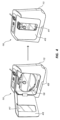
図2~図4は、いくつかの実施形態による、自動尿量測定システム100の尿モニタ110および採尿システム150を示す。
Urine Monitor FIGS. 2-4 illustrate
示されるように、尿モニタ110は、ドレナージレセプタクル154を収容するように構成された空洞214を有するハウジング212を含み得る。ハウジング212の空洞214は、使用中にドレナージレセプタクル154内の尿の観察を妨げることなく、ドレナージレセプタクル154を収容するように構成される。とは言うものの、尿モニタ110は、ドレナージレセプタクル154およびその中の尿を少なくとも部分的に隠すためのオプションの窓417を備えたドア416をさらに含み得る。ドア416がなくても、ハウジング212の空洞214は、特に尿モニタ110がフロアマウント136に取付られている場合、またはIVポールマウント132を介してIVポールに取り付けられている場合に、ドレナージレセプタクル154を床などの潜在的な尿サンプル汚染面から遠ざけるように構成される。
As shown, urine monitor 110 may include
尿モニタ110のハウジング212は、以下でより詳細に説明されるRFIDユニット156を介してドレナージチュービング152を保持するように構成されたRFIDユニットレセプタクル216をさらに含み得る。
図示されていないが、尿モニタ110のハウジング212は、1つまたは複数のバッテリ112を受け入れるように構成されたバッテリコンパートメントと、電源ケーブル114のプラグを受け入れるように構成されたレセプタクルと、ポールマウント132、ベッドレールマウント134、およびフロアスタンド136を支持するように構成された取付インターフェースとをさらに含み得る。
Although not shown,
尿モニタ110は、尿量測定値を含む患者情報を表示するように構成された統合ディスプレイ画面218を含むユーザインターフェースをさらに含むことができ、統合ディスプレイ画面218がタッチスクリーンではない実施形態では、統合ディスプレイ画面218に表示される一つまたは複数のメニュー間を移動するために構成されたキーパッド220をさらに含み得る。
統合ディスプレイ画面218は、基本的なまたは最小限のGUIを有して構成され得る。GUIは、排尿パラメータやその要約などの情報を伝達するように構成され得る。GUIはさらに、尿モニタ110のステータス(例えば、障害アラート)または尿モニタ110によってモニターされている患者のステータス(例えば、健康アラート)などの1つまたは複数のステータスアラートを提供するように構成され得る。GUIの特定のグラフィック要素は、前述の情報を伝達するため、または前述の1つまたは複数のステータスアラートを提供するために、少なくとも10フィート(3.05メートル)の距離から見えるように構成され得る。
尿モニタ110のユーザインターフェースは、さらに、例えば発光ダイオード(「LED」)によって生成される視覚的機能を含み得る。LEDは、尿モニタ110の状態(例えば、尿モニタ110の「オン」状態、尿モニタ110のアクティブな監視状態など)を視覚的に示すように構成される。また、LEDは、空洞214への採尿システム150の完全な配置またはRFIDユニットレセプタクル216へのRFIDユニット156の完全な配置を視覚的に示すように構成される。また、LEDは、ドレナージレセプタクル154を照らすように構成される。また、LEDは、GUIとは別にまたは一緒に尿モニタ110のステータスについて視覚的に警告するように構成される。また、LEDは、GUIとは別にまたは一緒に患者のステータスについて視覚的に警告するように構成される。また、LEDは、それらの組み合わせで構成される。例えば、図2~図4の尿モニタ110は、その底部からドレナージレセプタクル154を直接的に照らすように構成されたLED222のストリップを含む。図2および図3の尿モニタ110はまた、ハウジング212の拡散マテリアルのストリップの後ろに、尿モニタ110の「オン」状態または尿モニタ110のアクティブな監視状態などの尿モニタ110の状態を示すように発光するように構成されたLED224のストリップを含む。図4の尿モニタは、存在する場合LED224のストリップを覆うドア416を含むので、図4の尿モニタ110は、ハウジング212の拡散マテリアルの区画の後ろに、尿モニタ110の状態を示すように発光するように構成されたLED426のセットを含む。尿モニタ110の異なる状態について、LED224または426は、異なる色で点灯するように構成され得、それにより、色分けされた視覚的アラートを提供する。
The user interface of
尿モニタ110のユーザインターフェースは、さらに、例えば1つまたは複数のスピーカによって生成される聴覚的機能を含み得る。スピーカは、尿モニタ110の状態(例えば、尿モニタ110の「オン」状態、尿モニタ110のアクティブな監視状態など)を聴覚的に示す。また、スピーカは、空洞214への採尿システム150の完全な配置またはRFIDユニットレセプタクル216へのRFIDユニット156の完全な配置を聴覚的に示す。また、スピーカは、尿モニタ110のステータスについて聴覚的に警告する。また、スピーカは、患者のステータスについて聴覚的に警告する。また、スピーカは、はそれらの組み合わせを行う。前述の視覚的および聴覚的アラートの任意のアラートについて、尿モニタ110のユーザインターフェースは、聴覚的アラートとは独立した視覚的アラート、視覚的アラートとは独立した聴覚的アラート、または視覚的および聴覚的アラートを一緒に同時に提供するように構成され得る。
The user interface of
尿モニタでの重量基準の尿測定
図5および図6は、いくつかの実施形態による、重量基準の尿測定用に構成された自動尿量測定システム100の尿モニタ510および610をそれぞれ示す。上記の図2~図4の説明など、本明細書に記載の尿モニタ110は、尿モニタ510および610に共通であることを意図していることを理解されたい。尿モニタ510および610は、ドレナージレセプタクル154への尿量を測定するための尿測定手段に関するものを除いて、尿モニタ110の特徴を継承し、これらは、尿モニタ510および610について以下に記載される。
Gravimetric Urine Measurement with Urine Monitors FIGS. 5 and 6 show urine monitors 510 and 610, respectively, of automatic urine volume measurement system 100 configured for gravimetric urine measurement, according to some embodiments. It should be understood that the
図5には直接示されていないが、ドレナージレセプタクル154への尿量を測定するための尿モニタ510の尿測定手段は、重量基準の尿量測定のためのロードセルを含む。ロードセルは、ドレナージレセプタクル154が耐荷重フック528からぶら下がっている間にドレナージレセプタクル154の荷重がロードセルに加えられるように、空洞214の背部に配置された耐荷重フック528に連結される。ロードセルは、耐荷重フック528がドレナージレセプタクル154の荷重をロードセルに加えるメカニズムに応じて、尿モニタ510のハウジング212内に配置された圧縮ロードセルまたは緊張ロードセルのいずれかであり得る。
Although not directly shown in FIG. 5, the urine measurement means of urine monitor 510 for measuring urine volume into
圧縮ロードセルは、圧縮ロードセルが、キーパッド220と、ハウジング212内に延びる耐荷重フック528の隠蔽部分との間に配置されるように、キーパッド220(図示せず)の下においてハウジング212内に取り付けられ得る。
A compression load cell may be mounted within
ドレナージレセプタクル154がハウジング212から空洞214内に延びる耐荷重フック528の露出部分からぶら下がっている場合、耐荷重フック528の隠蔽部分がキーパッド220の下のロードセル内に旋回する一方、耐荷重フック528の露出部分は尿モニタ510の底部に向かって移動し、それにより、ドレナージレセプタクル154の荷重が圧縮ロードセルに直接的に加えられる。
When the
緊張ロードセルは、キーパッド220および耐荷重フック528の隠蔽部分の両方の下においてハウジング212内に取り付けられ、カップリングによって耐荷重フック528の隠蔽部分に連結され得る。
A tension load cell may be mounted within the
ドレナージレセプタクル154が耐荷重フック528の露出部分からぶら下がっている場合、耐荷重フック528の隠蔽部分がキーパッド220に向けて旋回する一方、耐荷重フック528の露出部分は尿モニタ510の底部に向かって移動し、それにより、カップリングによって緊張ロードセルから荷重を引き離すことにより、ドレナージレセプタクル154の荷重が緊張ロードセルに間接的に加えられる。
When the
図6に示すように、ドレナージレセプタクル154への尿量を測定するための尿モニタ610の尿測定手段は、重量基準の尿量測定のための圧縮ロードセル630を含む。圧縮ロードセル630は、尿モニタ610の空洞214の底部に配置されている。ドレナージレセプタクル154が空洞214の底部に位置する場合、ドレナージレセプタクルは圧縮ロードセル630上にも位置し、それにより、ドレナージレセプタクル154の荷重が圧縮ロードセル630に直接加わる。
As shown in FIG. 6, the urine measurement means of the
以下に述べるように、尿モニタ110の組み込みシステム1000のソフトウェアは、圧縮ロードセル630などの圧縮ロードセルまたは緊張ロードセルから経時的にいくつかの重量基準の測定値を収集するように構成され得、重量基準の測定値は、少なくとも29日などの日数の間、組み込みシステム1000に保存され得る。患者の尿量をモニターしている間はいつでも、重量基準の測定値は、例えば、ブルートゥース(BLUETOOTH)(登録商標)またはWi-Fiを介して、コンパニオンワイヤレスデバイス120(例えば、タブレットコンピュータ)に無線通信され得る。尿モニタ110と1つまたは複数のネットワーク化されたコンピュータとの間の仲介デバイスとして、コンパニオンワイヤレスデバイス120は、重量基準の尿量測定値を含む患者情報を有する電子医療記録を更新する、または、電子医療記録から患者の履歴情報を取得する1つまたは複数のソフトウェアプログラムによって構成され得る。さらに、排尿の速度は、重量基準の測定値から尿モニタ110によって計算され得、それはまた、いつでも患者の電子医療記録を更新するために無線通信され得る。
As described below, the embedded system 1000 software of
尿モニタでの体積基準の尿測定
図7は、いくつかの実施形態による、体積基準の尿測定用に構成された自動尿量測定システム100の尿モニタ710を示す。上記の図2~図4の説明など、本明細書に記載の尿モニタ110は、尿モニタ710に共通であることを意図していることを理解されたい。尿モニタ710は、ドレナージレセプタクル154への尿量を測定するための尿測定手段に関するものを除いて、尿モニタ110の特徴を継承し、これらは、尿モニタ710について以下に記載される。
Volume-Based Urine Measurement with a Urine Monitor FIG. 7 illustrates a
図7には直接示されていないが、ドレナージレセプタクル154への尿量を測定するための尿モニタ710の尿測定手段は、体積基準の尿量測定のためにリジッドまたはハードサイドドレナージカセット756を使用する。ドレナージカセット756は、ソフトサイドドレナージバッグ758に流体的に連結され、それによってドレナージレセプタクル154を形成するように構成される。ドレナージバッグ758などのドレナージバッグを収容するように構成された尿モニタ110の空洞214に加えて、尿モニタ710は、ドレナージカセット756を収容するように構成された空洞214の上部延長部715を含む。
Although not directly shown in FIG. 7, the urine measurement means of urine monitor 710 for measuring urine volume into
ドレナージレセプタクル154への尿量を測定するための尿モニタ710の尿測定手段は、体積基準の尿量測定用の、非接触超音波液面センサ、非接触光学液面センサ、またはインライン流量計を含む。超音波液面センサの場合、ドレナージカセット756は、ドレナージチュービング152用のドレナージカセット756の上部のポートに隣接し、超音波液面センサを挿入するためのポートを、ドレナージカセット756の該上部に含み得る。超音波液面センサは、尿モニタ710につながれるか、または単一患者器具とともに提供され、その後、尿モニタ710に接続され得る。光学液面センサの場合、光学液面センサまたはいくつかのそのようなセンサは、ドレナージカセット756の後ろの空洞214の上部延長部715またはドレナージカセット756の側面に埋め込み得る。インライン流量計の場合、インライン流量計は、ドレナージカセット756のドレナージチュービングポートに統合され得る。尿がインライン流量計を通って流れるので、インライン流量計は、単一患者器具とともに提供され、その後、尿モニタ710に接続され得る。
The urine measurement means of urine monitor 710 for measuring urine volume into
以下に記載されるように、尿モニタ110の組み込みシステム1000のソフトウェアは、非接触超音波液面センサ、非接触光学液面センサ、またはインライン流量計から、経時的に多数の体積基準の測定値を収集するように構成され得、体積基準の測定値は、少なくとも29日間などの日数の間、組み込みシステム1000に保存され得る。患者の尿量をモニターしている間はいつでも、体積基準の測定値は、例えば、ブルートゥース(BLUETOOTH)(登録商標)またはWi-Fiを介して、コンパニオンワイヤレスデバイス120(例えば、タブレットコンピュータ)に無線通信され得る。尿モニタ110と1つまたは複数のネットワーク化されたコンピュータとの間の仲介デバイスとして、コンパニオンワイヤレスデバイス120は、体積基準の尿量測定値を含む患者情報を有する電子医療記録を更新する、または、電子医療記録から患者の履歴情報を取得する1つまたは複数のソフトウェアプログラムによって構成され得る。さらに、排尿の速度は、体積基準の測定値から尿モニタ110によって計算することができ、それはまた、いつでも患者の電子医療記録を更新するために無線通信され得る。
As described below, the software of the built-in system 1000 of the
尿モニタにおけるRFIDリーダライタ
図2~図4、図8、図9A、および図9Bは、いくつかの実施形態による、RFIDリーダライタ、ドレナージチュービングストレインリリーフ機能、またはそれらの組み合わせを含む自動尿量測定システム100の尿モニタ110、810、および910を示す。上記の図2~図4の説明など、本明細書に記載の尿モニタ110は、尿モニタ810および910に共通であることを意図していることを理解されたい。尿モニタ810および910は、RFIDリーダライタおよびドレナージチュービングストレインリリーフ機能に関するものを除いて尿モニタ110の特徴を継承し、これらは、尿モニタ110、810、および910について以下に記載される。
RFID Reader/Writer in Urine Monitors FIGS. 2-4, 8, 9A, and 9B show urine monitors 110, 810, and 910 of automated urine volume measurement system 100 that include an RFID reader/writer, drainage tubing strain relief features, or a combination thereof, according to some embodiments. It should be understood that the
図2~図4に示すように、尿モニタ110のハウジング212は、ドレナージチュービング152におけるドレナージレセプタクル154に隣接する部分の周りにRFIDユニット156があるとき、RFIDユニット156(例えば、RFIDビーズ)を保持するように構成されたRFIDユニットレセプタクル216を含み得る。さらに、ハウジング212は、RFIDユニットレセプタクル216を含む横ドレナージチュービングチャネル217を含む。横ドレナージチュービングチャネル217は、RFIDユニット156が、ドレナージチュービング152におけるドレナージレセプタクル154に隣接する部分の周りにあるときに、RFIDユニット156の両側においてドレナージチュービング152を収容するように構成されるとともに、ドレナージチュービング152を案内および支持してその中のねじれを防止することにより、ドレナージチュービング156にひずみ緩和を提供するように構成される。RFIDユニットレセプタクル216は、RFIDユニット156がドレナージチュービング152の周りにあるときにRFIDユニット156を保持するように構成されるので、RFIDユニットレセプタクル216はまた、RFIDユニット156によって横ドレナージチュービングチャネル217にドレナージチュービング152を保持するように構成される。
As shown in FIGS. 2-4,
尿モニタ110は、RFIDユニットレセプタクル216の周りにおいてハウジング212内にRFIDユニットリーダライタ(図示せず)をさらに含み得る。RFIDユニットリーダライタは、RFIDユニット156の存在を識別し、RFIDユニット156から尿量測定値を含む患者情報を読み取り、RFIDユニット156に尿量測定値を含む患者情報を書き込むように構成される。
図8に示されるように、尿モニタ810のハウジング212は、縦ドレナージチュービングチャネル816と、コンパニオンドレナージチュービングスロット817とを含み得る。縦ドレナージチュービングチャネル816およびコンパニオンドレナージチュービングスロット817は、ドレナージチュービング152を収容するとともに、ドレナージチュービング152を案内および支持してその中のねじれを防止することによってドレナージチュービング156にひずみ緩和を提供するように構成される。尿モニタ110のRFIDユニットレセプタクル216とは異なり、縦ドレナージチュービングチャネル816は、RFIDユニットレセプタクル216のようにRFIDユニット156を保持するように構成されていない。代わりに、ドレナージチュービング152の部分における対向部分の周りに位置するRFIDユニット156と、バックアップまたは模造RFIDユニット157とは、RFIDユニット156および157間のわずかな圧縮力によって、ドレナージチュービング152を縦ドレナージチュービングチャネル816に保持するように構成される。RFIDユニット156および157間のわずかな圧縮力は、縦ドレナージチュービングチャネル816内にドレナージチュービング152を配置する前に引っ張ることなどによって、RFIDユニット156および157間のドレナージチュービング152にわずかな引張力を加えることから生じる。
As shown in FIG. 8 ,
尿モニタ810は、RFIDユニット157が模造RFIDユニットであるときにRFIDユニット156および157のための尿モニタ810のいずれかの短辺上などの、縦ドレナージチュービングチャネル816の周りのハウジング212内に、RFIDユニットリーダライタ(図示せず)をさらに含み得る。あるいは、尿モニタ810は、RFIDユニット157がバックアップRFIDユニットであるときにRFIDユニット156および157のための尿モニタ810の両短辺上などの、縦ドレナージチュービングチャネル816の周りのハウジング212内に、2つのRFIDユニットリーダライタ(図示せず)をさらに含み得る。前述のRFIDユニットリーダライタの各RFIDユニットリーダライタは、RFIDユニット156または157の存在を識別し、RFIDユニット156または157から尿量測定値を含む患者情報を読み取り、尿量測定値を含む患者情報をRFIDユニット156または157に書き込むように構成される。
図9Aおよび図9Bに示されるように、尿モニタ910は、尿モニタ910のハウジング212に配置されたRFIDユニットホルダ916を含み得る。RFIDユニットホルダ916は、ドレナージチュービング152におけるドレナージレセプタクル154に隣接する部分の周りにRFIDユニット156があるときに、RFIDユニット156(例えば、RFIDビーズ)を保持するように構成される。RFIDユニットホルダ916は、RFIDユニット156がドレナージチュービング152の周りにあるときにRFIDユニット156を保持するように構成されるので、RFIDユニットホルダ916はまた、ドレナージチュービング152を保持するように構成されるだけでなく、ドレナージチュービング152を案内および支持してその中のねじれを防止することにより、ドレナージチュービング156にひずみ緩和を提供するように構成される。
As shown in FIGS. 9A and 9B, urine monitor 910 may include
尿モニタ910は、RFIDユニットホルダ916内にRFIDユニットリーダライタ(図示せず)をさらに含み得る。RFIDユニットリーダライタは、RFIDユニット156の存在を識別し、RFIDユニット156から尿量測定値を含む患者情報を読み取り、RFIDユニット156に尿量測定値を含む患者情報を書き込むように構成される。
組み込みシステム
図10は、いくつかの実施形態による、尿モニタ110の組み込みシステム1000を示す。
Embedded System FIG. 10 shows an embedded system 1000 of the
示されるように、組み込みシステム1000は、1つまたは複数のプロセッサ1004を有するマイクロコントローラ1002を含み得る。1つまたは複数のプロセッサ1004は、マイクロコントローラ1002のデータを処理するためのRAM1006内の命令に従ってランダムアクセスメモリ(「RAM」)1006またはソリッドステートドライブ(「SSD」)1007などのソリッドステートストレージデバイスからのデータを処理するように構成される。RAM106に加えて、マイクロコントローラ1002は、尿モニタ110を作動させるためのファームウェアなどのソフトウェアを格納するように構成された読み出し専用メモリ(「ROM」)1008を含み得る。
As shown, embedded system 1000 may include a microcontroller 1002 with one or more processors 1004 . The one or more processors 1004 are configured to process data from a solid state storage device such as a random access memory (“RAM”) 1006 or a solid state drive (“SSD”) 1007 according to instructions in RAM 1006 for processing data of the microcontroller 1002. In addition to RAM 106 , microcontroller 1002 may include read-only memory (“ROM”) 1008 configured to store software, such as firmware, for operating
上記のように、尿モニタ110は、ドレナージレセプタクル154への尿量を測定するための重量または体積基準の尿測定手段とともに構成し得、それら尿測定手段のそれぞれは、組み込みシステム1000に通信可能に連結された1つまたは複数のセンサ1010を利用する。例えば、1つまたは複数のセンサ1010は、上記の圧縮ロードセル、緊張ロードセル、非接触超音波液面センサ、非接触光学液面センサ、およびインライン流量計から選択され得る。1つまたは複数のセンサ1010に加えて、組み込みシステム1000は、1つまたは複数のセンサ1010からの信号に安定した基準電圧を提供するように構成された基準電圧(「VREF」)と、1つまたは複数のセンサ1010からの信号を増幅するように構成された増幅器1014と、1つまたは複数のセンサ1010からの信号を1つまたは複数のプロセッサ1004が処理するためのデータに変換するように構成されたアナログ-デジタル変換器(「ADC」)1016と、を含み得る。
As noted above, urine monitor 110 may be configured with gravimetric or volumetric urine measurement means for measuring urine volume into
上記のように、尿モニタ110は、RFIDリーダライタまたは一対のRFIDリーダライタを含むように構成することができ、各RFIDリーダライタは、図10のRFIDリーダライタ1018に示されるように、組み込みシステム1000に通信可能に連結される。 As noted above, urine monitor 110 can be configured to include an RFID reader/writer or a pair of RFID reader/writers, each RFID reader/writer communicatively coupled to embedded system 1000, as shown at RFID reader/writer 1018 in FIG.
組み込みシステム1000は、GUIおよび尿量測定値を含む患者情報の尿モニタ110の統合ディスプレイ画面218への表示を制御するように構成された専用または仮想グラフィックスコントローラ1020と、LED222および224のストリップを制御するように構成されたLEDコントローラ1022と、ペアリングされたとき、コンパニオンワイヤレスデバイス120(例えば、タブレットコンピュータ)と尿量測定値を含む少なくとも患者情報を無線通信するように構成された少なくともブルートゥース(BLUETOOTH)(登録商標)モジュール1024およびWi-Fiモジュール1026から選択された1つまたは複数のワイヤレス通信モジュールと、キーパッド220又は聴覚的アラートに関する上記のスピーカなどのスピーカ1032などの1つまたは複数のI/Oデバイス1030と通信可能に接続するように構成されたI/Oポート1028と、を含み得る。
The embedded system 1000 is configured to wirelessly communicate at least patient information, including urine volume measurements, with a companion wireless device 120 (e.g., tablet computer) when paired with a dedicated or virtual graphics controller 1020 configured to control the display of patient information, including GUI and urine volume measurements, on the
最後に、組み込みシステム1000は、1つまたは複数のバッテリ112と、電源ケーブル114と、少なくとも、1つまたは複数のバッテリ112を充電するため、汎用AC電源からのAC電力を直流(「DC」)に変換するように構成されたACアダプタと、を少なくとも含む電力管理1034を含み得る。
Finally, embedded system 1000 may include power management 1034 including at least one or
自動尿量測定システムの環境
図11は、自動尿量測定システム100が効果的である第1のシナリオを示す。
図12は、自動尿量測定システムが効果的である第2のシナリオを示す。
Automated Urine Volume System Environment FIG. 11 illustrates a first scenario in which the automated urine volume measurement system 100 is effective.
FIG. 12 illustrates a second scenario in which an automated urine volume measurement system would be effective.
示されているように、図11の第1のシナリオには、病室で寝たきりの患者が含まれる。患者は病院ベッドを離れることができないので、自動尿量測定システム100は、IVポールマウント132またはベッドレールマウント134によりIVポールまたはベッドレールに取り付けられているかどうかにかかわらず、病院ベッドの周りの空間を混雑させないように構成され得ることに注目すべきである。 As shown, the first scenario in FIG. 11 involves a bedridden patient in a hospital room. It should be noted that because the patient cannot leave the hospital bed, the automated urine volume measurement system 100, whether attached to an IV pole or bed rail by IV pole mount 132 or bed rail mount 134, can be configured so as not to clutter the space around the hospital bed.
示されているように、図12の第2のシナリオには、病室にいる健常患者が含まれる。患者が病院ベッドを離れることができるため、自動尿量測定システム100は、フロアスタンド136に取り付けられたときに患者と一緒に移動するように構成され得ることに注目すべきである。実際、尿モニタ110は、動作中に前述の病室以外の多くの異なる環境を通る輸送を容易にするように構成され得る。尿モニタ110は、必要に応じて、特定のデータ(例えば、尿量測定)の収集および任意のアラームを制限する輸送モードを有するように構成され得る。
As shown, the second scenario in Figure 12 involves a healthy patient in a hospital room. It should be noted that since the patient can leave the hospital bed, the automatic urine volume measurement system 100 can be configured to travel with the patient when mounted on the floor stand 136 . Indeed, urine monitor 110 can be configured to facilitate transportation through many different environments other than the aforementioned hospital room during operation.
尿除去装置
図13は、いくつかの実施形態による、ドレナージチュービング152から尿を除去するための尿除去装置1300を示す。図14は、図13の尿除去装置1300の吸引エダクタ1302を示す。図15は、図13の尿除去装置1300のリングノズル1304を示す。
Urine Removal Device FIG. 13 shows a
示されるように、尿除去装置1300は、ポート1303を有する吸引エダクタ1302と、ベント1306およびポートコネクタ1308を有するリングノズル1304と、尿メータ1310と、ドレナージチュービング1312およびリングノズル供給チュービング1314の両方とを含み得る。尿除去装置1300は、採尿システム150の一部と見なすことができ、尿除去装置1300は、尿道カテーテル140およびドレナージチュービング152を流体的に接続するポートコネクタ1308をチュービングコネクタのドレナージポートに接続することによって、尿道カテーテル140またはドレナージチュービング152から残留尿を除去するように構成される。図14および図15において流体の流れの矢印によって示されるように、吸引エダクタ1302のポート1303を介して尿除去装置1300に導入された空気は、リングノズル供給チュービング1314を介して尿メータ1310からリングノズル1304に空気を引き込み、これにより、残留尿を尿道カテーテル140またはドレナージチュービング152からチュービングコネクタのドレナージポートを通して除去するための真空が作られる。リングノズル1304のベント1306は、尿道カテーテル140またはドレナージチュービング152から残留尿を除去するための真空を制御するように構成される。
As shown, the
方法
図16~図27は、それぞれ、自動尿量測定システム100の方法1600~2700を提供する。方法1600~2700は、自動尿量測定システム100を使用する特定の面について別々に提示されているが、方法1600~2700は、説明の便宜の問題として別々に提示されていることを理解されたい。自動尿量測定システム100を使用するために、方法1600~2700の任意の方法を、方法1600~2700の他の方法または複数の方法と組み合わせることができる。
Methods FIGS. 16-27 provide methods 1600-2700 of the automated urine volume measurement system 100, respectively. Although methods 1600-2700 are presented separately with respect to specific aspects of using the automated urine volume measurement system 100, it should be understood that methods 1600-2700 are presented separately as a matter of convenience of explanation. Any of the methods 1600-2700 can be combined with any other method or methods of the methods 1600-2700 to use the automated urine volume measurement system 100. FIG.
図16は、いくつかの実施形態による、バッテリが低いときに、自動尿量測定システム100の尿モニタ110内の1つまたは複数の充電式バッテリ112のバッテリを交換するための方法1600を示す。
FIG. 16 illustrates a method 1600 for replacing batteries in one or more
示されるように、方法1600は、自動尿量測定システム100の使用場所、バイオメディカルラボ、中央供給室(「CSR」)などでのいくつかのステップを含む。
方法1600は、尿モニタ110の統合ディスプレイ画面218にメッセージを表示し、看護師などの臨床医にバッテリが低充電バッテリであることを警告する視覚的アラートを提供するステップを含む。方法1600は、低充電バッテリについて臨床医がバイオメディカルラボに通知するステップをさらに含む。方法1600は、任意選択で、臨床医が電源ケーブル114を汎用交流電源のレセプタクルに差し込むステップを含む。方法1600は、バイオメディカルラボの従業員などの人が充電されたバッテリを臨床医のために回収するステップをさらに含む。方法1600は、従業員が低充電バッテリを充電されたバッテリと交換するステップをさらに含む。方法1600は、従業員が低充電バッテリをバイオメディカルラボに戻すステップをさらに含む。図示されていないが、方法1600は、従業員が外部バッテリ充電装置を用いて低充電バッテリを充電するステップをさらに含み得る。
As shown, the method 1600 includes several steps at the site of use of the automated urine volume measurement system 100, biomedical lab, central supply room (“CSR”), and the like.
The method 1600 includes displaying a message on the
図17は、いくつかの実施形態による、自動尿量測定システム100の尿モニタ110のためのルーチン較正テストを実行するための方法1700を示す。
示されるように、方法1700は、自動尿量測定システム100の使用場所で、尿モニタ110のためのルーチン較正テストを定期的に実行することを含む。
FIG. 17 illustrates a method 1700 for performing routine calibration tests for the
As shown, the method 1700 includes periodically performing routine calibration tests for the
図18は、いくつかの実施形態による、尿モニタ110が修理を必要とするときに、自動尿量測定システム100の尿モニタ110を修理するための方法1800を示す。
示されるように、方法1800は、自動尿量測定システム100の使用場所、バイオメディカルラボ、CSRなどでのいくつかのステップを含む。
FIG. 18 illustrates a method 1800 for servicing the
As shown, the method 1800 includes several steps at the site of use of the automated urine volume measurement system 100, biomedical lab, CSR, and the like.
方法1800は、バイオメディカルラボの従業員などの人が使用場所から尿モニタ110を回収するステップを含む。方法1800は、従業員が尿モニタ110の1つまたは複数のユーザ修理可能モジュールを交換するステップをさらに含む。ユーザ修理可能モジュールの交換が成功した場合、方法1800は、従業員が尿モニタ110を使用場所に戻すステップをさらに含む。ユーザ修理可能モジュールの交換が失敗した場合、方法1800はさらに、従業員またはバイオメディカルラボの従業員のような別の人が尿モニタ110を製造業者または別の修理サービス提供者に修理のために送るステップを含む。修理が成功した場合、または交換用の尿モニタ110が提供された場合、方法1800はさらに、従業員が尿モニタ110を使用場所に配達するステップを含む。
Method 1800 includes retrieving urine monitor 110 from the point of use by a person, such as a biomedical lab employee. Method 1800 further includes the employee replacing one or more user-serviceable modules of
図19は、いくつかの実施形態による、バッテリが低いときに、自動尿量測定システム100の尿モニタ110内の1つまたは複数の充電式バッテリ112のバッテリをホットスワップするための方法1900を示す。
FIG. 19 illustrates a method 1900 for hot swapping batteries of one or more
示されるように、方法1900は、尿モニタ110内の1つまたは複数の充電式バッテリ112のバッテリをホットスワップするために、バイオメディカルラボ、CSRなどに、充電されたバッテリの在庫を維持するステップを含む。
As shown, method 1900 includes maintaining an inventory of charged batteries at a biomedical lab, CSR, etc. for hot-swapping one or more
図20は、いくつかの実施形態による、ソフトウェア更新が利用可能である場合に、自動尿量測定システム100の尿モニタ110のソフトウェアを更新するための方法2000を示す。
FIG. 20 illustrates a method 2000 for updating the software of the
示されるように、方法2000は、ソフトウェアアップデートのためソフトウェアバージョン番号をチェックするために、看護師などの臨床医またはバイオメディカルラボ、CSRなどの従業員などの人が、尿モニタ110の統合ディスプレイ画面218のGUIのスプラッシュ画面を見るステップを含む。方法2000は、看護師または従業員が、自動尿量測定システム100の使用場所において、尿モニタ110でソフトウェア更新を実行するステップをさらに含む。
As shown, the method 2000 includes a person such as a clinician such as a nurse or an employee such as a biomedical lab, a CSR viewing a splash screen of the GUI of the
図21は、いくつかの実施形態による、自動尿量測定システム100を使用して患者の尿量をモニターするための方法2100を示す。
示されるように、方法2100は、フォーリーカテーテルがまだ患者に挿入されていない場合、看護師などの臨床医が、尿道カテーテル140、例えば、フォーリーカテーテルを患者に挿入するステップを含む。方法2100はさらに、臨床医が、フォーリーカテーテルから排尿する患者を観察してフォーリーカテーテルが適切に挿入されていることを確認するステップを含む。方法2100は、アクティブ化コンポーネントがまだドレナージチュービング152に取り付けられていない場合、臨床医が、例えば、採尿システム150のドレナージチュービング152に、RFIDユニット156などのアクティブ化コンポーネントを取り付けるステップをさらに含む。方法2100は、臨床医が、例えば、尿モニタ110の統合ディスプレイ画面218のGUIを介して、アクティブ化コンポーネントを患者に関連付けるステップをさらに含む。方法2100はさらに、ドレナージバッグを空洞214内に吊るすことなどによって、臨床医が、ドレナージバッグなどのドレナージレセプタクル154を尿モニタ110のハウジング212の空洞214内に配置するまたは置くステップを含む。方法2100は、患者が排尿した後、臨床医が、ドレナージバッグ内の尿の量を、尿モニタ110の統合ディスプレイ画面218に示される量で確認するステップをさらに含む。尿モニタ110は、ドレナージバッグが尿モニタ110に存在する間、ドレナージバッグ内の尿の量を継続的に記録し、アクティブ化コンポーネントにドレナージバッグ内の尿の量を記録するように構成される。
FIG. 21 illustrates a method 2100 for monitoring a patient's urine output using the automated urine output system 100, according to some embodiments.
As shown, method 2100 includes a clinician, such as a nurse, inserting a urinary catheter 140, eg, a Foley catheter, into the patient if a Foley catheter has not already been inserted into the patient. Method 2100 further includes the clinician observing the patient voiding through the Foley catheter to confirm proper insertion of the Foley catheter. Method 2100 further includes the clinician attaching an activation component, such as
図22は、いくつかの実施形態による、自動尿量測定システム100を使用して患者が尿量についてモニターされているときに患者を移動するための方法2200を示す。
示されるように、方法2200は、看護師などの臨床医が、ドレナージレセプタクル154、例えば、ドレナージバッグを尿モニタ110のハウジング212の空洞214から取り外すステップを含む。方法2200は、少なくとも臨床医が、病院ベッドの患者を回転させる、または患者を別の病院ベッドに移送するステップを含む。方法2200は、任意選択で、採尿システム150が尿モニタ110から離れている間に、臨床医がドレナージバッグから尿を排出するステップを含む。臨床医が前述のステップに従ってドレナージバッグを排出させた場合、方法2200は、臨床医が、尿モニタ110の統合ディスプレイ画面218のGUIに、採尿システム150が尿モニタ110から離れている間にドレナージバッグから排出された尿の量を入力するステップを含む。採尿システム150が尿モニタ110から離れている間に臨床医がドレナージバッグを排出させなかった場合、方法2200は、採尿システム150が尿モニタ110から離れている間にドレナージバッグから排出された尿がなかったことを、臨床医が、尿モニタ110の統合ディスプレイ画面218のGUIに入力するステップを含み得る。
FIG. 22 illustrates a method 2200 for moving a patient when the patient is being monitored for urine volume using the automated urine volume measurement system 100, according to some embodiments.
As shown, method 2200 includes a clinician, such as a nurse, removing a
図23は、いくつかの実施形態による、自動尿量測定システム100を使用して患者の尿量をモニターするための方法2300を示す。
示されるように、方法2300は、看護師などの臨床医が、尿モニタ110の統合ディスプレイ画面218を毎時に見ることによって患者の尿量をモニターし、尿量測定値を含む患者情報を読み取り、少なくとも尿量測定値を記録するステップを含む。カウントダウンタイマが尿モニタ110の統合ディスプレイ画面218に実装される場合、方法2300は、必要であれば少なくともドレナージバッグから尿を排出するために、臨床医が、ドレナージバッグなどのドレナージレセプタクル154をチェックするステップを任意選択で含む。方法2300はさらに、臨床医が、尿量測定値を含む過去の患者情報または異なるフォーマットで患者情報を見るために、尿モニタ110の統合ディスプレイ画面218のGUIと相互作用するステップを含む。
FIG. 23 illustrates a method 2300 for monitoring a patient's urine volume using the automated urine volume measurement system 100, according to some embodiments.
As shown, the method 2300 includes the steps of a clinician, such as a nurse, monitoring a patient's urine volume by viewing the
図24は、いくつかの実施形態による、自動尿量測定システム100を使用して患者の尿量をモニターしているときにアラートに応答するための方法2400を示す。
示されるように、方法2400は、看護師などの臨床医が、そのアラートが生成されたものに従い、例えば、視覚的アラートといったアラートに応答するステップを含む。あるいは、方法2400は、臨床医がアラートを抑えるステップを含む。
FIG. 24 illustrates a method 2400 for responding to alerts while monitoring a patient's urine volume using the automated urine volume measurement system 100, according to some embodiments.
As shown, method 2400 includes a clinician, such as a nurse, responding to an alert, eg, a visual alert, according to what generated the alert. Alternatively, method 2400 includes the clinician suppressing the alert.
図25は、いくつかの実施形態による、自動尿量測定システム100を使用して患者の尿量をモニターしているときに患者情報を更新するための方法2500を示す。
示されるように、方法2500は、看護師などの臨床医が、尿モニタ110の統合ディスプレイ画面218のGUIにおける、例えば患者の体重といった患者情報を更新するステップを含む。
FIG. 25 illustrates a method 2500 for updating patient information when monitoring a patient's urine volume using the automated urine volume measurement system 100, according to some embodiments.
As shown, method 2500 includes a clinician, such as a nurse, updating patient information, eg, patient weight, in the GUI of
図26は、いくつかの実施形態による、自動尿量測定システム100を使用して患者の尿量をモニターしているときに、尿で満たされたドレナージレセプタクル154を排出するための方法2600を示す。
FIG. 26 illustrates a method 2600 for draining a urine-filled
示されるように、方法2600は、ドレナージバッグを排出させる必要があるときに、看護師などの臨床医が、例えば、尿で満たされたドレナージバッグといった、尿で満たされたドレナージレセプタクル154を排出するステップを含む。臨床医が尿で満たされたドレナージバッグを排出している間、尿モニタ110の統合ディスプレイ画面218のGUIは、方法2600の別のステップでドレナージバッグが排出されているというメッセージを表示する。代替的または追加的に、方法2600は、汚水が最近排出されたというメッセージを、尿モニタ110の統合ディスプレイ画面218のGUIが表示するステップを含む。
As shown, the method 2600 includes a clinician, such as a nurse, draining a urine-filled
図27は、いくつかの実施形態による、自動尿量測定システム100を使用した患者の尿量のモニターを終了させるための方法2700を示す。
示されるように、方法2600は、看護師などの臨床医が、尿道カテーテル140、例えば、フォーリーカテーテルを患者から取り外し、そのフォーリーカテーテルを医療廃棄物のための適切な廃棄物容器に配置するステップを含む。
FIG. 27 illustrates a method 2700 for terminating patient urine volume monitoring using the automated urine volume measurement system 100, according to some embodiments.
As shown, method 2600 includes a clinician, such as a nurse, removing a urinary catheter 140, eg, a Foley catheter, from a patient and placing the Foley catheter in an appropriate waste container for medical waste.
前述の方法のいくつかは、臨床医などの行為者またはバイオメディカルラボ、CSRなどの従業員などの人を含むが、そのような方法それぞれは、少なくともその臨床医または従業員を含むことを理解されたい。言い換えれば、そのような方法における臨床医または従業員は、1つまたは複数の状況に応じて、複数人の臨床医または従業員であり得る。例えば、そのような方法における臨床医または従業員は、シフトの変化、例えば、日勤から半夜勤への変化のために、2人の異なる臨床医または従業員であり得る。 While some of the aforementioned methods involve actors such as clinicians or persons such as employees of biomedical labs, CSRs, etc., it should be understood that each such method includes at least the clinician or employee thereof. In other words, the clinician or employee in such methods may be multiple clinicians or employees, depending on one or more circumstances. For example, the clinicians or employees in such methods may be two different clinicians or employees due to shift changes, eg, day shift to half-night shift.
いくつかの特定の実施形態が本明細書に開示されており、特定の実施形態がある程度詳細に開示されているが、特定の実施形態が本明細書で提供される概念の範囲を制限することは意図されていない。付加的な適応および/または修正が当業者に理解することができ、より広い態様では、これらの適応および/または修正もまた包含される。したがって、本明細書で提供される概念の範囲から逸脱することなく、本明細書で開示される特定の実施形態から逸脱することができる。 Although a number of specific embodiments are disclosed herein, and specific embodiments are disclosed in some detail, the specific embodiments are not intended to limit the scope of the concepts provided herein. Additional adaptations and/or modifications may be appreciated by those skilled in the art, and are also encompassed in the broader aspects. Accordingly, departures may be made from the specific embodiments disclosed herein without departing from the scope of the concepts provided herein.
Claims (16)
a)単一患者器具であって、
尿道カテーテルと、
ドレナージチュービングおよびドレナージレセプタクルを含む採尿システムと、
を含む単一患者器具と、
b)複数患者器具であって、尿モニタを含み、前記尿モニタは、
前記ドレナージレセプタクルを収容するように構成された空洞を有するハウジングと、
前記ドレナージレセプタクルへの尿量を測定するための尿測定手段と、
尿量測定値を含む患者情報を表示するように構成された統合ディスプレイ画面と、
を含む複数患者器具と、
を備え、
前記尿モニタは、無線周波数識別(「RFID」)ユニットリーダライタを含み、前記RFIDユニットリーダライタは、前記採尿システムに統合されたRFIDユニットの存在を識別し、前記RFIDユニットからデータを読み取り、前記RFIDユニットにデータを書き込むように構成され、
前記RFIDユニットは、前記ドレナージチュービングにおける前記ドレナージレセプタクルに隣接する部分の周りのビーズである自動尿量測定システム。 An automatic urine volume measurement system,
a) a single-patient device,
urinary catheter and
a urine collection system including drainage tubing and a drainage receptacle;
a single-patient device comprising
b) a multi-patient device comprising a urine monitor, said urine monitor comprising:
a housing having a cavity configured to receive the drainage receptacle;
urine measuring means for measuring urine volume into the drainage receptacle;
an integrated display screen configured to display patient information including urine volume measurements;
a multi-patient device comprising
with
the urine monitor includes a radio frequency identification (“RFID”) unit reader/writer configured to identify the presence of, read data from, and write data to an RFID unit integrated with the urine collection system;
An automated urine volume measurement system wherein the RFID unit is a bead around a portion of the drainage tubing adjacent the drainage receptacle .
a)単一患者器具であって、尿道カテーテルおよび採尿システムを備え、前記採尿システムは、
ドレナージチュービングと、
ドレナージバッグと、
前記ドレナージチュービングにおける前記ドレナージバッグに隣接する部分の周りのオプションの無線周波数識別(「RFID」)ビーズと、
を含む単一患者器具と、
b)複数患者器具であって、
尿モニタであって、
前記ドレナージバッグを収容するように構成された空洞と、前記RFIDビーズがあるときに前記RFIDビーズによって前記ドレナージチュービングを保持するように構成されたRFIDビーズレセプタクルとを有するハウジングと、
前記ハウジング内に配置された緊張ロードセルであって、前記空洞の背部に位置する耐荷重フックに連結され、前記ドレナージバッグが前記耐荷重フックからぶら下がっているときに前記ドレナージバッグの荷重を前記ロードセルに加えることによって前記ドレナージバッグへの尿量を測定するように構成された緊張ロードセルと、
前記RFIDビーズの存在を識別し、前記RFIDビーズから患者情報を読み取り、前記RFIDビーズに患者情報を書き込むように構成されたRFIDビーズリーダライタと、
尿量測定値を含む患者情報を表示するように構成された統合ディスプレイ画面と、
を含む尿モニタと、
尿量を含む患者情報を有する電子医療記録を更新するため又は前記電子医療記録から過去の患者情報を取得するため、前記尿モニタおよび1つまたは複数のネットワーク化されたコンピュータと無線通信するように構成されたコンパニオンタブレットコンピュータと、
を含む複数患者器具と、
を備える自動尿量測定システム。 An automatic urine volume measurement system,
a) a single-patient device comprising a urinary catheter and a urine collection system, said urine collection system comprising:
drainage tubing;
a drainage bag and
optional radio frequency identification (“RFID”) beads around a portion of the drainage tubing adjacent the drainage bag;
a single-patient device comprising
b) a multi-patient device comprising:
a urine monitor,
a housing having a cavity configured to house the drainage bag and an RFID bead receptacle configured to hold the drainage tubing by the RFID bead when the RFID bead is present;
a tension load cell disposed within the housing and coupled to a load bearing hook located at the back of the cavity and configured to measure urine volume into the drainage bag by applying a load of the drainage bag to the load cell when the drainage bag is suspended from the load bearing hook;
an RFID bead reader/writer configured to identify the presence of the RFID bead, read patient information from the RFID bead, and write patient information to the RFID bead;
an integrated display screen configured to display patient information including urine volume measurements;
a urine monitor comprising
a companion tablet computer configured to wirelessly communicate with the urine monitor and one or more networked computers to update an electronic medical record with patient information, including urine volume, or to obtain historical patient information from the electronic medical record;
a multi-patient device comprising
Automated urine volume measurement system with
Priority Applications (1)
| Application Number | Priority Date | Filing Date | Title |
|---|---|---|---|
| JP2023114625A JP2023126414A (en) | 2018-08-10 | 2023-07-12 | Automated urine-output-measurement system |
Applications Claiming Priority (3)
| Application Number | Priority Date | Filing Date | Title |
|---|---|---|---|
| US201862717678P | 2018-08-10 | 2018-08-10 | |
| US62/717,678 | 2018-08-10 | ||
| PCT/US2019/045787 WO2020033752A1 (en) | 2018-08-10 | 2019-08-08 | Automated urine-output-measurement systems and methods thereof |
Related Child Applications (1)
| Application Number | Title | Priority Date | Filing Date |
|---|---|---|---|
| JP2023114625A Division JP2023126414A (en) | 2018-08-10 | 2023-07-12 | Automated urine-output-measurement system |
Publications (2)
| Publication Number | Publication Date |
|---|---|
| JP2021533865A JP2021533865A (en) | 2021-12-09 |
| JP7314252B2 true JP7314252B2 (en) | 2023-07-25 |
Family
ID=69415145
Family Applications (2)
| Application Number | Title | Priority Date | Filing Date |
|---|---|---|---|
| JP2021506723A Active JP7314252B2 (en) | 2018-08-10 | 2019-08-08 | Automatic urine volume measurement system |
| JP2023114625A Pending JP2023126414A (en) | 2018-08-10 | 2023-07-12 | Automated urine-output-measurement system |
Family Applications After (1)
| Application Number | Title | Priority Date | Filing Date |
|---|---|---|---|
| JP2023114625A Pending JP2023126414A (en) | 2018-08-10 | 2023-07-12 | Automated urine-output-measurement system |
Country Status (5)
| Country | Link |
|---|---|
| US (2) | US11911160B2 (en) |
| EP (1) | EP3833257A4 (en) |
| JP (2) | JP7314252B2 (en) |
| CN (1) | CN112566550A (en) |
| WO (1) | WO2020033752A1 (en) |
Families Citing this family (12)
| Publication number | Priority date | Publication date | Assignee | Title |
|---|---|---|---|---|
| BR112020022290A2 (en) | 2018-05-01 | 2021-02-23 | Purewick Corporation | fluid collection devices, related systems, and related methods |
| US11717642B2 (en) | 2020-04-24 | 2023-08-08 | Covidien Lp | Catheter including one or more sensors |
| US11744498B2 (en) | 2020-07-17 | 2023-09-05 | Covidien Lp | Catheter system |
| US20220142843A1 (en) * | 2020-11-11 | 2022-05-12 | Purewick Corporation | Urine collection system including a flow meter and related methods |
| US11944737B2 (en) | 2020-11-24 | 2024-04-02 | C. R. Bard, Inc. | Air venting meter lid adapter |
| US11931541B2 (en) | 2021-01-08 | 2024-03-19 | C. R. Bard, Inc. | Connector for selective occlusion of drainage tube |
| CN112880794B (en) * | 2021-01-18 | 2022-04-22 | 徐州市中心医院 | Intelligent urine volume accurate metering device for critical patient |
| EP4322854A1 (en) * | 2021-04-15 | 2024-02-21 | Reprieve Cardiovascular, Inc. | Urine collection systems and associated methods and devices |
| WO2023076067A1 (en) * | 2021-10-25 | 2023-05-04 | C. R. Bard, Inc. | Automated urinary output monitoring system |
| WO2023086394A1 (en) * | 2021-11-10 | 2023-05-19 | C.R. Bard, Inc. | Urinary output monitoring system |
| GB2615068A (en) * | 2022-01-19 | 2023-08-02 | Salts Healthcare Ltd | An ostomy collection volume stand |
| CN115112909B (en) * | 2022-06-27 | 2023-05-16 | 江西康唛迪生物科技有限公司 | Dynamic urine monitor |
Citations (7)
| Publication number | Priority date | Publication date | Assignee | Title |
|---|---|---|---|---|
| JP2006317224A (en) | 2005-05-11 | 2006-11-24 | Aichi Tokei Denki Co Ltd | Medical tube for flow measurement, medical container for flow measurement, and apparatus for measuring drainage flow |
| JP2008099781A (en) | 2006-10-18 | 2008-05-01 | Terumo Corp | Urethral catheterization bag carrying container |
| JP2008206592A (en) | 2007-02-23 | 2008-09-11 | Yoshihiko Hirao | Measuring system and program |
| JP2012105947A (en) | 2010-10-27 | 2012-06-07 | Sasae Ishibashi | Container for urine collection, and urinary volume measuring device |
| WO2014043650A2 (en) | 2012-09-17 | 2014-03-20 | Theranova, Llc | Systems, devices and methods for urine monitoring |
| JP2017536857A (en) | 2014-09-28 | 2017-12-14 | ポトレロ メディカル,インコーポレイテッド | Systems, devices, and methods for sensing physiological data, draining and analyzing body fluids |
| US20180214297A1 (en) | 2015-07-31 | 2018-08-02 | Medivance Incorporated | Urine output collection and monitoring system |
Family Cites Families (216)
| Publication number | Priority date | Publication date | Assignee | Title |
|---|---|---|---|---|
| US3661143A (en) | 1969-06-23 | 1972-05-09 | Henkin Melvyn Lane | Medical apparatus for drainage, collection and monitoring of body fluids |
| US3851650A (en) | 1972-06-06 | 1974-12-03 | Kendall & Co | Closed drainage system with double lumen tube |
| US3781920A (en) | 1972-06-21 | 1974-01-01 | Brown Eng Corp | Waste discharge valve for toilet bowl |
| US3919455A (en) | 1972-10-20 | 1975-11-11 | Hoffmann La Roche | Apparatus for the measurement of the volume and flow rate of liquids |
| CH558005A (en) | 1972-10-20 | 1975-01-15 | Hoffmann La Roche | DEVICE FOR DETERMINING THE FLOW RATE OF A FLOWING LIQUID. |
| JPS54147066A (en) | 1978-05-11 | 1979-11-16 | Shinko Electric Co Ltd | Level detector |
| JPS5516669A (en) | 1978-07-24 | 1980-02-05 | Terumo Corp | Intravenous drip measuring device |
| US4276889A (en) | 1979-04-19 | 1981-07-07 | Shs Enterprises, Ltd. | Urine specimen collecting device |
| US4291692A (en) | 1979-10-09 | 1981-09-29 | University Of Utah | Closed-loop infusion system, both method and apparatus, based on real time urine measurement |
| US4312352A (en) | 1980-01-29 | 1982-01-26 | C. R. Bard, Inc. | Hanger, hook and handle assembly for urinary drainage bag |
| US4305405A (en) | 1980-03-25 | 1981-12-15 | C. R. Bard, Inc. | Urine meter bag |
| US4343316A (en) | 1980-05-16 | 1982-08-10 | C. R. Bard, Inc. | Electronic urine flow monitor |
| EP0041487A1 (en) | 1980-05-29 | 1981-12-09 | Hans-Peter Scholander | Catheter device |
| US4296749A (en) | 1980-07-18 | 1981-10-27 | Louis B. Fine | Colostomy appliance |
| US4443219A (en) | 1981-03-10 | 1984-04-17 | C. R. Bard, Inc. | System for aseptically draining a urine bag |
| US4532936A (en) | 1981-08-21 | 1985-08-06 | Leveen Eric G | Automatic urine flow meter |
| US4375291A (en) | 1981-09-08 | 1983-03-01 | Borg-Warner Corporation | Back-up mechanical seal |
| US4448207A (en) | 1981-11-03 | 1984-05-15 | Vital Metrics, Inc. | Medical fluid measuring system |
| JPS58190719A (en) | 1982-04-30 | 1983-11-07 | Nippon Steel Corp | Two-phase flow meter for two-phase fluid such as gas-liquid, solid-liquid and solid-gas fluids |
| US4658834A (en) | 1983-03-16 | 1987-04-21 | C.R. Bard, Inc. | Medical apparatus for monitoring body liquid discharge |
| JPS60219517A (en) | 1984-04-16 | 1985-11-02 | Matsushita Electric Ind Co Ltd | Bath boiler with water level detector |
| US5002541A (en) | 1984-06-19 | 1991-03-26 | Martin And Associates, Inc. | Method and device for removing and collecting urine |
| US4723950A (en) | 1984-12-12 | 1988-02-09 | C. R. Bard, Inc. | Urine drainage bag outlet with barrier against microbial infection |
| US4850375A (en) | 1987-11-09 | 1989-07-25 | The Kendall Company | Urine meter with tilting guide |
| US4834706A (en) | 1987-11-24 | 1989-05-30 | Sherwood Medical Company | Medical apparatus with a tearable tamper evident indicator means |
| AU620613B2 (en) | 1988-05-12 | 1992-02-20 | Dacomed Corporation | Urine collection monitor |
| US4889532A (en) | 1988-06-21 | 1989-12-26 | Hollister Incorporated | Female urinary incontinence device with forwardly-directed discharge passage and support surface portions |
| US5586085A (en) | 1991-10-31 | 1996-12-17 | Lichte; Leo J. | Container and adaptor for use with fluid volume sensor |
| DE4306478A1 (en) | 1993-03-02 | 1994-09-08 | Wolfgang Dr Wagner | Drainage device, in particular pleural drainage device, and drainage method |
| US5409014A (en) | 1993-08-13 | 1995-04-25 | Dravon Medical, Inc. | Fluid meter |
| DE4338687C1 (en) | 1993-11-12 | 1995-07-06 | Fresenius Ag | Urine meter and method for determining the density of urine |
| DK53094A (en) | 1994-05-06 | 1995-11-07 | Uno Plast As | Apparatus for measuring and collecting body fluid |
| JPH08271301A (en) | 1995-03-30 | 1996-10-18 | Chichibu Onoda Cement Corp | Flow measuring device for powder/grain |
| US5725515A (en) | 1994-11-01 | 1998-03-10 | Tri-State Hospital Supply Corporation | Urine sampling and bladder drainage system |
| US8280682B2 (en) | 2000-12-15 | 2012-10-02 | Tvipr, Llc | Device for monitoring movement of shipped goods |
| DE19511556C1 (en) | 1995-03-29 | 1996-07-25 | Daimler Benz Ag | Electrical sensor for determn. of state of liq. in container |
| US5891051A (en) | 1995-06-02 | 1999-04-06 | C.R. Bard, Inc. | Electronic urine monitor |
| CA2186805C (en) | 1995-12-01 | 2001-03-27 | Christopher C. Jung | Apparatus and method for sensing fluid level |
| US5733319A (en) | 1996-04-25 | 1998-03-31 | Urologix, Inc. | Liquid coolant supply system |
| US5823972A (en) | 1996-06-06 | 1998-10-20 | Mcrae; Lorin P. | Pressure transducer bladder pressure and urinary flow measurement apparatus and method |
| US5807278A (en) | 1996-06-06 | 1998-09-15 | Mcrae; Lorin P. | Noninvasive bladder pressure and urine flow measurement apparatus and method |
| JPH10104041A (en) | 1996-09-27 | 1998-04-24 | Sofue Yatoshi | Liquid amount detector and instillation end alarm |
| US6132407A (en) | 1997-02-06 | 2000-10-17 | C. R. Bard, Inc. | Outlet tube device for urinary drainage bag |
| IL124703A0 (en) | 1998-06-01 | 1999-01-26 | Abramovitch Aron | Method and device for measurement of urine bladder functions and urination |
| DE19839962C1 (en) | 1998-09-02 | 2000-04-27 | Braun Melsungen Ag | Urine meter |
| US6709420B1 (en) | 1999-07-21 | 2004-03-23 | C.R. Bard, Inc. | Switch-style drain assembly for urine collection container |
| US6261254B1 (en) | 1999-07-21 | 2001-07-17 | C. R. Bard, Inc. | Lever-style drain assembly for urine collection container |
| KR100333166B1 (en) | 1999-07-29 | 2002-04-18 | 차기철 | Useful Apparatus and Method for Analyzing Body Composition Based on Bioelectrical Impedance |
| FI110305B (en) | 2000-02-17 | 2002-12-31 | Instrumentarium Oyj | Device in a monitoring monitor for a patient |
| US6434418B1 (en) | 2000-04-12 | 2002-08-13 | Randall H. Neal | Apparatus for measuring intrauterine pressure and fetal heart rate and method for using same |
| US20010056226A1 (en) | 2000-04-18 | 2001-12-27 | Richard Zodnik | Integrated telemedicine computer system |
| US6592612B1 (en) | 2000-05-04 | 2003-07-15 | Cardeon Corporation | Method and apparatus for providing heat exchange within a catheter body |
| US20020016719A1 (en) | 2000-06-19 | 2002-02-07 | Nemeth Louis G. | Methods and systems for providing medical data to a third party in accordance with configurable distribution parameters |
| CN2445749Y (en) | 2000-08-17 | 2001-09-05 | 吴兴 | Medical electric pump transfusion system |
| AU2002247016A1 (en) | 2001-01-24 | 2002-08-06 | Virginia Commonwealth University | Molecular imprinting of small particles, and production of small particles from solid state reactants |
| GR1003802B (en) | 2001-04-17 | 2002-02-08 | Micrel �.�.�. ������� ��������� ��������������� ��������� | Tele-medicine system |
| US6537262B2 (en) | 2001-06-13 | 2003-03-25 | Garey Thompson | Female urine collector |
| US6539797B2 (en) | 2001-06-25 | 2003-04-01 | Becs Technology, Inc. | Auto-compensating capacitive level sensor |
| ITMI20012829A1 (en) | 2001-12-28 | 2003-06-28 | Gambro Dasco Spa | APPARATUS AND METHOD OF CONTROL IN A BLOOD EXTRACORPOREAL CIRCUIT |
| US6716200B2 (en) | 2002-01-18 | 2004-04-06 | C.R. Bard, Inc. | Antimicrobial urine collection system and methods of manufacturing the same |
| JP2005517939A (en) | 2002-02-20 | 2005-06-16 | レビンソン オーデ | Urine sample collection device |
| US6692518B2 (en) | 2002-02-27 | 2004-02-17 | Medivance Incorporated | Patient temperature control system |
| US7998126B1 (en) | 2002-11-06 | 2011-08-16 | Benidecto Fernandez | Integral urine collector |
| WO2004045410A1 (en) | 2002-11-19 | 2004-06-03 | Urodan Aps | An apparatus and a method for urological measurements |
| US7011634B2 (en) | 2003-04-14 | 2006-03-14 | Sample Rite, Inc. | Urine sample collection device |
| US7494459B2 (en) | 2003-06-26 | 2009-02-24 | Biophan Technologies, Inc. | Sensor-equipped and algorithm-controlled direct mechanical ventricular assist device |
| WO2005037556A2 (en) | 2003-08-25 | 2005-04-28 | Medivance, Incorporated | Active body cooling with vasodilation to reduce body temperature |
| JP4590352B2 (en) | 2003-12-22 | 2010-12-01 | メデラ ホールディング アーゲー | Drainage device and method |
| US7258005B2 (en) | 2004-02-06 | 2007-08-21 | David Scott Nyce | Isolated capacitive fluid level sensor |
| US20060100743A1 (en) | 2004-04-23 | 2006-05-11 | Renal Diagnostic Inc. | Automated non-invasive real-time acute renal failure detection system |
| EP1593345B1 (en) | 2004-05-07 | 2007-02-21 | Transmed Medizintechnik GmbH & Co. KG | Automatic liquid flow monitor, especially for urine |
| NL1026506C1 (en) | 2004-06-25 | 2005-12-28 | Dijkman Holding B V | Device for measuring data relating to the urine production of a patient. |
| US7977529B2 (en) | 2004-11-03 | 2011-07-12 | Fred Bergman Healthcare Pty Ltd. | Incontinence management system and diaper |
| EP1677083A1 (en) | 2004-12-22 | 2006-07-05 | Roxer Industries S.A. | Flüssigkeitspegelsensor |
| IL166400A (en) | 2005-01-20 | 2012-07-31 | Flowsense Ltd | Optical drop detection system |
| US8813551B2 (en) | 2005-04-10 | 2014-08-26 | Future Path Medical Holding Co. Llc | Device that accurately measures physiological fluid flow |
| US7931630B2 (en) | 2005-07-05 | 2011-04-26 | C. R. Bard, Inc. | Multi-functional and modular urine collection system |
| US20100137743A1 (en) | 2005-07-05 | 2010-06-03 | C. R. Bard, Inc. | Multi-functional and modular urine collection system |
| CA2619979A1 (en) | 2005-08-31 | 2007-03-08 | Venetec International, Inc. | Anchoring system for a catheter |
| US20120095304A1 (en) | 2005-12-15 | 2012-04-19 | Cardiopulmonary Corporation | System and Method for Determining a Patient Clinical Status |
| US20070145137A1 (en) | 2005-12-27 | 2007-06-28 | Mrowiec Zbigniew R | Systems and methods for processing measurement data |
| US8328734B2 (en) | 2006-02-24 | 2012-12-11 | Covidien Lp | Urine meter with improved drain construction |
| CA2882654C (en) | 2006-04-14 | 2017-06-13 | Deka Products Limited Partnership | Systems, devices and methods for fluid pumping, heat exchange, thermal sensing, and conductivity sensing |
| US7522061B2 (en) | 2006-04-28 | 2009-04-21 | Medtronic, Inc. | External voiding sensor system |
| JP2007303982A (en) | 2006-05-12 | 2007-11-22 | Kougi Kenkyusho:Kk | Sensor device |
| CN200951235Y (en) | 2006-08-22 | 2007-09-26 | 张念 | Electric capacity intelligent sensing device for automatic control system for intravenous drip |
| GB2440842B (en) | 2006-09-30 | 2008-08-20 | Funnelly Enough Ltd | Urine collection device |
| CA2669516A1 (en) | 2006-11-14 | 2008-05-22 | Med-I-Dynamix Fluid Monitoring Ltd. | A diagnostic method and apparatus |
| WO2008073718A2 (en) | 2006-11-29 | 2008-06-19 | Future Path Medical Llc | Container for physiological fluids |
| WO2008103625A2 (en) | 2007-02-21 | 2008-08-28 | C.R. Bard, Inc. | Acs therapy system |
| US20080276362A1 (en) | 2007-05-10 | 2008-11-13 | O'malley Conor | Mechanically sealable rapid opening stagger-flush residential toilet |
| US8295933B2 (en) | 2007-05-30 | 2012-10-23 | Medtronic, Inc. | Implantable medical lead including voiding event sensor |
| JP5371972B2 (en) | 2007-06-22 | 2013-12-18 | ベクトン・ディキンソン・アンド・カンパニー | Dispensing volume monitor for array arrangement |
| IL185477A0 (en) | 2007-08-23 | 2008-01-06 | Med I Dynamix Fluid Monitoring | Diagnostic methods and systems based on urine analysis |
| FR2920535B1 (en) | 2007-08-30 | 2009-11-27 | Hill Rom Ind Sa | PRESSURE DETECTION AND MEASURING SENSOR INCORPORATING AT LEAST ONE RESISTIVE FORCE DETECTION CELL |
| JP4614997B2 (en) | 2007-09-12 | 2011-01-19 | 新東工業株式会社 | Powder flow rate measuring device and measuring method thereof |
| EP2037281B1 (en) | 2007-09-13 | 2018-10-10 | Sysmex Corporation | Sample analyzer |
| US8374688B2 (en) | 2007-09-14 | 2013-02-12 | Corventis, Inc. | System and methods for wireless body fluid monitoring |
| WO2009046176A1 (en) | 2007-10-02 | 2009-04-09 | C. R. Bard, Inc. | Drainage catheter with one-way valve |
| WO2009049245A1 (en) | 2007-10-11 | 2009-04-16 | Optiscan Biomedical Corporation | Synchronization and configuration of patient monitoring devices |
| EP3677228A1 (en) | 2007-10-12 | 2020-07-08 | Medivance Incorporated | Improved system for patient temperature control |
| US7437945B1 (en) | 2008-02-14 | 2008-10-21 | Murray F Feller | Magnetic flow probe |
| US8162922B2 (en) * | 2008-05-07 | 2012-04-24 | Sacco John S | CUI-tagged catheter devices and system |
| US20090287170A1 (en) | 2008-05-13 | 2009-11-19 | Preferred Medical Devices, Inc. | Urine collection system |
| EP2293827A4 (en) | 2008-05-16 | 2017-08-16 | Maurice M. Garcia | Catheter drainage system |
| US20110251572A1 (en) | 2008-06-06 | 2011-10-13 | C.R. Bard, Inc. | Urine Collection Device |
| US8192368B2 (en) | 2008-06-09 | 2012-06-05 | Gentera Holdings, Llc | Pressure sensing catheter |
| WO2010002393A1 (en) | 2008-06-30 | 2010-01-07 | Venetec International, Inc. | Anchoring system for a medical article |
| US8357105B2 (en) | 2008-08-07 | 2013-01-22 | Covidien Lp | Anti-reflux mechanism for urine collection systems |
| US8832558B2 (en) | 2008-10-12 | 2014-09-09 | University Of Maryland, Baltimore | Predetermined presentation of patient data at bedside |
| WO2010045042A2 (en) | 2008-10-17 | 2010-04-22 | Sterigear LLC | Bodily fluid drainage assembly |
| JP2010121950A (en) | 2008-11-17 | 2010-06-03 | Loarant Corp | Device of measuring amount of liquid |
| WO2010111778A1 (en) | 2009-03-30 | 2010-10-07 | Steve Andre Beaudin | Apparatus. system and methods for extracorporeal blood processing for selectively cooling the brain relative to the body during hyperthermic treatment or to induce hypothermia of the brain |
| US8721605B2 (en) | 2009-04-27 | 2014-05-13 | The Alfred E. Mann Foundation For Scientific Research | Implantable infusion devices with palpable landmarks and methods of needle detection |
| WO2010141458A2 (en) | 2009-06-03 | 2010-12-09 | Biometrix Ltd | Apparatus and method for bedside collection of body fluids and automatic volume level monitoring |
| SE534493C2 (en) | 2009-06-23 | 2011-09-06 | Observe Medical Aps | Device and method for measuring urine production in patients carrying urinary catheters |
| EP2456353B1 (en) | 2009-07-24 | 2016-07-20 | Flometrica Ltd. | Disposable usb cup |
| CN201492414U (en) | 2009-07-31 | 2010-06-02 | 成都卓青科技有限公司 | Urine automatic meter |
| US8337476B2 (en) | 2009-08-20 | 2012-12-25 | Greenwald Technologies, Llc | Real time urine monitoring system |
| WO2011044259A1 (en) | 2009-10-06 | 2011-04-14 | Venetec International, Inc. | Stabilizing device having a locking collet |
| US8978172B2 (en) | 2009-11-17 | 2015-03-17 | Kohler Co. | Plumbing fixture having modular control housing |
| US8773259B2 (en) | 2009-12-23 | 2014-07-08 | Mindray Ds Usa, Inc. | Systems and methods for remote patient monitoring |
| JP5523908B2 (en) | 2010-04-13 | 2014-06-18 | 三菱重工業株式会社 | Flow rate measuring device and flow velocity measuring device |
| WO2011150285A1 (en) | 2010-05-26 | 2011-12-01 | Adm Tronics Unlimited Inc. | Apparatus and method for uroflowmetry |
| WO2012013662A1 (en) | 2010-07-26 | 2012-02-02 | Steerable Instruments Bvba | Capillary tube assembly |
| WO2012016179A1 (en) | 2010-07-30 | 2012-02-02 | C.R. Bard, Inc. | Automated method of pooling elimination with a biological fluid collection system |
| US8518020B2 (en) | 2010-08-23 | 2013-08-27 | Mayo Foundation For Medical Education And Research | Safety urinary catheter |
| WO2012033860A1 (en) | 2010-09-07 | 2012-03-15 | Boston Scientific Scimed, Inc. | Self-powered ablation catheter for renal denervation |
| WO2012033906A2 (en) | 2010-09-09 | 2012-03-15 | University Of Florida Research Foundation Inc. | Context-sensitive flow interrupter and drainage outflow optimization system |
| CN103858076B (en) | 2010-11-19 | 2018-11-20 | 太空实验室健康护理有限公司 | configurable patient monitoring system |
| US20140159921A1 (en) | 2010-11-19 | 2014-06-12 | Spacelabs Healthcare Llc | Configurable, Portable Patient Monitoring System |
| US9655555B2 (en) | 2011-03-07 | 2017-05-23 | Potrero Medical, Inc. | Sensing foley catheter |
| JP2012225790A (en) | 2011-04-20 | 2012-11-15 | Toyota Motor Corp | Liquid level detector |
| WO2012145683A1 (en) | 2011-04-21 | 2012-10-26 | Venetec International, Inc. | Anchoring system |
| ES2443078T3 (en) | 2011-05-23 | 2014-02-17 | Covidien Lp | Urinometer |
| DE102011108252A1 (en) | 2011-07-22 | 2013-01-24 | Rheinisch-Westfälische Technische Hochschule Aachen | Method and device for monitoring the urinary bladder level of a patient |
| KR102062132B1 (en) | 2011-08-17 | 2020-01-03 | 플로우 포워드 메디컬, 인크. | Blood pump systems and methods |
| US9125630B2 (en) | 2011-10-28 | 2015-09-08 | Shenzhen Mindray Bio-Medical Electronics Co. Ltd. | Dynamically reconfiguring a user interface of a patient monitor responsive to an orientation input |
| US20130109927A1 (en) | 2011-10-28 | 2013-05-02 | Mindray Ds Usa, Inc. | Systems and methods for remote patient monitoring |
| EP2785275A4 (en) | 2011-11-28 | 2015-07-29 | Remendium Labs Llc | Treatment of urinary incontinence |
| WO2013086363A2 (en) | 2011-12-07 | 2013-06-13 | Access Business Group International Llc | Behavior tracking and modification system |
| US20130245498A1 (en) | 2012-03-13 | 2013-09-19 | Barbara Delaney | Apparatus, system and method of monitoring bodily fluid output in a healthcare environment |
| US9060724B2 (en) | 2012-05-30 | 2015-06-23 | Magnolia Medical Technologies, Inc. | Fluid diversion mechanism for bodily-fluid sampling |
| EP2668941A1 (en) | 2012-05-31 | 2013-12-04 | Almirall, S.A. | Novel dosage form and formulation of abediterol |
| US9204864B2 (en) | 2012-08-01 | 2015-12-08 | Magnolia Medical Technologies, Inc. | Fluid diversion mechanism for bodily-fluid sampling |
| CN102865912B (en) | 2012-09-07 | 2014-12-10 | 珠海沃姆电子有限公司 | Dynamic urine monitor and dynamic urine monitoring instrument |
| IL295772B2 (en) | 2012-12-04 | 2023-11-01 | Magnolia Medical Technologies Inc | Sterile bodily-fluid collection device and methods |
| US20150343173A1 (en) | 2012-12-24 | 2015-12-03 | Berlinger & Co. Ag | Catheter or cannula arrangement with unit for monitoring length of stay of the same in a body |
| WO2014108690A1 (en) | 2013-01-09 | 2014-07-17 | Stewart Floyd Nathan | Urine sample device |
| US9357961B2 (en) | 2013-02-22 | 2016-06-07 | Thuban, Inc. | Device for enabling patient self testing and treatment self- administration and system using the device for managing the patient's health care |
| GB201303799D0 (en) | 2013-03-04 | 2013-04-17 | Forte Medical Ltd | Urine collection device |
| US20150366462A1 (en) | 2013-03-15 | 2015-12-24 | C.R. Bard, Inc. | Temperature Sensing Catheter |
| BR112015023802A2 (en) | 2013-03-15 | 2017-07-18 | Bard Inc C R | urine monitoring systems and methods |
| EP3013222A4 (en) | 2013-06-27 | 2017-05-24 | Theranova, LLC | Sensing foley catheter |
| FR3008603A1 (en) | 2013-07-22 | 2015-01-23 | Michel Desroses | DEVICE FOR ASSISTING KNEE EXAMINATION |
| CN203693875U (en) * | 2013-09-25 | 2014-07-09 | 阮雪红 | System consisting of urine flow monitoring and control device and matched pipeline of device |
| WO2015105916A1 (en) * | 2014-01-07 | 2015-07-16 | Consano, Inc. | Systems, devices and methods for draining and analyzing bodily fluids |
| AU2015218703A1 (en) | 2014-02-21 | 2016-09-22 | Avadim Technologies, Inc. | Method for maintenance of urethral catheters |
| US9592034B2 (en) | 2014-03-05 | 2017-03-14 | Newvistas, Llc | Urine specimen capture and analysis device |
| WO2015192054A1 (en) | 2014-06-12 | 2015-12-17 | Joshi Jay | Fluid output measurement device and method |
| WO2015192108A1 (en) * | 2014-06-12 | 2015-12-17 | Kostov Konstantin | Device and method for monitoring irregular liquid flow rates |
| US20150359522A1 (en) | 2014-06-17 | 2015-12-17 | Palo Alto Research Center Incorporated | Point of care urine tester and method |
| US10524694B2 (en) | 2014-06-25 | 2020-01-07 | Canaray Medical Inc. | Devices, systems and methods for using and monitoring tubes in body passageways |
| US20170249445A1 (en) | 2014-09-12 | 2017-08-31 | Blacktree Fitness Technologies Inc. | Portable devices and methods for measuring nutritional intake |
| US9642967B2 (en) * | 2014-11-18 | 2017-05-09 | Hill-Rom Services, Inc. | Catheter monitor integration with patient support, hygiene and healthcare communication systems |
| BR112017016455B1 (en) | 2015-02-02 | 2023-11-07 | C. R. Bard, Inc | DRAINAGE BAG SYSTEMS INCLUDING AT LEAST ONE INDICATOR ELEMENT AND METHODS OF USE THEREOF |
| ES2862144T3 (en) | 2015-05-06 | 2021-10-07 | Nat Univ Ireland Galway | Non-invasive detection of urine reflux |
| US10448875B2 (en) | 2015-10-15 | 2019-10-22 | Stream DX, Inc | Capacitive measurement device with integrated electrical and mechanical shielding |
| WO2017082381A1 (en) | 2015-11-13 | 2017-05-18 | 株式会社アイカムス・ラボ | Droplet measurement system, droplet measurement method, and droplet measurement program |
| US10391275B2 (en) | 2015-11-17 | 2019-08-27 | Potrero Medical, Inc. | Systems, devices and methods for draining and analyzing bodily fluids |
| GB201603449D0 (en) | 2016-02-29 | 2016-04-13 | Univ Leicester | Urine weighing apparatus |
| JP2019507642A (en) | 2016-03-03 | 2019-03-22 | エスクロン, エルエルシーEsculon, Llc | Apparatus and method for managing chest drainage |
| WO2017152185A1 (en) | 2016-03-04 | 2017-09-08 | The Trustiees Of Columbia University | Portable fluid monitoring fob and methods for accurately measuring fluid output |
| GB2548895B (en) | 2016-03-31 | 2019-04-03 | Baker George Group Ltd | Apparatus for capturing bodily waste matter |
| US10905368B2 (en) | 2016-04-12 | 2021-02-02 | GOGO Band, Inc. | Bedwetting training device and method |
| US20170307423A1 (en) * | 2016-04-22 | 2017-10-26 | UroStat LLC | System for automated measurement of fluid output |
| EP3581108B1 (en) | 2016-05-13 | 2021-01-13 | Adaptec Medical Devices LLC | Fluid container measurement system employing load cell linkage member |
| US10245008B2 (en) | 2016-07-07 | 2019-04-02 | Susan D. Paige | Bodily fluids specimen collection device |
| WO2018156624A1 (en) | 2017-02-21 | 2018-08-30 | Vita Analytics Inc. | Apparatus and method for optical spectroscopy and bioimpedance spectroscopy using a mobile device case to gather physiological information |
| WO2018175100A1 (en) | 2017-03-24 | 2018-09-27 | The Regents Of The University Of California | System, device and method for bladder volume sensing |
| US10219981B2 (en) * | 2017-03-31 | 2019-03-05 | Integra Lifesciences Switzerland Sàrl | Fluid containers and systems and methods for detecting a fluid level therein |
| US20200268303A1 (en) | 2017-05-31 | 2020-08-27 | Consortia Medical, Llc | Uroflowmetry and fecal flowmetry system |
| US11045128B2 (en) | 2017-06-03 | 2021-06-29 | Sentinel Medical Technologies, LLC | Catheter for monitoring intra-abdominal pressure |
| EP3412206A1 (en) | 2017-06-09 | 2018-12-12 | Centre Hospitalier Universitaire de Liège | Portable urination weight measurement device |
| KR102013418B1 (en) | 2017-09-27 | 2019-08-22 | 다인기술 주식회사 | Method, system and non-transitory computer-readable recording medium for monitoring residual urine using bioimpedance |
| US20190126006A1 (en) | 2017-11-02 | 2019-05-02 | C. R. Bard, Inc. | Drainage system and method |
| AU2018385767A1 (en) | 2017-12-15 | 2020-06-11 | Gastroklenz Inc. | Sensor monitoring system for in-dwelling catheter based treatments |
| US10624794B2 (en) | 2018-02-12 | 2020-04-21 | Healyx Labs, Inc. | Negative pressure wound therapy systems, devices, and methods |
| US11433166B2 (en) | 2018-04-27 | 2022-09-06 | Moxxly Llc | Liquid level sensor for liquid receptacle |
| EP3784322B1 (en) | 2018-05-22 | 2023-11-22 | C. R. Bard, Inc. | Catheterization system and methods for use thereof |
| EP3809955A4 (en) * | 2018-06-01 | 2022-04-13 | Cleartrac Technologies, LLC | Urinary event detection, tracking, and analysis |
| US10716880B2 (en) | 2018-06-15 | 2020-07-21 | Incuvate, Llc | Systems and methods for aspiration and monitoring |
| US10383606B1 (en) | 2018-07-16 | 2019-08-20 | Bloom Health, Inc. | Toilet based urine analysis system |
| GB2576743A (en) | 2018-08-29 | 2020-03-04 | Clark Anthony | Sample collection apparatus and method |
| CN109498013B (en) | 2018-12-12 | 2020-10-09 | 北京航空航天大学 | Bladder volume measurement method based on single-layer EIT electrode edge effect |
| US20200230406A1 (en) | 2019-01-23 | 2020-07-23 | Medtronic, Inc. | Managing therapy delivery based on physiological markers |
| CN110859636B (en) | 2019-12-12 | 2020-12-25 | 北京航空航天大学 | Dynamic bladder volume measurement method insensitive to urine conductivity |
| CN112426156A (en) | 2020-01-13 | 2021-03-02 | 北京万生人和科技有限公司 | Urine volume monitoring device and dynamic urine volume monitoring system |
| US11703365B2 (en) | 2020-07-14 | 2023-07-18 | C. R. Bard, Inc. | Automatic fluid flow system with push-button connection |
| US20220026001A1 (en) | 2020-07-21 | 2022-01-27 | C. R. Bard, Inc. | Automatic Fluid Flow System with Retractable Connection |
| US11867554B2 (en) | 2020-07-21 | 2024-01-09 | C. R. Bard, Inc. | Automatic fluid flow system with latch connection |
| US20240042120A1 (en) | 2020-11-19 | 2024-02-08 | C. R. Bard, Inc. | Dynamic Pressure Response System |
| US20220192564A1 (en) | 2020-12-17 | 2022-06-23 | C. R. Bard, Inc. | Smart Bag to Measure Urine Output Via Catheter |
| US20220192566A1 (en) | 2020-12-21 | 2022-06-23 | C. R. Bard, Inc. | Automated Urinary Output-Measuring Systems and Methods |
| US11931151B2 (en) | 2020-12-22 | 2024-03-19 | C. R. Bard, Inc. | Automated urinary output measuring system |
| US20220193375A1 (en) | 2020-12-23 | 2022-06-23 | C. R. Bard, Inc. | Automated Weight Based Fluid Output Monitoring System |
| JP2024507880A (en) | 2021-02-23 | 2024-02-21 | シー・アール・バード・インコーポレーテッド | Self-learning and non-invasive bladder monitoring system and method |
| US20220296140A1 (en) | 2021-02-26 | 2022-09-22 | C. R. Bard, Inc. | Non-Invasive Urinary Output Monitoring System |
| US20220386917A1 (en) | 2021-06-08 | 2022-12-08 | C. R. Bard, Inc. | Urinary Output Measuring System |
| US20230025333A1 (en) | 2021-07-23 | 2023-01-26 | C. R. Bard, Inc. | Urine Output Collection and Monitoring Systems, Devices, and Methods |
| US20230022547A1 (en) | 2021-07-23 | 2023-01-26 | C. R. Bard, Inc. | Urinary Detection and Collection Systems and Methods |
| US20230035669A1 (en) | 2021-08-02 | 2023-02-02 | C. R. Bard, Inc. | Fluid Output Measurement and Analysis System |
| US20230040915A1 (en) | 2021-08-06 | 2023-02-09 | C. R. Bard, Inc. | Systems and Methods for Ultrasonically Monitoring Urine Output |
| US20230058553A1 (en) | 2021-08-23 | 2023-02-23 | C. R. Bard, Inc. | Automated Urine Output System for Attachment to Hospital Bed |
| US20230060232A1 (en) | 2021-08-25 | 2023-03-02 | C. R. Bard, Inc. | Automated Urinary Output Measuring System |
| US20230084476A1 (en) | 2021-09-13 | 2023-03-16 | C. R. Bard, Inc. | Urinary Output Measuring System |
-
2019
- 2019-08-08 CN CN201980053309.8A patent/CN112566550A/en active Pending
- 2019-08-08 WO PCT/US2019/045787 patent/WO2020033752A1/en unknown
- 2019-08-08 EP EP19848692.0A patent/EP3833257A4/en active Pending
- 2019-08-08 US US17/262,080 patent/US11911160B2/en active Active
- 2019-08-08 JP JP2021506723A patent/JP7314252B2/en active Active
-
2023
- 2023-07-12 JP JP2023114625A patent/JP2023126414A/en active Pending
- 2023-12-13 US US18/538,136 patent/US20240108268A1/en active Pending
Patent Citations (7)
| Publication number | Priority date | Publication date | Assignee | Title |
|---|---|---|---|---|
| JP2006317224A (en) | 2005-05-11 | 2006-11-24 | Aichi Tokei Denki Co Ltd | Medical tube for flow measurement, medical container for flow measurement, and apparatus for measuring drainage flow |
| JP2008099781A (en) | 2006-10-18 | 2008-05-01 | Terumo Corp | Urethral catheterization bag carrying container |
| JP2008206592A (en) | 2007-02-23 | 2008-09-11 | Yoshihiko Hirao | Measuring system and program |
| JP2012105947A (en) | 2010-10-27 | 2012-06-07 | Sasae Ishibashi | Container for urine collection, and urinary volume measuring device |
| WO2014043650A2 (en) | 2012-09-17 | 2014-03-20 | Theranova, Llc | Systems, devices and methods for urine monitoring |
| JP2017536857A (en) | 2014-09-28 | 2017-12-14 | ポトレロ メディカル,インコーポレイテッド | Systems, devices, and methods for sensing physiological data, draining and analyzing body fluids |
| US20180214297A1 (en) | 2015-07-31 | 2018-08-02 | Medivance Incorporated | Urine output collection and monitoring system |
Also Published As
| Publication number | Publication date |
|---|---|
| EP3833257A1 (en) | 2021-06-16 |
| JP2021533865A (en) | 2021-12-09 |
| US11911160B2 (en) | 2024-02-27 |
| EP3833257A4 (en) | 2022-05-04 |
| WO2020033752A1 (en) | 2020-02-13 |
| US20210298653A1 (en) | 2021-09-30 |
| JP2023126414A (en) | 2023-09-07 |
| US20240108268A1 (en) | 2024-04-04 |
| CN112566550A (en) | 2021-03-26 |
Similar Documents
| Publication | Publication Date | Title |
|---|---|---|
| JP7314252B2 (en) | Automatic urine volume measurement system | |
| AU2017225337B2 (en) | Urine weighing apparatus | |
| US10420690B2 (en) | Monitoring systems devices and methods for patient lifts | |
| US20190046102A1 (en) | Portable fluid monitoring fob and methods for accurately measuring fluid output | |
| CN102460446B (en) | There is the most again the patient-monitoring of the display segments of size regulation | |
| EP3138488B1 (en) | Sensor module and kit for determining an analyte concentration | |
| US20230040915A1 (en) | Systems and Methods for Ultrasonically Monitoring Urine Output | |
| US20060155173A1 (en) | Arrangement for monitoring of a patient | |
| CN108348197A (en) | External member for determining analyte concentration | |
| JP2007190367A (en) | Infant care bed with evaluation capabilities | |
| TW200845947A (en) | A sensor module for a catheter | |
| EP1898328A3 (en) | An interface between clinical and research information systems | |
| JP2012027628A (en) | Medical equipment management system | |
| US20230058553A1 (en) | Automated Urine Output System for Attachment to Hospital Bed | |
| JP2015528326A (en) | Device for home monitoring of patient blood parameters | |
| US20210052342A1 (en) | Systems, apparatus and methods for automatically counting medical objects, estimating blood loss and/or communicating between medical equipment | |
| CN102042865A (en) | Computer that weighs | |
| CN204976639U (en) | Housekeeping service robot | |
| JP2021149975A (en) | Poct instrument and poct system | |
| CN201542746U (en) | Wall-mounted general diagnostic examination equipment | |
| CN113196588A (en) | System, monitor mount and monitor | |
| WO2023107528A1 (en) | Automated catheter and chest tube devices and related systems | |
| CN220175098U (en) | Non-contact vital sign monitoring and evaluating device | |
| CN215010309U (en) | Biological data conversion box | |
| CN210871544U (en) | Sharing integrated intelligent basic vital sign monitor |
Legal Events
| Date | Code | Title | Description |
|---|---|---|---|
| A621 | Written request for application examination |
Free format text: JAPANESE INTERMEDIATE CODE: A621 Effective date: 20220708 |
|
| A977 | Report on retrieval |
Free format text: JAPANESE INTERMEDIATE CODE: A971007 Effective date: 20230309 |
|
| A131 | Notification of reasons for refusal |
Free format text: JAPANESE INTERMEDIATE CODE: A131 Effective date: 20230322 |
|
| A521 | Request for written amendment filed |
Free format text: JAPANESE INTERMEDIATE CODE: A523 Effective date: 20230607 |
|
| TRDD | Decision of grant or rejection written | ||
| A01 | Written decision to grant a patent or to grant a registration (utility model) |
Free format text: JAPANESE INTERMEDIATE CODE: A01 Effective date: 20230613 |
|
| A61 | First payment of annual fees (during grant procedure) |
Free format text: JAPANESE INTERMEDIATE CODE: A61 Effective date: 20230712 |
|
| R150 | Certificate of patent or registration of utility model |
Ref document number: 7314252 Country of ref document: JP Free format text: JAPANESE INTERMEDIATE CODE: R150 |