RU2746344C2 - Method and the device for encoding a signal representing the content of a light field - Google Patents
Method and the device for encoding a signal representing the content of a light field Download PDFInfo
- Publication number
- RU2746344C2 RU2746344C2 RU2017121569A RU2017121569A RU2746344C2 RU 2746344 C2 RU2746344 C2 RU 2746344C2 RU 2017121569 A RU2017121569 A RU 2017121569A RU 2017121569 A RU2017121569 A RU 2017121569A RU 2746344 C2 RU2746344 C2 RU 2746344C2
- Authority
- RU
- Russia
- Prior art keywords
- parameters
- light
- pixel
- light field
- sensor
- Prior art date
Links
Images

Classifications
-
- H—ELECTRICITY
- H04—ELECTRIC COMMUNICATION TECHNIQUE
- H04N—PICTORIAL COMMUNICATION, e.g. TELEVISION
- H04N19/00—Methods or arrangements for coding, decoding, compressing or decompressing digital video signals
- H04N19/46—Embedding additional information in the video signal during the compression process
- H04N19/463—Embedding additional information in the video signal during the compression process by compressing encoding parameters before transmission
-
- H—ELECTRICITY
- H04—ELECTRIC COMMUNICATION TECHNIQUE
- H04N—PICTORIAL COMMUNICATION, e.g. TELEVISION
- H04N19/00—Methods or arrangements for coding, decoding, compressing or decompressing digital video signals
- H04N19/70—Methods or arrangements for coding, decoding, compressing or decompressing digital video signals characterised by syntax aspects related to video coding, e.g. related to compression standards
-
- H—ELECTRICITY
- H04—ELECTRIC COMMUNICATION TECHNIQUE
- H04N—PICTORIAL COMMUNICATION, e.g. TELEVISION
- H04N21/00—Selective content distribution, e.g. interactive television or video on demand [VOD]
- H04N21/20—Servers specifically adapted for the distribution of content, e.g. VOD servers; Operations thereof
- H04N21/23—Processing of content or additional data; Elementary server operations; Server middleware
- H04N21/235—Processing of additional data, e.g. scrambling of additional data or processing content descriptors
- H04N21/2353—Processing of additional data, e.g. scrambling of additional data or processing content descriptors specifically adapted to content descriptors, e.g. coding, compressing or processing of metadata
-
- H—ELECTRICITY
- H04—ELECTRIC COMMUNICATION TECHNIQUE
- H04N—PICTORIAL COMMUNICATION, e.g. TELEVISION
- H04N19/00—Methods or arrangements for coding, decoding, compressing or decompressing digital video signals
- H04N19/10—Methods or arrangements for coding, decoding, compressing or decompressing digital video signals using adaptive coding
- H04N19/169—Methods or arrangements for coding, decoding, compressing or decompressing digital video signals using adaptive coding characterised by the coding unit, i.e. the structural portion or semantic portion of the video signal being the object or the subject of the adaptive coding
- H04N19/17—Methods or arrangements for coding, decoding, compressing or decompressing digital video signals using adaptive coding characterised by the coding unit, i.e. the structural portion or semantic portion of the video signal being the object or the subject of the adaptive coding the unit being an image region, e.g. an object
- H04N19/172—Methods or arrangements for coding, decoding, compressing or decompressing digital video signals using adaptive coding characterised by the coding unit, i.e. the structural portion or semantic portion of the video signal being the object or the subject of the adaptive coding the unit being an image region, e.g. an object the region being a picture, frame or field
-
- G—PHYSICS
- G06—COMPUTING; CALCULATING OR COUNTING
- G06T—IMAGE DATA PROCESSING OR GENERATION, IN GENERAL
- G06T7/00—Image analysis
- G06T7/50—Depth or shape recovery
- G06T7/55—Depth or shape recovery from multiple images
- G06T7/557—Depth or shape recovery from multiple images from light fields, e.g. from plenoptic cameras
-
- G—PHYSICS
- G06—COMPUTING; CALCULATING OR COUNTING
- G06T—IMAGE DATA PROCESSING OR GENERATION, IN GENERAL
- G06T9/00—Image coding
- G06T9/20—Contour coding, e.g. using detection of edges
-
- H—ELECTRICITY
- H04—ELECTRIC COMMUNICATION TECHNIQUE
- H04N—PICTORIAL COMMUNICATION, e.g. TELEVISION
- H04N19/00—Methods or arrangements for coding, decoding, compressing or decompressing digital video signals
- H04N19/10—Methods or arrangements for coding, decoding, compressing or decompressing digital video signals using adaptive coding
- H04N19/102—Methods or arrangements for coding, decoding, compressing or decompressing digital video signals using adaptive coding characterised by the element, parameter or selection affected or controlled by the adaptive coding
- H04N19/132—Sampling, masking or truncation of coding units, e.g. adaptive resampling, frame skipping, frame interpolation or high-frequency transform coefficient masking
-
- H—ELECTRICITY
- H04—ELECTRIC COMMUNICATION TECHNIQUE
- H04N—PICTORIAL COMMUNICATION, e.g. TELEVISION
- H04N19/00—Methods or arrangements for coding, decoding, compressing or decompressing digital video signals
- H04N19/10—Methods or arrangements for coding, decoding, compressing or decompressing digital video signals using adaptive coding
- H04N19/134—Methods or arrangements for coding, decoding, compressing or decompressing digital video signals using adaptive coding characterised by the element, parameter or criterion affecting or controlling the adaptive coding
- H04N19/167—Position within a video image, e.g. region of interest [ROI]
-
- H—ELECTRICITY
- H04—ELECTRIC COMMUNICATION TECHNIQUE
- H04N—PICTORIAL COMMUNICATION, e.g. TELEVISION
- H04N19/00—Methods or arrangements for coding, decoding, compressing or decompressing digital video signals
- H04N19/10—Methods or arrangements for coding, decoding, compressing or decompressing digital video signals using adaptive coding
- H04N19/169—Methods or arrangements for coding, decoding, compressing or decompressing digital video signals using adaptive coding characterised by the coding unit, i.e. the structural portion or semantic portion of the video signal being the object or the subject of the adaptive coding
- H04N19/186—Methods or arrangements for coding, decoding, compressing or decompressing digital video signals using adaptive coding characterised by the coding unit, i.e. the structural portion or semantic portion of the video signal being the object or the subject of the adaptive coding the unit being a colour or a chrominance component
-
- H—ELECTRICITY
- H04—ELECTRIC COMMUNICATION TECHNIQUE
- H04N—PICTORIAL COMMUNICATION, e.g. TELEVISION
- H04N19/00—Methods or arrangements for coding, decoding, compressing or decompressing digital video signals
- H04N19/44—Decoders specially adapted therefor, e.g. video decoders which are asymmetric with respect to the encoder
-
- H—ELECTRICITY
- H04—ELECTRIC COMMUNICATION TECHNIQUE
- H04N—PICTORIAL COMMUNICATION, e.g. TELEVISION
- H04N19/00—Methods or arrangements for coding, decoding, compressing or decompressing digital video signals
- H04N19/50—Methods or arrangements for coding, decoding, compressing or decompressing digital video signals using predictive coding
- H04N19/59—Methods or arrangements for coding, decoding, compressing or decompressing digital video signals using predictive coding involving spatial sub-sampling or interpolation, e.g. alteration of picture size or resolution
-
- H—ELECTRICITY
- H04—ELECTRIC COMMUNICATION TECHNIQUE
- H04N—PICTORIAL COMMUNICATION, e.g. TELEVISION
- H04N19/00—Methods or arrangements for coding, decoding, compressing or decompressing digital video signals
- H04N19/50—Methods or arrangements for coding, decoding, compressing or decompressing digital video signals using predictive coding
- H04N19/593—Methods or arrangements for coding, decoding, compressing or decompressing digital video signals using predictive coding involving spatial prediction techniques
-
- H—ELECTRICITY
- H04—ELECTRIC COMMUNICATION TECHNIQUE
- H04N—PICTORIAL COMMUNICATION, e.g. TELEVISION
- H04N19/00—Methods or arrangements for coding, decoding, compressing or decompressing digital video signals
- H04N19/50—Methods or arrangements for coding, decoding, compressing or decompressing digital video signals using predictive coding
- H04N19/597—Methods or arrangements for coding, decoding, compressing or decompressing digital video signals using predictive coding specially adapted for multi-view video sequence encoding
-
- H—ELECTRICITY
- H04—ELECTRIC COMMUNICATION TECHNIQUE
- H04N—PICTORIAL COMMUNICATION, e.g. TELEVISION
- H04N19/00—Methods or arrangements for coding, decoding, compressing or decompressing digital video signals
- H04N19/85—Methods or arrangements for coding, decoding, compressing or decompressing digital video signals using pre-processing or post-processing specially adapted for video compression
-
- H—ELECTRICITY
- H04—ELECTRIC COMMUNICATION TECHNIQUE
- H04N—PICTORIAL COMMUNICATION, e.g. TELEVISION
- H04N21/00—Selective content distribution, e.g. interactive television or video on demand [VOD]
- H04N21/20—Servers specifically adapted for the distribution of content, e.g. VOD servers; Operations thereof
- H04N21/23—Processing of content or additional data; Elementary server operations; Server middleware
- H04N21/234—Processing of video elementary streams, e.g. splicing of video streams, manipulating MPEG-4 scene graphs
- H04N21/2343—Processing of video elementary streams, e.g. splicing of video streams, manipulating MPEG-4 scene graphs involving reformatting operations of video signals for distribution or compliance with end-user requests or end-user device requirements
-
- H—ELECTRICITY
- H04—ELECTRIC COMMUNICATION TECHNIQUE
- H04N—PICTORIAL COMMUNICATION, e.g. TELEVISION
- H04N21/00—Selective content distribution, e.g. interactive television or video on demand [VOD]
- H04N21/20—Servers specifically adapted for the distribution of content, e.g. VOD servers; Operations thereof
- H04N21/23—Processing of content or additional data; Elementary server operations; Server middleware
- H04N21/235—Processing of additional data, e.g. scrambling of additional data or processing content descriptors
- H04N21/2355—Processing of additional data, e.g. scrambling of additional data or processing content descriptors involving reformatting operations of additional data, e.g. HTML pages
Abstract
Description
ОБЛАСТЬ ТЕХНИКИ, К КОТОРОЙ ОТНОСИТСЯ ИЗОБРЕТЕНИЕTECHNICAL FIELD OF THE INVENTION
Настоящее изобретение имеет отношение к передаче наборов данных и метаданных и, более конкретно, к передаче содержимого световых полей.The present invention relates to the transmission of datasets and metadata, and more specifically to the transmission of the contents of light fields.
УРОВЕНЬ ТЕХНИКИLEVEL OF TECHNOLOGY
Сбор четырехмерных или 4D данных светового поля, что можно рассматривать как выборку 4D светового поля, т.е. запись световых лучей, объясняется в статье "Understanding camera trade-offs through a Bayesian analysis of light field projections" ("Представления о плюсах и минусах камеры на основе байесовского анализа проекций светового поля"), авторов Анат Левин (Anat Levin) и др., которая была опубликована в материалах конференции ECCV 2008.Collecting 4D or 4D light field data, which can be thought of as a 4D light field sample, i.e. recording light rays, explained in "Understanding camera trade-offs through a Bayesian analysis of light field projections" by Anat Levin et al. , which was published in the proceedings of the ECCV 2008 conference.
По сравнению с классическими двумерными или 2D изображениями, полученными с камеры, 4D данные светового поля дают пользователю возможность получить доступ к большему количеству средств последующей обработки, которые улучшают визуализацию изображений и интерактивное взаимодействие с пользователем. Например, с учетом 4D данных светового поля, можно выполнить перефокусировку изображений со свободно выбранными расстояниями фокусирования, то есть положение фокальной плоскости может быть задано/выбрано эмпирически, а также немного изменить точку обзора в сцене изображения.Compared to classic 2D or 2D camera images, 4D light field data gives the user access to more post-processing tools that improve image rendering and user interaction. For example, given 4D light field data, images can be refocused at freely chosen focusing distances, that is, the position of the focal plane can be set / selected empirically, as well as slightly change the viewpoint in the image scene.
Существует несколько методов представления 4D данных светового поля. Так, в Главе 3.3 докторской диссертации, озаглавленной " Digital Light Field Photography " ("Цифровая Фотография Светового Поля", автора Рен Энджи (Ren Ng), опубликованной в июле 2006, описаны три разных метода представления 4D данных светового поля. Во-первых, 4D данные светового поля могут быть представлены, при записи пленоптической камерой, посредством совокупности изображений микролинз. 4D данные светового поля в этом представлении называют первичными изображениями или первичными 4D данными светового поля. Во-вторых, 4D данные светового поля могут быть представлены, при записи либо пленоптической камерой, либо массивом камер, посредством набора субапертурных изображений. Субапертурное изображение соответствует захваченному изображению сцены из точки обзора, причем точка обзора несколько отличается между двумя субапертурными изображениями. Эти субапертурные изображения дают информацию о параллаксе и глубине изображаемой сцены. В-третьих, 4D данные светового поля могут быть представлены с помощью набора эпиполярных изображений, см. например статью, озаглавленную: "Generating EPI Representation of a 4D Light Fields with a Single Lens Focused Plenoptic Camera" ("Генерирование EPI-Представления 4D Световых Полей Фокусируемой Пленоптической Камерой с Одним Объективом"), автора С. Ваннер (S. Wanner) и др., опубликованную в материалах конференции ISVC 2011.There are several methods for representing 4D light field data. For example, Chapter 3.3 of his doctoral dissertation entitled " Digital Light Field Photography " by Ren Ng, published in July 2006, describes three different methods of representing 4D light field data. 4D light field data can be represented, when recorded by a plenoptic camera, by means of a plurality of microlens images.4D light field data in this representation is called primary images or 4D primary light field data.Second, 4D light field data can be represented, when recorded, either a plenoptical camera, or an array of cameras, through a set of sub-aperture images.The sub-aperture image corresponds to the captured image of the scene from the viewpoint, with the viewpoint slightly different between the two sub-aperture images. These sub-aperture images provide information about the parallax and depth of the imaged scene. Third, 4D data light fields can be represented lenses using a set of epipolar images, see for example the article entitled: " Generating EPI Representation of a 4D Light Fields with a Single Lens Focused Plenoptic Camera ", by S. Wanner (S. Wanner) et al., Published in the proceedings of the ISVC 2011 conference.
Данные светового поля занимают большие объемы пространства для хранения, что делает хранение проблематичным, а обработку менее эффективной. Помимо этого, устройства сбора светового поля чрезвычайно неоднородны. Камеры светового поля имеют разные типы, например, пленоптические или массивы камер. В рамках каждого типа есть много различий, таких как разные оптические схемы или микролинзы с разными фокусными расстояниями. Каждая камера имеет свой собственный закрытый формат файлов. В настоящее время нет стандарта, поддерживающего сбор и передачу многомерной информации, для исчерпывающего общего описания разных параметров, от которых зависит световое поле. Поскольку собранные данные светового поля от разных камер имеют разнородность форматов, на стороне принимающего устройства порождается сложная обработка.Light field data takes up large amounts of storage space, making storage problematic and processing less efficient. In addition, the devices for collecting the light field are extremely heterogeneous. Light field cameras are of different types, for example plenoptical or camera arrays. There are many differences within each type, such as different optical designs or microlenses with different focal lengths. Each camera has its own proprietary file format. Currently, there is no standard supporting the collection and transmission of multidimensional information for a comprehensive general description of the various parameters on which the light field depends. Since the collected light field data from different cameras have heterogeneous formats, complex processing is generated on the receiving device side.
Настоящее изобретение было разработано с учетом вышеизложенного.The present invention was developed in view of the above.
СУЩНОСТЬ ИЗОБРЕТЕНИЯSUMMARY OF THE INVENTION
Согласно первому аспекту настоящего изобретения, предоставляется компьютеризованный способ для кодирования сигнала, представляющего содержимое светового поля, причем упомянутый способ содержит этапы, на которых:According to a first aspect of the present invention, there is provided a computerized method for encoding a signal representing the content of a light field, said method comprising the steps of:
- кодируют, по меньшей мере, для одного пикселя датчика, первый набор параметров, представляющих луч света, воспринимаемый упомянутым пикселем,- encode, for at least one pixel of the sensor, a first set of parameters representing a light beam perceived by said pixel,
- кодируют второй набор параметров, предназначенных для использования при реконструкции содержимого светового поля из первого набора параметров.- encode a second set of parameters for use in reconstructing the light field content from the first set of parameters.
Параметры, передаваемые согласно способу кодирования в соответствии с вариантом осуществления настоящего изобретения, не зависят от оптической системы сбора, используемой для сбора содержимого светового поля, предназначенного для передачи и обработки принимающим устройством.The parameters transmitted according to the encoding method according to the embodiment of the present invention are independent of the optical acquisition system used to collect the contents of the light field to be transmitted and processed by the receiving device.
В способе согласно варианту осуществления настоящего изобретения параметры, представляющие лучи света, воспринимаемые разными пикселями датчика оптической системы сбора, т.е. параметры из первого набора параметров, отображаются на датчике. Таким образом, эти параметры могут рассматриваться как снимок. Например, когда луч света, воспринимаемый пикселем оптической системы сбора, представляется четырьмя параметрами, параметры, представляющие лучи света, воспринимаемые пикселями датчика оптической системы сбора, группируются в четыре снимка.In a method according to an embodiment of the present invention, parameters representing rays of light perceived by different pixels of the sensor of the optical collection system, i.e. parameters from the first set of parameters are displayed on the sensor. Thus, these parameters can be viewed as a snapshot. For example, when a light ray perceived by a pixel of the collection optical system is represented by four parameters, parameters representing the light rays perceived by the sensor pixels of the collection optical system are grouped into four pictures.
Такие снимки могут кодироваться и передаваться в соответствии со стандартами видеоданных, такими как MPEG-4 часть 10 AVC (также называемый h264), h265/HEVC или их вероятный преемник h266, и передаваться в объединенном битовом потоке видеоданных. Второй кодированный набор может кодироваться с использованием сообщений информации для дополнительной оптимизации (SEI - Supplemental enhancement information). Формат, определяемый в способе согласно варианту осуществления настоящего изобретения, дает возможность сильного сжатия данных, подлежащих передаче, без внесения сильно выраженной ошибки (кодирование без потерь) или ограниченного количества ошибок (кодирование с потерями).Such snapshots can be encoded and transmitted according to video data standards such as MPEG-4 Part 10 AVC (also called h264), h265 / HEVC or their likely successor h266, and transmitted in a combined video bitstream. The second coded set can be encoded using Supplemental enhancement information (SEI) messages. The format defined in the method according to an embodiment of the present invention enables the data to be transmitted to be highly compressed without introducing a severe error (lossless coding) or a limited number of errors (lossy coding).
Способ согласно варианту осуществления настоящего изобретения не ограничивается данными светового поля, непосредственно собранными оптическим устройством. Этими данными может быть изображение компьютерной графики (CGI - Computer Graphics Image), которое полностью или частично моделируется компьютером для описания заданной сцены. Другим источником данных светового поля могут быть произведенные впоследствии данные, которые модифицированы, к примеру, отсортированы по цвету, данные светового поля, полученные из оптического устройства или CGI. В киноиндустрии сейчас также широко распространены данные, которые представляют собой сочетание как данных, собранных с использованием оптического устройства сбора, так и данных CGI. Следует понимать, что пиксель датчика может быть смоделирован системой машинно-генерируемых сцен и, если обобщить, весь датчик может быть смоделирован упомянутой системой. Отсюда следует, что любая отсылка к "пикселю датчика" или "датчику" может подразумевать либо физический объект, прикрепленный к оптическому устройству сбора, либо моделируемый элемент, полученный с помощью системы машинно-генерируемых сцен.The method according to an embodiment of the present invention is not limited to light field data directly collected by the optical device. This data can be a computer graphics image (CGI - Computer Graphics Image), which is fully or partially simulated by a computer to describe a given scene. Another source of light field data can be subsequently generated data that has been modified, eg, sorted by color, light field data obtained from an optical device, or CGI. There is also widespread data in the film industry today, which is a combination of both optical acquisition data and CGI data. It should be understood that a sensor pixel can be modeled by a system of computer generated scenes and, to summarize, the entire sensor can be modeled by said system. It follows that any reference to a "sensor pixel" or "sensor" can imply either a physical object attached to an optical acquisition device or a modeled element derived from a computer generated scene system.
Согласно варианту осуществления способа кодирования, упомянутый способ кодирования дополнительно содержит этап, на котором:According to an embodiment of the encoding method, said encoding method further comprises the step of:
- кодируют третий набор параметров, представляющих данные о цвете, соотнесенные с лучом света, представленным упомянутым первым набором параметров.- encode a third set of parameters representing color data associated with a light beam represented by said first set of parameters.
Согласно варианту осуществления способа кодирования, по меньшей мере, один параметр из первого набора параметров представляет расстояние между координатой упомянутого луча света и эмпирической плоскостью, подобранной по набору координат множества лучей света, воспринимаемых множеством пикселей оптической системы сбора, и, по меньшей мере, один параметр из второго набора параметров представляет координаты этой эмпирической плоскости.According to an embodiment of the encoding method, at least one parameter from the first set of parameters represents the distance between the coordinate of said light beam and an empirical plane matched by the set of coordinates of the plurality of light beams perceived by the plurality of pixels of the optical collection system, and at least one parameter from the second set of parameters represents the coordinates of this empirical plane.
Кодирование расстояния между координатой луча света и эмпирической плоскостью, подобранной по набору координат множества лучей света, воспринимаемых разными пикселями датчика, позволяет сжимать подлежащие передаче данные, поскольку амплитуда между разными значениями вычисленных расстояний обычно ниже, чем амплитуда между разными значениями координат.Coding the distance between the coordinate of the light ray and the empirical plane, matched to the set of coordinates of the plurality of rays of light perceived by different sensor pixels, allows the data to be transmitted to be compressed, since the amplitude between different values of the calculated distances is usually lower than the amplitude between different values of the coordinates.
Согласно варианту осуществления способа кодирования, по меньшей мере, один параметр из первого набора параметров представляет:According to an embodiment of the encoding method, at least one parameter from the first set of parameters is:
- разность между значением, представляющим луч света, воспринимаемый упомянутым пикселем, и значением, представляющим луч света, воспринимаемый другим пикселем, предшествующим упомянутому пикселю в строке датчика, или- the difference between a value representing a ray of light perceived by said pixel and a value representing a ray of light perceived by another pixel preceding said pixel in a sensor line, or
- когда упомянутый пиксель является первым пикселем строки датчика, разность между значением, представляющим луч света, воспринимаемый упомянутым пикселем, и значением, представляющим луч света, воспринимаемый первым пикселем строки, предшествующей строке, которой принадлежит упомянутый пиксель.- when said pixel is the first pixel of a sensor line, the difference between a value representing a light ray perceived by said pixel and a value representing a light ray perceived by a first pixel of a line preceding the line to which said pixel belongs.
Значение, представляющее луч света, может быть либо координатами, представляющими луч света, либо расстоянием между координатами или эмпирическими плоскостями, подобранными по наборам координат множества лучей света, воспринимаемых разными пикселями датчика.The value representing a ray of light can be either coordinates representing a ray of light or a distance between coordinates or empirical planes matched by sets of coordinates of a plurality of rays of light perceived by different sensor pixels.
Это дает возможность сжимать данные, уменьшая амплитуду между разными значениями подлежащих передаче параметров.This makes it possible to compress data by reducing the amplitude between different values of the parameters to be transmitted.
Согласно варианту осуществления способа кодирования, для кодирования параметров из первого набора параметров используются независимые средства кодирования-декодирования.According to an embodiment of the encoding method, independent encoding / decoding means are used to encode parameters from the first set of parameters.
Согласно варианту осуществления способа кодирования, когда второй набор параметров содержит параметр, указывающий, что первый набор параметров не изменялся после последней передачи первого набора параметров, передается только упомянутый второй набор параметров.According to an embodiment of the encoding method, when the second parameter set contains a parameter indicating that the first parameter set has not changed since the last transmission of the first parameter set, only said second parameter set is transmitted.
Это дает возможность уменьшить объем данных, подлежащих передаче на устройства декодирования.This makes it possible to reduce the amount of data to be transmitted to decoding devices.
Согласно варианту осуществления способа кодирования, данные светового поля состоят из последовательности подмножеств данных светового поля. К примеру, подмножества временно индексируются для того, чтобы представлять динамическую или движущуюся сцену. Как правило, элемент (или подмножество) последовательности называют кадром. При этом условии скорость передачи, обычно характеризуемая, но не ограничиваясь этим, количеством кадров в секунду, сигнала, представляющего световое содержимое, выше, чем скорость передачи кодированного первого набора параметров и кодированного второго набора параметров.According to an embodiment of the coding method, the light field data is composed of a sequence of subsets of the light field data. For example, subsets are temporarily indexed to represent a dynamic or moving scene. Typically, an element (or subset) of a sequence is called a frame. Under this condition, the transmission rate, usually characterized by, but not limited to, the number of frames per second, of the signal representing the light content is higher than the transmission rate of the encoded first parameter set and the encoded second parameter set.
Это дает возможность уменьшить объем данных, подлежащих передаче на устройства декодирования.This makes it possible to reduce the amount of data to be transmitted to decoding devices.
Другая задача настоящего изобретения касается устройства для кодирования сигнала, представляющего содержимое светового поля, содержащего обрабатывающее устройство, выполненное с возможностью:Another object of the present invention relates to a device for encoding a signal representing the content of a light field, comprising a processing device configured to:
- кодирования, по меньшей мере, для одного пикселя датчика, первого набора параметров, представляющих луч света, воспринимаемый упомянутым пикселем,- encoding, for at least one pixel of the sensor, a first set of parameters representing a light beam perceived by said pixel,
- кодирования второго набора параметров, предназначенных для использования при реконструкции содержимого светового поля из первого набора параметров.- coding a second set of parameters for use in reconstructing the light field content from the first set of parameters.
Другой аспект настоящего изобретения касается компьютеризованного способа для декодирования сигнала, представляющего содержимое светового поля, причем упомянутый способ содержит этапы, на которых:Another aspect of the present invention relates to a computerized method for decoding a signal representing the content of a light field, said method comprising the steps of:
- декодируют, по меньшей мере, для одного пикселя датчика, первый набор параметров, представляющих луч света, воспринимаемый упомянутым пикселем,- decode, for at least one pixel of the sensor, a first set of parameters representing a light beam perceived by said pixel,
- декодируют второй набор параметров, предназначенных для использования при реконструкции содержимого светового поля из первого набора параметров,- decode the second set of parameters for use in reconstructing the light field content from the first set of parameters,
- реконструируют содержимое светового поля на основании декодированного первого набора параметров и декодированного второго набора параметров.- reconstructing the content of the light field based on the decoded first parameter set and the decoded second parameter set.
Согласно варианту осуществления способа декодирования, упомянутый способ декодирования дополнительно содержит этапы, на которых:According to an embodiment of the decoding method, said decoding method further comprises the steps of:
- декодируют третий набор параметров, представляющих данные о цвете, соотнесенные с лучом света, представленным упомянутым первым набором параметров,- decode a third set of parameters representing color data associated with a light beam represented by said first set of parameters,
- реконструируют содержимое светового поля на основании декодированного третьего набора параметров в сочетании с декодированным первым набором параметров и декодированным вторым набором параметров.- reconstructing the content of the light field based on the decoded third parameter set in combination with the decoded first parameter set and the decoded second parameter set.
Другой аспект настоящего изобретения касается устройства для декодирования сигнала, представляющего содержимое светового поля, содержащего обрабатывающее устройство, выполненное с возможностью:Another aspect of the present invention relates to an apparatus for decoding a signal representing the content of a light field, comprising a processing apparatus configured to:
- декодирования, по меньшей мере, для одного пикселя датчика, первого набора параметров, представляющих луч света, воспринимаемый упомянутым пикселем,- decoding, for at least one pixel of the sensor, a first set of parameters representing a light beam perceived by said pixel,
- декодирования второго набора параметров, предназначенных для использования при реконструкции содержимого светового поля из первого набора параметров,- decoding a second set of parameters to be used in reconstructing the content of the light field from the first set of parameters,
- реконструкции содержимого светового поля на основании декодированного первого набора параметров и декодированного второго набора параметров.- reconstructing the content of the light field based on the decoded first parameter set and the decoded second parameter set.
Другой аспект настоящего изобретения касается сигнала, передаваемого устройством для кодирования сигнала, представляющего содержимое светового поля, на устройство для декодирования упомянутого сигнала, представляющего содержимое световое поле, причем упомянутый сигнал несет сообщение, содержащее:Another aspect of the present invention relates to a signal transmitted by a device for encoding a signal representing the content of a light field to a device for decoding said signal representing the content of a light field, said signal carrying a message comprising:
- первый набор параметров, представляющих луч света, воспринимаемый, по меньшей мере, одним пикселем датчика,- a first set of parameters representing a ray of light perceived by at least one pixel of the sensor,
- второй набор параметров, предназначенный для использования при реконструкции содержимого светового поля из первого набора параметров,- the second set of parameters, intended for use when reconstructing the contents of the light field from the first set of parameters,
- при этом реконструкция содержимого светового поля устройством декодирования основывается на декодированном первом наборе параметров и декодированном втором наборе параметров.whereby the reconstruction of the light field content by the decoding device is based on the decoded first parameter set and the decoded second parameter set.
Некоторые технологические процессы, реализуемые элементами настоящего изобретения, могут быть компьютеризованными. Соответственно, такие элементы могут принимать форму полностью аппаратного варианта осуществления, полностью программного варианта осуществления (включающего в себя встроенное программное обеспечение, резидентное программное обеспечение, набор микрокоманд, и т.д.) или варианта осуществления, сочетающего программные и аппаратные аспекты, которые все в целом могут упоминаться в данном документе как "контур", "модуль" или "система". Кроме того, такие элементы могут принимать форму компьютерного программного продукта, воплощенного в любой материальной среде выражения, имеющей пригодный для использования с компьютером программный код, воплощенный в этой среде.Some of the technological processes implemented by the elements of the present invention may be computerized. Accordingly, such elements may take the form of an all-hardware embodiment, an all-software embodiment (including firmware, resident software, microinstruction set, etc.), or an embodiment combining software and hardware aspects, all of which are may generally be referred to herein as a "loop", "module" or "system". In addition, such elements may take the form of a computer program product embodied in any tangible expression environment having computer-usable program code embodied in that environment.
Поскольку элементы настоящего изобретения могут быть реализованы в программном обеспечении, настоящее изобретение может быть воплощено в виде машиночитаемого кода для предоставления на программируемое оборудование на любой подходящей несущей среде. Материальная несущая среда может содержать носитель данных, такой как гибкий диск, CD-ROM, накопитель на жестких дисках, магнитное ленточное устройство или твердотельное запоминающее устройство, и тому подобное. Кратковременная несущая среда может включать в себя сигнал, такой как электрический сигнал, электронный сигнал, оптический сигнал, акустический сигнал, магнитный сигнал или электромагнитный сигнал, например сверхвысокочастотный или РЧ сигнал.Because elements of the present invention may be embodied in software, the present invention may be embodied in computer-readable code for delivery to programmable equipment on any suitable carrier. The material carrier may comprise a storage medium such as a floppy disk, CD-ROM, hard disk drive, magnetic tape device or solid state storage device, and the like. The transient carrier medium may include a signal such as an electrical signal, an electronic signal, an optical signal, an acoustic signal, a magnetic signal, or an electromagnetic signal such as a microwave or RF signal.
КРАТКОЕ ОПИСАНИЕ ЧЕРТЕЖЕЙBRIEF DESCRIPTION OF DRAWINGS
Далее будут описаны варианты осуществления настоящего изобретения, только в качестве примера, и со ссылкой на следующие чертежи, на которых:In the following, embodiments of the present invention will be described, by way of example only, and with reference to the following drawings, in which:
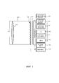
Фиг. 1 является структурной схемой устройства с камерой светового поля в соответствии с вариантом осуществления настоящего изобретения;FIG. 1 is a structural diagram of a light field camera device according to an embodiment of the present invention;
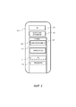
Фиг. 2 является структурной схемой, иллюстрирующей конкретный вариант осуществления потенциально возможной реализации модуля форматирования данных светового поля,FIG. 2 is a block diagram illustrating a specific embodiment of a potentially possible implementation of a light field data formatter,
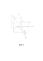
Фиг. 3 иллюстрирует луч света, проходящий через две опорные плоскости P 1 и P 2 , используемые для параметризации,FIG. 3 illustrates a light beam passing through two reference planes P 1 and P 2 used for parameterization,
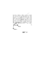
Фиг. 4 иллюстрирует луч света, проходящий через опорную плоскость P 3 , находящуюся на известных глубинах z 3 ,FIG. 4 illustrates a light beam passing through a reference plane P 3 at known depths z 3 ,
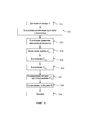
Фиг. 5 является блок-схемой последовательности операций, иллюстрирующей этапы способа для форматирования данных светового поля согласно варианту осуществления настоящего изобретения,FIG. 5 is a flowchart illustrating method steps for formatting light field data according to an embodiment of the present invention,
Фиг. 6 является блок-схемой последовательности операций, иллюстрирующей этапы способа для форматирования данных светового поля согласно варианту осуществления настоящего изобретения,FIG. 6 is a flowchart illustrating method steps for formatting light field data according to an embodiment of the present invention,
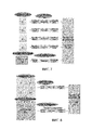
Фиг. 7 представляет карты сопоставления ![]()
![]()
![]()
![]()
![]()
![]()
Фиг. 8 представляет карты сопоставления ![]()
![]()
![]()
![]()
![]()
![]()
ПОДРОБНОЕ ОПИСАНИЕ ИЗОБРЕТЕНИЯDETAILED DESCRIPTION OF THE INVENTION
Как будет понятно специалисту в данной области техники, аспекты настоящих принципов могут быть воплощены в виде системы, способа или машиночитаемой среды. Соответственно, аспекты настоящих принципов могут принимать форму полностью аппаратного варианта осуществления, полностью программного варианта осуществления (включающего в себя встроенное программное обеспечение, резидентное программное обеспечение, набор микрокоманд, и т.д.) или варианта осуществления, сочетающего программные и аппаратные аспекты, которые все в целом могут упоминаться в данном документе как "контур", "модуль" или "система". Кроме того, аспекты настоящих принципов могут принимать форму машиночитаемого носителя данных. Может использоваться любая комбинация одного или нескольких машиночитаемых носителей данных.As will be understood by one of ordinary skill in the art, aspects of the present principles may be embodied in a system, method, or computer readable medium. Accordingly, aspects of the present principles may take the form of an all-hardware embodiment, an all-software embodiment (including firmware, resident software, microinstruction set, etc.), or an embodiment combining software and hardware aspects that are all may generally be referred to herein as a "loop", "module", or "system". In addition, aspects of the present principles may take the form of a computer-readable storage medium. Any combination of one or more computer readable storage media can be used.
Варианты осуществления настоящего изобретения обеспечивают форматирование данных светового поля для приложений дополнительной обработки, таких как преобразование формата, перефокусировка, изменение точки обзора, и т.д. Предлагаемое форматирование дает возможность правильной и легкой реконструкции данных светового поля на принимающей стороне для их обработки. Преимущество предлагаемого формата состоит в том, что он не зависит от устройства, используемого для сбора данных светового поля.Embodiments of the present invention provide formatting of light field data for additional processing applications such as format conversion, refocusing, change of viewpoint, etc. The proposed formatting makes it possible to correctly and easily reconstruct the light field data on the receiving side for their processing. The advantage of the proposed format is that it is independent of the device used to collect the light field data.
Фиг. 1 является структурной схемой устройства с камерой светового поля в соответствии с вариантом осуществления настоящего изобретения. Камера светового поля содержит диафрагму/затвор 102, главную (объективную) линзу 101, массив 110 микролинз и массив фотодатчиков. В некоторых вариантах осуществления камера светового поля включает в себя спуск затвора, который активируется для захвата изображения светового поля объекта или сцены. FIG. 1 is a structural diagram of a light field camera device according to an embodiment of the present invention. The light field camera contains an aperture /
Массив 120 фотодатчиков обеспечивает данные изображения светового поля, которые собраны модулем 140 сбора данных СП, для генерирования формата данных светового поля модулем 150 форматирования данных светового поля и/или для обработки устройством 155 обработки данных светового поля. Данные светового поля могут сохраняться, после сбора и после обработки, в памяти 190 в формате первичных данных, в виде субапертурных изображений или фокальных стеков, или в формате данных светового поля в соответствии с вариантами осуществления настоящего изобретения.The
В проиллюстрированном примере модуль 150 форматирования данных светового поля и устройство 155 обработки данных светового поля размещаются в камере 100 светового поля или интегрируются в нее. В других вариантах осуществления настоящего изобретения модуль 150 форматирования данных светового поля и/или устройство 155 обработки данных светового поля могут быть предусмотрены в отдельном компоненте, внешнем по отношению к камере захвата светового поля. Отдельный компонент может быть локальным или удаленным относительно устройства захвата изображения светового поля. Следует понимать, что любой подходящий проводной или беспроводной протокол может использоваться для передачи данных изображения светового поля на модуль 150 форматирования или устройство 155 обработки данных светового поля; например, устройство обработки данных светового поля может переправлять захваченные данные изображения светового поля и/или другие данные при помощи сети Интернет, сотовой сети передачи данных, сети WiFi, протокола связи Bluetooth®, и/или любого другого подходящего средства.In the illustrated example, the light field
Модуль 150 форматирования данных светового поля выполняется с возможностью генерирования данных, представляющих собранное световое поле, в соответствии с вариантами осуществления настоящего изобретения. Модуль 150 форматирования данных светового поля может быть реализован в программном обеспечении, аппаратном обеспечении или их комбинации.The light field
Устройство 155 обработки данных светового поля выполняется с возможностью работы с первичными данными изображения светового поля, принятыми непосредственно от модуля 140 сбора данных СП, например, чтобы сгенерировать форматированные данные и метаданные в соответствии с вариантами осуществления настоящего изобретения. Могут быть сгенерированы выходные данные, например, такие как неподвижные изображения, 2D видеопотоки, и тому подобное, захваченной сцены. Устройство обработки данных светового поля может быть реализовано в программном обеспечении, аппаратном обеспечении или их комбинации.The light
По меньшей мере, в одном варианте осуществления камера 100 светового поля может также включать в себя пользовательский интерфейс 160 для того, чтобы дать пользователю возможность предоставить пользовательский ввод для операции управления камерой 100 посредством устройства 170 управления. Управление камерой может включать в себя одно или несколько из следующего: управление оптическими параметрами камеры, такими как скорость затвора или, в случае регулируемой камеры светового поля, управление относительным расстоянием между массивом микролинз и фотодатчиком, или относительным расстоянием между объективной линзой и массивом микролинз. В некоторых вариантах осуществления относительные расстояния между оптическими элементами камеры светового поля могут быть отрегулированы вручную. Управление камерой также может включать в себя управление другими параметрами сбора данных светового поля, параметрами форматирования данных светового поля или параметрами обработки светового поля камеры. Пользовательский интерфейс 160 может содержать любое подходящее устройство(а) пользовательского ввода, такое как сенсорный экран, кнопки, клавиатура, координатно-указательное устройство и/или тому подобное. Таким образом, ввод, принятый пользовательским интерфейсом, может использоваться для управления и/или конфигурирования модуля 150 форматирования данных СП для управления форматированием данных, устройства 155 обработки данных СП для управления обработкой собранных данных светового поля и устройства 170 управления для управления камерой 100 светового поля.In at least one embodiment, the light field camera 100 may also include a
Камера светового поля включает в себя источник 180 энергии, такой как одна или несколько сменных или перезаряжаемых батарей. Камера светового поля содержит память 190 для хранения захваченных данных светового поля и/или обработанных данных светового поля или других данных, таких как программное обеспечение для реализации способов согласно вариантам осуществления настоящего изобретения. Память может включать в себя внешнюю и/или внутреннюю память. По меньшей мере, в одном варианте осуществления память может быть предусмотрена в обособленном от камеры 100 устройстве и/или местоположении. В одном варианте осуществления память включает в себя съемное/заменяемое устройство хранения данных, такое как карта памяти.The light field chamber includes a
Камера светового поля может также включать в себя блок 165 отображения (например, ЖК-экран) для просмотра сцен перед камерой до захвата и/или для просмотра ранее захваченных и/или визуализированных изображений. Экран 165 также может использоваться для отображения пользователю одного или более меню или другой информации. Камера светового поля может дополнительно включать в себя один или несколько интерфейсов 195 ввода/вывода, таких как интерфейсы FireWire или Универсальная последовательная шина (USB - Universal Serial Bus), или проводные или беспроводные интерфейсы связи для обмена данными через сеть Интернет, сотовую сеть передачи данных, сеть WiFi, протокол связи Bluetooth®, и/или любое другое подходящее средство. Интерфейс 195 ввода/вывода может использоваться для пересылки данных, таких как репрезентативные данные светового поля, сгенерированные модулем форматирования данных СП в соответствии с вариантами осуществления настоящего изобретения, и данных светового поля, таких как первичные данные светового поля или данные, обработанные устройством 155 обработки данных СП, на внешние устройства, такие как компьютерные системы или блоки отображения, и от них, для приложений визуализации.The light field camera may also include a display unit 165 (eg, an LCD screen) for viewing scenes in front of the camera prior to capturing and / or for viewing previously captured and / or rendered images.
Фиг. 2 является структурной схемой, иллюстрирующей конкретный вариант осуществления потенциально возможной реализации модуля 250 форматирования данных светового поля и устройства 253 обработки данных светового поля. FIG. 2 is a block diagram illustrating a specific embodiment of a potential implementation of the light
Контур 200 включает в себя память 290, устройство 245 управления памятью и схему 240 обработки, содержащую один или несколько блоков обработки (ЦП). Один или несколько блоков 240 обработки выполняются с возможностью запуска различных программ из системы программного обеспечения и/или наборов инструкций, хранящихся в памяти 290, для выполнения различных функций, включающих в себя форматирование данных светового поля и обработку данных светового поля. Компоненты программного обеспечения, хранящиеся в памяти, включают в себя модуль 250 форматирования данных (или набор инструкций) для генерирования данных представляющих собранные световые данные в соответствии с вариантами осуществления настоящего изобретения и модуль 255 обработки данных светового поля (или набор инструкций) для обработки данных светового поля, в соответствии с вариантами осуществления настоящего изобретения. Другие модули могут заключаться в память для приложений устройства с камерой светового поля, такие как модуль 251 операционной системы для управления общими системными задачами (например, регулирование питания, распределение памяти) и для обеспечения связи между различными аппаратными и программными компонентами устройства 200, и интерфейсный модуль 252 для управления и регулирования связи с другими устройствами через порты интерфейса ввода/вывода.
Варианты осуществления настоящего изобретения обеспечивают представление данных светового поля на основе лучей света, воспринимаемых пикселями датчика камеры или моделируемых системой машинно-генерируемых сцен. В действительности, другим источником данных светового поля могут быть произведенные впоследствии данные, которые модифицированы, к примеру, отсортированы по цвету, данные светового поля, полученные из оптического устройства или CGI. В киноиндустрии сейчас также широко распространены данные, которые представляют собой смешение как данных, собранных с использованием оптического устройства сбора, так и данных CGI. Следует понимать, что пиксель датчика может быть смоделирован системой машинно-генерируемых сцен и, если обобщать, весь датчик может быть смоделирован упомянутой системой. Отсюда следует, что любая отсылка к "пикселю датчика" или "датчику" может подразумевать либо физический объект, прикрепленный к оптическому устройству сбора, либо моделируемый элемент, полученный с помощью системы машинно-генерируемых сцен.Embodiments of the present invention provide a representation of light field data based on light beams perceived by camera sensor pixels or system-generated computer generated scenes. In fact, another source of light field data may be subsequently generated data that has been modified, eg, sorted by color, light field data obtained from an optical device, or CGI. There is also widespread data in the film industry today, which is a mixture of both data collected using an optical acquisition device and CGI data. It should be understood that a sensor pixel can be modeled by a system of computer generated scenes and, generally speaking, an entire sensor can be modeled by said system. It follows that any reference to a "sensor pixel" or "sensor" can imply either a physical object attached to an optical acquisition device or a modeled element derived from a computer generated scene system.
Зная что, независимо от типа системы сбора, пикселю датчика упомянутой системы сбора соответствует, по меньшей мере, линейная траектория света, или луч света, в пространстве вне системы сбора, вычисляются данные, представляющие луч света в трехмерном (или 3D) пространстве.Knowing that, regardless of the type of acquisition system, a sensor pixel of said acquisition system corresponds to at least a linear trajectory of light, or a beam of light, in space outside the acquisition system, data representing a light beam in three-dimensional (or 3D) space is calculated.
В первом варианте осуществления, Фиг. 3 иллюстрирует луч света, проходящий через две опорные плоскости P 1 и P 2 , используемые для параметризации, расположенные параллельно друг другу и находящиеся на известных глубинах z 1 и z 2 , соответственно. Луч света пересекает первую опорную плоскость P 1 на глубине z 1 в точке пересечения (x 1 , y 1 ) и пересекает вторую опорную плоскость P 2 на глубине z 2 в точке пересечения (x 2 , y 2 ). Таким образом, с учетом z 1 и z 2 , луч света может быть идентифицирован четырьмя координатами (x 1 , y 1 , x 2 , y 2 ). В силу этого, световое поле может быть параметризовано парой опорных плоскостей для параметризации P 1 , P 2 , также упоминаемых в данном документе как плоскости параметризации, при этом каждый луч света представляется в виде точки ![]()
![]()
Во втором варианте осуществления, представленном на Фиг. 4, луч света параметризуется посредством точки пересечения между опорной плоскостью P 3 , находящейся на известных глубинах z 3 , и лучом света. Луч света пересекает опорную плоскость P 3 на глубине z 3 в точке пересечения (x 3 , y 3 ). Нормализованный вектор ![]()
![]()
![]()
![]()
![]()
![]()
![]()
![]()
![]()
![]()
![]()
![]()
![]()
![]()
Согласно этому второму варианту осуществления, луч света может быть идентифицирован четырьмя координатами ![]()
![]()
![]()
![]()
Параметры, представляющие луч света в 4D пространстве лучей, вычисляются модулем 150 форматирования данных светового поля. Фиг. 5 является блок-схемой последовательности операций, иллюстрирующей этапы способа для форматирования данных светового поля, собранных камерой 100, в соответствии с вариантом осуществления настоящего изобретения. Этот способ исполняется модулем 150 форматирования данных светового поля.Parameters representing a ray of light in 4D ray space are calculated by the light
В случае если система сбора светового поля откалибрована с использованием модели точечной диафрагмы, базовая проекционная модель, без искажений, задается следующим уравнением:If the system for collecting the light field is calibrated using a pinhole model, the basic projection model, without distortion, is given by the following equation:

гдеWhere
![]()
![]()
![]()
![]()
![]()
![]()
![]()
![]()
![]()
![]()
![]()
![]()
На этапе 501 модуль 150 форматирования данных светового поля вычисляет координаты вектора V, представляющего направление луча света в пространстве, который воспринимается пикселем датчика, координаты которого ![]()
![]()
![]()
![]()
В модели точечной диафрагмы координаты пересечения луча света, воспринимаемого пикселем, координаты которого ![]()
![]()
![]()
![]()

и вычисляются в ходе этапа 502.and are calculated during
Если смешивается несколько сборов данных, т.е. при сборе данных светового поля разными типами камер, используется единая система координат. В этой ситуации модификации координат точек и векторов должны быть соответствующим образом изменены.If multiple datasets are mixed, i.e. when collecting light field data by different types of cameras, a single coordinate system is used. In this situation, the modifications of the coordinates of points and vectors must be changed accordingly.
Согласно варианту осуществления настоящего изобретения, наборы координат, определяющих лучи света, воспринимаемые пикселями датчика камеры, и вычисленные в ходе этапов 501 и 502, перегруппируются в карты сопоставления. В другом варианте осуществления лучи света непосредственно вычисляются системой машинно-генерируемых сцен, которая моделирует распространение лучей света.According to an embodiment of the present invention, the sets of coordinates defining the light rays perceived by the camera sensor pixels and calculated in
В варианте осуществления настоящего изобретения эти карты сопоставления соотносятся с цветовой картой данных светового поля, подлежащих передаче на принимающее устройство. Таким образом, в этом варианте осуществления, для каждого пикселя ![]()
![]()
![]()
![]()
![]()
![]()
![]()
![]()
![]()
![]()
![]()
![]()
![]()
![]()
![]()
![]()
![]()
![]()
В другом варианте осуществления система сбора не калибруется с использованием модели точечной диафрагмы, следовательно, параметризация двумя плоскостями не пересчитывается из модели. Вместо этого параметризация двумя плоскостями должна быть экспериментально найдена во время операции калибровки камеры. Это может, к примеру, иметь место для пленоптической камеры, которая включает в себя между главной линзой и датчиком камеры массив микролинз.In another embodiment, the acquisition system is not calibrated using the pinhole model, hence the two-plane parameterization is not recalculated from the model. Instead, the two-plane parameterization must be experimentally found during the camera calibration operation. This may, for example, be the case for a plenoptic camera that includes an array of microlenses between the main lens and the camera sensor.
Еще в одном варианте осуществления эти карты сопоставления непосредственно моделируются системой машинно-генерируемых сцен или производятся впоследствии из собранных данных.In yet another embodiment, these mapping maps are directly modeled by the computer generated scene system or subsequently produced from the collected data.
Поскольку луч света, воспринимаемый пикселем датчика камеры, представляется квадруплетом ![]()
![]()
![]()
![]()
![]()
![]()
![]()
![]()
![]()
![]()
![]()
![]()
После некоторых адаптаций, учитывающих сильную корреляцию между параметрами, представляющими лучи света, воспринимаемые соседними пикселями, и упорядочивания совокупности лучей света, а следовательно, и параметров, которые их представляют, эти четыре карты сопоставления могут быть сжаты с использованием таких же инструментальных средств, как и для видеоданных.After some adaptations, taking into account the strong correlation between the parameters representing the rays of light perceived by neighboring pixels and arranging the set of rays of light, and therefore the parameters that represent them, these four mapping maps can be compressed using the same tools as for video data.
Чтобы сжать значения с плавающими запятыми ![]()
![]()
![]()
![]()
![]()
![]()
![]()
![]()
![]()
![]()
![]()
![]()
![]()
![]()
где u и v являются координатами заданного пикселя датчика камеры.where u and v are the coordinates of the specified pixel of the camera sensor.
На этапе 504, для каждой карты сопоставления ![]()
![]()
![]()
![]()
![]()
![]()
Результатом вычисления на этапе 504 является параметр:The result of the calculation at
![]()
![]()
который соответствует разности значения параметра ![]()
![]()
![]()
![]()
![]()
![]()
Можно сжать значение ![]()
![]()
![]()
![]()
Затем, на этапе 506, может быть вычислено значение ![]()
![]()
![]()
![]()
![]()
![]()
![]()
![]()
![]()
![]()

На этапе 507 модуль 150 форматирования данных светового поля генерирует четыре карты сопоставления, карту сопоставления ![]()
![]()
![]()
![]()
![]()
![]()
![]()
![]()
![]()
![]()
На этапе 508 модуль 150 форматирования данных светового поля генерирует сообщение SEI (информация для дополнительной оптимизации), содержащее следующие фиксированные параметры ![]()
![]()
![]()
![]()
Таблица 1Table 1
![]()
![]()
![]()
![]()
![]()
![]()
![]()
![]()
![]()
![]()
![]()
![]()
![]()
![]()
![]()
![]()
![]()
![]()
![]()
![]()
![]()
![]()
![]()
![]()
![]()
![]()
![]()
![]()
![]()
![]()
![]()
![]()
На стороне принимающего устройства обратное вычисление, позволяющее извлечь исходные карты сопоставления ![]()
![]()
i. 
ii. ![]()
![]()
На этапе 509 карты сопоставления ![]()
![]()
Можно дополнительно уменьшить размер карт сопоставления, представляющих данные светового поля, перед их передачей на принимающее устройство. Следующие варианты осуществления дополняют вариант осуществления, заключающийся в минимизации ошибки:You can further reduce the size of the mapping maps representing the light field data before transmitting it to the receiving device. The following embodiments complement the error minimization embodiment:
![]()
![]()
В первом варианте осуществления, представленном на Фиг. 6, поскольку карты сопоставления ![]()
![]()
Например, при ![]()
![]()
![]()
![]()
![]()
![]()
![]()
![]()
![]()
![]()
![]()
![]()
![]()
![]()
![]()
![]()
В более широком смысле, в ходе этапа 601, модуль 150 форматирования данных светового поля вычисляет разность между значением параметра ![]()
![]()
![]()
![]()
![]()
![]()
Если заданный пиксель является первым пикселем строки датчика, модуль 150 форматирования данных светового поля вычисляет разность между значением параметра ![]()
![]()
![]()
![]()
![]()
![]()
На этапе 602 карты сопоставления ![]()
![]()
Во втором варианте осуществления, поскольку карты сопоставления ![]()
![]()
![]()
![]()
![]()
![]()
![]()
![]()
![]()
![]()
![]()
![]()
К примеру, предположим, что мы можем уменьшить размер карт сопоставления с N_строк*M_столбцов до N_строк/2*M_столбцов/2. При приеме карты сопоставления могут быть расширены до первоначального размера; созданные пропуски могут быть заполнены с помощью способа интерполяции (или так называемого процесса повышающей дискретизации). Обычно достаточно простой билинейной интерполяцииFor example, suppose we can reduce the size of the mapping maps from N_lines * M_columns to N_lines / 2 * M_columns / 2. Upon receipt of the map, the mapping can be expanded to its original size; the created gaps can be filled using an interpolation method (or a so-called upsampling process). Usually simple bilinear interpolation is sufficient
![]()
![]()
В третьем варианте осуществления, представленном на Фиг. 7, каждая карта сопоставления ![]()
![]()
![]()
![]()
![]()
![]()
В четвертом варианте осуществления карты сопоставления ![]()
![]()
![]()
![]()
![]()
![]()
![]()
![]()
![]()
![]()
![]()
![]()
В этом случае сообщение SEI, как представленное в Таблице 1, также должно содержать флаг, указывающий на то, что способ упаковки кадров использовался для упаковки 4 карт сопоставления в одну (см. Таблицу 1b).In this case, the SEI message, as shown in Table 1, shall also contain a flag indicating that the frame packing method was used to pack 4 map cards into one (see Table 1b).
Таблица 1bTable 1b
1: означает упаковку кадров (одна карта сопоставления с 4 квадрантами)0: means no frame packing (separate single mapping cards)
1: means frame packing (one mapping card with 4 quadrants)
![]()
![]()
![]()
![]()
![]()
![]()
![]()
![]()
![]()
![]()
![]()
![]()
![]()
![]()
![]()
![]()
![]()
![]()
![]()
![]()
![]()
![]()
![]()
![]()
![]()
![]()
![]()
![]()
![]()
![]()
![]()
![]()
Когда несколько камер сгруппированы для формирования установки, лучше и более последовательно определить единую внешнюю систему координат и 2 плоскости параметризации, общие для всех камер. Тогда описательное сообщение (SEI, к примеру) может содержать общую информацию (тип представления, z1 и z2) плюс описательные параметры 4 карт сопоставления (карт сопоставления ![]()
![]()
![]()
![]()
![]()
![]()
В этом случае карты сопоставления ![]()
![]()
![]()
![]()
![]()
![]()
Таблица 2table 2
1: означает упаковку кадров (4 квадранта)0: means no frame packing (single mapping card)
1: means frame packing (4 quadrants)
![]()
![]()
![]()
![]()
![]()
![]()
![]()
![]()
![]()
![]()
![]()
![]()
![]()
![]()
![]()
![]()
![]()
![]()
![]()
![]()
![]()
![]()
![]()
![]()
![]()
![]()
![]()
![]()
![]()
![]()
![]()
![]()
В пятом варианте осуществления, когда изменения карт сопоставления ![]()
![]()
![]()
![]()
![]()
![]()
![]()
![]()
![]()
![]()
![]()
![]()
![]()
![]()
![]()
![]()
![]()
![]()
Таблица 3Table 3
1: означает сохранение предыдущих зарегистрированных параметров0: indicates the presence of additional data
1: means keeping the previous registered parameters
1: означает упаковку кадров (4 квадранта)0: means no frame packing (single mapping card)
1: means frame packing (4 quadrants)
![]()
![]()
![]()
![]()
![]()
![]()
![]()
![]()
![]()
![]()
![]()
![]()
![]()
![]()
![]()
![]()
![]()
![]()
![]()
![]()
![]()
![]()
![]()
![]()
![]()
![]()
![]()
![]()
![]()
![]()
![]()
![]()
В шестом варианте осуществления, поскольку модификации параметров системы сбора, представленных в картах сопоставления ![]()
![]()
![]()
![]()
![]()
![]()
![]()
![]()
![]()
![]()
![]()
![]()
В седьмом варианте осуществления цветовые карты используют формат YUV или RGB и кодируются средством кодирования видеоданных, таким как MPEG-4 AVC, h265/HEVC или h266, и т.д., либо средством кодирования изображений, таким как JPEG, JPEG2000, MJEG. Когда используется несколько камер для сбора содержимого светового поля, цветовые карты могут быть закодированы соответственно с использованием средства кодирования-декодирования MV-HEVC.In the seventh embodiment, the color maps use YUV or RGB format and are encoded by a video encoding means such as MPEG-4 AVC, h265 / HEVC or h266, etc., or an image encoding means such as JPEG, JPEG2000, MJEG. When multiple cameras are used to collect the contents of the light field, the color maps can be encoded accordingly using the MV-HEVC codec tool.
Хотя настоящее изобретение и описано выше со ссылкой на конкретные варианты осуществления, настоящее изобретение не ограничивается этими конкретными вариантами осуществления, и для специалиста в данной области техники будут очевидны модификации, которые лежат в пределах объема настоящего изобретения.Although the present invention has been described above with reference to specific embodiments, the present invention is not limited to these specific embodiments, and modifications that fall within the scope of the present invention will be apparent to a person skilled in the art.
Многие дополнительные модификации и вариации будут самостоятельно предложены специалистами в данной области техники при обращении к приведенным выше иллюстративным вариантам осуществления, которые приведены лишь в качестве примера и не предназначены для ограничения объема настоящего изобретения, который устанавливается исключительно прилагаемой формулой изобретения. В частности, разные признаки из разных вариантов осуществления могут быть взаимозаменяемы, когда это целесообразно.Many additional modifications and variations will be independently suggested by those skilled in the art upon reference to the above illustrative embodiments, which are given by way of example only and are not intended to limit the scope of the present invention, which is set solely by the appended claims. In particular, different features from different embodiments may be interchangeable as appropriate.
Claims (18)
Applications Claiming Priority (2)
| Application Number | Priority Date | Filing Date | Title |
|---|---|---|---|
| EP16305757.3 | 2016-06-22 | ||
| EP16305757.3A EP3261347A1 (en) | 2016-06-22 | 2016-06-22 | A method and a device for encoding a signal representative of a light-field content |
Publications (3)
| Publication Number | Publication Date |
|---|---|
| RU2017121569A RU2017121569A (en) | 2018-12-24 |
| RU2017121569A3 RU2017121569A3 (en) | 2020-09-25 |
| RU2746344C2 true RU2746344C2 (en) | 2021-04-12 |
Family
ID=56511475
Family Applications (1)
| Application Number | Title | Priority Date | Filing Date |
|---|---|---|---|
| RU2017121569A RU2746344C2 (en) | 2016-06-22 | 2017-06-20 | Method and the device for encoding a signal representing the content of a light field |
Country Status (10)
| Country | Link |
|---|---|
| US (1) | US11665369B2 (en) |
| EP (3) | EP3261347A1 (en) |
| JP (1) | JP7171169B2 (en) |
| KR (1) | KR102505130B1 (en) |
| CN (1) | CN107529062A (en) |
| AU (1) | AU2017204215C1 (en) |
| BR (1) | BR102017013446A2 (en) |
| CA (1) | CA2971337A1 (en) |
| MX (1) | MX2017008222A (en) |
| RU (1) | RU2746344C2 (en) |
Families Citing this family (3)
| Publication number | Priority date | Publication date | Assignee | Title |
|---|---|---|---|---|
| KR20190052089A (en) * | 2016-09-19 | 2019-05-15 | 인터디지털 브이씨 홀딩스 인코포레이티드 | Method and device for reconfiguring a point cloud representing scene using bright field data |
| CN112183637B (en) * | 2020-09-29 | 2024-04-09 | 中科方寸知微(南京)科技有限公司 | Single-light-source scene illumination re-rendering method and system based on neural network |
| CN116528065B (en) * | 2023-06-30 | 2023-09-26 | 深圳臻像科技有限公司 | Efficient virtual scene content light field acquisition and generation method |
Citations (5)
| Publication number | Priority date | Publication date | Assignee | Title |
|---|---|---|---|---|
| US20080152215A1 (en) * | 2006-12-26 | 2008-06-26 | Kenichi Horie | Coding method, electronic camera, recording medium storing coded program, and decoding method |
| RU2331919C2 (en) * | 2006-03-21 | 2008-08-20 | Алексей Евгеньевич Субботин | Projector encoding |
| US20140003732A1 (en) * | 2012-06-28 | 2014-01-02 | Canon Kabushiki Kaisha | Method and apparatus for compressing or decompressing light field images |
| US20140232822A1 (en) * | 2013-02-21 | 2014-08-21 | Pelican Imaging Corporation | Systems and methods for generating compressed light field representation data using captured light fields, array geometry, and parallax information |
| US20140376826A1 (en) * | 2011-09-28 | 2014-12-25 | Pelican Imaging Corporation | Systems and methods for decoding light field image files having depth and confidence maps |
Family Cites Families (21)
| Publication number | Priority date | Publication date | Assignee | Title |
|---|---|---|---|---|
| US6097394A (en) * | 1997-04-28 | 2000-08-01 | Board Of Trustees, Leland Stanford, Jr. University | Method and system for light field rendering |
| EP1264281A4 (en) * | 2000-02-25 | 2007-07-11 | Univ New York State Res Found | Apparatus and method for volume processing and rendering |
| US6693964B1 (en) * | 2000-03-24 | 2004-02-17 | Microsoft Corporation | Methods and arrangements for compressing image based rendering data using multiple reference frame prediction techniques that support just-in-time rendering of an image |
| US7609906B2 (en) | 2006-04-04 | 2009-10-27 | Mitsubishi Electric Research Laboratories, Inc. | Method and system for acquiring and displaying 3D light fields |
| US7756407B2 (en) | 2006-05-08 | 2010-07-13 | Mitsubishi Electric Research Laboratories, Inc. | Method and apparatus for deblurring images |
| US20100265385A1 (en) * | 2009-04-18 | 2010-10-21 | Knight Timothy J | Light Field Camera Image, File and Configuration Data, and Methods of Using, Storing and Communicating Same |
| US20130113981A1 (en) * | 2006-12-01 | 2013-05-09 | Lytro, Inc. | Light field camera image, file and configuration data, and methods of using, storing and communicating same |
| US8229294B2 (en) * | 2007-12-10 | 2012-07-24 | Mitsubishi Electric Research Laboratories, Inc. | Cameras with varying spatio-angular-temporal resolutions |
| US8749620B1 (en) * | 2010-02-20 | 2014-06-10 | Lytro, Inc. | 3D light field cameras, images and files, and methods of using, operating, processing and viewing same |
| CN103748612B (en) * | 2011-01-24 | 2018-04-27 | 英特尔公司 | For obtaining, representing, comparing and transmitting the method and system of three-dimensional data |
| EP2835969A4 (en) * | 2012-04-06 | 2015-09-09 | Sony Corp | Decoding apparatus, decoding method, encoding apparatus and encoding method |
| US9179126B2 (en) * | 2012-06-01 | 2015-11-03 | Ostendo Technologies, Inc. | Spatio-temporal light field cameras |
| WO2014009603A1 (en) * | 2012-07-02 | 2014-01-16 | Nokia Corporation | Method and apparatus for video coding |
| US9743064B2 (en) * | 2012-09-11 | 2017-08-22 | The Directv Group, Inc. | System and method for distributing high-quality 3D video in a 2D format |
| JP2014086968A (en) | 2012-10-25 | 2014-05-12 | Ricoh Co Ltd | Image processing device, image processing method, and program |
| US9582922B2 (en) * | 2013-05-17 | 2017-02-28 | Nvidia Corporation | System, method, and computer program product to produce images for a near-eye light field display |
| US9264661B2 (en) * | 2013-06-07 | 2016-02-16 | Apple Inc. | Adaptive post-processing for mobile video calling system |
| KR102156402B1 (en) * | 2013-11-05 | 2020-09-16 | 삼성전자주식회사 | Method and apparatus for image processing |
| US9414087B2 (en) | 2014-04-24 | 2016-08-09 | Lytro, Inc. | Compression of light field images |
| US9712820B2 (en) * | 2014-04-24 | 2017-07-18 | Lytro, Inc. | Predictive light field compression |
| US9961333B1 (en) * | 2016-06-10 | 2018-05-01 | X Development Llc | System and method for light field projection |
-
2016
- 2016-06-22 EP EP16305757.3A patent/EP3261347A1/en not_active Withdrawn
-
2017
- 2017-06-16 EP EP22163305.0A patent/EP4054194A1/en active Pending
- 2017-06-16 EP EP17176402.0A patent/EP3261348A1/en not_active Ceased
- 2017-06-20 MX MX2017008222A patent/MX2017008222A/en unknown
- 2017-06-20 CA CA2971337A patent/CA2971337A1/en active Pending
- 2017-06-20 JP JP2017120128A patent/JP7171169B2/en active Active
- 2017-06-20 RU RU2017121569A patent/RU2746344C2/en active
- 2017-06-21 AU AU2017204215A patent/AU2017204215C1/en active Active
- 2017-06-21 BR BR102017013446-6A patent/BR102017013446A2/en unknown
- 2017-06-22 US US15/629,951 patent/US11665369B2/en active Active
- 2017-06-22 KR KR1020170079028A patent/KR102505130B1/en active IP Right Grant
- 2017-06-22 CN CN201710481124.XA patent/CN107529062A/en active Pending
Patent Citations (5)
| Publication number | Priority date | Publication date | Assignee | Title |
|---|---|---|---|---|
| RU2331919C2 (en) * | 2006-03-21 | 2008-08-20 | Алексей Евгеньевич Субботин | Projector encoding |
| US20080152215A1 (en) * | 2006-12-26 | 2008-06-26 | Kenichi Horie | Coding method, electronic camera, recording medium storing coded program, and decoding method |
| US20140376826A1 (en) * | 2011-09-28 | 2014-12-25 | Pelican Imaging Corporation | Systems and methods for decoding light field image files having depth and confidence maps |
| US20140003732A1 (en) * | 2012-06-28 | 2014-01-02 | Canon Kabushiki Kaisha | Method and apparatus for compressing or decompressing light field images |
| US20140232822A1 (en) * | 2013-02-21 | 2014-08-21 | Pelican Imaging Corporation | Systems and methods for generating compressed light field representation data using captured light fields, array geometry, and parallax information |
Also Published As
| Publication number | Publication date |
|---|---|
| BR102017013446A2 (en) | 2018-05-02 |
| AU2017204215B2 (en) | 2022-04-28 |
| CN107529062A (en) | 2017-12-29 |
| AU2017204215A1 (en) | 2018-01-18 |
| KR20180000319A (en) | 2018-01-02 |
| EP3261347A1 (en) | 2017-12-27 |
| CA2971337A1 (en) | 2017-12-22 |
| US11665369B2 (en) | 2023-05-30 |
| RU2017121569A (en) | 2018-12-24 |
| US20170374388A1 (en) | 2017-12-28 |
| EP4054194A1 (en) | 2022-09-07 |
| RU2017121569A3 (en) | 2020-09-25 |
| EP3261348A1 (en) | 2017-12-27 |
| JP7171169B2 (en) | 2022-11-15 |
| JP2018033127A (en) | 2018-03-01 |
| KR102505130B1 (en) | 2023-03-02 |
| MX2017008222A (en) | 2018-09-10 |
| AU2017204215C1 (en) | 2023-02-02 |
Similar Documents
| Publication | Publication Date | Title |
|---|---|---|
| US20190387211A1 (en) | A method and a device for reconstructing a point cloud representative of a scene using light-field data | |
| CN101416520B (en) | Efficient encoding of multiple views | |
| CN106131531B (en) | Method for processing video frequency and device | |
| EP2922021A1 (en) | Method, apparatus and computer program product for filtering of media content | |
| RU2746344C2 (en) | Method and the device for encoding a signal representing the content of a light field | |
| GB2503656A (en) | Compressing and decompressing plenoptic images | |
| US20190158877A1 (en) | Method and apparatus for encoding and decoding a light field based image, and corresponding computer program product | |
| EP3301926A1 (en) | A method and a device for reconstructing a point cloud representative of a scene using light-field data | |
| CN112714302B (en) | Naked eye 3D image manufacturing method and device | |
| US11948268B2 (en) | Immersive video bitstream processing | |
| EP2839437B1 (en) | View synthesis using low resolution depth maps | |
| Li et al. | Joint view filtering for multiview depth map sequences | |
| Kukolj et al. | 3D content acquisition and coding | |
| JP7382186B2 (en) | Encoding device, decoding device, and program | |
| JP7417388B2 (en) | Encoding device, decoding device, and program | |
| WO2022193875A1 (en) | Method and apparatus for processing multi-viewing-angle video, and device and storage medium | |
| EP3203742A1 (en) | System and method for encoding and decoding information representative of a focalization distance associated to an image belonging to a focal stack representative of a light field content | |
| CN115104121A (en) | Method and apparatus for processing image content | |
| Xiang et al. | Depth error induced virtual view synthesis distortion estimation for 3D video coding | |
| Pahalawatta et al. | Depth/Disparity Interchange Representation for Post-Production |
Legal Events
| Date | Code | Title | Description |
|---|---|---|---|
| HZ9A | Changing address for correspondence with an applicant |