EP3261347A1 - A method and a device for encoding a signal representative of a light-field content - Google Patents
A method and a device for encoding a signal representative of a light-field content Download PDFInfo
- Publication number
- EP3261347A1 EP3261347A1 EP16305757.3A EP16305757A EP3261347A1 EP 3261347 A1 EP3261347 A1 EP 3261347A1 EP 16305757 A EP16305757 A EP 16305757A EP 3261347 A1 EP3261347 A1 EP 3261347A1
- Authority
- EP
- European Patent Office
- Prior art keywords
- light
- parameters
- pixel
- ray
- field content
- Prior art date
- Legal status (The legal status is an assumption and is not a legal conclusion. Google has not performed a legal analysis and makes no representation as to the accuracy of the status listed.)
- Withdrawn
Links
Images


Classifications
-
- H—ELECTRICITY
- H04—ELECTRIC COMMUNICATION TECHNIQUE
- H04N—PICTORIAL COMMUNICATION, e.g. TELEVISION
- H04N19/00—Methods or arrangements for coding, decoding, compressing or decompressing digital video signals
- H04N19/10—Methods or arrangements for coding, decoding, compressing or decompressing digital video signals using adaptive coding
- H04N19/169—Methods or arrangements for coding, decoding, compressing or decompressing digital video signals using adaptive coding characterised by the coding unit, i.e. the structural portion or semantic portion of the video signal being the object or the subject of the adaptive coding
- H04N19/17—Methods or arrangements for coding, decoding, compressing or decompressing digital video signals using adaptive coding characterised by the coding unit, i.e. the structural portion or semantic portion of the video signal being the object or the subject of the adaptive coding the unit being an image region, e.g. an object
- H04N19/172—Methods or arrangements for coding, decoding, compressing or decompressing digital video signals using adaptive coding characterised by the coding unit, i.e. the structural portion or semantic portion of the video signal being the object or the subject of the adaptive coding the unit being an image region, e.g. an object the region being a picture, frame or field
-
- G—PHYSICS
- G06—COMPUTING; CALCULATING OR COUNTING
- G06T—IMAGE DATA PROCESSING OR GENERATION, IN GENERAL
- G06T7/00—Image analysis
- G06T7/50—Depth or shape recovery
- G06T7/55—Depth or shape recovery from multiple images
- G06T7/557—Depth or shape recovery from multiple images from light fields, e.g. from plenoptic cameras
-
- H—ELECTRICITY
- H04—ELECTRIC COMMUNICATION TECHNIQUE
- H04N—PICTORIAL COMMUNICATION, e.g. TELEVISION
- H04N21/00—Selective content distribution, e.g. interactive television or video on demand [VOD]
- H04N21/20—Servers specifically adapted for the distribution of content, e.g. VOD servers; Operations thereof
- H04N21/23—Processing of content or additional data; Elementary server operations; Server middleware
- H04N21/235—Processing of additional data, e.g. scrambling of additional data or processing content descriptors
- H04N21/2353—Processing of additional data, e.g. scrambling of additional data or processing content descriptors specifically adapted to content descriptors, e.g. coding, compressing or processing of metadata
-
- G—PHYSICS
- G06—COMPUTING; CALCULATING OR COUNTING
- G06T—IMAGE DATA PROCESSING OR GENERATION, IN GENERAL
- G06T9/00—Image coding
- G06T9/20—Contour coding, e.g. using detection of edges
-
- H—ELECTRICITY
- H04—ELECTRIC COMMUNICATION TECHNIQUE
- H04N—PICTORIAL COMMUNICATION, e.g. TELEVISION
- H04N19/00—Methods or arrangements for coding, decoding, compressing or decompressing digital video signals
- H04N19/10—Methods or arrangements for coding, decoding, compressing or decompressing digital video signals using adaptive coding
- H04N19/102—Methods or arrangements for coding, decoding, compressing or decompressing digital video signals using adaptive coding characterised by the element, parameter or selection affected or controlled by the adaptive coding
- H04N19/132—Sampling, masking or truncation of coding units, e.g. adaptive resampling, frame skipping, frame interpolation or high-frequency transform coefficient masking
-
- H—ELECTRICITY
- H04—ELECTRIC COMMUNICATION TECHNIQUE
- H04N—PICTORIAL COMMUNICATION, e.g. TELEVISION
- H04N19/00—Methods or arrangements for coding, decoding, compressing or decompressing digital video signals
- H04N19/10—Methods or arrangements for coding, decoding, compressing or decompressing digital video signals using adaptive coding
- H04N19/134—Methods or arrangements for coding, decoding, compressing or decompressing digital video signals using adaptive coding characterised by the element, parameter or criterion affecting or controlling the adaptive coding
- H04N19/167—Position within a video image, e.g. region of interest [ROI]
-
- H—ELECTRICITY
- H04—ELECTRIC COMMUNICATION TECHNIQUE
- H04N—PICTORIAL COMMUNICATION, e.g. TELEVISION
- H04N19/00—Methods or arrangements for coding, decoding, compressing or decompressing digital video signals
- H04N19/10—Methods or arrangements for coding, decoding, compressing or decompressing digital video signals using adaptive coding
- H04N19/169—Methods or arrangements for coding, decoding, compressing or decompressing digital video signals using adaptive coding characterised by the coding unit, i.e. the structural portion or semantic portion of the video signal being the object or the subject of the adaptive coding
- H04N19/186—Methods or arrangements for coding, decoding, compressing or decompressing digital video signals using adaptive coding characterised by the coding unit, i.e. the structural portion or semantic portion of the video signal being the object or the subject of the adaptive coding the unit being a colour or a chrominance component
-
- H—ELECTRICITY
- H04—ELECTRIC COMMUNICATION TECHNIQUE
- H04N—PICTORIAL COMMUNICATION, e.g. TELEVISION
- H04N19/00—Methods or arrangements for coding, decoding, compressing or decompressing digital video signals
- H04N19/44—Decoders specially adapted therefor, e.g. video decoders which are asymmetric with respect to the encoder
-
- H—ELECTRICITY
- H04—ELECTRIC COMMUNICATION TECHNIQUE
- H04N—PICTORIAL COMMUNICATION, e.g. TELEVISION
- H04N19/00—Methods or arrangements for coding, decoding, compressing or decompressing digital video signals
- H04N19/46—Embedding additional information in the video signal during the compression process
- H04N19/463—Embedding additional information in the video signal during the compression process by compressing encoding parameters before transmission
-
- H—ELECTRICITY
- H04—ELECTRIC COMMUNICATION TECHNIQUE
- H04N—PICTORIAL COMMUNICATION, e.g. TELEVISION
- H04N19/00—Methods or arrangements for coding, decoding, compressing or decompressing digital video signals
- H04N19/50—Methods or arrangements for coding, decoding, compressing or decompressing digital video signals using predictive coding
- H04N19/59—Methods or arrangements for coding, decoding, compressing or decompressing digital video signals using predictive coding involving spatial sub-sampling or interpolation, e.g. alteration of picture size or resolution
-
- H—ELECTRICITY
- H04—ELECTRIC COMMUNICATION TECHNIQUE
- H04N—PICTORIAL COMMUNICATION, e.g. TELEVISION
- H04N19/00—Methods or arrangements for coding, decoding, compressing or decompressing digital video signals
- H04N19/50—Methods or arrangements for coding, decoding, compressing or decompressing digital video signals using predictive coding
- H04N19/593—Methods or arrangements for coding, decoding, compressing or decompressing digital video signals using predictive coding involving spatial prediction techniques
-
- H—ELECTRICITY
- H04—ELECTRIC COMMUNICATION TECHNIQUE
- H04N—PICTORIAL COMMUNICATION, e.g. TELEVISION
- H04N19/00—Methods or arrangements for coding, decoding, compressing or decompressing digital video signals
- H04N19/50—Methods or arrangements for coding, decoding, compressing or decompressing digital video signals using predictive coding
- H04N19/597—Methods or arrangements for coding, decoding, compressing or decompressing digital video signals using predictive coding specially adapted for multi-view video sequence encoding
-
- H—ELECTRICITY
- H04—ELECTRIC COMMUNICATION TECHNIQUE
- H04N—PICTORIAL COMMUNICATION, e.g. TELEVISION
- H04N19/00—Methods or arrangements for coding, decoding, compressing or decompressing digital video signals
- H04N19/70—Methods or arrangements for coding, decoding, compressing or decompressing digital video signals characterised by syntax aspects related to video coding, e.g. related to compression standards
-
- H—ELECTRICITY
- H04—ELECTRIC COMMUNICATION TECHNIQUE
- H04N—PICTORIAL COMMUNICATION, e.g. TELEVISION
- H04N19/00—Methods or arrangements for coding, decoding, compressing or decompressing digital video signals
- H04N19/85—Methods or arrangements for coding, decoding, compressing or decompressing digital video signals using pre-processing or post-processing specially adapted for video compression
-
- H—ELECTRICITY
- H04—ELECTRIC COMMUNICATION TECHNIQUE
- H04N—PICTORIAL COMMUNICATION, e.g. TELEVISION
- H04N21/00—Selective content distribution, e.g. interactive television or video on demand [VOD]
- H04N21/20—Servers specifically adapted for the distribution of content, e.g. VOD servers; Operations thereof
- H04N21/23—Processing of content or additional data; Elementary server operations; Server middleware
- H04N21/234—Processing of video elementary streams, e.g. splicing of video streams, manipulating MPEG-4 scene graphs
- H04N21/2343—Processing of video elementary streams, e.g. splicing of video streams, manipulating MPEG-4 scene graphs involving reformatting operations of video signals for distribution or compliance with end-user requests or end-user device requirements
-
- H—ELECTRICITY
- H04—ELECTRIC COMMUNICATION TECHNIQUE
- H04N—PICTORIAL COMMUNICATION, e.g. TELEVISION
- H04N21/00—Selective content distribution, e.g. interactive television or video on demand [VOD]
- H04N21/20—Servers specifically adapted for the distribution of content, e.g. VOD servers; Operations thereof
- H04N21/23—Processing of content or additional data; Elementary server operations; Server middleware
- H04N21/235—Processing of additional data, e.g. scrambling of additional data or processing content descriptors
- H04N21/2355—Processing of additional data, e.g. scrambling of additional data or processing content descriptors involving reformatting operations of additional data, e.g. HTML pages
Definitions
- the present invention relates to the transmission of sets of data and metadata and more particularly to the transmission of light-field contents.
- 4D light-field data Compared to classical two-dimensional or 2D images obtained from a camera, 4D light-field data enable a user to have access to more post-processing features that enhance the rendering of images and the interactivity with the user. For example, with 4D light-field data, it is possible to perform refocusing of images with freely selected distances of focalization meaning that the position of a focal plane can be specified/selected a posteriori, as well as changing slightly the point of view in the scene of an image.
- 4D light-field data can be represented, when recorded by a plenoptic camera by a collection of microlens images. 4D light-field data in this representation are named raw images or raw 4D light-field data. Secondly, 4D light-field data can be represented, either when recorded by a plenoptic camera or by a camera array, by a set of sub-aperture images.
- a sub-aperture image corresponds to a captured image of a scene from a point of view, the point of view being slightly different between two sub-aperture images. These sub-aperture images give information about the parallax and depth of the imaged scene.
- 4D light-field data can be represented by a set ot epipolar images see for example the article entitled : " Generating EPI Representation of a 4D Light Fields with a Single Lens Focused Plenoptic Camera", by S. Wanner and al., published in the conference proceedings ot ISVC 2011 .
- Light-field data take up large amounts of storage space which makes storage cumbersome and processing less efficient.
- light-field acquisition devices are extremely heterogeneous.
- Light-field cameras are of different types for example plenoptic or camera arrays. Within each type there are many differences such as different optical arrangements, or micro-lenses of different focal lengths. Each camera has its own proprietary file format. At present there is no standard supporting the acquisition and transmission of multi-dimensional information for an exhaustive over-view of the different parameters upon which a light-field depends. Since acquired light-field data from different cameras have a diversity of formats a complex processing is induced on the receiver side.
- the parameters transmitted according to the encoding method according to an embodiment of the invention are independent of the optical acquisition system used to acquire the light-field content intended to be transmitted and processed by a receiving device.
- the parameters representing the rays of light sensed by the different pixels of the sensor of the optical acquisition system i.e. the parameters of the first set of parameters
- these parameters can be considered as pictures.
- the parameters representing the rays of light sensed by the pixels of the sensor of the optical acquisition system are grouped in four pictures.
- Such pictures can be encoded and transmitted according to video standards such as MPEG-4 part 10 AVC (also called h264), h265/HEVC or their probable successor h266, and transmitted in a joined video bitstream.
- the second encoded set may be encoded using Supplemental enhancement information (SEI) messages.
- SEI Supplemental enhancement information
- the format defined in the method according to an embodiment of the invention enables a strong compression of the data to be transmitted without introducing any strong error (lossless coding) or a limited amount of errors (lossy coding).
- the method according to an embodiment of the invention is not limited to light-field data directly acquired by an optical device.
- These data may be Computer Graphics Image (CGI) that are totally or partially simulated by a computer for a given scene description.
- CGI Computer Graphics Image
- Another source of light-field data may be post-produced data that are modified, for instance color graded, light-field data obtained from an optical device or CGI.
- CGI data It is also now common in the movie industry to have data that are a mix of both data acquired using an optical acquisition device, and CGI data.
- the pixel of a sensor can be simulated by a computer-generated scene system and, by extension, the whole sensor can be simulated by said system. From here, it is understood that any reference to a "pixel of a sensor" or a "sensor” can be either a physical object attached to an optical acquisition device or a simulated entity obtained by a computer-generated scene system.
- said encoding method further comprises:
- At least one parameter of the first set of parameters represents a distance between a coordinate of said ray of light and a plane fitting a set of coordinates of a plurality of rays of light sensed by a plurality of pixels of the optical acquisition system
- at least one parameter of the second set of parameters represents coordinates of the fitting plane
- Encoding the distance between a coordinate of the ray of light and a plane fitting a set of coordinates of a plurality of rays of light sensed by the different pixels of the sensor enables compressing the data to be transmitted since the amplitude between the different values of the computed distances is usually lower than the amplitude between the different values of the coordinates.
- At least one parameter of the first set of parameters represents:
- the value representing the ray of light could be either the coordinates representing the ray of light or the distance between the coordinates or planes fitting sets of coordinates of a plurality of rays of light sensed by the different pixels of the sensor.
- independent codecs are used to encode the parameters of the first set of parameters.
- the second set of parameters comprises a parameter indicating that the first set of parameters is unchanged since a last transmission of the first set of parameters, only said second set of parameters is transmitted.
- the light-field data is made of a sequence of subsets of light-field data.
- the sub-sets are indexed temporally in order to represent a dynamic or moving scene.
- an element (or sub-set) of the sequence is called a frame.
- the transmission rate usually characterized by, but no limited to, a number of frames per second, of the signal representative of the light-content is higher than the transmission rate of the encoded first set of parameters and the encoded second set of parameters.
- said encoding method further comprises:
- Another aspect of the invention concerns a signal transmitted by a device for encoding a signal representative of a light-field content to a device for decoding said signal representative of a light-field content, said signal carrying a message comprising:
- elements of the invention may be computer implemented. Accordingly, such elements may take the form of an entirely hardware embodiment, an entirely software embodiment (including firmware, resident software, micro-code, etc.) or an embodiment combining software and hardware aspects that may all generally be referred to herein as a "circuit", "module” or “system'. Furthermore, such elements may take the form of a computer program product embodied in any tangible medium of expression having computer usable program code embodied in the medium.
- a tangible carrier medium may comprise a storage medium such as a floppy disk, a CD-ROM, a hard disk drive, a magnetic tape device or a solid state memory device and the like.
- a transient carrier medium may include a signal such as an electrical signal, an electronic signal, an optical signal, an acoustic signal, a magnetic signal or an electromagnetic signal, e.g. a microwave or RF signal.
- aspects of the present principles can be embodied as a system, method or computer readable medium. Accordingly, aspects of the present principles can take the form of an entirely hardware embodiment, an entirely software embodiment, (including firmware, resident software, micro-code, and so forth) or an embodiment combining software and hardware aspects that can all generally be referred to herein as a "circuit", "module”, or “system”. Furthermore, aspects of the present principles can take the form of a computer readable storage medium. Any combination of one or more computer readable storage medium(a) may be utilized.
- Embodiments of the invention provide formatting of light-field data for further processing applications such as format conversion, refocusing, viewpoint change, etc.
- the provided formatting enables a proper and easy reconstruction of the light-field data on the receiver side in order to process it.
- An advantage of the provided format is that it is agnostic to the device used to acquire the light-field data.
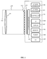
- FIG. 1 is a block diagram of a light-field camera device in accordance with an embodiment of the invention.
- the light-field camera comprises an aperture/shutter 102, a main (objective) lens 101, a micro lens array 110 and a photosensor array.
- the light-field camera includes a shutter release that is activated to capture a light-field image of a subject or scene.
- the photosensor array 120 provides light-field image data which is acquired by LF Data acquisition module 140 for generation of a light-field data format by light-field data formatting module 150 and/or for processing by light-field data processor 155.
- Light-field data may be stored, after acquisition and after processing, in memory 190 in a raw data format, as sub aperture images or focal stacks, or in a light-field data format in accordance with embodiments of the invention.
- the light-field data formatting module 150 and the light-field data processor 155 are disposed in or integrated into the light-field camera 100.
- the light-field data formatting module 150 and/or the light-field data processor 155 may be provided in a separate component external to the light-field capture camera. The separate component may be local or remote with respect to the light-field image capture device.
- any suitable wired or wireless protocol may be used for transmitting light-field image data to the formatting module 150 or light-field data processor 155; for example the light-field data processor may transfer captured light-field image data and/ or other data via the Internet, a cellular data network, a WiFi network, a Bluetooth®) communication protocol, and/ or any other suitable means.
- the light-field data formatting module 150 is configured to generate data representative of the acquired light-field, in accordance with embodiments of the invention.
- the light-field data formatting module 150 may be implemented in software, hardware or a combination thereof.
- the light-field data processor 155 is configured to operate on raw light-field image data received directly from the LF data acquisition module 140 for example to generate formatted data and metadata in accordance with embodiments of the invention. Output data, such as, for example, still images, 2D video streams, and the like of the captured scene may be generated.
- the light-field data processor may be implemented in software, hardware or a combination thereof.
- the light-field camera 100 may also include a user interface 160 for enabling a user to provide user input to control operation of camera 100 by controller 170.
- Control of the camera may include one or more of control of optical parameters of the camera such as shutter speed, or in the case of an adjustable light-field camera, control of the relative distance between the microlens array and the photosensor, or the relative distance between the objective lens and the microlens array. In some embodiments the relative distances between optical elements of the light-field camera may be manually adjusted. Control of the camera may also include control of other light-field data acquisition parameters, light-field data formatting parameters or light-field processing parameters of the camera.
- the user interface 160 may comprise any suitable user input device(s) such as a touchscreen, buttons, keyboard, pointing device, and/ or the like. In this way, input received by the user interface can be used to control and/ or configure the LF data formatting module 150 for controlling the data formatting, the LF data processor 155 for controlling the processing of the acquired light-field data and controller 170 for controlling the light-field camera 100.
- the light-field camera includes a power source 180, such as one or more replaceable or rechargeable batteries.
- the light-field camera comprises memory 190 for storing captured light-field data and/or processed light-field data or other data such as software for implementing methods of embodiments of the invention.
- the memory can include external and/ or internal memory. In at least one embodiment, the memory can be provided at a separate device and/ or location from camera 100. In one embodiment, the memory includes a removable/swappable storage device such as a memory stick.
- the light-field camera may also include a display unit 165 (e.g., an LCD screen) for viewing scenes in front of the camera prior to capture and/or for viewing previously captured and/or rendered images.
- the screen 165 may also be used to display one or more menus or other information to the user.
- the light-field camera may further include one or more I/O interfaces 195, such as FireWire or Universal Serial Bus (USB) interfaces, or wired or wireless communication interfaces for data communication via the Internet, a cellular data network, a WiFi network, a Bluetooth®) communication protocol, and/ or any other suitable means.
- I/O interfaces 195 such as FireWire or Universal Serial Bus (USB) interfaces, or wired or wireless communication interfaces for data communication via the Internet, a cellular data network, a WiFi network, a Bluetooth®) communication protocol, and/ or any other suitable means.
- the I/O interface 195 may be used for transferring data, such as light-field representative data generated by LF data formatting module in accordance with embodiments of the invention and light-field data such as raw light-field data or data processed by LF data processor 155, to and from external devices such as computer systems or display units, for rendering applications.
- data such as light-field representative data generated by LF data formatting module in accordance with embodiments of the invention and light-field data such as raw light-field data or data processed by LF data processor 155, to and from external devices such as computer systems or display units, for rendering applications.
- Figure 2 is a block diagram illustrating a particular embodiment of a potential implementation of light-field data formatting module 250 and the light-field data processor 253.
- the circuit 200 includes memory 290, a memory controller 245 and processing circuitry 240 comprising one or more processing units (CPU(s)).
- the one or more processing units 240 are configured to run various software programs and/or sets of instructions stored in the memory 290 to perform various functions including light-field data formatting and light-field data processing.
- Software components stored in the memory include a data formatting module (or set of instructions) 250 for generating data representative of acquired light data in accordance with embodiments of the invention and a light-field data processing module (or set of instructions) 255 for processing light-field data in accordance with embodiments of the invention.
- Other modules may be included in the memory for applications of the light-field camera device such as an operating system module 251 for controlling general system tasks (e.g. power management, memory management) and for facilitating communication between the various hardware and software components of the device 200, and an interface module 252 for controlling and managing communication with other devices via I/O interface ports.
- Embodiments of the invention provide a representation of light-field data based on rays of light sensed by the pixels of the sensor of a camera or simulated by a computer-generated scene system.
- another source of light-field data may be post-produced data that are modified, for instance color graded, light-field data obtained from an optical device or CGI.
- CGI color graded, light-field data obtained from an optical device
- the pixel of a sensor can be simulated by a computer-generated scene system and, by extension, the whole sensor can be simulated by said system. From here, it is understood that any reference to a "pixel of a sensor" or a "sensor” can be either a physical object attached to an optical acquisition device or a simulated entity obtained by a computer-generated scene system.
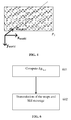
- Figure 3 illustrates a ray of light passing through two reference planes P 1 and P 2 used for parameterization positioned parallel to one another and located at known depths z 1 and z 2 respectively.
- the ray of light intersects the first reference plane P 1 at depth z 1 at intersection point ( x 1 , y 1 ) and intersects the second reference plane P 2 at depth z 2 at intersection point ( x 2 , y 2 ).
- the ray of light can be identified by four coordinates ( x 1 , y 1 , x 2 , y 2 ).
- the light-field can thus be parameterized by a pair of reference planes for parameterization P 1 , P 2 also referred herein as parametrization planes, with each ray of light being represented as a point ( x 1 , y 1 , x 2 , y 2 ,) ⁇ R 4 in 4D ray space.
- the ray of light is parametrized by means a point of intersection between a reference plane P 3 located at known depths z 3 and the ray of light.
- the ray of light intersects the reference plane P 3 at depth z 3 at intersection point ( x 3 , y 3 ).
- the ray of light may be identified by four coordinates ( x 3 , y 3 , v x , v y ).
- the light-field can thus be parameterized by a reference plane for parameterization P 3 also referred herein as parametrization plane, with each ray of light being represented as a point ( x 3 , y 3 , v x , v y ) ⁇ R 4 in 4D ray space.
- FIG. 5 is a flow chart illustrating the steps of a method for formatting the light-field data acquired by the camera 100 according to an embodiment of the invention. This method is executed by the light-field data formatting module 150.
- the light-field data formatting module 150 computes the coordinates of a vector V representing the direction of the ray of light in space that is sensed by the pixel of the sensor which coordinates are ( u , v, 1) T in the sensor coordinate system.
- the coordinates of vector V are: u ⁇ c u , v ⁇ c v , f T .
- the coordinates of the intersection of the ray of light sensed by the pixel which coordinates are ( u , v, 1) T , with a plane placed at coordinate Z 1 from the pinhole and parallel to the sensor plane are: u ⁇ c u Z 1 f , v ⁇ c v Z 1 f , Z 1 T and are computed during a step 502.
- the sets of coordinates defining the rays of light sensed by the pixels of the sensor of the camera and computed during steps 501 and 502 are regrouped in maps.
- the rays of light are directly computed by a computer-generated scene system that simulates the propagation of rays of light.
- these maps are associated with a color map of the light-field data to be transmitted to a receiver.
- parameter representative of the color data associated to a ray of light sensed by a given pixel and a quadruplet of floating point values ( ⁇ 1 ⁇ 2 ⁇ 3 ⁇ 4 ) which correspond either to ( x 1 , y 1 , x 2 , y 2 ) when light-field can thus be parameterized by a pair of reference planes for parameterization P 1 , P 2 or ( x 3 , y 3 , v x , v y ,) when the ray of light is parametrized by means of a normalized vector.
- the acquisition system is not calibrated using a pinhole model, consequently the parametrization by two planes is not recalculated from a model. Instead, the parametrization by two planes has to be measured during a calibration operation of the camera. This may be for instance the case for a plenoptic camera which includes in between the main lens and the sensor of the camera a micro-lens array.
- these maps are directly simulated by a computer-generated scene system or post-produced from acquired data.
- ⁇ 1 ⁇ 2 ⁇ 3 ⁇ 4 a quadruplet ( ⁇ 1 ⁇ 2 ⁇ 3 ⁇ 4 ) of floating point. It is possible to put these four parameters into four maps of parameters, e.g. a first map comprising the parameter ⁇ 1 of each ray of light sensed by a pixel of the sensor of the camera, a second map comprising the parameter ⁇ 2 , a third map comprising the parameter ⁇ 3 and a fourth map comprising the parameter ⁇ 4 .
- Each of the four above-mentioned maps, called ⁇ i maps have the same size as the acquired light-field image itself but have floating points content.
- these four maps can be compressed using similar tools as for video data.
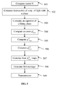
- the light-field data formatting module 150 computes, in a step 503, for each ⁇ i maps an equation of a plane fitting the values of said parameter ⁇ i comprised in the ⁇ i map.
- a step 504 for each ⁇ i map, parameters ⁇ i , ⁇ i , ⁇ i are computed to minimize the error: ⁇ ⁇ i u v ⁇ ⁇ i u ⁇ ⁇ i v ⁇ ⁇ i ⁇
- a value ⁇ i u , v ⁇ of former parameter ⁇ i may be computed so that the value of parameter ⁇ i u , v ⁇ range from 0 to 2 N - 1 included, where N is a chosen number of bits corresponding to the capacity of the encoder intend to used for encoding the light-field data to be sent.
- the light-field data formatting module 150 generates four maps, ⁇ 1 u , v ⁇ map, ⁇ 2 u , v ⁇ map, ⁇ 3 u , v ⁇ map and ⁇ 4 u , v ⁇ map, corresponding to each of the parameters ( ⁇ 1 ⁇ 2 ⁇ 3 ⁇ 4 ) representing rays of light sensed by the pixels of the sensor of the camera.
- the light-field data formatting module 150 generates a SEI (Supplemental Enhancement Information) message comprising the following fixed parameters ⁇ i , ⁇ i , ⁇ i + min ⁇ i i , v ′ , max ⁇ i u , v ′ ′ intended to be used during reciprocal computation on the receiver side to retrieve the original ⁇ i u,v maps.
- SEI Supplemental Enhancement Information
- ⁇ i u , v ⁇ maps, the color map and the SEI message are transmitted to at least a receiver where these data are processed in order to render a light-filed content.
- ⁇ i u,v maps contain values with low spatial frequencies, it is possible to transmit only the derivative of a signal in a direction in space.
- ⁇ ⁇ i u,v maps, the color map and the SEI message, generated during step 508, are transmitted to at least a receiver where these data are processed in order to render a light-filed content.
- ⁇ i u,v maps, ⁇ i u , v ⁇ maps or ⁇ ⁇ i u,v maps contain values having very slow spatial frequencies, it is possible to perform a spatial down-sampling in both dimensions of the ⁇ i u,v map and then to recover the entire ⁇ i u,v map on the receiver side by making a linear interpolation between transmitted samples of said ⁇ i u,v maps.
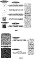
- each ⁇ i u,v maps, ⁇ i u , v ⁇ maps or ⁇ ⁇ i u,v maps may be transmitted to a receiver using four independent monochrome codecs, such as h265/HEVC for example.
- the ⁇ i u,v maps, ⁇ i u , v ⁇ maps or ⁇ ⁇ i u,v maps may be grouped in a single image as represented on figure 8 .
- one method consists in reducing the size of the maps by a factor 2 using the subsampling method, as in the second embodiment, and then in joining the ⁇ i u,v maps, ⁇ i u , v ⁇ maps or ⁇ ⁇ i u,v maps each in a quadrant of an image having the same size as the color map.
- This method is usually named "frame packing" as it packs several frame into a single one.
- Adequate meta-data should be transmitted, for instance in the SEI message, to signal the way the frame packing has been performed such that the decoder can adequately unpack the frames.
- the packed maps into a single frame can be then transmitted using a single monochrome codec, such as, but not limited to,h265/HEVC for example.
- the SEI message as presented in Table 1 must also contain a flag indicating a frame packing method has been used to pack the 4 maps in a single one (refer to Table1b).
- Table 1b Length (bytes) Name Comment 1 Message Type Value should be fixed in MPEG committee 1 Representation type '2points coordinates' or 'one point plus one vector' 4 z1 Z coordinate of the first plane 4 z2 if type '2points coordinates', Z coordinate of the second plane 1
- the description message (SEI for instance) can contain common information (representation type, z1 and z2) plus the description parameters of the 4 maps ( ⁇ i u,v maps, ⁇ i u , v ⁇ maps or ⁇ ⁇ i u,v ) for each camera as shown in table 2.
- ⁇ i u,v maps, ⁇ i u , v ⁇ maps or ⁇ ⁇ i u,v maps may be transmitted to a receiver using monochrome codecs taking into account the multi-view aspect of the configuration such as MPEG Multiview Video coding (MVC) or MPEG Multiview High Efficiency Video Coding (MV-HEVC) for example.
- MVC MPEG Multiview Video coding
- MV-HEVC MPEG Multiview High Efficiency Video Coding
- Length (bytes) Name Comment 1 Message Type Value should be fixed in MPEG committee 1 Representation type '2points coordinates' or 'one point plus one vector' 4 z1 Z coordinate of the first plane 4 z2 if type '2points coordinates', Z coordinate of the second plane
- the SEI message comprises a flag indicating to the receiver that no change has occurred on the ⁇ i u,v maps, ⁇ i u , v ⁇ maps or ⁇ ⁇ i u,v since their last transmission.
- the color maps use the YUV or RGB format and are coded with a video coder such as MPEG- 4 AVC, h265/HEVC, or h266, etc. or an image coder such as JPEG, JPEG2000, MJEG.
- a video coder such as MPEG- 4 AVC, h265/HEVC, or h266, etc.
- an image coder such as JPEG, JPEG2000, MJEG.
- color maps may be coded relatively using the MV-HEVC codec.
Abstract
The present invention relates to the transmission of sets of data and metadata and more particularly to the transmission of light-field contents. Light-field data take up large amounts of storage space which makes storage cumbersome and processing less efficient. In addition light-field acquisition devices are extremely heterogeneous and each camera has its own proprietary file format. Since acquired light-field data from different cameras have a diversity of formats a complex processing is induced on the receiver side. To this end, it is proposed a method for encoding a signal representative of a light-field content in which the parameters representing the rays of light sensed by the different pixels of the sensor are mapped on the sensor. A second set of encoded parameters are used to reconstruct the light-field content from the parameters representing the rays of light sensed by the different pixels of the sensor.
Description
- The present invention relates to the transmission of sets of data and metadata and more particularly to the transmission of light-field contents.
- The acquisition of four-dimensional or 4D light-field data, which can be viewed as a sampling of a 4D light field, i.e. the recording of light rays, is explained in the article "Understanding camera trade-offs through a Bayesian analysis of light field projections" by Anat Levin and al., which has been published in the conference proceedings ot ECCV 2008.
- Compared to classical two-dimensional or 2D images obtained from a camera, 4D light-field data enable a user to have access to more post-processing features that enhance the rendering of images and the interactivity with the user. For example, with 4D light-field data, it is possible to perform refocusing of images with freely selected distances of focalization meaning that the position of a focal plane can be specified/selected a posteriori, as well as changing slightly the point of view in the scene of an image.
- There are several ways to represent 4D light-field data. Indeed, in the Chapter 3.3 of the Ph.D dissertation thesis entitled "Digital Light Field Photography" by Ren Ng, published in July 2006, three different ways to represent 4D light-field data are described. Firstly, 4D light-field data can be represented, when recorded by a plenoptic camera by a collection of microlens images. 4D light-field data in this representation are named raw images or raw 4D light-field data. Secondly, 4D light-field data can be represented, either when recorded by a plenoptic camera or by a camera array, by a set of sub-aperture images. A sub-aperture image corresponds to a captured image of a scene from a point of view, the point of view being slightly different between two sub-aperture images. These sub-aperture images give information about the parallax and depth of the imaged scene. Thirdly, 4D light-field data can be represented by a set ot epipolar images see for example the article entitled : "Generating EPI Representation of a 4D Light Fields with a Single Lens Focused Plenoptic Camera", by S. Wanner and al., published in the conference proceedings ot ISVC 2011.
- Light-field data take up large amounts of storage space which makes storage cumbersome and processing less efficient. In addition light-field acquisition devices are extremely heterogeneous. Light-field cameras are of different types for example plenoptic or camera arrays. Within each type there are many differences such as different optical arrangements, or micro-lenses of different focal lengths. Each camera has its own proprietary file format. At present there is no standard supporting the acquisition and transmission of multi-dimensional information for an exhaustive over-view of the different parameters upon which a light-field depends. Since acquired light-field data from different cameras have a diversity of formats a complex processing is induced on the receiver side.
- The present invention has been devised with the foregoing in mind.
- According to a first aspect of the invention there is provided a computer implemented method for encoding a signal representative of a light-field content said method comprising:
- encoding, for at least one pixel of a sensor, a first set of parameters representing a ray of light sensed by said pixel,
- encoding a second set of parameters intended to be used to reconstruct the light-field content from the first set of parameters.
- The parameters transmitted according to the encoding method according to an embodiment of the invention are independent of the optical acquisition system used to acquire the light-field content intended to be transmitted and processed by a receiving device.
- In the method according to an embodiment of the invention, the parameters representing the rays of light sensed by the different pixels of the sensor of the optical acquisition system, i.e. the parameters of the first set of parameters, are mapped on the sensor. Thus, these parameters can be considered as pictures. For example, when a ray of light sensed by a pixel of the optical acquisition system is represented by four parameters, the parameters representing the rays of light sensed by the pixels of the sensor of the optical acquisition system are grouped in four pictures.
- Such pictures can be encoded and transmitted according to video standards such as MPEG-4 part 10 AVC (also called h264), h265/HEVC or their probable successor h266, and transmitted in a joined video bitstream. The second encoded set may be encoded using Supplemental enhancement information (SEI) messages. The format defined in the method according to an embodiment of the invention enables a strong compression of the data to be transmitted without introducing any strong error (lossless coding) or a limited amount of errors (lossy coding).
- The method according to an embodiment of the invention is not limited to light-field data directly acquired by an optical device. These data may be Computer Graphics Image (CGI) that are totally or partially simulated by a computer for a given scene description. Another source of light-field data may be post-produced data that are modified, for instance color graded, light-field data obtained from an optical device or CGI. It is also now common in the movie industry to have data that are a mix of both data acquired using an optical acquisition device, and CGI data. It is to be understood that the pixel of a sensor can be simulated by a computer-generated scene system and, by extension, the whole sensor can be simulated by said system. From here, it is understood that any reference to a "pixel of a sensor" or a "sensor" can be either a physical object attached to an optical acquisition device or a simulated entity obtained by a computer-generated scene system.
- According to an embodiment of the encoding method, said encoding method further comprises:
- encoding a third set of parameters representing color data associated to the ray of light represented by said first set of parameters.
- According to an embodiment of the encoding method, at least one parameter of the first set of parameters represents a distance between a coordinate of said ray of light and a plane fitting a set of coordinates of a plurality of rays of light sensed by a plurality of pixels of the optical acquisition system, and at least one parameter of the second set of parameters represents coordinates of the fitting plane.
- Encoding the distance between a coordinate of the ray of light and a plane fitting a set of coordinates of a plurality of rays of light sensed by the different pixels of the sensor enables compressing the data to be transmitted since the amplitude between the different values of the computed distances is usually lower than the amplitude between the different values of the coordinates.
- According to an embodiment of the encoding method, at least one parameter of the first set of parameters represents:
- a difference between a value representing the ray of light sensed by said pixel and a value representing a ray of light sensed by another pixel preceding said pixel in a row of the sensor, or
- when said pixel is the first pixel of a row of the sensor, a difference between a value representing the ray of light sensed by said pixel and a value representing a ray of light sensed by the first pixel of a row preceding the row to which said pixel belongs.
- The value representing the ray of light could be either the coordinates representing the ray of light or the distance between the coordinates or planes fitting sets of coordinates of a plurality of rays of light sensed by the different pixels of the sensor.
- This enables compressing the data by reducing the amplitude between the different values of the parameters to be transmitted.
- According to an embodiment of the encoding method, independent codecs are used to encode the parameters of the first set of parameters.
- According to an embodiment of the encoding method, when the second set of parameters comprises a parameter indicating that the first set of parameters is unchanged since a last transmission of the first set of parameters, only said second set of parameters is transmitted.
- This enables to reduce the amount of data to be transmitted to the decoding devices.
- According to an embodiment of the encoding method, the light-field data is made of a sequence of subsets of light-field data. For instance, the sub-sets are indexed temporally in order to represent a dynamic or moving scene. Typically, an element (or sub-set) of the sequence is called a frame. Under this condition, the transmission rate, usually characterized by, but no limited to, a number of frames per second, of the signal representative of the light-content is higher than the transmission rate of the encoded first set of parameters and the encoded second set of parameters.
- This enables to reduce the amount of data to be transmitted to the decoding devices.
- Another object of the invention concerns a device for encoding a signal representative of a light-field content comprising a processor configured to:
- encode, for at least one pixel of a sensor, a first set of parameters representing a ray of light sensed by said pixel,
- encode a second set of parameters intended to be used to reconstruct the light-field content from the first set of parameters.
- Another aspect of the invention concerns a computer implemented method for decoding a signal representative of a light-field content said method comprising:
- decoding, for at least one pixel of a sensor, a first set of parameters representing a ray of light sensed by said pixel,
- decoding a second set of parameters intended to be used to reconstruct the light-field content from the first set of parameters,
- reconstructing the light-field content based on the decoded first set of parameters and the decoded second set of parameters.
- According to an embodiment of the decoding method, said encoding method further comprises:
- decoding a third set of parameters representing color data associated to the ray of light represented by said first set of parameters,
- reconstructing the light-field content based on a decoded third set of parameters together with the decoded first set of parameters and the decoded second set of parameters.
- Another aspect of the invention concerns a device for decoding a signal representative of a light-field content comprising a processor configured to:
- decode, for at least one pixel of a sensor, a first set of parameters representing a ray of light sensed by said pixel,
- decode a second set of parameters intended to be used to reconstruct the light-field content from the first set of parameters,
- reconstruct the light-field content based on the decoded first set of parameters and the decoded second set of parameters.
- Another aspect of the invention concerns a signal transmitted by a device for encoding a signal representative of a light-field content to a device for decoding said signal representative of a light-field content, said signal carrying a message comprising:
- a first set of parameters representing a ray of light sensed by at least one pixel of a sensor,
- a second set of parameters intended to be used to reconstruct the light-field content from the first set of parameters,
- the reconstruction of the light-field content by the decoding device is based on a decoded first set of parameters and a decoded second set of parameters.
- Some processes implemented by elements of the invention may be computer implemented. Accordingly, such elements may take the form of an entirely hardware embodiment, an entirely software embodiment (including firmware, resident software, micro-code, etc.) or an embodiment combining software and hardware aspects that may all generally be referred to herein as a "circuit", "module" or "system'. Furthermore, such elements may take the form of a computer program product embodied in any tangible medium of expression having computer usable program code embodied in the medium.
- Since elements of the present invention can be implemented in software, the present invention can be embodied as computer readable code for provision to a programmable apparatus on any suitable carrier medium. A tangible carrier medium may comprise a storage medium such as a floppy disk, a CD-ROM, a hard disk drive, a magnetic tape device or a solid state memory device and the like. A transient carrier medium may include a signal such as an electrical signal, an electronic signal, an optical signal, an acoustic signal, a magnetic signal or an electromagnetic signal, e.g. a microwave or RF signal.
- Embodiments of the invention will now be described, by way of example only, and with reference to the following drawings in which:
-
Figure 1 is a block diagram of a light-field camera device in accordance with an embodiment of the invention; -
Figure 2 is a block diagram illustrating a particular embodiment of a potential implementation of light-field data formatting module, -
Figure 3 illustrates a ray of light passing through two reference planes P1 and P2 used for parameterization, -
Figure 4 illustrates a ray of light passing through a reference plane P3 located at known depths z3 , -
Figure 5 is a flow chart illustrating the steps of a method for formatting the light-field data according to an embodiment of the invention, -
Figure 6 is a flow chart illustrating the steps of a method for formatting the light-field data according to an embodiment of the invention, -
Figure 7 represents the χiu,v maps,
u,v maps when transmitted to a receiver using four independent monochrome codecs, -
Figure 8 represents_the χiu,v maps,
u,v maps when grouped in a single image. - As will be appreciated by one skilled in the art, aspects of the present principles can be embodied as a system, method or computer readable medium. Accordingly, aspects of the present principles can take the form of an entirely hardware embodiment, an entirely software embodiment, (including firmware, resident software, micro-code, and so forth) or an embodiment combining software and hardware aspects that can all generally be referred to herein as a "circuit", "module", or "system". Furthermore, aspects of the present principles can take the form of a computer readable storage medium. Any combination of one or more computer readable storage medium(a) may be utilized.
- Embodiments of the invention provide formatting of light-field data for further processing applications such as format conversion, refocusing, viewpoint change, etc. The provided formatting enables a proper and easy reconstruction of the light-field data on the receiver side in order to process it. An advantage of the provided format is that it is agnostic to the device used to acquire the light-field data.
-
Figure 1 is a block diagram of a light-field camera device in accordance with an embodiment of the invention. The light-field camera comprises an aperture/shutter 102, a main (objective)lens 101, amicro lens array 110 and a photosensor array. In some embodiments the light-field camera includes a shutter release that is activated to capture a light-field image of a subject or scene. - The
photosensor array 120 provides light-field image data which is acquired by LFData acquisition module 140 for generation of a light-field data format by light-fielddata formatting module 150 and/or for processing by light-field data processor 155. Light-field data may be stored, after acquisition and after processing, inmemory 190 in a raw data format, as sub aperture images or focal stacks, or in a light-field data format in accordance with embodiments of the invention. - In the illustrated example, the light-field
data formatting module 150 and the light-field data processor 155 are disposed in or integrated into the light-field camera 100. In other embodiments of the invention the light-fielddata formatting module 150 and/or the light-field data processor 155 may be provided in a separate component external to the light-field capture camera. The separate component may be local or remote with respect to the light-field image capture device. It will be appreciated that any suitable wired or wireless protocol may be used for transmitting light-field image data to theformatting module 150 or light-field data processor 155; for example the light-field data processor may transfer captured light-field image data and/ or other data via the Internet, a cellular data network, a WiFi network, a Bluetooth®) communication protocol, and/ or any other suitable means. - The light-field
data formatting module 150 is configured to generate data representative of the acquired light-field, in accordance with embodiments of the invention. The light-fielddata formatting module 150 may be implemented in software, hardware or a combination thereof. - The light-
field data processor 155 is configured to operate on raw light-field image data received directly from the LFdata acquisition module 140 for example to generate formatted data and metadata in accordance with embodiments of the invention. Output data, such as, for example, still images, 2D video streams, and the like of the captured scene may be generated. The light-field data processor may be implemented in software, hardware or a combination thereof. - In at least one embodiment, the light-
field camera 100 may also include auser interface 160 for enabling a user to provide user input to control operation ofcamera 100 bycontroller 170. Control of the camera may include one or more of control of optical parameters of the camera such as shutter speed, or in the case of an adjustable light-field camera, control of the relative distance between the microlens array and the photosensor, or the relative distance between the objective lens and the microlens array. In some embodiments the relative distances between optical elements of the light-field camera may be manually adjusted. Control of the camera may also include control of other light-field data acquisition parameters, light-field data formatting parameters or light-field processing parameters of the camera. Theuser interface 160 may comprise any suitable user input device(s) such as a touchscreen, buttons, keyboard, pointing device, and/ or the like. In this way, input received by the user interface can be used to control and/ or configure the LFdata formatting module 150 for controlling the data formatting, theLF data processor 155 for controlling the processing of the acquired light-field data andcontroller 170 for controlling the light-field camera 100. - The light-field camera includes a
power source 180, such as one or more replaceable or rechargeable batteries. The light-field camera comprisesmemory 190 for storing captured light-field data and/or processed light-field data or other data such as software for implementing methods of embodiments of the invention. The memory can include external and/ or internal memory. In at least one embodiment, the memory can be provided at a separate device and/ or location fromcamera 100. In one embodiment, the memory includes a removable/swappable storage device such as a memory stick. - The light-field camera may also include a display unit 165 (e.g., an LCD screen) for viewing scenes in front of the camera prior to capture and/or for viewing previously captured and/or rendered images. The
screen 165 may also be used to display one or more menus or other information to the user. The light-field camera may further include one or more I/O interfaces 195, such as FireWire or Universal Serial Bus (USB) interfaces, or wired or wireless communication interfaces for data communication via the Internet, a cellular data network, a WiFi network, a Bluetooth®) communication protocol, and/ or any other suitable means. The I/O interface 195 may be used for transferring data, such as light-field representative data generated by LF data formatting module in accordance with embodiments of the invention and light-field data such as raw light-field data or data processed byLF data processor 155, to and from external devices such as computer systems or display units, for rendering applications. -
Figure 2 is a block diagram illustrating a particular embodiment of a potential implementation of light-fielddata formatting module 250 and the light-field data processor 253. - The
circuit 200 includesmemory 290, amemory controller 245 andprocessing circuitry 240 comprising one or more processing units (CPU(s)). The one ormore processing units 240 are configured to run various software programs and/or sets of instructions stored in thememory 290 to perform various functions including light-field data formatting and light-field data processing. Software components stored in the memory include a data formatting module (or set of instructions) 250 for generating data representative of acquired light data in accordance with embodiments of the invention and a light-field data processing module (or set of instructions) 255 for processing light-field data in accordance with embodiments of the invention. Other modules may be included in the memory for applications of the light-field camera device such as anoperating system module 251 for controlling general system tasks (e.g. power management, memory management) and for facilitating communication between the various hardware and software components of thedevice 200, and aninterface module 252 for controlling and managing communication with other devices via I/O interface ports. - Embodiments of the invention provide a representation of light-field data based on rays of light sensed by the pixels of the sensor of a camera or simulated by a computer-generated scene system. Indeed, another source of light-field data may be post-produced data that are modified, for instance color graded, light-field data obtained from an optical device or CGI. It is also now common in the movie industry to have data that are a mix of both data acquired using an optical acquisition device, and CGI data. It is to be understood that the pixel of a sensor can be simulated by a computer-generated scene system and, by extension, the whole sensor can be simulated by said system. From here, it is understood that any reference to a "pixel of a sensor" or a "sensor" can be either a physical object attached to an optical acquisition device or a simulated entity obtained by a computer-generated scene system.
- Knowing that whatever the type of acquisition system, to a pixel of the sensor of said acquisition system corresponds at least a linear light trajectory, or ray of light, in space outside the acquisition system, data representing the ray of light in a three-dimensional (or 3D) space are computed.
- In a first embodiment,
Figure 3 illustrates a ray of light passing through two reference planes P1 and P2 used for parameterization positioned parallel to one another and located at known depths z1 and z2 respectively. The ray of light intersects the first reference plane P1 at depth z1 at intersection point (x1, y1 ) and intersects the second reference plane P2 at depth z2 at intersection point (x2, y2 ). In this way, given z1 and z2 , the ray of light can be identified by four coordinates (x1, y1, x2, y2 ). The light-field can thus be parameterized by a pair of reference planes for parameterization P1, P2 also referred herein as parametrization planes, with each ray of light being represented as a point (x 1, y 1, x 2, y 2,) ∈ R4 in 4D ray space. - In a second embodiment represented on
Figure 4 , the ray of light is parametrized by means a point of intersection between a reference plane P3 located at known depths z3 and the ray of light. The ray of light intersects the reference plane P3 at depth z3 at intersection point (x3, y3 ). A normalized vector v, which provides the direction of the ray of light in space has the following coordinates :

- According to this second embodiment, the ray of light may be identified by four coordinates (x 3, y 3, vx , vy ). The light-field can thus be parameterized by a reference plane for parameterization P3 also referred herein as parametrization plane, with each ray of light being represented as a point (x 3, y 3, vx , vy ) ∈ R4 in 4D ray space.
- The parameters representing a ray of light in 4D ray space are computed by the light-field
data formatting module 150.Figure 5 is a flow chart illustrating the steps of a method for formatting the light-field data acquired by thecamera 100 according to an embodiment of the invention. This method is executed by the light-fielddata formatting module 150. - In case the light-field acquisition system is calibrated using a pinhole model, the basic projection model, without distortion, is given by the following equation:

- f is the focal length of the main lens of the
camera 100, - Cu and Cv are the coordinates of the intersection of the optical axis of the
camera 100 with the sensor, - (Xc , Yc, Zc, 1)T is the position in the camera coordinate system of a point in the space sensed by the camera,
- (u, V, 1)T are the coordinates, in the sensor coordinate system, of the projection of the point which coordinates are (Xc Yc, Zc, 1)T in the camera coordinate system on the sensor of the camera.
- In a
step 501, the light-fielddata formatting module 150 computes the coordinates of a vector V representing the direction of the ray of light in space that is sensed by the pixel of the sensor which coordinates are (u, v, 1)T in the sensor coordinate system. In the sensor coordinate system, the coordinates of vector V are:
- In the pinhole model, the coordinates of the intersection of the ray of light sensed by the pixel which coordinates are (u, v, 1)T, with a plane placed at coordinate Z 1 from the pinhole and parallel to the sensor plane are:

step 502. - If several acquisition are mixed, i.e. acquisition of light-field data by different types of cameras, then a single coordinate system is used. In this situation, modifications of coordinates of the points and vectors should be modified accordingly.
- According to an embodiment of the invention, the sets of coordinates defining the rays of light sensed by the pixels of the sensor of the camera and computed during
steps - In an embodiment of the invention, these maps are associated with a color map of the light-field data to be transmitted to a receiver. Thus in this embodiment, to each pixel (u, v) of the sensor of the camera, parameter representative of the color data associated to a ray of light sensed by a given pixel and a quadruplet of floating point values (χ 1 χ 2 χ 3 χ 4) which correspond either to (x 1, y 1, x 2, y 2) when light-field can thus be parameterized by a pair of reference planes for parameterization P1, P2 or (x 3, y 3, vx , vy ,) when the ray of light is parametrized by means of a normalized vector. In the following description, the quadruplet of floating point values (χ 1 χ 2 χ 3 χ 4) is given by:


- In another embodiment, the acquisition system is not calibrated using a pinhole model, consequently the parametrization by two planes is not recalculated from a model. Instead, the parametrization by two planes has to be measured during a calibration operation of the camera. This may be for instance the case for a plenoptic camera which includes in between the main lens and the sensor of the camera a micro-lens array.
- In yet another embodiment, these maps are directly simulated by a computer-generated scene system or post-produced from acquired data.
- Since a ray of light sensed by a pixel of the sensor of the camera is represented by a quadruplet (χ 1 χ 2 χ 3 χ 4) of floating point, it is possible to put these four parameters into four maps of parameters, e.g. a first map comprising the parameter χ 1 of each ray of light sensed by a pixel of the sensor of the camera, a second map comprising the parameter χ 2, a third map comprising the parameter χ 3 and a fourth map comprising the parameter χ 4. Each of the four above-mentioned maps, called χi maps, have the same size as the acquired light-field image itself but have floating points content.
- After some adaptations taking into account the strong correlation between parameters representing rays of light sensed by adjacent pixels and arranging the population of rays of light, and consequently the parameters that represent them, these four maps can be compressed using similar tools as for video data.
- In order to compress the values of the floating points (χ 1 χ 2 χ 3 χ 4) and thus reduce the size of the χi maps to be transmitted, the light-field
data formatting module 150 computes, in astep 503, for each χi maps an equation of a plane fitting the values of said parameter χi comprised in the χi map. The equation of the fitting plane for the parameter χi is given by:
- In a
step 504, for each χi map, parameters αi , βi , γi are computed to minimize the error:
step 504 is a parameter:
- It possible to compress the value


step 505. - Then, in a
step 506, a value


step 507, the light-fielddata formatting module 150 generates four maps,


- In a
step 508, the light-fielddata formatting module 150 generates a SEI (Supplemental Enhancement Information) message comprising the following fixed parameters
u,v maps. These four parameters are considered as metadata conveyed in the SEI message the content of which is given by the following table:Table 1 Length (bytes) Name Comment 1 Message Type Value should be fixed in MPEG committee 1 Representation type '2points coordinates' or 'one point plus one vector' 4 z1 Z coordinate of the first plane 4 z2 if type = '2points coordinates', Z coordinate of the second plane 4 alpha_1 plane coefficient α 4 beta_1 plane coefficient β 4 gamma_1 plane coefficient γ + min(χ'u,v ) 4 max_1 
4 alpha_2 plane coefficient α 4 beta_2 plane coefficient β 4 gamma_2 plane coefficient γ + min(χ'u,v ) 4 max_2 
4 alpha_3 plane coefficient α 4 beta_3 plane coefficient β 4 gamma_3 plane coefficient γ + min(χ'u,v ) 4 max_3 
4 alpha_4 plane coefficient α 4 beta_4 plane coefficient β 4 gamma_4 plane coefficient γ + min(χ'u,v ) 4 max_4 
- On the receiver side, the reciprocal computation enabling to retrieve the original χi
u,v maps is given by - i.

- ii.

- In a
step 509, the
- It possible to further decrease the size of the maps representing the light-field data before their transmission to a receiver. The following embodiments are complementary of the one consisting of minimizing the error:

- In a first embodiment represented on
figure 6 , as the χiu,v maps contain values with low spatial frequencies, it is possible to transmit only the derivative of a signal in a direction in space. - For example, given χ i
0,0 , the value of parameter χi associated to the pixel of coordinates (0,0), the light-fielddata formatting module 150 computes, in astep 601, the difference Δχ i1,0 between the value χ i1,0 of parameter χi associated to the pixel of coordinates (1,0) and the value χ i0,0 of parameter χi associated to the pixel of coordinates (0,0):
- More generally, during
step 601, the light-fielddata formatting module 150 computes a difference between a value of parameter χi associated to a given pixel of the sensor and a value of parameter χi associated to another pixel preceding the given pixel in a row of the sensor of the optical acquisition system or of a computer-generated scene system:
- When the given pixel is the first pixel of a row of the sensor, the light-field
data formatting module 150 computes a difference between a value of parameter χi associated to the given pixel and a value of parameter χi associated to the first pixel of a row preceding the row to which the given pixel belongs:
- In a
step 602, the Δχiu,v maps, the color map and the SEI message, generated duringstep 508, are transmitted to at least a receiver where these data are processed in order to render a light-filed content. - In a second embodiment, as the χi
u,v maps,
u,v maps contain values having very slow spatial frequencies, it is possible to perform a spatial down-sampling in both dimensions of the χiu,v map and then to recover the entire χiu,v map on the receiver side by making a linear interpolation between transmitted samples of said χiu,v maps. - For instance if we can reduce the size of the maps from N_rows*M_columns to from N_rows /2 * M_columns/2. At reception the maps can be extended to original size; the created holes can be filled by an interpolation method (or so-called up-sampling process). A simple bilinear interpolation is generally sufficient

- In a third embodiment represented on
figure 7 , each χiu,v maps,
u,v maps may be transmitted to a receiver using four independent monochrome codecs, such as h265/HEVC for example. - In a fourth embodiment, the χi
u,v maps,
u,v maps may be grouped in a single image as represented onfigure 8 . In order to reach this goal, one method consists in reducing the size of the maps by afactor 2 using the subsampling method, as in the second embodiment, and then in joining the χiu,v maps,
u,v maps each in a quadrant of an image having the same size as the color map. This method is usually named "frame packing" as it packs several frame into a single one. Adequate meta-data should be transmitted, for instance in the SEI message, to signal the way the frame packing has been performed such that the decoder can adequately unpack the frames. The packed maps into a single frame can be then transmitted using a single monochrome codec, such as, but not limited to,h265/HEVC for example. - In this case, the SEI message as presented in Table 1 must also contain a flag indicating a frame packing method has been used to pack the 4 maps in a single one (refer to Table1b).
Table 1b Length (bytes) Name Comment 1 Message Type Value should be fixed in MPEG committee 1 Representation type '2points coordinates' or 'one point plus one vector' 4 z1 Z coordinate of the first plane 4 z2 if type = '2points coordinates', Z coordinate of the second plane 1 Packing mode 0: means no frame packing (separated single maps); 1: means frame packing (single 4 quadrants map) 4 alpha_1 plane coefficient α 4 beta_1 plane coefficient β 4 gamma_1 plane coefficient γ + min(χ'u,v ) 4 max_1 
4 alpha_2 plane coefficient α 4 beta_2 plane coefficient β 4 gamma_2 plane coefficient γ + min(χ'u,v ) 4 max_2 
4 alpha_3 plane coefficient α 4 beta_3 plane coefficient β 4 gamma_3 plane coefficient γ + min(χ'u,v ) 4 max_3 
4 alpha_4 plane coefficient α 4 beta_4 plane coefficient β 4 gamma_4 plane coefficient γ + min(χ'u,v ) 4 max_4 
- When several cameras are grouped to form a rig, it is better and more consistent to define a single world coordinate system and 2 parametrization planes common for all the cameras. Then the description message (SEI for instance) can contain common information (representation type, z1 and z2) plus the description parameters of the 4 maps (χi
u,v maps,
u,v ) for each camera as shown in table 2. - In that case χi
u,v maps,
u,v maps may be transmitted to a receiver using monochrome codecs taking into account the multi-view aspect of the configuration such as MPEG Multiview Video coding (MVC) or MPEG Multiview High Efficiency Video Coding (MV-HEVC) for example.Length (bytes) Name Comment 1 Message Type Value should be fixed in MPEG committee 1 Representation type '2points coordinates' or 'one point plus one vector' 4 z1 Z coordinate of the first plane 4 z2 if type = '2points coordinates', Z coordinate of the second plane For each set of 4 component maps Length (bytes) Name Comment 1 Packing mode 0: means no frame packing (single map); 1: means frame packing (4 quadrants) 4 alpha_1 plane coefficient α 4 beta_1 plane coefficient β 4 gamma_1 plane coefficient γ + min(χ'u,v ) 4 max_1 
4 alpha_2 plane coefficient α 4 beta_2 plane coefficient β 4 gamma_2 plane coefficient γ + min(χ'u,v ) 4 max_2 
4 alpha_3 plane coefficient α 4 beta_3 plane coefficient β 4 gamma_3 plane coefficient γ + min(χ'u,v ) 4 max_3 
4 alpha_4 plane coefficient α 4 beta_4 plane coefficient β 4 gamma_4 plane coefficient γ + min(χ'u,v ) 4 max_4 
- Table 2In a fifth embodiment, when modifications of the χi
u,v maps,
u,v maps are null during a certain amount of time, these χiu,v maps,
u,v are marked as skipped and are not transferred to the receiver. In this case, the SEI message comprises a flag indicating to the receiver that no change has occurred on the χiu,v maps,
u,v since their last transmission. The content of such a SEI message is shown on table 3:Length (bytes) Name Comment 1 Message Type Value should be fixed in MPEG committee 1 Skip_flag 0: means further data are present; 1 means keep previous registered parameters If !skip_flag Length (bytes) Name Comment 1 Representation type '2points coordinates' or 'one point plus one vector' 4 z1 Z coordinate of the first plane 4 z2 if type = '2points coordinates', Z coordinate of the second plane For each quadrant Length (bytes) Name Comment 1 Packing mode 0: means no frame packing (single map); 1: means frame packing (4 quadrants) 4 alpha_1 plane coefficient α 4 beta_1 plane coefficient β 4 gamma_1 plane coefficient γ + min(χ'u,v ) 4 max_1 
4 alpha_2 plane coefficient α 4 beta_2 plane coefficient β 4 gamma_2 plane coefficient γ + min(χ'u,v ) 4 max_2 
4 alpha_3 plane coefficient α 4 beta_3 plane coefficient β 4 gamma_3 plane coefficient γ + min(χ'u,v ) 4 max_3 
4 alpha_4 plane coefficient α beta_4 plane coefficient β 4 gamma_4 plane coefficient γ + min(χ'u,v ) 4 max_4 
- Table 3In a sixth embodiment, as the modifications of acquisition system parameters, represented in the χi
u,v maps,
u,v are slowly modified in time, it is worthwhile to transmit them to a receiver with a frame rate slower than the frame rate of the color map. The frequency of the transmission of the χiu,v maps,
u,v must be at least the one of the IDR frames. - In a seventh embodiment, the color maps use the YUV or RGB format and are coded with a video coder such as MPEG- 4 AVC, h265/HEVC, or h266, etc. or an image coder such as JPEG, JPEG2000, MJEG. When several cameras are used to acquire the light-field content, color maps may be coded relatively using the MV-HEVC codec.
- Although the present invention has been described hereinabove with reference to specific embodiments, the present invention is not limited to the specific embodiments, and modifications will be apparent to a skilled person in the art which lie within the scope of the present invention.
- Many further modifications and variations will suggest themselves to those versed in the art upon making reference to the foregoing illustrative embodiments, which are given by way of example only and which are not intended to limit the scope of the invention, that being determined solely by the appended claims. In particular the different features from different embodiments may be interchanged, where appropriate.
Claims (14)
- A computer implemented method for encoding a signal representative of a light-field content said method comprising:- encoding, for at least one pixel of a sensor, a first set of parameters representing a ray of light sensed by said pixel,- encoding a second set of parameters intended to be used to reconstruct the light-field content from the first set of parameters.
- The method according to claim 1 further comprising:- encoding a third set of parameters representing color data associated to the ray of light represented by said first set of parameters.
- The method according to claim 1 or 2 wherein at least one parameter of the first set of parameters represents a distance between a coordinate of said ray of light and a plane fitting a set of coordinates of a plurality of rays of light sensed by a plurality of pixels of the optical acquisition system, and at least one parameter of the second set of parameters represents coordinates of the fitting plane.
- The method according to any of the preceding claims wherein at least one parameter of the first set of parameters represents:- a difference between a value representing the ray of light sensed by said pixel and a value representing a ray of light sensed by another pixel preceding said pixel in a row of the sensor, or- when said pixel is the first pixel of a row of the sensor, a difference between a value representing the ray of light sensed by said pixel and a value representing a ray of light sensed by the last pixel of a row preceding the row to which said pixel belongs.
- The method according to any of the preceding claims wherein independent codecs are used to encode the parameters of the first set of parameters.
- The method according to any of the preceding claims wherein, when the second set of parameters comprises a parameter indicating that the first set of parameters is unchanged since a last transmission of the first set of parameters, only said second set of parameters is transmitted.
- The method according to claim 2 wherein a transmission rate of the signal representative of the light-content is higher than the transmission rate of the encoded first set of parameters and the encoded second set of parameters.
- A device for encoding a signal representative of a light-field content comprising a processor configured to:- encode, for at least one pixel of a sensor, a first set of parameters representing a ray of light sensed by said pixel,- encode a second set of parameters intended to be used to reconstruct the light-field content from the first set of parameters.
- A computer implemented method for decoding a signal representative of a light-field content said method comprising:- decoding, for at least one pixel of a sensor, a first set of parameters representing a ray of light sensed by said pixel,- decoding a second set of parameters intended to be used to reconstruct the light-field content from the decoded first set of parameters,- reconstructing the light-field content based on the decoded first set of parameters and the decoded second set of parameters.
- The method according to claim 9 further comprising:- decoding a third set of parameters representing color data associated to the ray of light represented by said first set of parameters,- reconstructing the light-field content based on a decoded third set of parameters together with the decoded first set of parameters and the decoded second set of parameters.
- A device for decoding a signal representative of a light-field content comprising a processor configured to:- decode, for at least one pixel of a sensor, a first set of parameters representing a ray of light sensed by said pixel,- decode a second set of parameters intended to be used to reconstruct the light-field content from the first set of parameters,- reconstruct the light-field content based on the decoded first set of parameters and the decoded second set of parameters.
- Signal transmitted by a device for encoding a signal representative of a light-field content to a device for decoding said signal representative of a light-field content, said signal carrying a message comprising:- a first set of parameters representing a ray of light sensed by at least one pixel of a sensor,- a second set of parameters intended to be used to reconstruct the light-field content from the first set of parameters,the reconstruction of the light-field content by the decoding device is based on a decoded first set of parameters and a decoded second set of parameters.
- A computer program characterized in that it comprises program code instructions for the implementation of the method for encoding a light-field content according to any of claims 1 to 7 when the program is executed by a processor.
- A computer program characterized in that it comprises program code instructions for the implementation of the method for decoding a light-field content according to any of claims 9 to 10 when the program is executed by a processor.
Priority Applications (12)
| Application Number | Priority Date | Filing Date | Title |
|---|---|---|---|
| EP16305757.3A EP3261347A1 (en) | 2016-06-22 | 2016-06-22 | A method and a device for encoding a signal representative of a light-field content |
| EP17176402.0A EP3261348A1 (en) | 2016-06-22 | 2017-06-16 | A method and a device for encoding a signal representative of a light-field content |
| EP22163305.0A EP4054194A1 (en) | 2016-06-22 | 2017-06-16 | A method and a device for encoding a signal representative of a light-field content |
| RU2017121569A RU2746344C2 (en) | 2016-06-22 | 2017-06-20 | Method and the device for encoding a signal representing the content of a light field |
| MX2017008222A MX2017008222A (en) | 2016-06-22 | 2017-06-20 | A method and a device for encoding a signal representative of a light-field content. |
| CA2971337A CA2971337A1 (en) | 2016-06-22 | 2017-06-20 | A method and a device for encoding a signal representative of a light-field content |
| JP2017120128A JP7171169B2 (en) | 2016-06-22 | 2017-06-20 | Method and Apparatus for Encoding Signals Representing Lightfield Content |
| BR102017013446-6A BR102017013446A2 (en) | 2016-06-22 | 2017-06-21 | METHOD AND DEVICE FOR ENCODING A REPRESENTATIVE SIGN OF A LIGHT FIELD CONTENT |
| AU2017204215A AU2017204215C1 (en) | 2016-06-22 | 2017-06-21 | A method and a device for encoding a signal representative of a light-field content |
| US15/629,951 US11665369B2 (en) | 2016-06-22 | 2017-06-22 | Method and a device for encoding a signal representative of a light-field content |
| CN201710481124.XA CN107529062A (en) | 2016-06-22 | 2017-06-22 | Method and apparatus for being encoded to the signal for representing light field content |
| KR1020170079028A KR102505130B1 (en) | 2016-06-22 | 2017-06-22 | A method and a device for encoding a signal representative of a light-field content |
Applications Claiming Priority (1)
| Application Number | Priority Date | Filing Date | Title |
|---|---|---|---|
| EP16305757.3A EP3261347A1 (en) | 2016-06-22 | 2016-06-22 | A method and a device for encoding a signal representative of a light-field content |
Publications (1)
| Publication Number | Publication Date |
|---|---|
| EP3261347A1 true EP3261347A1 (en) | 2017-12-27 |
Family
ID=56511475
Family Applications (3)
| Application Number | Title | Priority Date | Filing Date |
|---|---|---|---|
| EP16305757.3A Withdrawn EP3261347A1 (en) | 2016-06-22 | 2016-06-22 | A method and a device for encoding a signal representative of a light-field content |
| EP17176402.0A Ceased EP3261348A1 (en) | 2016-06-22 | 2017-06-16 | A method and a device for encoding a signal representative of a light-field content |
| EP22163305.0A Pending EP4054194A1 (en) | 2016-06-22 | 2017-06-16 | A method and a device for encoding a signal representative of a light-field content |
Family Applications After (2)
| Application Number | Title | Priority Date | Filing Date |
|---|---|---|---|
| EP17176402.0A Ceased EP3261348A1 (en) | 2016-06-22 | 2017-06-16 | A method and a device for encoding a signal representative of a light-field content |
| EP22163305.0A Pending EP4054194A1 (en) | 2016-06-22 | 2017-06-16 | A method and a device for encoding a signal representative of a light-field content |
Country Status (10)
| Country | Link |
|---|---|
| US (1) | US11665369B2 (en) |
| EP (3) | EP3261347A1 (en) |
| JP (1) | JP7171169B2 (en) |
| KR (1) | KR102505130B1 (en) |
| CN (1) | CN107529062A (en) |
| AU (1) | AU2017204215C1 (en) |
| BR (1) | BR102017013446A2 (en) |
| CA (1) | CA2971337A1 (en) |
| MX (1) | MX2017008222A (en) |
| RU (1) | RU2746344C2 (en) |
Cited By (1)
| Publication number | Priority date | Publication date | Assignee | Title |
|---|---|---|---|---|
| CN112183637A (en) * | 2020-09-29 | 2021-01-05 | 中科方寸知微(南京)科技有限公司 | Single-light-source scene illumination re-rendering method and system based on neural network |
Families Citing this family (2)
| Publication number | Priority date | Publication date | Assignee | Title |
|---|---|---|---|---|
| CN109792528A (en) * | 2016-09-19 | 2019-05-21 | 交互数字Vc控股公司 | The method and apparatus for indicating the point cloud of scene is reconstructed using light field data |
| CN116528065B (en) * | 2023-06-30 | 2023-09-26 | 深圳臻像科技有限公司 | Efficient virtual scene content light field acquisition and generation method |
Family Cites Families (26)
| Publication number | Priority date | Publication date | Assignee | Title |
|---|---|---|---|---|
| US6097394A (en) * | 1997-04-28 | 2000-08-01 | Board Of Trustees, Leland Stanford, Jr. University | Method and system for light field rendering |
| EP1264281A4 (en) * | 2000-02-25 | 2007-07-11 | Univ New York State Res Found | Apparatus and method for volume processing and rendering |
| US6693964B1 (en) * | 2000-03-24 | 2004-02-17 | Microsoft Corporation | Methods and arrangements for compressing image based rendering data using multiple reference frame prediction techniques that support just-in-time rendering of an image |
| RU2331919C2 (en) * | 2006-03-21 | 2008-08-20 | Алексей Евгеньевич Субботин | Projector encoding |
| US7609906B2 (en) * | 2006-04-04 | 2009-10-27 | Mitsubishi Electric Research Laboratories, Inc. | Method and system for acquiring and displaying 3D light fields |
| US7756407B2 (en) | 2006-05-08 | 2010-07-13 | Mitsubishi Electric Research Laboratories, Inc. | Method and apparatus for deblurring images |
| US20130113981A1 (en) * | 2006-12-01 | 2013-05-09 | Lytro, Inc. | Light field camera image, file and configuration data, and methods of using, storing and communicating same |
| US20100265385A1 (en) * | 2009-04-18 | 2010-10-21 | Knight Timothy J | Light Field Camera Image, File and Configuration Data, and Methods of Using, Storing and Communicating Same |
| US8103111B2 (en) | 2006-12-26 | 2012-01-24 | Olympus Imaging Corp. | Coding method, electronic camera, recording medium storing coded program, and decoding method |
| US8229294B2 (en) * | 2007-12-10 | 2012-07-24 | Mitsubishi Electric Research Laboratories, Inc. | Cameras with varying spatio-angular-temporal resolutions |
| US8749620B1 (en) * | 2010-02-20 | 2014-06-10 | Lytro, Inc. | 3D light field cameras, images and files, and methods of using, operating, processing and viewing same |
| EP2668634B1 (en) * | 2011-01-24 | 2019-04-24 | Intel Corporation | Method and system for acquisition, representation, compression, and transmission of three-dimensional data |
| US9129183B2 (en) * | 2011-09-28 | 2015-09-08 | Pelican Imaging Corporation | Systems and methods for encoding light field image files |
| US20150063466A1 (en) * | 2012-04-06 | 2015-03-05 | Sony Corporation | Decoding device and decoding method, and encoding device and encoding method |
| US9179126B2 (en) * | 2012-06-01 | 2015-11-03 | Ostendo Technologies, Inc. | Spatio-temporal light field cameras |
| GB2503656B (en) * | 2012-06-28 | 2014-10-15 | Canon Kk | Method and apparatus for compressing or decompressing light field images |
| WO2014009603A1 (en) * | 2012-07-02 | 2014-01-16 | Nokia Corporation | Method and apparatus for video coding |
| US9743064B2 (en) * | 2012-09-11 | 2017-08-22 | The Directv Group, Inc. | System and method for distributing high-quality 3D video in a 2D format |
| JP2014086968A (en) | 2012-10-25 | 2014-05-12 | Ricoh Co Ltd | Image processing device, image processing method, and program |
| US9462164B2 (en) * | 2013-02-21 | 2016-10-04 | Pelican Imaging Corporation | Systems and methods for generating compressed light field representation data using captured light fields, array geometry, and parallax information |
| US9582922B2 (en) * | 2013-05-17 | 2017-02-28 | Nvidia Corporation | System, method, and computer program product to produce images for a near-eye light field display |
| US9264661B2 (en) * | 2013-06-07 | 2016-02-16 | Apple Inc. | Adaptive post-processing for mobile video calling system |
| KR102156402B1 (en) * | 2013-11-05 | 2020-09-16 | 삼성전자주식회사 | Method and apparatus for image processing |
| US9414087B2 (en) | 2014-04-24 | 2016-08-09 | Lytro, Inc. | Compression of light field images |
| US9712820B2 (en) * | 2014-04-24 | 2017-07-18 | Lytro, Inc. | Predictive light field compression |
| US9961333B1 (en) * | 2016-06-10 | 2018-05-01 | X Development Llc | System and method for light field projection |
-
2016
- 2016-06-22 EP EP16305757.3A patent/EP3261347A1/en not_active Withdrawn
-
2017
- 2017-06-16 EP EP17176402.0A patent/EP3261348A1/en not_active Ceased
- 2017-06-16 EP EP22163305.0A patent/EP4054194A1/en active Pending
- 2017-06-20 RU RU2017121569A patent/RU2746344C2/en active
- 2017-06-20 JP JP2017120128A patent/JP7171169B2/en active Active
- 2017-06-20 CA CA2971337A patent/CA2971337A1/en active Pending
- 2017-06-20 MX MX2017008222A patent/MX2017008222A/en unknown
- 2017-06-21 AU AU2017204215A patent/AU2017204215C1/en active Active
- 2017-06-21 BR BR102017013446-6A patent/BR102017013446A2/en unknown
- 2017-06-22 US US15/629,951 patent/US11665369B2/en active Active
- 2017-06-22 KR KR1020170079028A patent/KR102505130B1/en active IP Right Grant
- 2017-06-22 CN CN201710481124.XA patent/CN107529062A/en active Pending
Non-Patent Citations (4)
Cited By (2)
| Publication number | Priority date | Publication date | Assignee | Title |
|---|---|---|---|---|
| CN112183637A (en) * | 2020-09-29 | 2021-01-05 | 中科方寸知微(南京)科技有限公司 | Single-light-source scene illumination re-rendering method and system based on neural network |
| CN112183637B (en) * | 2020-09-29 | 2024-04-09 | 中科方寸知微(南京)科技有限公司 | Single-light-source scene illumination re-rendering method and system based on neural network |
Also Published As
| Publication number | Publication date |
|---|---|
| KR20180000319A (en) | 2018-01-02 |
| RU2746344C2 (en) | 2021-04-12 |
| AU2017204215B2 (en) | 2022-04-28 |
| EP4054194A1 (en) | 2022-09-07 |
| JP7171169B2 (en) | 2022-11-15 |
| AU2017204215C1 (en) | 2023-02-02 |
| RU2017121569A (en) | 2018-12-24 |
| EP3261348A1 (en) | 2017-12-27 |
| US11665369B2 (en) | 2023-05-30 |
| JP2018033127A (en) | 2018-03-01 |
| AU2017204215A1 (en) | 2018-01-18 |
| MX2017008222A (en) | 2018-09-10 |
| BR102017013446A2 (en) | 2018-05-02 |
| CA2971337A1 (en) | 2017-12-22 |
| KR102505130B1 (en) | 2023-03-02 |
| RU2017121569A3 (en) | 2020-09-25 |
| CN107529062A (en) | 2017-12-29 |
| US20170374388A1 (en) | 2017-12-28 |
Similar Documents
| Publication | Publication Date | Title |
|---|---|---|
| US20190387211A1 (en) | A method and a device for reconstructing a point cloud representative of a scene using light-field data | |
| JP6837056B2 (en) | Methods and equipment for encoding and decoding light field-based images and corresponding computer program products | |
| CN111615715A (en) | Method, apparatus and stream for encoding/decoding volumetric video | |
| CN101416520B (en) | Efficient encoding of multiple views | |
| CN106131531B (en) | Method for processing video frequency and device | |
| CN111557094A (en) | Method, apparatus and stream for encoding/decoding a volumetric video | |
| US10785502B2 (en) | Method and apparatus for encoding and decoding a light field based image, and corresponding computer program product | |
| Graziosi et al. | Depth assisted compression of full parallax light fields | |
| EP3301926A1 (en) | A method and a device for reconstructing a point cloud representative of a scene using light-field data | |
| US11665369B2 (en) | Method and a device for encoding a signal representative of a light-field content | |
| US20220343549A1 (en) | A method and apparatus for encoding, transmitting and decoding volumetric video | |
| US20230186527A1 (en) | Point cloud data transmission device, point cloud data transmission method, point cloud data reception device, and point cloud data reception method | |
| EP2373046A2 (en) | Super resolution based n-view + n-depth multiview video coding | |
| CN102333230A (en) | Method for improving quality of synthetized virtual views in three-dimensional video system | |
| WO2020072842A1 (en) | Methods and apparatus for depth encoding and decoding | |
| JP7382186B2 (en) | Encoding device, decoding device, and program | |
| Kukolj et al. | 3D content acquisition and coding | |
| US20220345681A1 (en) | Method and apparatus for encoding, transmitting and decoding volumetric video | |
| US20230362409A1 (en) | A method and apparatus for signaling depth of multi-plane images-based volumetric video | |
| US20240020885A1 (en) | Point cloud data transmission method, point cloud data transmission device, point cloud data reception method, and point cloud data reception device | |
| US20230345008A1 (en) | Point cloud data transmission device, point cloud data transmission method, point cloud data reception device, and point cloud data reception method |
Legal Events
| Date | Code | Title | Description |
|---|---|---|---|
| PUAI | Public reference made under article 153(3) epc to a published international application that has entered the european phase |
Free format text: ORIGINAL CODE: 0009012 |
|
| AK | Designated contracting states |
Kind code of ref document: A1 Designated state(s): AL AT BE BG CH CY CZ DE DK EE ES FI FR GB GR HR HU IE IS IT LI LT LU LV MC MK MT NL NO PL PT RO RS SE SI SK SM TR |
|
| AX | Request for extension of the european patent |
Extension state: BA ME |
|
| STAA | Information on the status of an ep patent application or granted ep patent |
Free format text: STATUS: THE APPLICATION IS DEEMED TO BE WITHDRAWN |
|
| 18D | Application deemed to be withdrawn |
Effective date: 20180628 |