RU2744407C1 - System and the method for reducing the amount of sulfur oxides in exhaust gas - Google Patents
System and the method for reducing the amount of sulfur oxides in exhaust gas Download PDFInfo
- Publication number
- RU2744407C1 RU2744407C1 RU2018138239A RU2018138239A RU2744407C1 RU 2744407 C1 RU2744407 C1 RU 2744407C1 RU 2018138239 A RU2018138239 A RU 2018138239A RU 2018138239 A RU2018138239 A RU 2018138239A RU 2744407 C1 RU2744407 C1 RU 2744407C1
- Authority
- RU
- Russia
- Prior art keywords
- spray
- exhaust gas
- cleaning liquid
- column
- waste gas
- Prior art date
Links
Images
Classifications
-
- B—PERFORMING OPERATIONS; TRANSPORTING
- B01—PHYSICAL OR CHEMICAL PROCESSES OR APPARATUS IN GENERAL
- B01D—SEPARATION
- B01D53/00—Separation of gases or vapours; Recovering vapours of volatile solvents from gases; Chemical or biological purification of waste gases, e.g. engine exhaust gases, smoke, fumes, flue gases, aerosols
- B01D53/34—Chemical or biological purification of waste gases
- B01D53/46—Removing components of defined structure
- B01D53/48—Sulfur compounds
- B01D53/50—Sulfur oxides
- B01D53/501—Sulfur oxides by treating the gases with a solution or a suspension of an alkali or earth-alkali or ammonium compound
- B01D53/504—Sulfur oxides by treating the gases with a solution or a suspension of an alkali or earth-alkali or ammonium compound characterised by a specific device
-
- B—PERFORMING OPERATIONS; TRANSPORTING
- B01—PHYSICAL OR CHEMICAL PROCESSES OR APPARATUS IN GENERAL
- B01D—SEPARATION
- B01D47/00—Separating dispersed particles from gases, air or vapours by liquid as separating agent
- B01D47/06—Spray cleaning
- B01D47/063—Spray cleaning with two or more jets impinging against each other
-
- B—PERFORMING OPERATIONS; TRANSPORTING
- B01—PHYSICAL OR CHEMICAL PROCESSES OR APPARATUS IN GENERAL
- B01D—SEPARATION
- B01D53/00—Separation of gases or vapours; Recovering vapours of volatile solvents from gases; Chemical or biological purification of waste gases, e.g. engine exhaust gases, smoke, fumes, flue gases, aerosols
- B01D53/14—Separation of gases or vapours; Recovering vapours of volatile solvents from gases; Chemical or biological purification of waste gases, e.g. engine exhaust gases, smoke, fumes, flue gases, aerosols by absorption
- B01D53/1456—Removing acid components
- B01D53/1481—Removing sulfur dioxide or sulfur trioxide
-
- B—PERFORMING OPERATIONS; TRANSPORTING
- B01—PHYSICAL OR CHEMICAL PROCESSES OR APPARATUS IN GENERAL
- B01D—SEPARATION
- B01D53/00—Separation of gases or vapours; Recovering vapours of volatile solvents from gases; Chemical or biological purification of waste gases, e.g. engine exhaust gases, smoke, fumes, flue gases, aerosols
- B01D53/14—Separation of gases or vapours; Recovering vapours of volatile solvents from gases; Chemical or biological purification of waste gases, e.g. engine exhaust gases, smoke, fumes, flue gases, aerosols by absorption
- B01D53/1493—Selection of liquid materials for use as absorbents
-
- B—PERFORMING OPERATIONS; TRANSPORTING
- B01—PHYSICAL OR CHEMICAL PROCESSES OR APPARATUS IN GENERAL
- B01D—SEPARATION
- B01D53/00—Separation of gases or vapours; Recovering vapours of volatile solvents from gases; Chemical or biological purification of waste gases, e.g. engine exhaust gases, smoke, fumes, flue gases, aerosols
- B01D53/14—Separation of gases or vapours; Recovering vapours of volatile solvents from gases; Chemical or biological purification of waste gases, e.g. engine exhaust gases, smoke, fumes, flue gases, aerosols by absorption
- B01D53/18—Absorbing units; Liquid distributors therefor
- B01D53/185—Liquid distributors
-
- B—PERFORMING OPERATIONS; TRANSPORTING
- B01—PHYSICAL OR CHEMICAL PROCESSES OR APPARATUS IN GENERAL
- B01D—SEPARATION
- B01D53/00—Separation of gases or vapours; Recovering vapours of volatile solvents from gases; Chemical or biological purification of waste gases, e.g. engine exhaust gases, smoke, fumes, flue gases, aerosols
- B01D53/34—Chemical or biological purification of waste gases
- B01D53/74—General processes for purification of waste gases; Apparatus or devices specially adapted therefor
- B01D53/77—Liquid phase processes
- B01D53/78—Liquid phase processes with gas-liquid contact
-
- F—MECHANICAL ENGINEERING; LIGHTING; HEATING; WEAPONS; BLASTING
- F01—MACHINES OR ENGINES IN GENERAL; ENGINE PLANTS IN GENERAL; STEAM ENGINES
- F01N—GAS-FLOW SILENCERS OR EXHAUST APPARATUS FOR MACHINES OR ENGINES IN GENERAL; GAS-FLOW SILENCERS OR EXHAUST APPARATUS FOR INTERNAL COMBUSTION ENGINES
- F01N13/00—Exhaust or silencing apparatus characterised by constructional features ; Exhaust or silencing apparatus, or parts thereof, having pertinent characteristics not provided for in, or of interest apart from, groups F01N1/00 - F01N5/00, F01N9/00, F01N11/00
- F01N13/004—Exhaust or silencing apparatus characterised by constructional features ; Exhaust or silencing apparatus, or parts thereof, having pertinent characteristics not provided for in, or of interest apart from, groups F01N1/00 - F01N5/00, F01N9/00, F01N11/00 specially adapted for marine propulsion, i.e. for receiving simultaneously engine exhaust gases and engine cooling water
-
- F—MECHANICAL ENGINEERING; LIGHTING; HEATING; WEAPONS; BLASTING
- F01—MACHINES OR ENGINES IN GENERAL; ENGINE PLANTS IN GENERAL; STEAM ENGINES
- F01N—GAS-FLOW SILENCERS OR EXHAUST APPARATUS FOR MACHINES OR ENGINES IN GENERAL; GAS-FLOW SILENCERS OR EXHAUST APPARATUS FOR INTERNAL COMBUSTION ENGINES
- F01N3/00—Exhaust or silencing apparatus having means for purifying, rendering innocuous, or otherwise treating exhaust
- F01N3/02—Exhaust or silencing apparatus having means for purifying, rendering innocuous, or otherwise treating exhaust for cooling, or for removing solid constituents of, exhaust
- F01N3/04—Exhaust or silencing apparatus having means for purifying, rendering innocuous, or otherwise treating exhaust for cooling, or for removing solid constituents of, exhaust using liquids
-
- F—MECHANICAL ENGINEERING; LIGHTING; HEATING; WEAPONS; BLASTING
- F23—COMBUSTION APPARATUS; COMBUSTION PROCESSES
- F23J—REMOVAL OR TREATMENT OF COMBUSTION PRODUCTS OR COMBUSTION RESIDUES; FLUES
- F23J15/00—Arrangements of devices for treating smoke or fumes
- F23J15/02—Arrangements of devices for treating smoke or fumes of purifiers, e.g. for removing noxious material
- F23J15/04—Arrangements of devices for treating smoke or fumes of purifiers, e.g. for removing noxious material using washing fluids
-
- B—PERFORMING OPERATIONS; TRANSPORTING
- B01—PHYSICAL OR CHEMICAL PROCESSES OR APPARATUS IN GENERAL
- B01D—SEPARATION
- B01D2251/00—Reactants
- B01D2251/40—Alkaline earth metal or magnesium compounds
- B01D2251/402—Alkaline earth metal or magnesium compounds of magnesium
-
- B—PERFORMING OPERATIONS; TRANSPORTING
- B01—PHYSICAL OR CHEMICAL PROCESSES OR APPARATUS IN GENERAL
- B01D—SEPARATION
- B01D2251/00—Reactants
- B01D2251/60—Inorganic bases or salts
- B01D2251/602—Oxides
-
- B—PERFORMING OPERATIONS; TRANSPORTING
- B01—PHYSICAL OR CHEMICAL PROCESSES OR APPARATUS IN GENERAL
- B01D—SEPARATION
- B01D2251/00—Reactants
- B01D2251/60—Inorganic bases or salts
- B01D2251/604—Hydroxides
-
- B—PERFORMING OPERATIONS; TRANSPORTING
- B01—PHYSICAL OR CHEMICAL PROCESSES OR APPARATUS IN GENERAL
- B01D—SEPARATION
- B01D2252/00—Absorbents, i.e. solvents and liquid materials for gas absorption
- B01D2252/10—Inorganic absorbents
- B01D2252/103—Water
- B01D2252/1035—Sea water
-
- B—PERFORMING OPERATIONS; TRANSPORTING
- B01—PHYSICAL OR CHEMICAL PROCESSES OR APPARATUS IN GENERAL
- B01D—SEPARATION
- B01D2257/00—Components to be removed
- B01D2257/30—Sulfur compounds
- B01D2257/302—Sulfur oxides
-
- B—PERFORMING OPERATIONS; TRANSPORTING
- B01—PHYSICAL OR CHEMICAL PROCESSES OR APPARATUS IN GENERAL
- B01D—SEPARATION
- B01D2259/00—Type of treatment
- B01D2259/45—Gas separation or purification devices adapted for specific applications
- B01D2259/4566—Gas separation or purification devices adapted for specific applications for use in transportation means
-
- F—MECHANICAL ENGINEERING; LIGHTING; HEATING; WEAPONS; BLASTING
- F01—MACHINES OR ENGINES IN GENERAL; ENGINE PLANTS IN GENERAL; STEAM ENGINES
- F01N—GAS-FLOW SILENCERS OR EXHAUST APPARATUS FOR MACHINES OR ENGINES IN GENERAL; GAS-FLOW SILENCERS OR EXHAUST APPARATUS FOR INTERNAL COMBUSTION ENGINES
- F01N2590/00—Exhaust or silencing apparatus adapted to particular use, e.g. for military applications, airplanes, submarines
- F01N2590/02—Exhaust or silencing apparatus adapted to particular use, e.g. for military applications, airplanes, submarines for marine vessels or naval applications
-
- F—MECHANICAL ENGINEERING; LIGHTING; HEATING; WEAPONS; BLASTING
- F23—COMBUSTION APPARATUS; COMBUSTION PROCESSES
- F23J—REMOVAL OR TREATMENT OF COMBUSTION PRODUCTS OR COMBUSTION RESIDUES; FLUES
- F23J2215/00—Preventing emissions
- F23J2215/20—Sulfur; Compounds thereof
-
- F—MECHANICAL ENGINEERING; LIGHTING; HEATING; WEAPONS; BLASTING
- F23—COMBUSTION APPARATUS; COMBUSTION PROCESSES
- F23J—REMOVAL OR TREATMENT OF COMBUSTION PRODUCTS OR COMBUSTION RESIDUES; FLUES
- F23J2219/00—Treatment devices
- F23J2219/40—Sorption with wet devices, e.g. scrubbers
-
- Y—GENERAL TAGGING OF NEW TECHNOLOGICAL DEVELOPMENTS; GENERAL TAGGING OF CROSS-SECTIONAL TECHNOLOGIES SPANNING OVER SEVERAL SECTIONS OF THE IPC; TECHNICAL SUBJECTS COVERED BY FORMER USPC CROSS-REFERENCE ART COLLECTIONS [XRACs] AND DIGESTS
- Y02—TECHNOLOGIES OR APPLICATIONS FOR MITIGATION OR ADAPTATION AGAINST CLIMATE CHANGE
- Y02T—CLIMATE CHANGE MITIGATION TECHNOLOGIES RELATED TO TRANSPORTATION
- Y02T10/00—Road transport of goods or passengers
- Y02T10/10—Internal combustion engine [ICE] based vehicles
- Y02T10/12—Improving ICE efficiencies
Abstract
Description
Область техники настоящего изобретенияTECHNICAL FIELD OF THE PRESENT INVENTION
[0001] Настоящая заявка относится к области техники очистки отработанного газа. Более конкретно, настоящая заявка относится к очистке отработанного газа морских судов посредством уменьшения содержания оксидов серы (SOx) в этом отработанном газе морских судов с использованием мокрой очистки.[0001] The present application relates to the field of waste gas treatment technology. More specifically, the present application relates to the purification of waste gas from marine vessels by reducing the sulfur oxides (SO x ) content of this waste gas from marine vessels using wet scrubbing.
Предшествующий уровень техники настоящего изобретенияPrior art of the present invention
[0002] Сжигание ископаемого топлива используют в промышленных процессах для множества различных целей. К сожалению, сжигание ископаемого топлива производит несколько загрязняющих веществ, которые оказались вредными для окружающей среды. В частности, оксидные соединения серы и азота представляют собой основные компоненты "кислотного дождя". Сера представляет собой встречающийся в природе элемент, который содержится в сырой нефти и концентрируется в остаточных компонентах в процессе дистилляции сырой нефти. Содержание серы в нефтяном топливе зависит от источника сырой нефти и в меньшей степени от процесса ее переработки. В мировом масштабе ее типичное содержание в топливе составляет приблизительно от 1,5 до 4 мас. %. Указанные значения приводят к высокой концентрации SO2 в топочных газах. Например, когда используют топливо, содержащее 1,5 мас. % серы, концентрация SO2 в выпускаемом газе составляет приблизительно 630 частей на миллион, а когда топливо содержит 4 мас. % серы, концентрация SO2 в выпускаемом газе составляет приблизительно 1700 частей на миллион.[0002] The combustion of fossil fuels is used in industrial processes for a variety of different purposes. Unfortunately, burning fossil fuels produces several pollutants that have proven to be harmful to the environment. In particular, oxide compounds of sulfur and nitrogen are the main components of "acid rain". Sulfur is a naturally occurring element found in crude oil and is concentrated in residual constituents during the distillation of crude oil. The sulfur content of fuel oils depends on the source of the crude oil and to a lesser extent on the refining process. Globally, its typical content in fuel is from about 1.5 to 4 wt. %. These values lead to high SO 2 concentrations in the flue gases. For example, when using a fuel containing 1.5 wt. % sulfur, the concentration of SO 2 in the exhaust gas is approximately 630 ppm, and when the fuel contains 4 wt. % sulfur, the concentration of SO 2 in the exhaust gas is approximately 1700 ppm.
[0003] С учетом вреда, который вызывают оксиды серы (SOx) и оксиды азота (NOx), были разработаны различные процессы очистки и технологии разделения газообразных продуктов горения для удаления указанных компонентов из образующихся при горении топочных газов перед выпуском топочных газов в атмосферу, в частности, потому что сжигание ископаемого топлива производит каждый год много миллионов тонн SO2.[0003] In view of the harm that cause sulfur oxides (SO x) and nitrogen oxides (NO x), have been developed various processes of purification and separation technology of gaseous combustion products for removing said components from produced during combustion of the flue gases before releasing flue gases into the atmosphere in particular because the combustion of fossil fuels produces many million tons of SO 2 each year.
[0004] Для европейских вод впервые в мире были введены более строгие правила, ограничивающие выбросы серы для судов, с вступлением в силу так называемых областей контроля выбросов серы (SECA) в Балтийском море в 2006 году, а затем в Северном море и Ла-Манше в 2007 году.[0004] For European waters, for the first time in the world, stricter rules were introduced to limit sulfur emissions for ships, with the entry into force of the so-called sulfur emission control areas (SECA) in the Baltic Sea in 2006, followed by the North Sea and the English Channel in 2007.
[0005] Согласно директиве Европейского Союза (ЕС) о содержании серы в топливе для морских судов, разрешены только горючие материалы с низким содержанием серы, составляющим менее чем 1,5 мас. %. Кроме того, с 11 августа 2006 года ограничение содержания серы в топливе на уровне 1,5 мас. % распространяется на горючие материалы, используемые на пассажирских судах, эксплуатируемых на регулярной основе и совершающих рейсы с заходом в любой порт ЕС, а не только в пределах SECA. Законодательство ЕС разрешает использование технологий, которые уменьшают содержание серы в выпускаемом газе, в качестве альтернативы использованию горючих материалов с низким содержанием серы (1,5 мас. %). Таким образом, технология должна обеспечивать уменьшение выбросов серы до уровня, который является по меньшей мере равным или не превышает уровень снижения содержания серы в топливе для судовых двигателей.[0005] According to the European Union (EU) directive on the sulfur content of fuels for marine vessels, only combustible materials with a low sulfur content of less than 1.5 wt. %. In addition, from August 11, 2006, the limitation of the sulfur content in the fuel at the level of 1.5 wt. % applies to combustible materials used on passenger ships operating on a regular basis and making voyages calling at any EU port, not just SECA. EU legislation allows the use of technologies that reduce the sulfur content of the exhaust gas, as an alternative to the use of fuels with a low sulfur content (1.5 wt.%). Thus, the technology should be able to reduce sulfur emissions to a level that is at least equal to or not greater than the sulfur reduction in marine engine fuels.
[0006] В большинстве технологий для уменьшения содержания SOx в отработанном газе использованы процессы мокрой очистки, в которых отработанный газ вступает в контакт с водным раствором. Цель указанных процессов представляет собой обеспечение высокоэффективной абсорбции, т.е. абсорбции выше 70-95% SO2. В отношении процесса абсорбции существуют высокие требования, приводящие к относительно немногочисленным проектным решениям. Например, эффективность реакции между компонентами в водном растворе и SOx в фазе очищаемого отработанного газа уменьшается при увеличении температуры реакции, в частности, выше приблизительно 70°С. Однако температура выпускаемого газа составляет приблизительно 300°С, и в результате этого уменьшается эффективность процесса.[0006] Most technologies to reduce SO x in flue gas use wet scrubbing processes in which the flue gas comes into contact with an aqueous solution. The purpose of these processes is to provide highly efficient absorption, i.e. absorption above 70-95% SO 2 . There are high requirements for the absorption process, resulting in relatively few design solutions. For example, the efficiency of the reaction between the components in aqueous solution and SO x in the purified waste gas phase decreases with increasing reaction temperature, in particular above about 70 ° C. However, the temperature of the discharged gas is approximately 300 ° C, and as a result, the efficiency of the process decreases.
[0007] Кроме того, объем выпускаемого отработанного газа является значительным, причем выпуск достигает приблизительно 12000 м3/ч для относительно небольших двигателей, мощность которых составляет приблизительно 1 МВт. Таким образом, требуется высокоэффективный процесс в целях предотвращения необходимости крупногабаритного оборудования для обработки большого объема газа. Размеры оборудования имеют особенно большое значение на борту судов, где доступное пространство является ограниченным.[0007] In addition, the volume of exhaust gas produced is significant, with the output reaching about 12000 m 3 / h for relatively small engines, the power of which is about 1 MW. Thus, a highly efficient process is required to avoid the need for large equipment to handle large volumes of gas. Equipment dimensions are especially important on board ships where available space is limited.
[0008] Очистка отработанного газа от морских судов посредством мокрого скруббера хорошо известна. Например, в документе US 2016016109 раскрыта вертикальная скрубберная колонна с верхней и нижней камерами, из которых каждая имеет водяные инжекторы, отклоняющие элементы и выпуск очищающей жидкости.[0008] The scrubbing of waste gas from marine vessels by means of a wet scrubber is well known. For example, US 2016016109 discloses a vertical scrubber column with upper and lower chambers, each of which has water injectors, deflectors and a cleaning fluid outlet.
[0009] В документе ЕР 1857169 раскрыта очистительная система на основе пресной воды, содержащая удаляющий серу агент в насадочном скруббере. Насадки в скрубберах часто производят высокое противодавление на двигатель. Эта проблема может быть решена посредством введения вытяжного вентилятора после скруббера. Для насадочных скрубберов также требуется обводная система, потому что насадки могут быть повреждены в течение сухой эксплуатации. Кроме того, насадочные скрубберы должны иметь системы глушения и работать только с пресной водой.[0009] EP 1857169 discloses a fresh water purification system containing a sulfur removing agent in a packed scrubber. Nozzles in scrubbers often produce high back pressure on the engine. This problem can be solved by introducing an exhaust fan after the scrubber. Packed scrubbers also require a bypass system because packing can be damaged during dry operation. In addition, packed scrubbers must have a kill system and only operate with fresh water.
[0010] Также известны скрубберы для электростанций, содержащих множество дизельных двигателей. Например, в документе WO 2006048506 раскрыто, как отработанные газы от множества двигателей подвергают перемещению в отдельных трубах на протяжении всего пути в скруббер.[0010] Scrubbers for power plants containing a plurality of diesel engines are also known. For example, WO 2006048506 discloses how exhaust gases from a plurality of engines are conveyed in separate tubes all the way to the scrubber.
[0011] Следует подчеркнуть, что хотя уже известна скрубберная технология, подходящая для расположенных на суше установок, указанные технологии не всегда являются подходящими для морских приложений, поскольку размер, масса, надежность, устойчивость, поток и состав отработанных газов представляют собой параметры, которые не являются автоматически взаимозаменяемыми между скрубберными системами морского и наземного базирования.[0011] It should be emphasized that although scrubber technology suitable for onshore installations is already known, these technologies are not always suitable for offshore applications, since size, weight, reliability, stability, flow and composition of the exhaust gases are parameters that are not are automatically interchangeable between marine and land-based scrubber systems.
[0012] Цель настоящей заявки заключается в том, чтобы предложить скрубберную систему, не создающую высокое противодавление на двигатель и в то же время позволяющую присоединять множество труб отработанного газа от двигателей к скрубберной колонне простым способом и требующую ограниченный объем пространства.[0012] The purpose of this application is to provide a scrubber system that does not create high back pressure on the engine while allowing multiple exhaust gas pipes from engines to be connected to the scrubber tower in a simple manner and requiring a limited amount of space.
Краткое раскрытие настоящего изобретенияBrief disclosure of the present invention
[0013] Согласно первому аспекту настоящей заявки раскрыта система для уменьшения количества SOx в отработанных газах, содержащая:[0013] According to a first aspect of the present application, a system for reducing the amount of SO x in flue gases is disclosed, comprising:
а) колонну с распылительным орошением, выполненную с возможностью вертикального расположения и имеющую внутреннее пространство, причем колонна с распылительным орошением содержит:a) a column with spray irrigation, made with the possibility of a vertical arrangement and having an internal space, and the column with spray irrigation contains:
(1) центральную трубу отработанного газа, предназначенную для введения отработанного газа во внутреннее пространство колонны с распылительным орошением через впуск отработанного газа, расположенный у ближнего конца центральной трубы отработанного газа, причем центральная труба отработанного газа находится у нижнего конца колонны с распылительным орошением в установленном положении, где центральная труба отработанного газа находится в соединении с возможностью переноса текучей среды с внутренним пространством колонны с распылительным орошением через впуск отработанного газа у верхнего конца центральной трубы отработанного газа; и(1) a central waste gas pipe for introducing waste gas into the interior of the spray column through an exhaust gas inlet located at the proximal end of the central waste gas pipe, the central waste gas pipe being at the lower end of the spray column in the installed position where the central flue gas pipe is in fluid communication with the interior of the spray column through the flue gas inlet at the upper end of the central flue gas pipe; and
(2) по меньшей мере один выпуск отработанного газа, предназначенный для удаления очищенного отработанного газа из внутреннего пространства колонны с распылительным орошением, причем выпуск отработанного газа находится у верхнего конца колонны с распылительным орошением в установленном положении, причем выпуск отработанного газа находится в соединении с возможностью переноса текучей среды с внутренним пространством колонны с распылительным орошением, где от впуска отработанного газа до выпуска отработанного газа общий поток отработанного газа проходит через внутреннее пространство колонны с распылительным орошением;(2) at least one exhaust gas outlet for removing purified waste gas from the interior of the spray column, the exhaust gas outlet being at the upper end of the spray column in an installed position, the exhaust gas outlet being in communication with the possibility transferring the fluid to the interior of the spray column, where from the exhaust gas inlet to the exhaust gas outlet, a total waste gas stream passes through the interior of the spray column;
b) одно или несколько распылительных устройств, выполненных с возможностью обеспечения потока очищающей жидкости во внутреннем пространстве колонны с распылительным орошением в направлении, противоположном общему потоку отработанного газа;b) one or more spray devices configured to provide a flow of cleaning liquid in the interior of the spray column in a direction opposite to the total flow of waste gas;
c) по меньшей мере две трубы отработанного газа двигателя, находящиеся в соединении с возможностью переноса текучей среды с дальним концом центральной трубы отработанного газа.c) at least two engine exhaust gas pipes in fluid transfer communication with the distal end of the central exhaust gas pipe.
[0014] Таким образом, предложена система для уменьшения количества SOx в отработанном газе из судовых двигателей, при этом система содержит:[0014] Thus, the proposed system for reducing the amount of SO x in exhaust gas from marine engines, the system comprises:
а) колонну с распылительным орошением, выполненную с возможностью вертикального расположения и имеющую внутреннее пространство, причем колонна с распылительным орошением содержит:a) a column with spray irrigation, made with the possibility of a vertical arrangement and having an internal space, and the column with spray irrigation contains:
1) центральную трубу отработанного газа, предназначенную для введения отработанного газа и находящуюся в соединении с возможностью переноса текучей среды с внутренним пространством колонны с распылительным орошением через впуск отработанного газа, расположенный у ближнего конца центральной трубы отработанного газа, причем вышеупомянутая центральная труба отработанного газа находится у нижнего конца колонны с распылительным орошением в установленном положении; и1) a central exhaust gas pipe for introducing exhaust gas and in fluid communication with the interior of the spray column through an exhaust gas inlet located at the proximal end of the central exhaust gas pipe, said central exhaust gas pipe being located at the lower end of the spray column in the installed position; and
(2) по меньшей мере один выпуск отработанного газа, предназначенный для удаления очищенного отработанного газа и находящийся в соединении с возможностью переноса текучей среды с внутренним пространством колонны с распылительным орошением, причем вышеупомянутый выпуск отработанного газа находится у верхнего конца колонны с распылительным орошением в установленном положении, где от впуска отработанного газа до выпуска отработанного газа общий поток отработанного газа проходит через внутреннее пространство колонны с распылительным орошением; и(2) at least one waste gas outlet for removing the purified waste gas and in fluid communication with the interior of the spray column, said exhaust gas outlet at the upper end of the spray column in the installed position where from the exhaust gas inlet to the exhaust gas outlet, the total waste gas stream passes through the interior of the spray column; and
(3) по меньшей мере один выпуск очищающей жидкости, выполненный с возможностью слива очищающей жидкости из колонны с распылительным орошением;(3) at least one cleaning liquid outlet configured to drain the cleaning liquid from the spray column;
b) одно или несколько распылительных устройств, выполненных с возможностью обеспечения потока очищающей жидкости во внутреннем пространстве колонны с распылительным орошением в направлении, противоположном общему потоку отработанного газа;b) one or more spray devices configured to provide a flow of cleaning liquid in the interior of the spray column in a direction opposite to the total flow of waste gas;
c) по меньшей мере две трубы отработанного газа двигателя, находящиеся в соединении с возможностью переноса текучей среды с дальним концом центральной трубы отработанного газа.c) at least two engine exhaust gas pipes in fluid transfer communication with the distal end of the central exhaust gas pipe.
[0015] Колонны с распылительным орошением представляют собой низкоэнергетические скрубберные колонны. Как правило, они представляют собой более длинные колонны, чем, например, насадочные скрубберные колонны, таким образом, что они обеспечивают аналогичное время пребывания для газа и соотношение жидкости и газа по сравнению с насадочными скрубберными колоннами. Главное преимущество колонн с распылительным орошением представляет собой их открытая конструкция. Открытая конструкция означает, что во внутреннем пространстве скрубберной колонны отсутствуют внутренние части, за исключением распылительных устройств, более конкретно, распылительных сопел, которые предназначены для распыления очищающей жидкости во внутреннее пространство колонны с распылительным орошением. Распылительное сопло представляет собой прецизионное устройство, которое упрощает диспергирование очищающей жидкости и ее распыление. Таким образом, указанные виды скрубберных колонн открытого типа не имеют насадок во внутреннем пространстве скрубберной колонны. Однако они могут содержать каплеуловитель, расположенный у верхнего конца колонны с распылительным орошением и предотвращающий выход капелек из колонны с распылительным орошением. Следует отметить, что в настоящей заявке сделано различие между каплями и капельками. Капли представляют собой частицы очищающей жидкости, имеющие достаточный размер, чтобы падать вниз в колонну с распылительным орошением в течение очистки отработанных газов. Достаточный размер будет зависеть от потока отработанного газа и температуры отработанного и может быть легко определен специалистом в данной области техники. Такие капли будут падать в противоположном направлении относительно общего потока отработанного газа. Капли могут испаряться, превращаясь в капельки и/или пар в зависимости от нескольких параметров, таких как их начальный размер, температура отработанного газа и поток отработанного газа. Капельки представляют собой частицы, размер которых является недостаточным для падения вниз в колонне с распылительным орошением в течение очистки отработанного газа. Таким образом, капельки будут в основном перемещаться вместе с общим потоком отработанного газа. Однако капельки могут сталкиваться друг с другом и/или с более крупными каплями, таким образом, что капельки могут увеличиваться в размере, превращаясь в капли. Впрыскиваемый объем очищающей жидкости можно регулировать согласно нагрузке двигателя, чтобы оптимизировать эксплуатационные характеристики колонны с распылительным орошением. Например, впрыскиваемый объем очищающей жидкости может находиться в диапазоне от 10000 до 15000 литров в минуту для колонны с распылительным орошением, имеющей высоту от 10 до 15 метров и диаметр, составляющий приблизительно 3 метра, и очищающей 30 кг отработанного газа в секунду.[0015] The spray columns are low energy scrubber columns. Typically they are longer columns than, for example, packed scrubber columns, so that they provide similar gas residence times and liquid to gas ratios as compared to packed scrubber columns. The main advantage of spray columns is their open design. The open design means that there are no internals in the interior of the scrubber column, except for spray devices, more specifically spray nozzles, which are designed to spray cleaning liquid into the interior of the spray column. The spray nozzle is a precision device that makes the cleaning liquid easy to disperse and spray. Thus, these types of open-type scrubber columns do not have packing in the internal space of the scrubber column. However, they may include a droplet eliminator located at the upper end of the spray column and preventing droplets from escaping from the spray column. It should be noted that in the present application, a distinction is made between droplets and droplets. The droplets are particles of the cleaning liquid that are large enough to fall down into the spray column during flue gas cleaning. Sufficient size will depend on the flue gas flow and the flue temperature and can be readily determined by one of ordinary skill in the art. Such droplets will fall in the opposite direction to the total waste gas flow. The droplets can evaporate to form droplets and / or vapor depending on several parameters such as their initial size, flue gas temperature and flue gas flow. Droplets are particles that are not large enough to fall down in a spray column during flue gas cleaning. Thus, the droplets will generally move with the overall waste gas flow. However, the droplets can collide with each other and / or with larger droplets, such that the droplets can grow in size to become droplets. The injected volume of the cleaning fluid can be adjusted according to the engine load to optimize the performance of the spray column. For example, the injected volume of the cleaning liquid may be in the range of 10,000 to 15,000 liters per minute for a spray column having a height of 10 to 15 meters and a diameter of approximately 3 meters and cleaning 30 kg of waste gas per second.
[0016] Система согласно настоящей заявке предлагает техническое решение, имеющее преимущество по сравнению с системами предшествующего уровня техники, которое заключается в том, что система согласно настоящей заявке является очень простой, и для ее установки не требуется большое пространство. Кроме того, посредством соединения по меньшей мере двух труб отработанного газа двигателя у нижнего конца центральной трубы отработанного газа состав отработанного газа, поступающего в колонну с распылительным орошением, является однородным, в то время как скорость отработанного газа снижается, и в результате этого упрощается желательный турбулентный поток внутри колонны с распылительным орошением. Турбулентный поток внутри колонны с распылительным орошением обеспечивает тщательное перемешивание отработанного газа и потока очищающей жидкости для эффективного охлаждения и очистки отработанного газа при температуре, которая допускает эффективное растворение SOx в очищающей жидкости.[0016] The system of this application provides a solution that has the advantage over prior art systems in that the system of the present application is very simple and does not require a lot of space to install. In addition, by connecting at least two exhaust gas pipes of the engine at the lower end of the central exhaust gas pipe, the composition of the exhaust gas entering the spray column is uniform while the exhaust gas velocity is reduced, and as a result, the desired turbulent flow inside the spray column. The turbulent flow within the spray column ensures thorough mixing of the waste gas and the cleaning liquid stream to efficiently cool and clean the waste gas at a temperature that allows the SO x to dissolve efficiently in the cleaning liquid.
[0017] Кроме того, система согласно настоящей заявке может использовать соленую воду в качестве очищающей жидкости, и в ней отсутствуют обводная система и/или глушитель, что, например, является необходимым при использовании насад очного скруббера. В данной системе может быть уменьшен шум отработанного газа для обеспечения уровня комфорта на морском судне. Например, уровень шума в процессе эксплуатации может быть уменьшен на 30 дБ, но шум может быть также сокращен в процессе работы без нагрузки.[0017] In addition, the system according to the present application can use salt water as a cleaning liquid, and it does not have a bypass system and / or a muffler, which, for example, is necessary when using a head scrubber head. In this system, exhaust gas noise can be reduced to ensure a level of comfort on the ship. For example, the noise level during operation can be reduced by 30 dB, but the noise can also be reduced during no load operation.
[0018] Очищающую жидкость или поток очищающей жидкости выбирают, в частности, из пресной воды, соленой воды или щелочного водного раствора.[0018] The cleaning liquid or the cleaning liquid stream is selected, in particular, from fresh water, salt water or an alkaline aqueous solution.
[0019] Размер капель/капелек влияет на эффективность очистки, т.е. чем мельче капельки, тем больше площадь поверхности и тем выше эффективность очистки. Используемые распылительные устройства производят капли/капельки различных размеров. Размер капелек также должен быть таким, чтобы при этом размере они не вылетали из колонны с распылительным орошением вместе с очищенным отработанным газом, выходящим из выпуска отработанного газа, и он должен быть таким, чтобы мелкие капельки смывались. Таким образом, согласно варианту осуществления системы по настоящей заявке, одно или несколько распылительных устройств выполнены с возможностью обеспечения капелек очищающей жидкости в процессе эксплуатации, причем капельки, составляющие более чем 50% объема, имеют диаметр от 0,35 мм до 4 мм, более конкретно 0,5 до 2 мм и наиболее конкретно приблизительно 1 мм. Если размер капелек составляет менее чем 0,35 мм, каплеуловитель, присутствующий в колонне с распылительным орошением, будет с трудом улавливать указанные капельки, и они будут выходить вместе с очищенным отработанным газом, выходящим из колонны с распылительным орошением.[0019] The droplet / droplet size affects the cleaning efficiency, i. E. the smaller the droplets, the larger the surface area and the higher the cleaning efficiency. The spray devices used produce droplets / droplets of various sizes. The size of the droplets must also be such that, at this size, they do not fly out of the spray column along with the cleaned exhaust gas exiting the waste gas outlet, and must be such that small droplets are washed away. Thus, according to an embodiment of the system of the present application, one or more spraying devices are configured to provide droplets of cleaning liquid during use, the droplets constituting more than 50% of the volume have a diameter of 0.35 mm to 4 mm, more specifically 0.5 to 2 mm, and most particularly about 1 mm. If the droplet size is less than 0.35 mm, the droplet eliminator present in the spray reflux column will have difficulty trapping these droplets and will be discharged with the cleaned exhaust gas exiting the spray reflux column.
[0020] Согласно одному варианту осуществления системы по настоящей заявке все распылительные устройства выполнены с возможностью распыления очищающей жидкости вверх.[0020] In one embodiment of the system of the present application, all spray devices are configured to spray the cleaning liquid upward.
[0021] Согласно другому варианту осуществления системы по настоящей заявке все распылительные устройства выполнены с возможностью распыления очищающей жидкости вниз.[0021] In another embodiment of the system of the present application, all spray devices are configured to spray the cleaning liquid downward.
[0022] Согласно следующему варианту осуществления системы настоящего изобретения некоторые из распылительных устройств выполнены с возможностью распыления очищающей жидкости вверх, и некоторые из распылительных устройств выполнены с возможностью распыления очищающей жидкости вниз.[0022] According to another embodiment of the system of the present invention, some of the spray devices are configured to spray the cleaning liquid upward, and some of the spray devices are configured to spray the cleaning liquid downward.
[0023] Посредством направления по меньшей мере части впрыскиваемой очищающей жидкости параллельно общему потоку отработанного газа, т.е. вверх, впрыскиваемая очищающая жидкость содействует перемещению отработанного газа вверх и, таким образом, уменьшает перепад давления в колонне с распылительным орошением по сравнению с ситуацией, где всю очищающую жидкость распыляют вниз в колонне с распылительным орошением. Когда распылительное устройство выполнено с возможностью распыления очищающей жидкости в направлении вверх, среднее направление распыления считают параллельным общему потоку отработанного газа. Когда распылительное устройство выполнено с возможностью распыления очищающей жидкости в направлении вниз, среднее направление распыления считают противоположным направлению общего потока отработанного газа.[0023] By directing at least a portion of the injected cleaning liquid parallel to the total waste gas flow, i. E. upward, the injected cleaning liquid assists in moving the waste gas upwardly and thus reduces the pressure drop across the spray column as compared to a situation where all of the cleaning liquid is sprayed downward in the spray column. When the spray device is configured to spray the cleaning liquid in an upward direction, the middle spray direction is considered parallel to the total waste gas flow. When the spray device is configured to spray the cleaning liquid in a downward direction, the middle spray direction is considered opposite to the direction of the overall waste gas flow.
[0024] Согласно варианту осуществления системы по настоящей заявке центральная труба отработанного газа проходит через нижний конец колонны с распылительным орошением и переходит во внутреннее пространство колонны с распылительным орошением, и колонна с распылительным орошением дополнительно содержит по меньшей мере один выпуск очищающей жидкости, выполненный с возможностью слива очищающей жидкости из колонны с распылительным орошением, причем выпуск очищающей жидкости расположен ниже ближнего конца центральной трубы отработанного газа. Когда центральная труба отработанного газа проходит через нижний конец колонны с распылительным орошением и переходит во внутреннее пространство колонны с распылительным орошением, выпуск очищающей жидкости может быть легко присоединен к нижнему концу колонны с распылительным орошением, через который получают очень эффективный слив использованной очищающей жидкости из внутреннего пространства колонны с распылительным орошением.[0024] According to an embodiment of the system of the present application, the central waste gas pipe passes through the lower end of the spray column and into the interior of the spray column, and the spray column further comprises at least one cleaning liquid outlet configured draining the cleaning liquid from the spray column, the cleaning liquid outlet being located below the proximal end of the central waste gas pipe. When the central waste gas pipe passes through the lower end of the spray column and into the interior of the spray column, a cleaning liquid outlet can be easily connected to the lower end of the spray column, through which a very efficient discharge of used cleaning liquid from the interior is obtained. columns with spray irrigation.
[0025] Согласно варианту осуществления системы по настоящей заявке колонна с распылительным орошением содержит по меньшей мере один отклоняющий элемент для уменьшения или предотвращения поступления использованной очищающей жидкости в центральную трубу отработанного газа. Указанные отклоняющие элементы создают дополнительный эффект тем, что они перенаправляют поток отработанного газа, создавая оптимальные условия очистки и перемешивания отработанного газа и очищающей жидкости во внутреннем пространстве колонны с распылительным орошением.[0025] According to an embodiment of the system of the present application, the spray column contains at least one diverting element for reducing or preventing the flow of used cleaning liquid into the central exhaust gas pipe. These diverting elements create an additional effect in that they redirect the flow of waste gas, creating optimal conditions for cleaning and mixing the waste gas and cleaning liquid in the interior of the spray column.
[0026] Согласно варианту осуществления системы по настоящей заявке система содержит единственную колонну с распылительным орошением. Присутствие единственной колонны с распылительным орошением имеет преимущество, заключающееся в том, что существует низкой противодавление, и, таким образом, исключена необходимость вентилятора отработанного газа.[0026] According to an embodiment of the system of the present application, the system comprises a single spray column. The presence of a single spray column has the advantage that there is a low back pressure and thus the need for an exhaust gas fan is eliminated.
[0027] Согласно возможному варианту осуществления системы настоящей заявки каждая из труб отработанного газа двигателей содержит клапан отработанного газа, выполненный с возможностью предотвращения обратного потока отработанного газа, когда клапан отработанного газа закрыт.[0027] According to an exemplary embodiment of the system of the present application, each of the exhaust gas pipes of the engines includes an exhaust gas valve configured to prevent backflow of exhaust gas when the exhaust gas valve is closed.
[0028] Согласно конкретному варианту осуществления настоящей заявки каждая из труб отработанного газа двигателей присоединена к отдельному двигателю для перемещения отработанного газа из каждого отдельного двигателя в центральную трубу отработанного газа.[0028] According to a specific embodiment of the present application, each of the exhaust gas pipes of the engines is connected to a separate engine for transferring exhaust gas from each individual engine to the central exhaust gas pipe.
[0029] Согласно варианту осуществления системы настоящего изобретения колонна с распылительным орошением содержит верхнюю и нижнюю очистительные камеры, соединенные друг с другом с возможностью переноса текучей среды, причем:[0029] According to an embodiment of the system of the present invention, the spray column comprises upper and lower purification chambers coupled to each other for fluid transfer, wherein:
a) каждая из очистительных камер содержит по меньшей мере одно распылительное устройство, выполненное с возможностью обеспечения потока очищающей жидкости в направлении, противоположном общему потоку отработанного газа через каждую из очистительных камер;a) each of the cleaning chambers contains at least one spray device configured to provide a flow of cleaning liquid in a direction opposite to the total flow of waste gas through each of the cleaning chambers;
b) верхняя очистительная камера содержит по меньшей мере один отклоняющий элемент, расположенный ниже распылительного устройства, занимающий наиболее нижнее положение в верхней очистительной камере и выполненный с возможностью предотвращения поступления очищающей жидкости в нижнюю очистительную камеру;b) the upper cleaning chamber contains at least one diverting element located below the spray device, occupying the lowest position in the upper cleaning chamber and configured to prevent the entry of cleaning liquid into the lower cleaning chamber;
c) верхняя очистительная камера содержит по меньшей мере один выпуск очищающей жидкости, выполненный с возможностью слива использованной очищающей жидкости из верхней очистительной камеры;c) the upper cleaning chamber contains at least one outlet of the cleaning liquid configured to drain the used cleaning liquid from the upper cleaning chamber;
d) нижняя очистительная камера содержит по меньшей мере один отклоняющий элемент, расположенный ниже распылительного устройства, занимающий наиболее нижнее положение в нижней очистительной камере и выполненный с возможностью предотвращения поступления очищающей жидкости в центральную трубу отработанного газа;d) the lower cleaning chamber contains at least one deflector located below the spray device, occupying the lowest position in the lower cleaning chamber and configured to prevent the cleaning liquid from entering the central exhaust gas pipe;
e) нижняя очистительная камера содержит по меньшей мере один выпуск очищающей жидкости, выполненный с возможностью слива использованной очищающей жидкости из нижней очистительной камеры.e) the lower cleaning chamber contains at least one cleaning liquid outlet configured to drain the used cleaning liquid from the lower cleaning chamber.
[0030] Более конкретно, распылительные устройства в верхней очистительной камере выполнены с возможностью распыления очищающей жидкости вниз, и распылительные устройства в нижних камерах выполнены с возможностью распыления очищающей жидкости вверх.[0030] More specifically, the spray devices in the upper cleaning chamber are configured to spray the cleaning liquid downward, and the spray devices in the lower chambers are configured to spray the cleaning liquid upward.
[0031] Согласно варианту осуществления настоящей заявки центральная труба отработанного газа может проходить практически коаксиально через нижний конец колонны с распылительным орошением. Поперечное сечение центральной трубы отработанного газа может быть меньше, чем поперечное сечение остальной части самой колонны с распылительным орошением. Это уменьшает скорость отработанного газа в колонне с распылительным орошением по сравнению с центральной трубой отработанного газа, что может допускать достаточное время пребывания отработанного газа в колонне с распылительным орошением. Низкая, но все же чистая положительная скорость отработанного газа внутри колонны с распылительным орошением позволяет поддерживать минимально возможное противодавление в колонне с распылительным орошением. Высокие противодавления могут приводить к тому, что двигатели должны будут работать с большей нагрузкой и меньшей эффективностью и расходовать больше топлива.[0031] According to an embodiment of the present application, the central flue gas pipe may extend substantially coaxially through the lower end of the spray column. The cross section of the central flue gas pipe may be smaller than the cross section of the rest of the spray column itself. This reduces the velocity of the waste gas in the spray column as compared to the central waste gas tube, which can allow the waste gas to remain in the spray column for sufficient residence time. The low but still clean positive waste gas velocity inside the spray tower keeps the back pressure as low as possible in the spray tower. High backpressures can cause engines to run harder and less efficiently and use more fuel.
[0032] Согласно второму аспекту настоящей заявки предложен способ очистки отработанного газа от по меньшей мере двух двигателей, предпочтительно установленных на морском судне, посредством уменьшения количества SOx в отработанном газе, при этом способ предусматривает следующие стадии:[0032] According to a second aspect of the present application, there is provided a method for purifying waste gas from at least two engines, preferably installed on a marine vessel, by reducing the amount of SO x in the exhaust gas, the method comprising the following steps:
a) перемещение отработанного газа из двигателей через две или более трубы отработанного газа двигателей в центральную труба отработанного газа, предназначенную для введения отработанного газа во внутреннее пространство колонны с распылительным орошением через впуск отработанного газа, расположенный у ближнего конца центральной трубы отработанного газа, причем центральная труба отработанного газа находится у нижнего конца вертикально расположенной колонны с распылительным орошением, две или более трубы отработанного газа двигателей предназначены для введения отработанного газа в дальний конец центральной трубы отработанного газа;a) Displacement of exhaust gas from the engines through two or more engine exhaust gas pipes into a central exhaust gas pipe for introducing exhaust gas into the interior of the spray tower through an exhaust gas inlet located at the proximal end of the central exhaust gas pipe, the central pipe the exhaust gas is located at the lower end of the vertically arranged spray column, two or more exhaust gas pipes of the engines are designed to introduce the exhaust gas into the distal end of the central exhaust gas pipe;
b) создание общего потока отработанного газа от впуска отработанного газа до выпуска отработанного газа, расположенного у верхнего конца колонны с распылительным орошением, для удаления очищенного отработанного газа из колонны с распылительным орошением;b) creating a total waste gas stream from the waste gas inlet to the waste gas outlet located at the upper end of the spray reflux column to remove the purified waste gas from the spray reflux column;
c) впрыскивание очищающей жидкости в колонну с распылительным орошением с использованием одного или нескольких распылительных устройств, чтобы в результате этого обеспечивать поток очищающей жидкости в направлении, противоположном общему потоку отработанного газа.c) injecting the cleaning liquid into the spray reflux column using one or more spray devices to thereby provide a flow of the cleaning liquid in a direction opposite to the overall flow of the waste gas.
[0033] Способ согласно настоящей заявке дополнительно включает в себя слив использованной очищающей жидкости из колонны с распылительным орошением через по меньшей мере один выпуск очищающей жидкости.[0033] The method of the present application further includes draining the used cleaning liquid from the spray column through at least one cleaning liquid outlet.
[0034] Более конкретно, по меньшей мере два двигателя установлены на морском судне.[0034] More specifically, at least two engines are installed on a marine vessel.
[0035] Согласно возможному способу настоящей заявки очищающая жидкость представляет собой пресную воду.[0035] According to an exemplary method of the present application, the cleaning fluid is fresh water.
[0036] Согласно другому возможному способу настоящей заявки очищающая жидкость представляет собой соленую воду.[0036] According to another possible method of this application, the cleaning fluid is salt water.
[0037] Согласно следующему возможному способу настоящей заявки очищающая жидкость представляет собой щелочной водный раствор.[0037] According to a further possible method of the present application, the cleaning liquid is an alkaline aqueous solution.
[0038] Согласно способу настоящей заявки составляющие более чем 50% объема очищающей жидкости капли в аэрозоле имеют диаметр 4 мм или менее.[0038] According to the method of the present application, more than 50% of the volume of the cleaning liquid, the droplets in the aerosol have a diameter of 4 mm or less.
[0039] Более конкретно, составляющие более чем 50% объема очищающей жидкости капли в аэрозоле имеют диаметр 2 мм или менее.[0039] More specifically, more than 50% of the volume of the cleaning liquid, the droplets in the aerosol have a diameter of 2 mm or less.
[0040] В конкретном способе согласно настоящей заявке использована описанная выше система согласно настоящей заявке.[0040] In a specific method according to the present application, the system described above according to the present application is used.
Краткое описание фигурBrief description of the figures
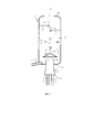
[0041] На фиг. 1 представлено упрощенное изображение продольного сечения системы согласно настоящей заявке, содержащей вертикально расположенную колонну с распылительным орошением, которая оборудована центральной трубой отработанного газа, расположенной вблизи и проникающей в нижний конец колонны с распылительным орошением, причем две трубы отработанного газа двигателей проникают в нижний конец центральной трубы отработанного газа, и при этом колонна с распылительным орошением содержит два распылительных устройства, распыляющих очищающую жидкость вверх, и два распылительных устройства, распыляющих очищающую жидкость вниз в колонне с распылительным орошением;[0041] FIG. 1 is a simplified longitudinal sectional view of a system according to the present application, comprising a vertically positioned spray column that is equipped with a central waste gas pipe located close to and penetrating into the lower end of the spray column, with two engine exhaust gas pipes penetrating the lower end of the central pipe. waste gas, and the spray column contains two spray devices that spray the cleaning liquid upward, and two spray devices, spray the cleaning liquid downward in the spray column;
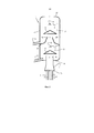
[0042] на фиг. 2 представлено упрощенное изображение продольного сечения системы согласно настоящей заявке, содержащей вертикально расположенную колонну с распылительным орошением с нижней и верхней очистительными камерами, в которой нижняя очистительная камера содержит центральную трубу отработанного газа, расположенную вблизи и проникающую в нижний конец колонны с распылительным орошением, причем две трубы отработанного газа двигателя проникают в нижний конец центральной трубы отработанного газа, где нижняя и верхняя очистительные камеры оборудованы распылительным соплом, которое выполнено с возможностью распыления очищающей жидкости в направлении вниз;[0042] in FIG. 2 is a simplified longitudinal sectional view of a system according to the present application, comprising a vertically arranged spray column with lower and upper purification chambers, in which the lower purification chamber contains a central waste gas pipe located near and penetrating into the lower end of the spray column, with two the exhaust gas pipes of the engine penetrate into the lower end of the central exhaust gas pipe, where the lower and upper cleaning chambers are equipped with a spray nozzle that is configured to spray the cleaning liquid in a downward direction;
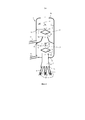
[0043] на фиг. 3 представлено упрощенное изображение продольного сечения скрубберной системы, содержащей вертикально расположенную колонну с распылительным орошением с верхней и нижней очистительными камерами, в которой нижняя очистительная камера содержит центральную трубу отработанного газа, расположенную вблизи и проникающую в нижний конец колонны с распылительным орошением, причем три трубы отработанного газа двигателей проникают в нижний конец центральной трубы отработанного газа и расположены под углом относительно нижнего конца, где нижняя и верхняя очистительная камера оборудованы двумя распылительными устройствами, из которых одно выполнено с возможностью распыления очищающей жидкости в направлении вверх, а другое выполнено с возможностью распыления очищающей жидкости в направлении вниз;[0043] in FIG. 3 is a simplified longitudinal sectional view of a scrubber system containing a vertically arranged spray column with upper and lower cleaning chambers, in which the lower cleaning chamber contains a central waste gas pipe located near and penetrating into the lower end of the spray irrigation column, with three waste tubes gas engines penetrate into the lower end of the central pipe of the exhaust gas and are located at an angle relative to the lower end, where the lower and upper cleaning chamber are equipped with two spray devices, one of which is configured to spray the cleaning liquid upward, and the other is configured to spray the cleaning liquid downward;
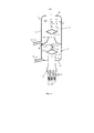
[0044] на фиг. 4 представлено упрощенное изображение продольного сечения скрубберной системы, содержащей вертикально расположенную колонну с распылительным орошением с верхней и нижней очистительными камерами, в которой нижняя очистительная камера содержит центральную трубу отработанного газа, расположенную вблизи и проникающую в нижний конец колонны с распылительным орошением, причем три вертикально расположенные трубы отработанного газа двигателей проникают в нижний конец центральной трубы отработанного газа, где нижняя очистительная камера оборудована тремя распылительными устройствами, которые выполнены с возможностью распыления очищающей жидкости в направлении вверх, и верхняя очистительная камера оборудована двумя распылительными устройствами, которые выполнены с возможностью распыления очищающей жидкости в направлении вниз;[0044] in FIG. 4 is a simplified longitudinal sectional view of a scrubber system comprising a vertically arranged spray column with upper and lower purification chambers, in which the lower purification chamber contains a central waste gas pipe located near and penetrating into the lower end of the spray column, three vertically arranged the exhaust gas pipes of the engines penetrate into the lower end of the central exhaust gas pipe, where the lower cleaning chamber is equipped with three spray devices that are configured to spray the cleaning liquid in an upward direction, and the upper cleaning chamber is equipped with two spray devices that are configured to spray the cleaning liquid into downward direction;
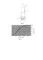
[0045] на фиг. 5 представлено трехмерное изображение трех труб отработанного газа двигателей, которые соединены с нижним концом центральной трубы отработанного газа;[0045] in FIG. 5 is a three-dimensional view of three exhaust gas pipes from engines which are connected to the lower end of a central exhaust gas pipe;
[0046] на фиг. 6а представлено распределение по размерам капель от спирального распылительного устройства, впрыскивающего 2180 литров воды в минуту при давлении 2 бар;[0046] in FIG. 6a shows the droplet size distribution from a spiral spray device injecting 2180 liters of water per minute at a pressure of 2 bar;
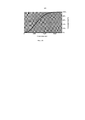
[0047] на фиг. 6b представлено распределение по размерам капель от спирального распылительного устройства, впрыскивающего 3380 литров воды в минуту при давлении 2 бар.[0047] in FIG. 6b shows the droplet size distribution from a spiral spray device injecting 3380 liters of water per minute at a pressure of 2 bar.
Подробное раскрытие настоящего изобретенияDetailed Disclosure of the Present Invention
[0048] Все различные варианты осуществления системы согласно настоящей заявке, которые представлены на фиг. 1-5, предусматривают колонну (1) с распылительным орошением для удаления SOx из отработанного газа, производимого двигателями (не представленными на фигурах), более конкретно, судовыми двигателями, которая выполнена с возможностью практически вертикального расположения. В своей простейшей форме колонна (1) с распылительным орошением состоит из цилиндра, имеющего внутреннее пространство (100). Колонна (1) с распылительным орошением также имеет нижний конец (1а) и верхний конец (1b) в своем установленном положении. Более конкретно, нижний конец (1а) находится на противоположной стороне относительно верхнего конца (1b) колонны (1) с распылительным орошением. Более конкретно, цилиндр имеет осевую симметрию относительно общей продольной оси. Целесообразным является выпуск (3) отработанного газа, коаксиально проходящий через верхний конец (1b) колонны (1) с распылительным орошением. У нижнего конца (1а) колонны (1) с распылительным орошением расположена центральная труба (7) для отработанного газа. Эта центральная труба (7) для отработанного газа имеет открытый ближний конец (7b), определяющий впуск (2) отработанного газа, и частично закрытый дальний конец (7а). Более конкретно, дальний конец (7а) центральной трубы (7) для отработанного газа расположен на противоположной стороне относительно ближнего конца (7b) центральной трубы (7) для отработанного газа. Центральная труба (7) для отработанного газа находится в соединении с возможностью переноса текучей среды с внутренним пространством (100) колонны (1) с распылительным орошением. Более конкретно, центральная труба (7) для отработанного газа проходит через нижний конец (1а) колонны (1) с распылительным орошением и переходит во внутреннее пространство (100) колонны (1) с распылительным орошением. Поперечное сечение центральной трубы (7) для отработанного газа может иметь любую форму. Однако преимущество имеет круглое или овальное поперечное сечение. Если поперечное сечение центральной трубы (7) для отработанного газа имеет форму многоугольника с углами между прилегающими стенками, в частности, прямыми и острыми углами, это может отрицательно повлиять на характеристики потока.[0048] All of the various embodiments of the system of this application that are illustrated in FIG. 1-5 provide a spray column (1) for removing SO x from exhaust gas produced by engines (not shown in the figures), more particularly marine engines, which is arranged to be substantially vertical. In its simplest form, the spray column (1) consists of a cylinder having an interior space (100). The spray column (1) also has a lower end (1a) and an upper end (1b) in their installed position. More specifically, the lower end (1a) is on the opposite side from the upper end (1b) of the spray column (1). More specifically, the cylinder is axially symmetrical about a common longitudinal axis. It is expedient to discharge (3) waste gas, passing coaxially through the upper end (1b) of the spray column (1). At the lower end (1a) of the spray column (1), there is a central waste gas pipe (7). This central exhaust gas pipe (7) has an open proximal end (7b) defining an exhaust gas inlet (2) and a partially closed distal end (7a). More specifically, the distal end (7a) of the central waste gas pipe (7) is located on the opposite side from the proximal end (7b) of the central waste gas pipe (7). The central waste gas pipe (7) is in fluid communication with the interior (100) of the spray column (1). More specifically, the central waste gas pipe (7) passes through the lower end (1a) of the spray column (1) and into the interior (100) of the spray column (1). The cross-section of the central waste gas pipe (7) can be of any shape. However, a circular or oval cross-section is advantageous. If the cross-section of the central flue gas pipe (7) is polygonal with angles between adjacent walls, in particular right and sharp corners, this can adversely affect the flow characteristics.
[0049] У дальнего конца (7а) центральной трубы (7) для отработанного газа по меньшей мере две трубы (6) отработанного газа двигателя, которые соединены с возможностью переноса текучей среды с двигателями, выпускающими отработанный газ, присоединены к колонне (1) с распылительным орошением. Указанные трубы (6) отработанного газа двигателя, таким образом, выполнены с возможностью перемещения отработанного газа, производимого двигателями, в колонну (1) с распылительным орошением через центральную трубу (7) для отработанного газа. Более конкретно, трубы (6) отработанного газа двигателя проходят через дальний конец (7а) центральной трубы (7) для отработанного газа и, таким образом, переходят во внутреннее пространство (100) колонны (1) с распылительным орошением. Однако они могут также находиться в соединении с дальним концом (7а) центральной трубы (7) для отработанного газа без прохождения через этот дальний конец (7а). Посредством присоединения труб (6) отработанного газа двигателя к центральной трубе (7) для отработанного газа скорость потока отработанного газа в колонне (1) с распылительным орошением снижается, что может упрощать желательный турбулентный поток отработанного газа через колонну (1) с распылительным орошением.[0049] At the distal end (7a) of the central exhaust gas pipe (7), at least two engine exhaust gas pipes (6), which are fluidly connected to exhaust gas engines, are connected to a column (1) with spray irrigation. Said engine exhaust gas pipes (6) are thus adapted to transfer the exhaust gas produced by the engines into the spray column (1) through the central waste gas pipe (7). More specifically, the engine exhaust pipes (6) pass through the distal end (7a) of the central exhaust gas pipe (7) and thus enter the interior (100) of the spray column (1). However, they can also be in communication with the distal end (7a) of the central waste gas pipe (7) without passing through this distal end (7a). By connecting the engine exhaust gas pipes (6) to the central exhaust gas pipe (7), the flow rate of the exhaust gas in the spray tower (1) is reduced, which can facilitate the desired turbulent flow of exhaust gas through the spray tower (1).
[0050] Данная центральная труба (7) для отработанного газа позволяет присоединять более чем два двигателя к колонне (1) с распылительным орошением. Более конкретно, возможно также присоединение 3, 4, 5 или 6 двигателей к центральной трубе (7) для отработанного газа. Является возможным присоединение одного двигателя к одной трубе (6) отработанного газа двигателя. Следовательно, можно присоединять 3, 4, 5 или 6 двигателей к центральной трубе (7) для отработанного газа через 3, 4, 5 или 6 труб (6) отработанного газа двигателя. На фиг. 3-5 три трубы (6) отработанного газа двигателей присоединены к центральной трубе (7) для отработанного газа, что позволяет присоединять три двигателя к колонне (1) с распылительным орошением через три трубы (6) отработанного газа двигателя, которые, в свою очередь, присоединены к центральной трубе (7) для отработанного газа.[0050] This central waste gas pipe (7) allows more than two motors to be connected to the spray column (1). More specifically, it is also possible to connect 3, 4, 5 or 6 motors to the central waste gas pipe (7). It is possible to connect one engine to one pipe (6) of the engine exhaust gas. Therefore, it is possible to connect 3, 4, 5 or 6 motors to the central exhaust gas pipe (7) via 3, 4, 5 or 6 engine exhaust pipes (6). FIG. 3-5, three engine exhaust gas pipes (6) are connected to a central exhaust gas pipe (7), which allows three engines to be connected to a spray column (1) through three engine exhaust gas pipes (6), which in turn connected to the central waste gas pipe (7).
[0051] Обратный поток отработанного газа в двигатель, который не находится в процессе работы, например, вследствие обслуживания, может быть предотвращен посредством клапана (15) отработанного газа в каждой из труб (6) отработанного газа двигателя (как представлено на фиг. 3 и 4).[0051] Backflow of exhaust gas to an engine that is not in operation, for example due to maintenance, can be prevented by an exhaust gas valve (15) in each of the engine exhaust pipes (6) (as shown in FIG. 3 and four).
[0052] Трубы (6) отработанного газа двигателя могут быть расположены практически вертикально, как представлено на фиг. 2 и 4. Указанное расположение будет обеспечивать минимальное противодавление. Однако когда клапаны (15) отработанного газа установлены в трубах (6) отработанного газа двигателя, должно присутствовать пространство для размещения указанных клапанов (15) отработанного газа, через которое в большинстве случаев трубы (6) отработанного газа двигателя должны проходить под углом по отношению к дальнему концу (7а) центральной трубы (7) для отработанного газа и отклоняться друг от друга, начиная у дальнего конца (7а), как можно видеть на фиг. 3, в результате чего возникает незначительно повышенное противодавление.[0052] The engine exhaust gas pipes (6) can be arranged substantially vertically as shown in FIG. 2 and 4. This arrangement will provide minimum back pressure. However, when the exhaust gas valves (15) are installed in the exhaust gas pipes (6) of the engine, there must be space for the said exhaust gas valves (15), through which in most cases the exhaust gas pipes (6) of the engine must pass at an angle with respect to the distal end (7a) of the central waste gas pipe (7) and deviate from each other, starting at the distal end (7a), as can be seen in FIG. 3, resulting in a slightly increased back pressure.
[0053] В колонне (1) с распылительным орошением общий поток отработанного газа перемещается через колонну (1) с распылительным орошением от впуска (2) отработанного газа до выпуска (3) отработанного газа и при этом вступает в контакт с потоком очищающей жидкости, которая перемещается в направлении, противоположном общему потоку отработанного газа. При упоминании в настоящем документе общий поток отработанного газа представляет собой среднее направление, по которому отработанный газ перемещается через колонну (1) с распылительным орошением. Даже если поток отработанного газа является турбулентным и в локальных областях может перемещаться в любом направлении, общий поток отработанного газа в целом перемещается вверх в вертикально расположенной колонне (1) с распылительным орошением от впуска (2) отработанного газа до выпуска (3) отработанного газа.[0053] In the spray column (1), the total waste gas stream moves through the spray column (1) from the waste gas inlet (2) to the waste gas outlet (3) and comes into contact with a stream of cleaning liquid, which moves in the opposite direction to the overall waste gas flow. When referred to herein, the total waste gas flow is the middle direction in which the waste gas travels through the spray column (1). Even if the waste gas flow is turbulent and can move in any direction in local areas, the overall waste gas flow as a whole moves upwardly in a vertically arranged spray column (1) from the waste gas inlet (2) to the waste gas outlet (3).
[0054] Для получения потока очищающей жидкости в направлении, противоположном общему потоку отработанного газа, в целях очистки потока отработанного газа для удаления SOx устанавливают одно или несколько распылительных устройств во внутреннем пространстве (100) колонны (1) с распылительным орошением. Присутствуют распылительные устройства (41), которые выполнены с возможностью распыления очищающей жидкости в направлении вниз, и распылительные устройства (42), которые выполнены с возможностью распыления очищающей жидкости в направлении вверх. В частности, распылительные устройства (41, 42) присутствуют в форме распылительных сопел (41, 42). Более конкретно, распылительное сопло (41, 42) установлено на инжекторной линии (4), как правило, у ее конца, и направлено вверх или вниз, чтобы распылять очищающую жидкость в направлении вверх или вниз, соответственно. Можно установить все распылительные устройства (41) в колонне (1) с распылительным орошением для распыления очищающей жидкости в направлении вниз (как представлено на фиг. 2), а также установить все распылительные устройства (42) для распыления очищающей жидкости в направлении вверх (не представлено на фигурах). Однако можно также установить некоторые распылительные устройства (41) для распыления очищающей жидкости в направлении вниз и установить некоторые распылительные устройства (42) для распыления очищающей жидкости в направлении вверх (как представлено на фиг. 1, 3 и 4).[0054] One or more spraying devices are installed in the interior space (100) of the spray column (1) in order to obtain a flow of cleaning liquid in the opposite direction to the overall flow of waste gas in order to clean the flow of waste gas to remove SO x. There are spray devices (41) that are configured to spray the cleaning liquid in a downward direction and spray devices (42) that are configured to spray the cleaning liquid in an upward direction. In particular, the spray devices (41, 42) are in the form of spray nozzles (41, 42). More specifically, the spray nozzle (41, 42) is mounted on the injection line (4), usually at its end, and is directed upward or downward to spray the cleaning liquid in an upward or downward direction, respectively. It is possible to install all spray devices (41) in the spray column (1) to spray the cleaning liquid downward (as shown in Fig. 2), and also install all the spray devices (42) to spray the cleaning liquid upward (not shown in the figures). However, it is also possible to install some spray devices (41) to spray the cleaning liquid downward and install some spray devices (42) to spray the cleaning liquid upward (as shown in FIGS. 1, 3 and 4).
[0055] Распылительные устройства (41, 42) создают падающие капельки очищающей жидкости (не представленные на фигурах). Поток очищающей жидкости может представлять собой любую жидкость на водной основе или водный раствор, включая, но не ограничиваясь этим, пресную воду, соленую воду и щелочной водный раствор. Для морских судов поток очищающей жидкости может целесообразно представлять собой соленую воду, в частности, морскую воду. Добавление щелочного водного раствора, содержащего растворенный MgO или Mg(OH)2, в очищающую жидкость может увеличивать способность абсорбции SOx. Такое увеличение абсорбционной способности является особенно важным, если очищающая жидкость рециркулирует обратно в колонну с распылительным орошением (система с замкнутым контуром). Это объясняется тем, что абсорбция SOx будет уменьшать рН и, таким образом, уменьшать способность последующей абсорбции дополнительного количества примесей SOx.[0055] Spraying devices (41, 42) create falling droplets of cleaning liquid (not shown in the figures). The stream of cleaning liquid can be any water-based liquid or aqueous solution, including, but not limited to, fresh water, salt water, and alkaline aqueous solution. For marine vessels, the stream of cleaning fluid may suitably be salt water, in particular seawater. Adding an alkaline aqueous solution containing dissolved MgO or Mg (OH) 2 to the cleaning liquid can increase the SO x absorption capacity. This increase in absorption capacity is especially important if the cleaning liquid is recirculated back to the spray column (closed loop system). This is because SO x absorption will lower the pH and thus reduce the ability to subsequently absorb additional SO x impurities.
[0056] Распылительные устройства (41, 42) могут представлять собой любой тип, например, распылительные сопла, содержащие простое отверстие или профилированное отверстие. В частности, распылительные устройства (41, 42) могут представлять собой распылительное сопло с отбойной поверхностью или плоское сопло с веерообразным распылением. В частности, часто оказывается желательным использование распылительного устройства, имеющего отбойную поверхность в форме спирали (спиральное распылительное устройство), которое производит распыление в форме сплошного конуса или в форме полого конуса. Сопло спиральной конструкции обычно производит капли меньшего размера, чем сопло нагнетательной конструкции завихряющего типа при данных значениях давлении и скорости потока. Эта спиральная конструкция может быть также более устойчивой к закупориванию вследствие большего свободного протока. Подходящие и часто желательные спиральный распылительные устройства могут обеспечивать распыление в форме сплошного конуса с каплями, имеющими распределение по размерам, которое представлено на фиг. 6а или 6b, или меньшие размеры, для впрыскивания 2180 литров воды в минуту или 3380 литров воды в минуту, соответственно, при давлении 2 бар.[0056] Spraying devices (41, 42) can be of any type, for example, spray nozzles containing a simple orifice or a profiled orifice. In particular, the spraying devices (41, 42) can be a baffled spray nozzle or a flat fan-shaped spray nozzle. In particular, it is often desirable to use a spray device having a spiral bump surface (spiral spray device) that sprays in a solid cone or hollow cone. A spiral nozzle typically produces smaller droplets than a swirl-type discharge nozzle at a given pressure and flow rate. This spiral design can also be more resistant to plugging due to the larger free flow. Suitable and often desirable spiral spray devices can provide a solid cone spray with droplets having a size distribution as shown in FIG. 6a or 6b, or smaller, for injecting 2180 liters of water per minute or 3380 liters of water per minute, respectively, at a pressure of 2 bar.
[0057] Распылительные устройства (41, 42), как правило, выполнены с возможностью обеспечения капелек очищающей жидкости в процессе эксплуатации, причем капельки, составляющие более чем 50% объема, имеют диаметр, составляющий от 0,35 мм до 4 мм, более конкретно от 0,5 до 2 мм и наиболее конкретно приблизительно 1 мм. При упоминании в настоящем документе диаметр капелек, также называемый размером капель, представляет собой средний диаметр по Заутеру. Он представляет собой диаметр частицы, у которой соотношение объема и площади поверхности является таким же, как для образца при полном распылении. Его вычисляют в результате деления куба среднеобъемного диаметра на квадрат среднеповерхностного диаметра. Как правило, средний диаметр по Заутеру составляет приблизительно 80% объемного медианного диаметра.[0057] The spraying devices (41, 42) are generally configured to provide droplets of cleaning liquid during use, the droplets constituting more than 50% of the volume have a diameter ranging from 0.35 mm to 4 mm, more particularly 0.5 to 2 mm, and most particularly about 1 mm. When referred to herein, the droplet diameter, also called droplet size, is the Sauter mean diameter. It is the diameter of a particle for which the ratio of volume to surface area is the same as for a fully sprayed sample. It is calculated by dividing the cube of the average volumetric diameter by the square of the average surface diameter. Typically, the Sauter median diameter is approximately 80% of the volume median diameter.
[0058] При упоминании в настоящем документе капли очищающей жидкости представляют собой частицы очищающей жидкости, имеющие достаточный размер, чтобы падать вниз в колонне с распылительным орошением в течение очистки отработанного газа. Достаточный размер будет зависеть от потока отработанного газа и температуры отработанного газа, и его может легко определить специалист в данной области техники. Такие капли очищающей жидкости будут падать в направлении, противоположном общему потоку отработанного газа. Капли очищающей жидкости могут испаряться, становясь мельче, и очищающая жидкость может даже полностью превращаться в пар в зависимости от нескольких параметров, таких как начальный размер капелек, температура отработанного газа и поток отработанного газа. При упоминании в настоящем документе капельки очищающей жидкости представляют собой частицы очищающей жидкости, имеющие недостаточный размер, чтобы падать вниз в колонне с распылительным орошением в течение очистки отработанного газа. Таким образом, капельки очищающей жидкости будут, в основном, перемещаться вместе с общим потоком отработанного газа. Капельки очищающей жидкости могут сталкиваться друг с другом и, таким образом, увеличиваться в размере, превращаясь в более крупные капли. Впрыскиваемый объем воды можно регулировать согласно нагрузке двигателя, чтобы оптимизировать эксплуатационные характеристики скруббера. Например, впрыскиваемый объем воды может находиться в диапазоне от 10000 до 15000 литров в минуту для колонны (1) с распылительным орошением, имеющей высоту от 10 до 15 метров и диаметр, составляющий приблизительно 3 метра, и очищающей 30 кг отработанного газа в секунду.[0058] As referred to herein, cleaning liquid droplets are cleaning liquid particles of a sufficient size to fall down in a spray column during waste gas cleaning. Sufficient size will depend on the flue gas flow and flue gas temperature and can be readily determined by one skilled in the art. Such droplets of cleaning liquid will fall in the opposite direction to the overall flow of the waste gas. The droplets of the cleaning liquid can evaporate, becoming finer, and the cleaning liquid can even completely vaporize, depending on several parameters such as the initial droplet size, flue gas temperature and flue gas flow. When referred to herein, cleaning liquid droplets are cleaning liquid particles that are not sized enough to fall down in a spray column during waste gas cleaning. Thus, the droplets of the cleaning liquid will generally move with the overall waste gas stream. Droplets of cleaning fluid can collide with each other and thus grow in size to become larger droplets. The volume of water injected can be adjusted according to the engine load to optimize the scrubber's performance. For example, the injected volume of water may be in the range of 10,000 to 15,000 liters per minute for a spray column (1) having a height of 10 to 15 meters and a diameter of approximately 3 meters and cleaning 30 kg of waste gas per second.
[0059] Может существовать колонна (1) с распылительным орошением согласно настоящей заявке, имеющая только одну очистительную камеру (13) (как можно видеть на фиг. 1), но колонна может также иметь множество очистительных камер (13, 14), как можно видеть на фиг. 2-4. В системе, которая представлена на фиг. 2-4, присутствуют две очистительные камеры (13, 14). Когда колонна (1) с распылительным орошением содержит два или более очистительные камеры (13, 14), они частично отделены друг от друга, но также частично соединены друг с другом с возможностью переноса текучей среды посредством соединения (9). Соединение (9) может, например, представлять собой коаксиальную конструкцию, перемещающую частично очищенный отработанный газ их нижней очистительной камеры (13) в верхнюю очистительную камеру (14).[0059] There may be a spray column (1) according to the present application having only one purification chamber (13) (as can be seen in FIG. 1), but the column may also have multiple purification chambers (13, 14), as possible see in FIG. 2-4. In the system shown in FIG. 2-4, there are two cleaning chambers (13, 14). When the spray column (1) contains two or more purification chambers (13, 14), they are partially separated from each other, but also partially connected to each other with the possibility of transferring fluid through the connection (9). The connection (9) can, for example, be a coaxial structure that moves the partially cleaned waste gas from the lower cleaning chamber (13) to the upper cleaning chamber (14).
[0060] Число распылительных устройств (41, 42) и направление, в котором они распыляют очищающую жидкость, могут изменяться в пределах одной очистительной камеры (13) или в пределах различных очистительных камер (13, 14). На фиг. 1, где колонна (1) с распылительным орошением имеет только одну очистительную камеру (13), присутствуют четыре распылительных устройства (41, 42), в том числе два верхних распылительных устройства (41), которые выполнены с возможностью распыления очищающей жидкости в направлении вниз, и два нижних распылительных устройства (42), которые выполнены с возможностью распыления очищающей жидкости в направлении вверх. На фиг. 2-4 колонна (1) с распылительным орошением имеет нижнюю и верхнюю очистительные камеры (13, 14). На фиг. 2 нижняя очистительная камера (13), а также верхняя очистительная камера (14) оборудована одним распылительным устройством (41), которое выполнено с возможностью распыления очищающей жидкости в направлении вниз. На фиг. 3 нижняя очистительная камера (13), а также верхняя очистительная камера (14) имеет два распылительных устройства (41, 42), в том числе одно распылительное устройство (41), которое выполнено с возможностью распыления очищающей жидкости в направлении вниз, и одно распылительное устройство (42), которое выполнено с возможностью распыления очищающей жидкости в направлении вверх. На фиг. 4 нижняя очистительная камера (13) оборудована тремя распылительными устройствами (42), из которых все выполнены с возможностью распыления очищающей жидкости в направлении вверх, в то время как верхняя очистительная камера (14) оборудована двумя распылительными устройствами (41), которые выполнены с возможностью распыления очищающей жидкости в направлении вниз.[0060] The number of spray devices (41, 42) and the direction in which they spray the cleaning liquid can vary within one cleaning chamber (13) or within different cleaning chambers (13, 14). FIG. 1, where the spray column (1) has only one cleaning chamber (13), there are four spray devices (41, 42), including two upper spray devices (41), which are configured to spray the cleaning liquid in the downward direction , and two lower spray devices (42), which are configured to spray the cleaning liquid in an upward direction. FIG. 2-4 column (1) with spray irrigation has lower and upper purification chambers (13, 14). FIG. 2, the lower cleaning chamber (13) as well as the upper cleaning chamber (14) are equipped with one spray device (41), which is configured to spray the cleaning liquid downward. FIG. 3, the lower cleaning chamber (13), as well as the upper cleaning chamber (14), have two spray devices (41, 42), including one spray device (41), which is configured to spray the cleaning liquid in the downward direction, and one spray a device (42) that is configured to spray the cleaning liquid upward. FIG. 4, the lower cleaning chamber (13) is equipped with three spray devices (42), all of which are configured to spray the cleaning liquid upward, while the upper cleaning chamber (14) is equipped with two spray devices (41), which are configured spraying the cleaning liquid downwards.
[0061] Кроме того, колонна (1) с распылительным орошением может быть оборудована одним или несколькими отклоняющими элементами (8), которые выполнены с возможностью уменьшения или в оптимальном случае предотвращения поступления очищающей жидкости в центральную трубу (7) для отработанного газа или поступления в соединение (9) между верхней и нижней очистительными камерами (13, 14) или, другими словами, в выпуск отработанного газа из нижней очистительной камеры (13), если он присутствует. Кроме того, отклоняющие элементы (8) могут направлять отработанный газ в направлении стенок колонны (1) с распылительным орошением и таким путем создавать турбулентный поток газа. Форма отклоняющих элементов (8) может также влиять на противодавление и может быть легко модифицирована соответствующим образом специалистом в данной области техники. Например, продольное сечение отклоняющих элементов (8) может иметь приблизительно ромбообразную форму или иметь любую другую форму, совместимую с низким противодавлением. Аналогичным образом, поперечное сечение отклоняющих элементов (8) может иметь круглую, овальную или любую другую форму, совместимую с низким противодавлением. Как правило, отклоняющие элементы (8) расположены ниже распылительного устройства (устройств) (41, 42).[0061] In addition, the spray column (1) can be equipped with one or more diverting elements (8), which are configured to reduce or optimally prevent the cleaning liquid from entering the central waste gas pipe (7) or entering connection (9) between the upper and lower cleaning chambers (13, 14) or, in other words, into the exhaust gas outlet from the lower cleaning chamber (13), if present. In addition, the deflectors (8) can direct the exhaust gas towards the walls of the spray column (1) and thus create a turbulent gas flow. The shape of the deflectors (8) can also affect the back pressure and can be easily modified accordingly by a person skilled in the art. For example, the longitudinal section of the deflecting elements (8) may be approximately rhomboid or any other shape compatible with low back pressure. Likewise, the cross-section of the deflectors (8) can be round, oval or any other shape that is compatible with low back pressure. Typically, the deflecting elements (8) are located below the spray device (s) (41, 42).
[0062] Для слива использованной очищающей жидкости из колонны (1) с распылительным орошением каждая очистительная камера (13, 14) имеет выпуск (5, 11) очищающей жидкости. Соединение (9) между верхней и нижней очистительными камерами (13, 14), как правило, имеет такую форму, которая обеспечивает, чтобы использованная очищающая жидкость легко направлялась в выпускные трубы (5, 11) очищающей жидкости для слива из колонны (1) с распылительным орошением. Когда присутствует одна очистительная камера (13), выпуск (5) очищающей жидкости, как правило, расположен в нижнем конце (1b) колонны (1) с распылительным орошением в целях оптимального слива использованной очищающей жидкости из колонны (1) с распылительным орошением. Если центральная труба (7) для отработанного газа проходит через нижний конец (1b) колонны (1) с распылительным орошением, как в случае системы, представленной на фиг. 1, выпуск (5) очищающей жидкости, как правило, расположен ниже ближнего конца (7b) этой центральной трубы (7) для отработанного газа. Когда колонна (1) с распылительным орошением имеет множество очистительных камер (13, 14), как в случае систем, представленных на фиг. 2-4, то в нижней очистительной камере (13) выпуск (5) очищающей жидкости также расположен в нижнем конце (1b) колонны (1) с распылительным орошением, а если центральная труба (7) для отработанного газа проходит через нижний конец (1b) колонны (1) с распылительным орошением, выпуск (5) очищающей жидкости расположен ниже ближнего конца (7b) центральной трубы (7) для отработанного газа. В верхней камере (14) выпуск очищающей жидкости (11) расположен на одной из боковых стенок (1с) колонны (1) с распылительным орошением выше нижнего конца (9b) соединения (9), но ниже открытого верхнего конца (9а) данного соединения (9). Это обеспечивает эффективный слив использованной очищающей жидкости из верхней очистительной камеры (14).[0062] To drain the used cleaning liquid from the spray column (1), each cleaning chamber (13, 14) has a cleaning liquid outlet (5, 11). The connection (9) between the upper and lower cleaning chambers (13, 14) is generally shaped so that the used cleaning liquid is easily directed into the cleaning liquid outlet pipes (5, 11) to drain from the column (1) with spray irrigation. When a single cleaning chamber (13) is present, the cleaning liquid outlet (5) is typically located at the lower end (1b) of the spray column (1) in order to optimally drain the used cleaning liquid from the spray column (1). If the central waste gas pipe (7) passes through the lower end (1b) of the spray column (1), as in the case of the system shown in FIG. 1, the outlet (5) of the cleaning liquid is generally located below the proximal end (7b) of this central waste gas pipe (7). When the spray column (1) has a plurality of purification chambers (13, 14), as in the case of the systems shown in FIG. 2-4, in the lower cleaning chamber (13), the outlet (5) of the cleaning liquid is also located at the lower end (1b) of the spray column (1), and if the central waste gas pipe (7) passes through the lower end (1b ) of the spray column (1), the cleaning liquid outlet (5) is located below the proximal end (7b) of the central waste gas pipe (7). In the upper chamber (14), the outlet of the cleaning liquid (11) is located on one of the side walls (1c) of the spray column (1) above the lower end (9b) of the connection (9), but below the open upper end (9a) of this connection ( 9). This ensures that the used cleaning fluid is effectively drained from the upper cleaning chamber (14).
[0063] Колонна с распылительным орошением может необязательно содержать сепаратор капелек (не представленный на фигурах), способный предотвращать выход капелек очищающей жидкости из колонна (1) с распылительным орошением вместе с очищенным отработанным газом. Сепаратор капелек может быть установлен вблизи выпуска (3) отработанного газа.[0063] The spray column may optionally comprise a droplet separator (not shown in the figures) capable of preventing droplets of cleaning liquid from escaping the spray column (1) along with the purified exhaust gas. A droplet separator can be installed close to the exhaust gas outlet (3).
[0064] Испытания системы согласно настоящей заявке, представленной на фиг. 4 и имеющей колонну (1) с распылительным орошением высотой 12 метров, продемонстрировали, что отработанный газ из нефтяного топлива, содержащего 3,3 мас. % серы, после очистки содержал лишь от 5 до 8 частей на миллион SO2. Результаты указанных испытаний были получены, когда температура отработанного газа в центральной трубе (7) для отработанного газа составляла вплоть до 280°С, и температура очищенного отработанного газа, выходящего из колонны (1) с распылительным орошением, на выпуске (3) отработанного газа составляла приблизительно 40°С.[0064] Testing the system according to the present application, shown in FIG. 4 and having a column (1) with spray irrigation with a height of 12 meters, demonstrated that the waste gas from fuel oil containing 3.3 wt. % sulfur, after purification contained only 5 to 8 ppm SO 2 . The results of these tests were obtained when the temperature of the flue gas in the central flue gas pipe (7) was up to 280 ° C, and the temperature of the cleaned flue gas leaving the spray column (1) at the flue gas outlet (3) was approximately 40 ° C.
Claims (36)
Applications Claiming Priority (3)
| Application Number | Priority Date | Filing Date | Title |
|---|---|---|---|
| EP16176030.1A EP3260187A1 (en) | 2016-06-23 | 2016-06-23 | System and method for reducing the amount of sulfur oxides in exhaust gas |
| EP16176030.1 | 2016-06-23 | ||
| PCT/EP2017/065484 WO2017220759A1 (en) | 2016-06-23 | 2017-06-23 | System and method for reducing the amount of sulfur oxides in exhaust gas |
Publications (1)
| Publication Number | Publication Date |
|---|---|
| RU2744407C1 true RU2744407C1 (en) | 2021-03-09 |
Family
ID=56235678
Family Applications (1)
| Application Number | Title | Priority Date | Filing Date |
|---|---|---|---|
| RU2018138239A RU2744407C1 (en) | 2016-06-23 | 2017-06-23 | System and the method for reducing the amount of sulfur oxides in exhaust gas |
Country Status (17)
| Country | Link |
|---|---|
| US (1) | US10563553B2 (en) |
| EP (2) | EP3260187A1 (en) |
| JP (1) | JP7015794B2 (en) |
| KR (1) | KR102377446B1 (en) |
| CN (1) | CN109152979A (en) |
| AR (1) | AR108816A1 (en) |
| AU (1) | AU2017281505B2 (en) |
| CA (1) | CA3014266A1 (en) |
| CL (1) | CL2018002916A1 (en) |
| IL (1) | IL262306B (en) |
| MX (1) | MX2018015024A (en) |
| MY (1) | MY189355A (en) |
| PH (1) | PH12018502462B1 (en) |
| RU (1) | RU2744407C1 (en) |
| SA (1) | SA518400586B1 (en) |
| SG (1) | SG11201807006RA (en) |
| WO (1) | WO2017220759A1 (en) |
Families Citing this family (34)
| Publication number | Priority date | Publication date | Assignee | Title |
|---|---|---|---|---|
| EP3243560A1 (en) | 2016-05-11 | 2017-11-15 | Yara Marine Technologies AS | Desulphurization of marine exhaust flue gas |
| JP6104491B1 (en) * | 2017-01-20 | 2017-03-29 | 三菱日立パワーシステムズ株式会社 | Ship desulfurization apparatus and ship equipped with the ship desulfurization apparatus |
| CN108479096B (en) * | 2018-02-12 | 2021-06-11 | 镇海石化工业贸易有限责任公司 | Circulating separation system and method for removing low-boiling-point organic matter monomer or solvent by using same |
| AT520534B1 (en) | 2018-04-19 | 2019-05-15 | Andritz Ag Maschf | Plant for the absorption of individual components from gases |
| CN108525496B (en) * | 2018-04-26 | 2020-12-15 | 江苏蓝电环保股份有限公司 | Sulfide purification treatment method for industrial waste gas |
| FR3086188B1 (en) * | 2018-09-26 | 2020-12-18 | Lab Sa | DEVICE FOR PROTECTING THE ADMISSION OF FUMES INTO A WASHER, AS WELL AS A PURIFICATION SYSTEM INCLUDING SUCH A PROTECTIVE DEVICE |
| GR1009733B (en) * | 2018-12-27 | 2020-05-15 | Δουσης, Ευαγγελος Γεωργιου | Exhaust gas desulfurization system installed on existing exhaust gas stack of a marine vessel |
| KR102181593B1 (en) * | 2019-04-16 | 2020-11-23 | 주식회사 시뮬레이션테크 | Scrubber Having Compact Structure For Ship |
| CN110007642B (en) * | 2019-04-29 | 2021-10-08 | 南通航海机械集团有限公司 | Automatic control method for ship waste gas cleaning high-flow seawater pump set |
| US11806679B2 (en) | 2019-07-23 | 2023-11-07 | Nanomist Technologies Co., Ltd. | Dissolution method |
| CN112403204A (en) * | 2019-08-22 | 2021-02-26 | 中国船舶重工集团公司第七一一研究所 | Compact marine I type scrubbing tower |
| FR3100320B1 (en) * | 2019-09-02 | 2022-02-18 | Air Liquide | Distribution device for a gas/liquid separation column |
| CN110433645A (en) * | 2019-09-09 | 2019-11-12 | 中船动力研究院有限公司 | A kind of flue gas desulfurization device |
| KR102605020B1 (en) * | 2019-10-31 | 2023-11-22 | 삼성중공업 주식회사 | Scrubber |
| CN110743366A (en) * | 2019-11-25 | 2020-02-04 | 北京航天三发高科技有限公司 | Engine test bed tail gas treatment system and use method thereof |
| FI128639B (en) * | 2019-12-20 | 2020-09-15 | Valmet Technologies Oy | Scrubber for exhaust gas cleaning |
| GR1009967B (en) * | 2020-01-23 | 2021-03-30 | Δουσης, Ευαγγελος Γεωργιου | Method of converting an existing ship' s chimney to an exhaust desulphurisation system |
| AT523153B1 (en) * | 2020-02-06 | 2021-06-15 | Avl List Gmbh | WET WASHER FOR GASES |
| AT523037B1 (en) * | 2020-02-07 | 2021-05-15 | Avl List Gmbh | WET WASHER FOR GASES |
| CN111256158B (en) * | 2020-03-17 | 2020-12-29 | 新昌县哈坎机械配件厂 | Building of environmental protection pipe of discharging fume |
| GB202003883D0 (en) * | 2020-03-18 | 2020-05-06 | Givaudan Sa | Consumer product |
| EP3906993A1 (en) * | 2020-05-05 | 2021-11-10 | Yara Marine Technologies AS | Wet inline scrubber with a side inlet for reducing the amount of sox in an exhaust gas produced by one or more engines of a marine vessel |
| CN111672304B (en) * | 2020-06-22 | 2022-07-12 | 扬州中康环保设备有限公司 | Even high-efficient acid mist purification tower of gas distribution |
| CN113877359A (en) * | 2020-07-02 | 2022-01-04 | 苏州迈莱柏系统工程有限公司 | Waste gas treatment system for laboratory |
| FR3112084B1 (en) * | 2020-07-06 | 2022-09-02 | Lab Sa | Installation and process for the wet purification of exhaust fumes from an engine of a marine vessel |
| CN111841255A (en) * | 2020-07-28 | 2020-10-30 | 高京拴 | Flue gas desulfurization device for environment-friendly production |
| KR102230166B1 (en) * | 2020-08-14 | 2021-03-22 | 인지이엔티 주식회사 | Apparatus for cleaning exhaust gas |
| CN112090266A (en) * | 2020-09-11 | 2020-12-18 | 北京清新环境技术股份有限公司 | Wet desulphurization device |
| CN112495098A (en) * | 2020-12-08 | 2021-03-16 | 呼伦贝尔东北阜丰生物科技有限公司 | Pipe bundle waste gas peculiar smell and dust comprehensive treatment device and application |
| CN112691528A (en) * | 2020-12-28 | 2021-04-23 | 厦门钨业股份有限公司 | Acid waste gas treatment system |
| CN112628782B (en) * | 2021-01-12 | 2023-06-23 | 辽宁科技学院 | Industrial flue gas desulfurization dust removal device and implementation method thereof |
| CN114704352B (en) * | 2022-03-24 | 2022-09-27 | 青州市春晖科技发展有限公司 | Diesel generator tail gas treatment device and treatment method thereof |
| CN114733338A (en) * | 2022-04-27 | 2022-07-12 | 江苏钜联环境技术有限公司 | Ternary lithium cell discharges waste gas and administers and uses high-efficient spraying system |
| CN116272319A (en) * | 2023-03-27 | 2023-06-23 | 江苏民生重工有限公司 | High-efficiency energy-saving tail gas washing tower |
Citations (4)
| Publication number | Priority date | Publication date | Assignee | Title |
|---|---|---|---|---|
| WO2006048506A1 (en) * | 2004-11-01 | 2006-05-11 | Kvaerner Power Oy | Method and scrubber for scrubbing flue gas flows |
| RU2289704C2 (en) * | 2001-03-14 | 2006-12-20 | Мариофф Корпорейшн Ой | Method of cleaning exhaust gases of internal combustion engine and device for delivering humid air into engine |
| RU2442637C2 (en) * | 2006-09-05 | 2012-02-20 | Клуе Ас | Outgoing gases desulphuration |
| US20160016109A1 (en) * | 2013-02-22 | 2016-01-21 | Marine Global Holding As | Marine exhaust gas scrubber |
Family Cites Families (15)
| Publication number | Priority date | Publication date | Assignee | Title |
|---|---|---|---|---|
| JPS6328823U (en) * | 1986-08-08 | 1988-02-25 | ||
| US6644024B1 (en) * | 2002-04-22 | 2003-11-11 | Brunswick Corporation | Exhaust system for a marine engine |
| FI20065330L (en) | 2006-05-16 | 2007-11-17 | Kvaerner Power Oy | Method and apparatus for reducing sulfur dioxide emissions from a marine engine |
| JP2009018290A (en) * | 2007-07-13 | 2009-01-29 | Ebara Corp | Exhaust gas washing device |
| JP2009052440A (en) * | 2007-08-24 | 2009-03-12 | Hitachi Plant Technologies Ltd | Marine exhaust gas treatment device |
| US20120090304A1 (en) * | 2010-10-19 | 2012-04-19 | Kotrba Adam J | Multiple Flow Path Exhaust Treatment System |
| JP2012180772A (en) | 2011-02-28 | 2012-09-20 | Mitsubishi Heavy Ind Ltd | Propulsion system, ship with the same, and method of controlling the same |
| EP2852452B1 (en) * | 2012-01-12 | 2016-08-31 | Wärtsilä Moss AS | Bottom-up scrubber |
| US20130228073A1 (en) * | 2012-03-05 | 2013-09-05 | Ronald G. Patterson | Methods and apparatuses for cooling and scrubbing diesel exhaust gases on a ship |
| KR101431077B1 (en) * | 2013-04-22 | 2014-08-21 | (주) 세아그린텍 | Exhaust gas cleaning system in marine diesel engines |
| JP6313945B2 (en) | 2013-09-30 | 2018-04-18 | 三菱日立パワーシステムズ株式会社 | Air diffuser for seawater desulfurization, seawater desulfurizer equipped with the same, and water quality improvement method |
| JP6444329B2 (en) * | 2016-03-24 | 2018-12-26 | ヤンマー株式会社 | Catalytic reactor and ship equipped with the same. |
| EP3243560A1 (en) | 2016-05-11 | 2017-11-15 | Yara Marine Technologies AS | Desulphurization of marine exhaust flue gas |
| US20190063298A1 (en) * | 2017-08-29 | 2019-02-28 | Caterpillar Inc. | Aftertreatment system |
| KR101940604B1 (en) * | 2018-09-03 | 2019-01-21 | 하이에어코리아 주식회사 | Wet Scrubber for Ship and Absorption Tower with Complex type Washwater Spray System |
-
2016
- 2016-06-23 EP EP16176030.1A patent/EP3260187A1/en not_active Withdrawn
-
2017
- 2017-06-19 AR ARP170101683A patent/AR108816A1/en active IP Right Grant
- 2017-06-23 SG SG11201807006RA patent/SG11201807006RA/en unknown
- 2017-06-23 MY MYPI2018002572A patent/MY189355A/en unknown
- 2017-06-23 RU RU2018138239A patent/RU2744407C1/en active
- 2017-06-23 MX MX2018015024A patent/MX2018015024A/en unknown
- 2017-06-23 WO PCT/EP2017/065484 patent/WO2017220759A1/en active Application Filing
- 2017-06-23 US US16/078,066 patent/US10563553B2/en active Active
- 2017-06-23 CN CN201780020263.0A patent/CN109152979A/en active Pending
- 2017-06-23 KR KR1020187029142A patent/KR102377446B1/en active IP Right Grant
- 2017-06-23 CA CA3014266A patent/CA3014266A1/en active Pending
- 2017-06-23 EP EP17736893.3A patent/EP3474968A1/en active Pending
- 2017-06-23 JP JP2018560898A patent/JP7015794B2/en active Active
- 2017-06-23 AU AU2017281505A patent/AU2017281505B2/en not_active Ceased
-
2018
- 2018-10-11 IL IL262306A patent/IL262306B/en unknown
- 2018-10-12 CL CL2018002916A patent/CL2018002916A1/en unknown
- 2018-11-23 PH PH12018502462A patent/PH12018502462B1/en unknown
- 2018-12-04 SA SA518400586A patent/SA518400586B1/en unknown
Patent Citations (4)
| Publication number | Priority date | Publication date | Assignee | Title |
|---|---|---|---|---|
| RU2289704C2 (en) * | 2001-03-14 | 2006-12-20 | Мариофф Корпорейшн Ой | Method of cleaning exhaust gases of internal combustion engine and device for delivering humid air into engine |
| WO2006048506A1 (en) * | 2004-11-01 | 2006-05-11 | Kvaerner Power Oy | Method and scrubber for scrubbing flue gas flows |
| RU2442637C2 (en) * | 2006-09-05 | 2012-02-20 | Клуе Ас | Outgoing gases desulphuration |
| US20160016109A1 (en) * | 2013-02-22 | 2016-01-21 | Marine Global Holding As | Marine exhaust gas scrubber |
Also Published As
| Publication number | Publication date |
|---|---|
| AU2017281505B2 (en) | 2022-07-07 |
| KR20190021196A (en) | 2019-03-05 |
| EP3260187A1 (en) | 2017-12-27 |
| WO2017220759A1 (en) | 2017-12-28 |
| JP2019521841A (en) | 2019-08-08 |
| CL2018002916A1 (en) | 2019-01-11 |
| KR102377446B1 (en) | 2022-03-23 |
| PH12018502462A1 (en) | 2019-09-16 |
| AU2017281505A1 (en) | 2018-11-15 |
| IL262306A (en) | 2018-11-29 |
| CN109152979A (en) | 2019-01-04 |
| US10563553B2 (en) | 2020-02-18 |
| AR108816A1 (en) | 2018-09-26 |
| JP7015794B2 (en) | 2022-02-15 |
| EP3474968A1 (en) | 2019-05-01 |
| SG11201807006RA (en) | 2018-09-27 |
| MY189355A (en) | 2022-02-07 |
| MX2018015024A (en) | 2019-08-14 |
| SA518400586B1 (en) | 2022-04-19 |
| CA3014266A1 (en) | 2017-12-28 |
| US20190107021A1 (en) | 2019-04-11 |
| PH12018502462B1 (en) | 2019-09-16 |
| IL262306B (en) | 2022-03-01 |
Similar Documents
| Publication | Publication Date | Title |
|---|---|---|
| RU2744407C1 (en) | System and the method for reducing the amount of sulfur oxides in exhaust gas | |
| AU2014220617B2 (en) | Marine exhaust gas scrubber | |
| KR101938149B1 (en) | An Apparatus for Exhaust Gas Treatment Having Diffusing Means | |
| KR101431077B1 (en) | Exhaust gas cleaning system in marine diesel engines | |
| KR20150024071A (en) | Exhaust gas desulfurization apparatus for marine diesel engines | |
| KR20190061434A (en) | Exhaust gas scrubber including mixing means | |
| KR101980883B1 (en) | An Apparatus for Exhaust Gas Treatment Having a Muti Spray Structure | |
| KR20180125120A (en) | An Apparatus for Exhaust Gas Treatment Having Improved Space Efficiency and Removal Efficiency of Harmful Substances and a Method thereof | |
| KR20180125119A (en) | An Apparatus for Exhaust Gas Treatment Having Improved Space Efficiency and Removal Efficiency of Harmful Substances and a Method thereof | |
| NZ747656A (en) | System and method for reducing the amount of sulfur oxides in exhaust gas | |
| KR101951226B1 (en) | An Apparatus for Exhaust Gas Treatment Having a Packing Support Means Capable of Diffusing | |
| KR101959406B1 (en) | An Apparatus for Exhaust Gas Treatment Having a Drop Separating Means | |
| KR20180127581A (en) | A Hybrid Type Exhaust Gas Treatment System Having Improved Space Efficiency | |
| KR102232057B1 (en) | Exhaust Gas Treatment Equipment Including Multi Diffusion Means | |
| KR102232059B1 (en) | Exhaust Gas Treatment Equipment With Reduced Pressure Loss and Improved Diffusion And Mixing performance | |
| KR101964959B1 (en) | A Hybrid Type Exhaust Gas Treatment System for Automatic Control on Supply Mode of Scrubbing Solution Based on the Location Information and a Method thereof | |
| KR20210044622A (en) | Exhaust Gas Treatment System | |
| KR20180127583A (en) | An Exhaust Gas Treatment System Having Backflow Prevention Means |