RU2742083C2 - Multilayer glazing comprising an embedded component, and use thereof - Google Patents
Multilayer glazing comprising an embedded component, and use thereof Download PDFInfo
- Publication number
- RU2742083C2 RU2742083C2 RU2018141384A RU2018141384A RU2742083C2 RU 2742083 C2 RU2742083 C2 RU 2742083C2 RU 2018141384 A RU2018141384 A RU 2018141384A RU 2018141384 A RU2018141384 A RU 2018141384A RU 2742083 C2 RU2742083 C2 RU 2742083C2
- Authority
- RU
- Russia
- Prior art keywords
- glazing
- pvb
- glass
- component
- sheet
- Prior art date
Links
Images


Classifications
-
- B—PERFORMING OPERATIONS; TRANSPORTING
- B32—LAYERED PRODUCTS
- B32B—LAYERED PRODUCTS, i.e. PRODUCTS BUILT-UP OF STRATA OF FLAT OR NON-FLAT, e.g. CELLULAR OR HONEYCOMB, FORM
- B32B17/00—Layered products essentially comprising sheet glass, or glass, slag, or like fibres
- B32B17/06—Layered products essentially comprising sheet glass, or glass, slag, or like fibres comprising glass as the main or only constituent of a layer, next to another layer of a specific material
- B32B17/10—Layered products essentially comprising sheet glass, or glass, slag, or like fibres comprising glass as the main or only constituent of a layer, next to another layer of a specific material of synthetic resin
- B32B17/10005—Layered products essentially comprising sheet glass, or glass, slag, or like fibres comprising glass as the main or only constituent of a layer, next to another layer of a specific material of synthetic resin laminated safety glass or glazing
- B32B17/10807—Making laminated safety glass or glazing; Apparatus therefor
- B32B17/10816—Making laminated safety glass or glazing; Apparatus therefor by pressing
- B32B17/10871—Making laminated safety glass or glazing; Apparatus therefor by pressing in combination with particular heat treatment
-
- C—CHEMISTRY; METALLURGY
- C03—GLASS; MINERAL OR SLAG WOOL
- C03C—CHEMICAL COMPOSITION OF GLASSES, GLAZES OR VITREOUS ENAMELS; SURFACE TREATMENT OF GLASS; SURFACE TREATMENT OF FIBRES OR FILAMENTS MADE FROM GLASS, MINERALS OR SLAGS; JOINING GLASS TO GLASS OR OTHER MATERIALS
- C03C27/00—Joining pieces of glass to pieces of other inorganic material; Joining glass to glass other than by fusing
- C03C27/06—Joining glass to glass by processes other than fusing
-
- B—PERFORMING OPERATIONS; TRANSPORTING
- B32—LAYERED PRODUCTS
- B32B—LAYERED PRODUCTS, i.e. PRODUCTS BUILT-UP OF STRATA OF FLAT OR NON-FLAT, e.g. CELLULAR OR HONEYCOMB, FORM
- B32B17/00—Layered products essentially comprising sheet glass, or glass, slag, or like fibres
- B32B17/06—Layered products essentially comprising sheet glass, or glass, slag, or like fibres comprising glass as the main or only constituent of a layer, next to another layer of a specific material
- B32B17/10—Layered products essentially comprising sheet glass, or glass, slag, or like fibres comprising glass as the main or only constituent of a layer, next to another layer of a specific material of synthetic resin
- B32B17/10005—Layered products essentially comprising sheet glass, or glass, slag, or like fibres comprising glass as the main or only constituent of a layer, next to another layer of a specific material of synthetic resin laminated safety glass or glazing
- B32B17/10009—Layered products essentially comprising sheet glass, or glass, slag, or like fibres comprising glass as the main or only constituent of a layer, next to another layer of a specific material of synthetic resin laminated safety glass or glazing characterized by the number, the constitution or treatment of glass sheets
- B32B17/10036—Layered products essentially comprising sheet glass, or glass, slag, or like fibres comprising glass as the main or only constituent of a layer, next to another layer of a specific material of synthetic resin laminated safety glass or glazing characterized by the number, the constitution or treatment of glass sheets comprising two outer glass sheets
-
- B—PERFORMING OPERATIONS; TRANSPORTING
- B32—LAYERED PRODUCTS
- B32B—LAYERED PRODUCTS, i.e. PRODUCTS BUILT-UP OF STRATA OF FLAT OR NON-FLAT, e.g. CELLULAR OR HONEYCOMB, FORM
- B32B17/00—Layered products essentially comprising sheet glass, or glass, slag, or like fibres
- B32B17/06—Layered products essentially comprising sheet glass, or glass, slag, or like fibres comprising glass as the main or only constituent of a layer, next to another layer of a specific material
- B32B17/10—Layered products essentially comprising sheet glass, or glass, slag, or like fibres comprising glass as the main or only constituent of a layer, next to another layer of a specific material of synthetic resin
- B32B17/10005—Layered products essentially comprising sheet glass, or glass, slag, or like fibres comprising glass as the main or only constituent of a layer, next to another layer of a specific material of synthetic resin laminated safety glass or glazing
- B32B17/10165—Functional features of the laminated safety glass or glazing
- B32B17/10541—Functional features of the laminated safety glass or glazing comprising a light source or a light guide
-
- B—PERFORMING OPERATIONS; TRANSPORTING
- B32—LAYERED PRODUCTS
- B32B—LAYERED PRODUCTS, i.e. PRODUCTS BUILT-UP OF STRATA OF FLAT OR NON-FLAT, e.g. CELLULAR OR HONEYCOMB, FORM
- B32B17/00—Layered products essentially comprising sheet glass, or glass, slag, or like fibres
- B32B17/06—Layered products essentially comprising sheet glass, or glass, slag, or like fibres comprising glass as the main or only constituent of a layer, next to another layer of a specific material
- B32B17/10—Layered products essentially comprising sheet glass, or glass, slag, or like fibres comprising glass as the main or only constituent of a layer, next to another layer of a specific material of synthetic resin
- B32B17/10005—Layered products essentially comprising sheet glass, or glass, slag, or like fibres comprising glass as the main or only constituent of a layer, next to another layer of a specific material of synthetic resin laminated safety glass or glazing
- B32B17/1055—Layered products essentially comprising sheet glass, or glass, slag, or like fibres comprising glass as the main or only constituent of a layer, next to another layer of a specific material of synthetic resin laminated safety glass or glazing characterized by the resin layer, i.e. interlayer
- B32B17/10761—Layered products essentially comprising sheet glass, or glass, slag, or like fibres comprising glass as the main or only constituent of a layer, next to another layer of a specific material of synthetic resin laminated safety glass or glazing characterized by the resin layer, i.e. interlayer containing vinyl acetal
-
- B—PERFORMING OPERATIONS; TRANSPORTING
- B32—LAYERED PRODUCTS
- B32B—LAYERED PRODUCTS, i.e. PRODUCTS BUILT-UP OF STRATA OF FLAT OR NON-FLAT, e.g. CELLULAR OR HONEYCOMB, FORM
- B32B7/00—Layered products characterised by the relation between layers; Layered products characterised by the relative orientation of features between layers, or by the relative values of a measurable parameter between layers, i.e. products comprising layers having different physical, chemical or physicochemical properties; Layered products characterised by the interconnection of layers
- B32B7/04—Interconnection of layers
- B32B7/12—Interconnection of layers using interposed adhesives or interposed materials with bonding properties
-
- B—PERFORMING OPERATIONS; TRANSPORTING
- B60—VEHICLES IN GENERAL
- B60Q—ARRANGEMENT OF SIGNALLING OR LIGHTING DEVICES, THE MOUNTING OR SUPPORTING THEREOF OR CIRCUITS THEREFOR, FOR VEHICLES IN GENERAL
- B60Q1/00—Arrangement of optical signalling or lighting devices, the mounting or supporting thereof or circuits therefor
- B60Q1/0088—Details of electrical connections
- B60Q1/0094—Arrangement of electronic circuits separated from the light source, e.g. mounting of housings for starter circuits for discharge lamps
-
- B—PERFORMING OPERATIONS; TRANSPORTING
- B60—VEHICLES IN GENERAL
- B60Q—ARRANGEMENT OF SIGNALLING OR LIGHTING DEVICES, THE MOUNTING OR SUPPORTING THEREOF OR CIRCUITS THEREFOR, FOR VEHICLES IN GENERAL
- B60Q1/00—Arrangement of optical signalling or lighting devices, the mounting or supporting thereof or circuits therefor
- B60Q1/02—Arrangement of optical signalling or lighting devices, the mounting or supporting thereof or circuits therefor the devices being primarily intended to illuminate the way ahead or to illuminate other areas of way or environments
-
- B—PERFORMING OPERATIONS; TRANSPORTING
- B60—VEHICLES IN GENERAL
- B60Q—ARRANGEMENT OF SIGNALLING OR LIGHTING DEVICES, THE MOUNTING OR SUPPORTING THEREOF OR CIRCUITS THEREFOR, FOR VEHICLES IN GENERAL
- B60Q1/00—Arrangement of optical signalling or lighting devices, the mounting or supporting thereof or circuits therefor
- B60Q1/26—Arrangement of optical signalling or lighting devices, the mounting or supporting thereof or circuits therefor the devices being primarily intended to indicate the vehicle, or parts thereof, or to give signals, to other traffic
- B60Q1/2661—Arrangement of optical signalling or lighting devices, the mounting or supporting thereof or circuits therefor the devices being primarily intended to indicate the vehicle, or parts thereof, or to give signals, to other traffic mounted on parts having other functions
- B60Q1/268—Arrangement of optical signalling or lighting devices, the mounting or supporting thereof or circuits therefor the devices being primarily intended to indicate the vehicle, or parts thereof, or to give signals, to other traffic mounted on parts having other functions on windscreens or windows
-
- C—CHEMISTRY; METALLURGY
- C03—GLASS; MINERAL OR SLAG WOOL
- C03C—CHEMICAL COMPOSITION OF GLASSES, GLAZES OR VITREOUS ENAMELS; SURFACE TREATMENT OF GLASS; SURFACE TREATMENT OF FIBRES OR FILAMENTS MADE FROM GLASS, MINERALS OR SLAGS; JOINING GLASS TO GLASS OR OTHER MATERIALS
- C03C27/00—Joining pieces of glass to pieces of other inorganic material; Joining glass to glass other than by fusing
- C03C27/06—Joining glass to glass by processes other than fusing
- C03C27/10—Joining glass to glass by processes other than fusing with the aid of adhesive specially adapted for that purpose
-
- B—PERFORMING OPERATIONS; TRANSPORTING
- B32—LAYERED PRODUCTS
- B32B—LAYERED PRODUCTS, i.e. PRODUCTS BUILT-UP OF STRATA OF FLAT OR NON-FLAT, e.g. CELLULAR OR HONEYCOMB, FORM
- B32B2307/00—Properties of the layers or laminate
- B32B2307/40—Properties of the layers or laminate having particular optical properties
- B32B2307/412—Transparent
-
- B—PERFORMING OPERATIONS; TRANSPORTING
- B32—LAYERED PRODUCTS
- B32B—LAYERED PRODUCTS, i.e. PRODUCTS BUILT-UP OF STRATA OF FLAT OR NON-FLAT, e.g. CELLULAR OR HONEYCOMB, FORM
- B32B2307/00—Properties of the layers or laminate
- B32B2307/40—Properties of the layers or laminate having particular optical properties
- B32B2307/416—Reflective
-
- B—PERFORMING OPERATIONS; TRANSPORTING
- B32—LAYERED PRODUCTS
- B32B—LAYERED PRODUCTS, i.e. PRODUCTS BUILT-UP OF STRATA OF FLAT OR NON-FLAT, e.g. CELLULAR OR HONEYCOMB, FORM
- B32B2551/00—Optical elements
- B32B2551/08—Mirrors
-
- B—PERFORMING OPERATIONS; TRANSPORTING
- B32—LAYERED PRODUCTS
- B32B—LAYERED PRODUCTS, i.e. PRODUCTS BUILT-UP OF STRATA OF FLAT OR NON-FLAT, e.g. CELLULAR OR HONEYCOMB, FORM
- B32B2605/00—Vehicles
-
- B—PERFORMING OPERATIONS; TRANSPORTING
- B32—LAYERED PRODUCTS
- B32B—LAYERED PRODUCTS, i.e. PRODUCTS BUILT-UP OF STRATA OF FLAT OR NON-FLAT, e.g. CELLULAR OR HONEYCOMB, FORM
- B32B2605/00—Vehicles
- B32B2605/006—Transparent parts other than made from inorganic glass, e.g. polycarbonate glazings
-
- B—PERFORMING OPERATIONS; TRANSPORTING
- B32—LAYERED PRODUCTS
- B32B—LAYERED PRODUCTS, i.e. PRODUCTS BUILT-UP OF STRATA OF FLAT OR NON-FLAT, e.g. CELLULAR OR HONEYCOMB, FORM
- B32B37/00—Methods or apparatus for laminating, e.g. by curing or by ultrasonic bonding
- B32B37/14—Methods or apparatus for laminating, e.g. by curing or by ultrasonic bonding characterised by the properties of the layers
- B32B37/16—Methods or apparatus for laminating, e.g. by curing or by ultrasonic bonding characterised by the properties of the layers with all layers existing as coherent layers before laminating
- B32B37/18—Methods or apparatus for laminating, e.g. by curing or by ultrasonic bonding characterised by the properties of the layers with all layers existing as coherent layers before laminating involving the assembly of discrete sheets or panels only
- B32B37/182—Methods or apparatus for laminating, e.g. by curing or by ultrasonic bonding characterised by the properties of the layers with all layers existing as coherent layers before laminating involving the assembly of discrete sheets or panels only one or more of the layers being plastic
Landscapes
- Engineering & Computer Science (AREA)
- Chemical & Material Sciences (AREA)
- Mechanical Engineering (AREA)
- Materials Engineering (AREA)
- Life Sciences & Earth Sciences (AREA)
- Chemical Kinetics & Catalysis (AREA)
- General Chemical & Material Sciences (AREA)
- Geochemistry & Mineralogy (AREA)
- Ceramic Engineering (AREA)
- Organic Chemistry (AREA)
- Physics & Mathematics (AREA)
- Thermal Sciences (AREA)
- Joining Of Glass To Other Materials (AREA)
- Securing Of Glass Panes Or The Like (AREA)
- Automobile Manufacture Line, Endless Track Vehicle, Trailer (AREA)
- Laminated Bodies (AREA)
Abstract
Description
Настоящее изобретение относится к области гнутого многослойного остекления, в частности, для применения в области автомобилестроения, где желательно встраивать компоненты в промежуточный лист адгезива (такого как поливинилбутираль, PVB), который проложен между двумя стеклянными листами.The present invention relates to the field of curved laminated glazing, in particular for automotive applications where it is desirable to embed components in an intermediate adhesive sheet (such as polyvinyl butyral, PVB) that is sandwiched between two glass sheets.
В настоящее время изготовителями стекла считается очень сложным введение компонентов, имеющих значительную толщину и значительную площадь, а именно, толщину обычно больше 0,2 мм и поперечные размеры больше 5 мм.At present, it is considered very difficult by glass manufacturers to introduce components having a significant thickness and a significant area, namely, the thickness is usually greater than 0.2 mm and the transverse dimensions are greater than 5 mm.
В частности, такой компонент, если его поместить непосредственно между двумя стеклянными листами, будет создавать дополнительный объем. Кроме того, известно, что в процессе сборки и автоклавирования PVB с трудом течет на расстояния более нескольких миллиметров. Кроме того, дополнительный объем, занимаемый компонентом, приведет к локальному утолщению стекла и к деформации внутреннего и наружного стеклянных листов изделия. Соответственно, могут возникнуть различные нежелательные явления:In particular, such a component, if placed directly between two glass sheets, will create additional volume. In addition, PVB is known to flow with difficulty over distances of more than a few millimeters during assembly and autoclaving. In addition, the additional volume occupied by the component will lead to localized glass thickening and deformation of the inner and outer glass sheets of the product. Accordingly, various undesirable phenomena may occur:
- чрезмерная деформация обоих стеклянных листов может создать чрезмерно высокие локальные растягивающее напряжения и привести к поломке одного из них;- excessive deformation of both glass sheets can create excessively high local tensile stresses and lead to breakage of one of them;
- вокруг компонента, вставленного в остекление, может произойти образование пузырей из-за низкого локального давления в PVB; это низкое давление является следствием деформации остекления из-за объема компонента и из-за свободного объема вокруг него, этот объем заполняется лишь частично из-за недостаточного течения PVB во время операций сборки и автоклавирования; отсутствие материала PVB или его низкое парциальное давление в материале способствует образованию пузырей вследствие улетучивания маленьких молекул, присутствующих в PVB;- blistering may occur around the component inserted into the glazing due to the low local pressure in the PVB; this low pressure is due to the deformation of the glazing due to the volume of the component and due to the free volume around it, this volume is only partially filled due to insufficient PVB flow during assembly and autoclaving operations; the absence of PVB material or its low partial pressure in the material promotes the formation of bubbles due to the volatilization of small molecules present in PVB;
- оптическое качество при пропускании может существенно ухудшиться; в частности, когда достигается достаточное течение PVB (или, что эквивалентно, если объем компонента достаточно мал), поломки и образования пузырей не происходит, однако локально избыточная толщина компонента сохраняется, что приводит к локальной деформации наружной и внутренней сторон остекления; поэтому образуется преломляющая оптическая граница раздела, что указывает на существенное оптическое искажение, очень нежелательное для пассажиров транспортного средства;- the optical quality during transmission may deteriorate significantly; in particular, when sufficient PVB flow is achieved (or, equivalently, if the volume of the component is small enough), breakage and bubble formation does not occur, however, the locally excessive thickness of the component remains, which leads to local deformation of the outer and inner sides of the glazing; therefore, a refractive optical interface is formed, which indicates a significant optical distortion, very undesirable for the occupants of the vehicle;
- наконец, локально избыточная толщина может также привести к ухудшению оптического качества остекления при отражении; этот критерий, зависящий от положения деформации в стекле и от положения наблюдателя, довольно легко идентифицируется.- finally, locally excessive thickness can also lead to deterioration of the optical quality of the glazing when reflected; this criterion, which depends on the position of the deformation in the glass and on the position of the observer, is quite easily identified.
Существует много примеров компонентов, подходящих для вставки в многослойное остекление автомашин. В качестве иллюстрации можно назвать два из них.There are many examples of components suitable for insertion into laminated vehicle glazing. Two of them can be mentioned by way of illustration.
Первый компонент представляет собой набор из трех диодов (например, набор из одного красного, одного оранжевого и одного синего диода), которые вставляются под трафаретную печать на нижней полосе остекления. Выполняемые функции, которые можно предусмотреть для этих диодов, состоят в том, чтобы включаться в зависимости от различных условий вождения. Трафаретная печать содержит три отверстия в форме диска для облегчения прохождения света, испскаемого диодами. Диоды и их электронная схема управления находятся на тонкой гибкой печатной плате (flexible printed circuit, FPC). Диоды, их электронная схема управления и FPC соединены с плоским кабелем, снабженным на конце разъемом. Система, состоящая из FPC и плоского кабеля, скрыта от глаза водителя слоем эмали, нанесенном на сторону IV остекления (согласно договоренности, сторона IV является, как известно, стороной, например, лобового стекла, которая находится в контакте с салоном транспортного средства, тогда как сторона I является стороной, контактирующей с наружной атмосферой, а стороны II и III являются внутренними сторонами многослойного стекла, пронумерованными последовательно). Система, состоящая из диодов, FPC и плоского кабеля, спрятана от глаз внешнего наблюдателя слоем эмали, нанесенным на сторону II остекления.The first component is a set of three diodes (for example, a set of one red, one orange, and one blue diode) that are screen printed on the bottom glazing strip. The performed functions that can be envisaged for these diodes are to turn on depending on different driving conditions. The screen printing contains three disc-shaped holes to facilitate the passage of the light emitted by the diodes. The diodes and their electronic control circuitry are located on a thin flexible printed circuit (FPC). The diodes, their control electronics and the FPC are connected to a flat cable with a connector at the end. The system, consisting of an FPC and a flat cable, is hidden from the driver's eye by a layer of enamel applied to side IV of the glazing (according to the agreement, side IV is, as is known, the side, for example, of the windshield, which is in contact with the interior of the vehicle, while side I is the side in contact with the outside atmosphere, and sides II and III are the inner sides of the laminated glass, numbered sequentially). The system, consisting of diodes, FPC and a flat cable, is hidden from the eyes of an outside observer by a layer of enamel applied to side II of the glazing.
Второй компонент представляет собой относительно толстый экранированный кабель, который позволяет соединить видеокамеру, находящуюся внутри салона за зеркалом заднего вида, с ее процессором, находящимся в другом месте салона транспортного средства. Более точно, кабель пролегает внутри многослойного издлия и проходит через отверстие, просверленное во внутреннем стекле окна. Кабель снабжен разъемом для облегчения его подсоединения при сборке транспортного средства. Как и в случае диодов, кабель скрыт от пассажиров транспортного средства эмалью, нанесенной на сторону IV, и от глаза внешнего наблюдателя эмалью, нанесенной на сторону II. Продукт этого типа описан в документах WO2014057224 (A1) и US2015283797 (A1).The second component is a relatively thick shielded cable that allows the video camera, located inside the passenger compartment, behind the rear-view mirror, to be connected to its processor located elsewhere in the vehicle interior. More precisely, the cable runs inside the laminated product and passes through a hole drilled in the inner glass of the window. The cable is equipped with a connector to facilitate its connection when assembling the vehicle. As in the case of diodes, the cable is hidden from the occupants of the vehicle by the enamel on side IV and from the eye of an outside observer by the enamel on side II. A product of this type is described in documents WO2014057224 (A1) and US2015283797 (A1).
Компоненты обычно изготавливают как можно более тонкими, чтобы ограничить влияние объема, образуемого локально системой PVB+компонент. Так, например, в документе US2015283797 (A1) описывается изделие, содержащее проводник, утопленный в PVB; упоминается, соответственно, что 1) проводник имеет форму ленты, содержащей несколько проводов, что 2) эта лента имеет толщину от 0,05 мм до 1 мм, и что 3) этот проводник предпочтительно имеет толщину от 0,08 мм до 0,5 мм.The components are usually made as thin as possible to limit the effect of the volume generated locally by the PVB + component system. For example, document US2015283797 (A1) describes an article comprising a conductor embedded in PVB; it is mentioned, respectively, that 1) the conductor is in the form of a tape containing several wires, that 2) this tape has a thickness of 0.05 mm to 1 mm, and that 3) this conductor preferably has a thickness of 0.08 mm to 0.5 mm.
Компоненты толщиной больше, чем примерно 0,2 мм, обычно не используют для сборки.Components thicker than about 0.2 mm are generally not used for assembly.
В случае более толстых компонентов один известный способ состоит в том, чтобы сделать несколько вырезов в листах PVB разной толщины, чтобы получить систему "PVB+компонент", которая обеспечивает относительно постоянную толщину остекления на всей его площади.In the case of thicker components, one known method is to make several cuts in PVB sheets of different thicknesses in order to obtain a "PVB + component" system that provides a relatively constant glazing thickness throughout its area.
Одна сложность связана с тем, что примыкание разных кусков листов PVB должно быть точным и без зазора, потому что в противном случае после автоклавирования могут появиться маленькие пузырьки (из-за локального отсутствия материала).One complication is that the abutment of the different pieces of PVB sheets must be accurate and without clearance, because otherwise small bubbles may appear after autoclaving (due to local lack of material).
Две другие проблемы связаны с тем, что такая сборка задействует по существу два листа PVB, поэтому: 1) стоимость выше, и 2) из-за того, что удваивается число поверхностей раздела, вероятность появления визуальных дефектов из-за захваченных пыли или волокон удваивается, что является серьезной проблемой для изделий с высокой добавленной стоимостью.The other two problems are that such an assembly involves essentially two PVB sheets, so: 1) the cost is higher, and 2) because the number of interfaces doubles, the likelihood of visual defects due to trapped dust or fibers doubles. , which is a serious problem for products with high added value.
Как указывалось выше, именно неспособность PVB течь на большие расстояния ответственна за большинство отрицательных последствий введения толстого компонента в толщь многослойного остекления.As noted above, it is the inability of PVB to flow over long distances that is responsible for most of the negative effects of the introduction of a thick component into the multi-layer glazing.
Иногда используют другие промежуточные слои, такие, как промежуточные слои этиленвинилакрилата (EVA) или полиуретана (PU), которые имеют лучшие реологические свойства, но недостатком которых является несоответствие автомобильным стандартам или же высокая стоимость.Sometimes other interlayers are used, such as ethylene vinyl acrylate (EVA) or polyurethane (PU) interlayers, which have better rheological properties, but which have the disadvantage of not meeting automotive standards or high cost.
Как указывалось выше, основными недостатками ламинирования компонентов для получения многослойного остекления являются:As stated above, the main disadvantages of laminating components to obtain multi-layer glazing are:
- поломка одного из двух стеклянных листов после их чрезмерной деформации;- breakage of one of the two glass sheets after excessive deformation;
- образование пузырей вокруг компонента, вставленного в остекление, из-за локально низкого давления в PVB как результат недостаточной текучести полимера на стадиях сборки и автоклавирования;- the formation of bubbles around the component inserted into the glazing due to the locally low pressure in the PVB as a result of insufficient polymer flow during the assembly and autoclaving stages;
- сильное ухудшение оптического качества при пропускании вокруг компонента из-за деформации двух стеклянных листов вблизи компонента; и- severe deterioration in optical quality when passing around a component due to deformation of two glass sheets near the component; and
- снижение оптического качества остекления при отражении вблизи компонента.- a decrease in the optical quality of the glazing when reflected near the component.
Поэтому, чтобы получить конкурентоспособные продукты, выбор компонентов обычно ограничивают компонентами малой толщины, как например, в случае плоского кабеля согласно патенту US2015283797 (A1).Therefore, in order to obtain competitive products, the choice of components is usually limited to components of low thickness, such as in the case of a flat cable according to US2015283797 (A1).
Наконец, способ сборки компонентов малой толщины обязательно влечет резку и сборку листов разной толщины, в целях получения системы "промежуточный слой PVB+компонент" относительно постоянной толщины. Эти операции резки и укладки наложением сложны в управлении и плохо подходят для промышленных изделий. Результатом является много нарушений качества.Finally, the method of assembling thin components necessarily entails cutting and assembling sheets of different thicknesses in order to obtain a "PVB + component interlayer" system of relatively constant thickness. These overlapping cutting and stacking operations are difficult to manage and poorly suited for industrial applications. The result is many quality violations.
Теперь же стало возможным устранить эти недостатки благодаря настоящему изобретению, одним объектом которого является, соответственно, способ сборки многослойного остекления, содержащего закладной компонент, отличающийся тем, что он включает операции, состоящие в следующем:Now it has become possible to eliminate these drawbacks thanks to the present invention, one object of which is, respectively, a method for assembling a multilayer glazing containing an embedded component, characterized in that it includes the operations consisting in the following:
- подготовка основного листа адгезионной вставки путем предварительного вырезания в нем окошка, предназначенного для размещения закладного компонента;- preparation of the main sheet of the adhesive insert by preliminary cutting out a window in it intended for placing the embedded component;
- приготовление первого отдельного стеклянного листа;- preparation of the first separate glass sheet;
- размещение адгезионного листа с вырезом на первом стеклянном листе и центрирование адгезионного листа по отношению к указанному стеклянному листу;- placing the adhesive sheet with a cutout on the first glass sheet and centering the adhesive sheet with respect to the specified glass sheet;
- размещение закладного компонента внутри окошка, вырезанного в листе адгезива, или, наоборот, сначала размещение закладного компонента, а затем листа адгезива с вырезом на первом стеклянном листе;- placing the embedded component inside the window cut out in the adhesive sheet, or, conversely, first placing the embedded component, and then the adhesive sheet with the cutout on the first glass sheet;
- точечное соединение закладного компонента и листа адгезива с вырезом с первым стеклянным листом вблизи окошка, чтобы боковые стенки a) окошка, вырезанного в листе адгезива, и b) закладного компонента оставались соприкасающимися, т.е., находились в хорошем контакте друг с другом;- point connection of the embedded component and the notched adhesive sheet with the first glass sheet near the window so that the side walls of a) the window cut in the adhesive sheet and b) the embedded component remain in contact, i.e., are in good contact with each other;
- размещение второго отдельного стеклянного листа на сборке, состоящей из первого стеклянного листа, листа адгезива и закладного компонента, причем два последних закреплены точечным соединением с первым стеклянным листом;placing a second separate glass sheet on an assembly consisting of a first glass sheet, an adhesive sheet and an embedded component, the latter two being point-bonded to the first glass sheet;
- факультативно, точечное соединение полученной сборки, чтобы ее различные элементы оставались надежно закрепленными друг с другом в остальной части процесса;- optionally, point-to-point connection of the resulting assembly so that its various elements remain securely attached to each other throughout the rest of the process;
- удаление избытка адгезива вокруг остекления, например, путем обрезки ножом, если эта операция не выполнялась во время предварительного вырезания окошка в листе адгезива; и- removal of excess adhesive around the glazing, for example by cutting with a knife, if this operation was not performed during the preliminary cutting of the window in the adhesive sheet; and
- сборка многослойного остекления обычным способом, применяя подходящие температуры и давления.- assembly of multi-layer glazing in the usual way, using suitable temperatures and pressures.
Термин "закладной" означает в настоящем документе "покрытый", "инкапсулированный" или "утопленный", без уточнения метода, использованного для получения закладного компонента. Некоторые методы упоминаются ниже.The term "embeddable" as used herein means "covered", "encapsulated" or "recessed", without specifying the method used to obtain the embeddable component. Some of the methods are mentioned below.
В соответствии с предпочтительными признаками способа по изобретению:In accordance with the preferred features of the method according to the invention:
- остекление является изогнутым, и первый стеклянный лист является внутренним листом, и его выпуклая поверхность обращена вверх, а второй стеклянный лист является наружным листом;- the glazing is curved and the first glass sheet is an inner sheet and its convex surface faces upward and the second glass sheet is an outer sheet;
- остекление является изогнутым, и первый стеклянный лист является наружным листом, и его вогнутая поверхность обращена вверх, а второй стеклянный лист является внутренним листом;- the glazing is curved and the first glass sheet is the outer sheet and its concave surface is facing upward and the second glass sheet is the inner sheet;
- закладной компонент получен путем прессования компонента между двумя листами адгезионной вставки в пресс-форме, оборудованной нагревательными средствами;- the embedded component is obtained by pressing the component between two sheets of adhesive insert in a mold equipped with heating means;
- закладной компонент получен путем экструзии первого листа адгезионной вставки, помещения на него компонента и экструзии второго листа адгезионной вставки на компонент;the embedded component is obtained by extruding the first adhesive insert sheet, placing the component thereon, and extruding the second adhesive insert sheet onto the component;
- закладной компонент получен способом заливки под давлением адгезионной вставки вокруг компонента;- the embedded component is obtained by the method of pouring an adhesive insert around the component under pressure;
причем каждый из этих трех способов прессования, экструзии и заливки под давлением может применяться самостоятельно или в любой комбинации с одним или двумя другими способами;wherein each of these three methods of pressing, extrusion and injection molding can be used alone or in any combination with one or two other methods;
- основной лист адгезионной вставки и покрытие закладного компонента включают звукоизолирующую ламинирующую вставку; последняя содержит более мягкий центральный слой с повышенным содержанием пластификатора или по меньшей мере чередование относительно мягких и относительно твердых слоев, что обеспечивает звукоизоляцию;- the base sheet of the adhesive insert and the cover of the embedded component include a sound insulating laminating insert; the latter contains a softer central layer with a higher plasticizer content or at least an alternation of relatively soft and relatively hard layers, which provides sound insulation;
- вся или часть площади основного листа адгезионной вставки и покрытие закладного компонента являются окрашенными.- all or part of the area of the main sheet of the adhesive insert and the coating of the embedded component are painted.
Другими объектами изобретения являются:Other objects of the invention are:
- многослойное остекление, содержащее закладной компонент, полученный вышеописанным способом, отличающееся тем, что компонент представляет собой набор диодов и их электронную схему управления, которые установлены на тонкую гибкую печатную плату (FPC) и соединены с ленточным кабелем, снабженным на конце разъемом; в этом случае многослойное остекление предпочтительно содержит два стеклянных листа, причем система, состоящая из гибкой печатной платы и плоского кабеля, скрыта с внутренней стороны остекления слоем эмали, нанесенным на сторону IV окна и имеющим отверстия напротив каждого диода для пропускания излученного ими света, и система, состоящая из диодов, гибкой печатной платы и плоского кабеля, скрыта с наружной стороны остекления слоем эмали, нанесенным на сторону II окна;- laminated glazing containing an embedded component obtained in the above described way, characterized in that the component is a set of diodes and their electronic control circuit, which are mounted on a thin flexible printed circuit board (FPC) and connected to a ribbon cable equipped at the end with a connector; in this case, the multilayer glazing preferably contains two glass sheets, the system consisting of a flexible printed circuit board and a flat cable, hidden from the inside of the glazing by a layer of enamel applied to side IV of the window and having holes opposite each diode for transmitting the light emitted by them, and the system consisting of diodes, flexible printed circuit board and flat cable, hidden from the outside of the glazing with a layer of enamel applied to side II of the window;
- многослойное остекление, содержащее закладной компонент, полученный описанным выше способом, отличающееся тем, что компонент является относительно толстым, и экранированный кабель, позволяющий соединить видеокамеру, находящуюся внутри салона транспортного средства, в частности, за внутренним зеркалом заднего вида, с ее процессором, находящимся в другом месте салона, тем, что кабель пролегает внутри многослойного изделия и проходит через отверстие, высверленное во внутреннем стеклянном листе окна, и тем, что кабель снабжен разъемом для облегчения его соединения во время сборки транспортного средства; далее, кабель предпочтительно скрыт с внутренней стороны остекления эмалью, нанесенной на сторону IV остекления, а с наружной стороны скрыт эмалью, нанесенной на сторону II остекления.- laminated glazing containing an embedded component obtained by the method described above, characterized in that the component is relatively thick, and a shielded cable that allows the video camera located inside the vehicle compartment, in particular, behind the interior rearview mirror, to be connected to its processor located elsewhere in the cabin, in that the cable runs inside the laminated product and passes through a hole drilled in the inner glass sheet of the window, and in that the cable is provided with a connector to facilitate its connection during assembly of the vehicle; further, the cable is preferably hidden on the inside of the glazing by the enamel applied to the side IV of the glazing, and from the outside it is hidden by the enamel applied to the side II of the glazing.
Еще одним объектом изобретения является применение многослойного остекления, содержащего закладной компонент, полученный описанным выше способом, в качестве остекления наземного, водного или воздушного транспортного средства, в строительной промышленности, в городском оборудовании или для дизайна интерьера, в частности, в качестве лобового окна, бокового окна, заднего неопускающегося бокового окна или заднего окна автомобиля.Another object of the invention is the use of a multi-layer glazing containing an embedded component obtained by the method described above, as a glazing of a land, water or air vehicle, in the construction industry, in urban equipment or for interior design, in particular, as a windshield, side window, rear non-lowering side window or rear window of the vehicle.
Изобретение станет более понятным в свете следующего описания прилагаемых чертежей, на которых:The invention will be better understood in light of the following description of the accompanying drawings, in which:
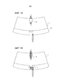
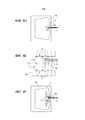
фигуры 1a и 1b ниже схематически показывают вид спереди лобового окна автомобиля, оснащенного двумя компонентами, описанными выше;Figures 1a and 1b below schematically show a front view of a windshield of an automobile equipped with the two components described above;
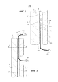
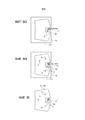
фигуры 2 и 3 показывают детализированный вид в сечении участков многослойного остекления, в которые вставлен каждый из этих двух компонентов;Figures 2 and 3 show a detailed cross-sectional view of portions of laminated glazing into which each of the two components is inserted;
фигура 4 схематически показывает сечение в плоскости A-A с фигуры 3;figure 4 schematically shows a section in the plane A-A from figure 3;
фигура 5 схематически показывает способ согласно уровню техники для вставки компонента с толщиной более 0,2 мм в многослойное остекление;Figure 5 schematically shows a prior art method for inserting a component with a thickness greater than 0.2 mm into a laminated glazing;
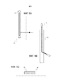
фигуры 6a, 6b и 6c и 7a и 7b схематически показывают два закладных компонента: кабель, соединяющий видеокамеру, и компонент, содержащий светодиоды (LED), соответственно;Figures 6a, 6b and 6c and 7a and 7b schematically show two embedded components: a cable connecting a video camera and a component containing light-emitting diodes (LEDs), respectively;
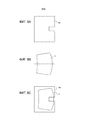
фигуры 8a-i иллюстрируют различные этапы способа по изобретению; иFigures 8a-i illustrate various steps of the method according to the invention; and
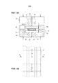
фигуры 9a и 9b показывают способ получения закладного компонента путем прессования в форме, соответственно в сечении A-A и в виде сверху.Figures 9a and 9b show a method for producing an insert by compression molding, respectively in section A-A and in plan view.
Согласно фигурам 1a и 1b, закладные компоненты 10 и 11, показаны в верхнем и нижнем положении, соответственно, на автомобильном лобовом стекле 1.According to Figures 1a and 1b, the
Фигура 1a показывает изделие таким, как он видится водителю транспортного средства. Участки трафаретной печати 20, 21 на стороне IV лобового стекла скрывают часть закладных компонентов 10 и 11 от глаз пассажиров автомобиля, но оставляют видимыми из салона транспортного средства их полезные участки. Эти участки трафаретной печати намеренно показаны прозрачными на фигуре 1b, чтобы можно было видеть закладные компоненты 10 и 11, вставленные между стеклянными листами.Figure 1a shows the product as seen by the vehicle driver. The
Закладной компонент 10 представляет собой плоский кабель, позволяющий соединить видеокамеру, находящуюся внутри транспортного средства, с ее процессором, который находится в другом месте салона транспортного средства. Кабель находится в верхнем центральном положении на лобовом стекле и снабжен разъемом на обоих концах.The embedded
Закладной компонент 11 представляет собой набор из трех диодов, находящийся на уровне нижней полосы лобового стекла, этот набор может применяться для сигнализации об особых условиях вождения. Диоды и их электронная схема управления нанесены на тонкую гибкую печатную плату (FPC). Диоды, их электронная схема управления и FPC соединены с ленточным кабелем, снабженным разъемом на конце.The embedded
Фигуры 2 и 3 более детально иллюстрируют различные компоненты и способ, с помощью которого они вставлены в PVB.Figures 2 and 3 illustrate in more detail the various components and the manner in which they are inserted into the PVB.
Фигура 2 представляет собой частичный схематический вид в разрезе лобового окна 1, содержащего светодиодный (LED) компонент 11, который находится на уровне нижней полосы остекления. Лобовое окно 1 состоит из внутреннего стеклянного листа 2 и наружного стеклянного листа 3, соединенных друг с другом посредством листа адгезионной вставки 4 (поливинилбутираль, PVB). На фигуре можно видеть: 1) LED 11a, находящийся напротив отверстия 21a в трафаретной печати 21 на стороне IV лобового окна, 2) FPC 11b, несущую электронные компоненты 11c, и 3) источник питания и управляющий кабель 11d, который выходит из остекления 1 и который снабжен разъемом 11e. Этот кабель 11d может входить внутрь салона для соединения с электрической сетью транспортного средства. Далее, лобовое окно 1 имеет трафаретную печать 21' на стороне II, функцией которой является, в частности, скрыть капли адгезива, склеивающие лобовое окно с проемом кузова, при рассматривании снаружи транспортного средства.Figure 2 is a partial schematic sectional view of a
Фигура 3 представляет собой частичный схематический вид в разрезе лобового окна 1, содержащего экранированный кабель 10, использующийся для подключения видеокамеры за зеркалом заднего вида. Можно видеть сам кабель 10a, нижний разъем 10b, позволяющий подсоединить видеокамеру в салоне транспортного средства, и верхний разъем 10c, позволяющий подсоединить контроллер видеокамеры. Кабель 10a может входить внутрь салона, чтобы подсоединиться к электрической схеме транспортного средства. Остальные элементы лобового окна 1 такие же, какие были описаны в связи с фигурой 2.Figure 3 is a partial schematic sectional view of a
Фигура 4 представляет собой сечение фигуры 3 плоскостью A-A. Плоский кабель 10a, подсоединяющий видеокамеру, состоит из проводов разного типа 10d. Их функция не будет здесь описываться в деталях. Материал 10e является диэлектриком, а материал 10f экранирующим материалом.Figure 4 is a sectional view of Figure 3 along the plane A-A. The
Фигура 5 показывает тот же вид, что и на фигуре 4, чтобы проиллюстрировать способ введения плоского кабеля 10a в многослойное остекление 1 в соответствии с уровнем техники. Численные позиции, приведенные на фигуре 4, не повторяются, поскольку они не нужны для понимания способа.Figure 5 shows the same view as Figure 4 to illustrate the method of inserting a
Толстый плоский кабель 10a толщиной 0,4 мм вставлен в многослойное лобовое окно 1. Сборка реализуется посредством двух листов PVB 4a и 4b толщиной, соответственно, 0,76 и 0,38 мм, которые плотно пригнаны вокруг плоского кабеля 10a, который вставлен между двумя листами PVB 4c и 4b толщиной 0,38 мм.A thick
Таким образом, в любой точке изделия наблюдаемая толщина системы "PVB 4+плоский кабель 10a" составляет около 1,1 мм, что позволяет решить большинство классических проблем, упомянутых выше.Thus, at any point in the product, the observed thickness of the "
Далее, при автоклавировании PVB будет нагрет до относительно высокой температуры (выше 100°C), в результате чего он размягчится и сможет течь. При этом следует отметить, что границы раздела между разными частями PVB исчезают, и PVB будет, так сказать, "зарубцовываться", чтобы образовать после автоклавирования однородную сплошную пленку толщиной 1,1 мм.Further, during autoclaving, the PVB will be heated to a relatively high temperature (above 100 ° C), as a result of which it will soften and be able to flow. It should be noted here that the interfaces between the different parts of the PVB disappear and the PVB will, so to speak, "heal up" in order to form, after autoclaving, a uniform continuous film with a thickness of 1.1 mm.
По окончании автоклавирования изделие является идеально прозрачным, лишь небольшое оптическое искажение при пропускании может появиться вблизи кабеля.At the end of autoclaving, the product is perfectly transparent, only a slight optical distortion during transmission may appear near the cable.
К сожалению, остаются другие названные выше проблемы, связанные с множественностью границ раздела PVB/PVB, например, остается риск возникновения визуально наблюдаемых дефектов, в частности, из-за захвата пыли.Unfortunately, the other above-mentioned problems associated with the multiplicity of PVB / PVB interfaces remain, for example, the risk of visually observable defects remains, in particular due to dust entrapment.
Фигуры 6a, 6b и 6c и 7a и 7b схематически показывают два закладных компонента, а именно кабель, соединяющий видеокамеру, и компонент, содержащий светодиоды (LED), соответственно.Figures 6a, 6b and 6c and 7a and 7b schematically show two embedded components, namely a cable connecting a video camera and a component containing light-emitting diodes (LEDs), respectively.
Согласно этим фигурам, компоненты закладываются в лист PVB с ограниченными поперечными размерами и простой, типично прямоугольной, геометрии. Толщина закладного компонента равна толщине листа PVB в оконном стекле, чаще всего 0,76 мм.According to these figures, the components are embedded in a PVB sheet with limited transverse dimensions and simple, typically rectangular, geometry. The thickness of the embedded component is equal to the thickness of the PVB sheet in the glass pane, usually 0.76 mm.
На фигуре 6a закладной компонент 10, применяющийся для подсоединения видеокамеры, показан в виде спереди. Компонент 10 представляет собой относительно толстый кабель, толщина которого обычно больше 0,1 мм, снабженный разъемом на каждом его конце, как подробно говорилось выше. Как лучше видно на фигуре 6b (вид в разрезе), кабель входит в лист PVB 4d через его кромочную поверхность и выходит другим концом через поверхность листа PVB 4d, проходя через остекление сквозь отверстие, высверленное во внутреннем стекле (не показано), как описано в связи с фигурой 3. Стрелка на фигуре 6a указывает место, где компонент выходит из листа PVB 4d.In figure 6a, the
Фигура 6c показывает сечение закладного компонента 10, выполненное в части, где кабель еще утоплен в листе PVB 4d.Figure 6c shows a cross-sectional view of the embedded
На фигуре 7a закладной компонент 11 для применения в качестве LED, показан в виде спереди. Компонент 11 состоит из платы FPC с закрепленными на ее поверхности электронными компонентами и светодиодами, и кабеля, снабженного разъемом, как подробно пояснялось в связи с фигурой 2. Все это закладывается в лист PVB 4d постоянной толщины, обычно 0,76 мм. Кабель выходит из листа PVB 4d через кромочную поверхность последнего и проходит от нее наружу, как лучше видно на фигуре 7b, показывающей поперечный разрез. Конец кабеля снабжен разъемом для соединения с электропроводкой транспортного средства.In Figure 7a, an
Далее на фигурах 8a-i более конкретно описывается способ установки закладного компонента в многослойное остекление согласно изобретению.In the following, FIGS. 8a-i more specifically describe a method for installing an embedded component in a multi-layer glazing according to the invention.
Фигура 8a показывает основной лист PVB 4e, подготовленный независимо путем вырезания в нем окошка, предназначенного для размещения закладного компонента. Для этого применяется автоматическая режущая система, которая состоит из стола и лезвия, удерживаемого поворотным инструментом, который сам закреплен на устройстве, позволяющем горизонтальное перемещение (в плоскости X-Y), а именно, на каретке, установленной на мосту, что позволяет резать лист PVB локально. Комбинируя различные перемещения, можно заставить лезвие следовать любой траектории резания.Figure 8a shows a
Фигура 8b показывает отдельное внутреннее стекло 2 с его выпуклой поверхностью, обращенной вверх. Альтернативно, может иметься отдельное наружное стекло с вогнутой поверхностью, направленной вверх.Figure 8b shows a separate
Фигура 8c показывает лист PVB 4e, который был разрезан заранее (этап 1), установленный на внутренний стеклянный лист 2, причем лист PVB 4e центрирован относительно внутреннего стекла 2.Figure 8c shows a
Фигура 8d показывает закладной компонент 11, 4d, размещенный внутри окошка, вырезанного в листе PVB 4e на этапе 1.Figure 8d shows an
Фигура 8e показывает точки соединения 5 закладного компонента 11, 4d и листа PVB с разрезом, 4e, с внутренним стеклом 2 вблизи окошка, чтобы боковые стенки a) окошка, вырезанного в листе PVB 4e, и b) закладного компонента 11, 4d оставались соприкасающимися, т.е., находились в хорошем контакте друг с другом. Фигура 8f является изображением фигуры 8e в уменьшенном масштабе.Figure 8e shows the connection points 5 of the
Фигура 8g показывает наружное стекло 3, установленное (уложенное, выровненное по центру) на сборку, состоящую из внутреннего стекла 2+лист PVB 4e+закладной компонент 11, 4d, причем два последних прикреплены точечным соединением 5 к внутреннему стеклу 2.Figure 8g shows an
Фигура 8h показывает точки соединения 6 полученной сборки (внутреннее стекло 2+лист PVB 4e+закладной компонент 11, 4d+наружное стекло 3), предусмотренные для того, чтобы различные элементы оставались надежно закрепленными друг с другом в остальной части процесса.Figure 8h shows the connection points 6 of the resulting assembly (
Фигура 8i показывает удаление лишнего PVB 4e вокруг остекления путем обрезки по периметру, например, ножом. Без этого этапа можно обойтись, если этап вырезания окошка в листе PVB 4e (фигура 8a) дополняется полной обрезкой листа до размеров остекления.Figure 8i shows the removal of
Далее описываются методы изготовления закладных компонентов.The following describes the manufacturing methods for embedded components.
Для закладки компонентов в PVB при одновременном контроле толщины сборки можно использовать различные методы. Укажем несколько неограничивающих примеров осуществления. Эти примеры базируются на трех разных методах: формование, экструзия или литье под давлением. Эти методы или их комбинации позволяют осуществить подходящую закладку.Various methods can be used to insert components into PVB while controlling assembly thickness. Here are some non-limiting examples of implementation. These examples are based on three different methods: molding, extrusion or injection molding. These methods, or combinations of them, allow for a suitable setting.
Метод формования: согласно фигурам 9a и 9b, один возможный вариант осуществления состоит в использовании пресс-формы, состоящей из двух дополняющих частей 30 и 31 и содержащей выпоры 32 и нагревательный контур 33, через который течет масло, в форму укладывают друг на друга два листа PVB, 4d1 и 4d2, между которыми помещен закладываемый компонент, а именно, плоский кабель 10a. Толщины листов PVB 4d1 и 4d2, введенных в пресс-форму, подбирают так, чтобы полный объем PVB был в небольшом избытке. Затем к каждой полуформе 30 и 31 прикладывают давление, чтобы прижать их друг к другу, затем активируют циркуляцию горячего масла в нагревательном контуре 33, чтобы размягчить PVB. Давление между двумя полуформами можно приложить с помощью тарельчатых пружин или же посредством гидравлического или пневматического усилия. Внутренность формы и плоскость разъема покрыты тефлоновым покрытием, чтобы предотвратить прилипание PVB к стенкам формы. Molding method : according to Figures 9a and 9b, one possible embodiment is to use a mold consisting of two
Когда PVB размягчается, он сплющивается под действием давления, приложенного между полуформами 30 и 31, и заполняет оставшееся свободным пространство с обеих сторон закладываемого компонента. После этой операции небольшой избыток PVB заполняет выпоры 32, предусмотренные в пресс-форме. Выпоры 32 позволяет использовать PVB в небольшом избытке в пресс-форме, чтобы быть уверенным, что все зазоры будут заполнены PVB, а также, чтобы гарантировать, что этот избыточный материал будет удален (через выпоры 32), чтобы обеспечить хорошо контролируемую толщину закладного компонента.When the PVB softens, it collapses under the pressure applied between
В случае захвата пузырьков воздуха можно просто ввести пресс-форму в вакуумную камеру перед нагреванием формы.In the case of trapping air bubbles, you can simply insert the mold into the vacuum chamber before heating the mold.
Метод экструзии: другой возможный вариант осуществления состоит в использовании фильеры. Можно представить себе трехстадийный способ: 1) первый лист PVB (4d1 на фигуре 9a) можно поместить на дно формы (охватывающая часть 30 на фигуре 9a), используя фильеру, затем 2) компонент 10a можно разместить на этом первом листе PVB 4d1, наконец, 3) второй слой PVB 4d2 в небольшом избытке можно нанести на систему "первый лист PVB 4d1+компонент 10a". Для завершения сборки ее можно дополнить помещением под давление охватываемой части формы 31 и затем, аналогично предыдущему способу, можно обеспечить калиброванную толщину закладного компонента. Можно, что проще, не использовать охватываемую часть 31, а просто удалить лишний PVB, проводя ножом над охватывающей частью формы. В случае захвата пузырьков воздуха одно усовершенствование могло бы состоять в осуществлении экструзии в вакуумной камере. Extrusion method: Another possible embodiment is to use a die. One can imagine a three-step method: 1) the first PVB sheet (4d1 in Figure 9a) can be placed on the bottom of the mold (
Метод заливки под давлением: другой вариант осуществления состоит в прямой инжекции PVB вокруг компонента. При применении этого метода можно столкнуться с двумя трудностями: 1) во-первых, необходимо, чтобы компонент мог выдерживать очень высокие давления, встречающиеся в литьевой пресс-форме из-за высокой вязкости PVB, 2) вторая сложность связана с выдерживанием компонента в литьевой пресс-форме так, чтобы он не смещался во время подачи жидкого полимера.Injection molding method : Another embodiment is direct injection of PVB around the component. When applying this method, two difficulties can be encountered: 1) first, it is necessary that the component can withstand the very high pressures encountered in the injection mold due to the high viscosity of PVB, 2) the second difficulty is related to the holding of the component in the injection press -shaped so that it does not move while feeding the liquid polymer.
Одна предпочтительная комбинация могла бы состоять в наличии двухместной пресс-формы, как в случае формы, подробно описанной выше, но у которой верхняя охватываемая часть 31 была бы оснащена впрыскивающими соплами. Способ мог бы, например, состоять во введении первого листа PVB 4d1, который заполнял бы охватывающую часть формы, затем в закреплении введенного туда компонента 10a, например, соединением (аналогично методу, который позволяет закрепить закладной компонент на внутреннем стекле, как показано на фигура 8e), затем в закрывании литьевой пресс-формы и инжекции PVB.One preferred combination would be to have a double mold, as in the case of the mold detailed above, but in which the upper
Настоящее изобретение выгодно во многих отношениях:The present invention is beneficial in many ways:
- Метод подходит для любых компонентов (относительно малой толщины): можно получить промежуточный продукт (компонент, покрытый PVB, находящимся в виде листа хорошо контролируемой толщины) с большим числом компонентов, при условии, что один из их размеров (толщина) мал по сравнению с другими. Таким образом, в описанных случаях сборку компонента "LED" можно осуществить тем же способом, что и компонента "экранированный кабель". Можно представить себе и другие продукты, такие как текстильные изделия, факультативно на основе оптических волокон, которые позволяют освещать большую часть остекления или же вполне определенные зоны; датчики; чипы радиочастотной идентификации и т.д.- The method is suitable for all components (relatively low thickness): an intermediate product (component coated with PVB in the form of a sheet of well controlled thickness) with a large number of components can be obtained, provided that one of their dimensions (thickness) is small compared to others. Thus, in the described cases, the assembly of the "LED" component can be accomplished in the same manner as the "shielded cable" component. Other products can be envisioned, such as textiles, optionally based on optical fibers, which can illuminate most of the glazing or well defined areas; sensors; RFID chips, etc.
В случае, когда толщина компонента больше 0,76 мм (толщины стандартного листа PVB), можно предусмотреть изготовление закладного компонента размером 2·0,76 мм=1,52 мм и сборку его с двумя листами PVB, уложенными друг на друга.In the case when the thickness of the component is more than 0.76 mm (the thickness of a standard PVB sheet), it is possible to envisage making an embedded component with a size of 2 · 0.76 mm = 1.52 mm and assembling it with two PVB sheets stacked on top of each other.
- Метод является продуктивным: цель производственной линии состоит в том, чтобы быть производительной, а не создавать узкие места. Понятно, что способы известного уровня техники, описанные выше, не годятся для поточного производства. Напротив, способ, описанный в настоящем изобретении, совместим с таким производством. В частности, время, теряемое по сравнению со сборкой стандартного продукта без закладного компонента, заключается в 1) помещении компонента в заранее вырезанное окошко в листе PVB и 2) соединение периферии этих двух компонентов с наружным стеклом (как схематически показано на фигуре 8e). Эта операция совместима со скоростью производственной линии, поскольку a) можно опустить операцию, в которой обрезается часть листа PVB, выступающая за границы остекления, включив эту операцию обрезки в тот же цикл, какой использовался для вырезания окошка в листе PVB, и b) можно разработать инструмент, позволяющий получать несколько точек соединения за одну операцию.- The method is productive: the goal of the production line is to be productive, not to create bottlenecks. It will be understood that the prior art methods described above are not suitable for in-line production. On the contrary, the method described in the present invention is compatible with such production. Specifically, the time lost compared to assembling a standard product without an embedded component consists in 1) placing the component in a pre-cut window in the PVB sheet and 2) connecting the periphery of these two components to the outer glass (as schematically shown in Figure 8e). This operation is compatible with the speed of the production line since a) the operation in which the part of the PVB sheet extending beyond the glazing is cut can be omitted by including this cut operation in the same cycle as was used to cut a window in the PVB sheet, and b) it is possible to design a tool that allows you to obtain multiple connection points in one operation.
- Низкая отбраковка по качеству: по сравнению с вышеупомянутым уровнем техники, технология с использованием закладного компонента уменьшает число листов PVB и границ раздела между ними, тем самым снижая вероятность захвата пыли или волокон (что приводило бы к отбраковке изделий из-за визуальных дефектов), после того как указанные продукты достигнут полной прозрачности в конце операции сборки (дегазация, герметизация кромок, автоклавирование).- Low rejection in quality: compared with the above-mentioned prior art, the technology using the embedded component reduces the number of PVB sheets and the interfaces between them, thereby reducing the likelihood of dust or fiber entrapment (which would lead to rejection of products due to visual defects), after said products have reached full transparency at the end of the assembly operation (degassing, edge sealing, autoclaving).
Наконец, боковой контакт между листами PVB имеет место только с трех сторон, что минимизирует риск образования пузырей во время операции сборки.Finally, side contact between PVB sheets only occurs on three sides, which minimizes the risk of blistering during assembly.
Claims (3)
Applications Claiming Priority (3)
| Application Number | Priority Date | Filing Date | Title |
|---|---|---|---|
| FR1653743 | 2016-04-27 | ||
| FR1653743A FR3050685B1 (en) | 2016-04-27 | 2016-04-27 | PROCESS FOR ASSEMBLING A LAMINATED WINDOWS INCLUDING AN OVERMOLDED COMPONENT |
| PCT/FR2017/050969 WO2017187075A1 (en) | 2016-04-27 | 2017-04-24 | Method for assembling laminated glazing comprising an overmoulded component |
Publications (3)
| Publication Number | Publication Date |
|---|---|
| RU2018141384A RU2018141384A (en) | 2020-05-28 |
| RU2018141384A3 RU2018141384A3 (en) | 2020-07-10 |
| RU2742083C2 true RU2742083C2 (en) | 2021-02-02 |
Family
ID=56322147
Family Applications (1)
| Application Number | Title | Priority Date | Filing Date |
|---|---|---|---|
| RU2018141384A RU2742083C2 (en) | 2016-04-27 | 2017-04-24 | Multilayer glazing comprising an embedded component, and use thereof |
Country Status (14)
| Country | Link |
|---|---|
| US (1) | US11034615B2 (en) |
| EP (1) | EP3448824B1 (en) |
| JP (1) | JP7004669B2 (en) |
| KR (1) | KR102382792B1 (en) |
| CN (1) | CN109071336B (en) |
| BR (1) | BR112018070782A2 (en) |
| CA (1) | CA3020480A1 (en) |
| ES (1) | ES2899948T3 (en) |
| FR (1) | FR3050685B1 (en) |
| HU (1) | HUE056742T2 (en) |
| MX (1) | MX2018013067A (en) |
| PL (1) | PL3448824T3 (en) |
| RU (1) | RU2742083C2 (en) |
| WO (1) | WO2017187075A1 (en) |
Families Citing this family (4)
| Publication number | Priority date | Publication date | Assignee | Title |
|---|---|---|---|---|
| JP6904338B2 (en) * | 2016-04-27 | 2021-07-14 | Agc株式会社 | Window members and vehicle window glass |
| CO2018000469A1 (en) * | 2017-11-30 | 2018-04-30 | Agp America Sa | Automotive laminate with invisible solid edge substrate compensation layer |
| GB201814347D0 (en) * | 2018-09-04 | 2018-10-17 | Pilkington Group Ltd | Electrical device, interlayer ply including an electrical device and methods for making said electrical device and interlayer ply |
| EP3925774A1 (en) * | 2020-06-17 | 2021-12-22 | Inalfa Roof Systems Group B.V. | Functional lighting in an obscuration band of a vehicle glazing |
Citations (9)
| Publication number | Priority date | Publication date | Assignee | Title |
|---|---|---|---|---|
| US5384346A (en) * | 1992-05-08 | 1995-01-24 | Hoechst Ag | Polyvinyl butyrals having improved thermal stability and light resistance |
| RU2162064C2 (en) * | 1998-12-23 | 2001-01-20 | Открытое акционерное общество "Саратовский институт стекла" | Method of producing multilayer laminated glass of complicated configurations |
| WO2004009349A1 (en) * | 2002-07-19 | 2004-01-29 | Pilkington Plc. | Laminated glazing panel |
| WO2004037532A1 (en) * | 2002-10-22 | 2004-05-06 | Opaci Lam Pty Ltd | Laminated glass |
| DE102007012571A1 (en) * | 2006-07-15 | 2008-01-17 | Volkswagen Ag | Transparent indicator device for displaying information, comprises transparent disc of motor vehicle, which has organic light emitting diode display arranged in or on disc, where display is conducted in form of module |
| RU2315735C2 (en) * | 2001-12-27 | 2008-01-27 | Солютиа Инк. | Method and device for manufacture of laminated glass |
| EP1933079A1 (en) * | 2006-12-14 | 2008-06-18 | AGC Flat Glass Europe SA | Illuminated panel |
| US7745838B2 (en) * | 2003-01-10 | 2010-06-29 | Agc Glass Europe | Glazing comprising electronics elements |
| RU2423329C2 (en) * | 2006-02-14 | 2011-07-10 | Пилкингтон Отомоутив Лимитед | Sheet glass |
Family Cites Families (15)
| Publication number | Priority date | Publication date | Assignee | Title |
|---|---|---|---|---|
| US3881043A (en) * | 1971-06-21 | 1975-04-29 | Ppg Industries Inc | Laminated safety windshields |
| EP0267331A1 (en) * | 1986-11-10 | 1988-05-18 | Donnelly Corporation | Illuminated panel assembly |
| WO2004106056A1 (en) * | 2003-05-28 | 2004-12-09 | Döppner Bauelemente GmbH & Co. KG | Method and device for producing composite elements, and resulting composite element |
| DE10325402A1 (en) * | 2003-05-28 | 2004-12-23 | Döppner Bauelemente GmbH & Co. KG | Composite assembly of at least two glass panes with a film insert and thermoplastic film between them, e.g. for cladding balconies, is bonded together within a flexible bag which can be evacuated and placed within an autoclave |
| FR2895781B1 (en) * | 2005-12-29 | 2014-10-10 | Saint Gobain | LIGHT STRUCTURE COMPRISING AT LEAST ONE ELECTROLUMINESCENT DIODE, ITS MANUFACTURE AND ITS APPLICATIONS |
| EP1979160A1 (en) * | 2006-01-25 | 2008-10-15 | AGC Flat Glass Europe SA | Automotive glazing |
| BR112012016402B1 (en) * | 2009-12-31 | 2020-02-04 | Saint Gobain | laminated pane, transport vehicle, construction or any structure incorporating such a laminated pane, process of making such a laminated pane and application of such a laminated pane |
| US8752976B2 (en) * | 2011-07-24 | 2014-06-17 | Cree, Inc. | Light fixture with co-formed plenum component |
| FR2986854B1 (en) * | 2012-02-13 | 2014-02-14 | Saint Gobain | GLAZING LIGHTING |
| FR2996802B1 (en) * | 2012-10-12 | 2014-11-21 | Saint Gobain | GLAZING SHEET |
| FR2996803B1 (en) * | 2012-10-12 | 2014-11-21 | Saint Gobain | MANUFACTURING LAMINATED GLAZING WITH ELECTRICAL CONDUCTOR |
| JP6173470B2 (en) * | 2012-10-19 | 2017-08-02 | サン−ゴバン グラス フランスSaint−Gobain Glass France | Polymer vehicle window with LED assembly |
| FR3003196B1 (en) * | 2013-03-15 | 2018-01-19 | Saint-Gobain Glass France | GLAZING COMPRISING A TRANSPARENT SCREEN. |
| CN104780632B (en) * | 2015-04-01 | 2017-04-12 | 宁波山迪光能技术有限公司 | Heatable glass and manufacturing method thereof |
| CN204808778U (en) * | 2015-07-13 | 2015-11-25 | 江苏银晶光电科技发展有限公司 | Take glass display screen of hidden sculpture circuit conductive film |
-
2016
- 2016-04-27 FR FR1653743A patent/FR3050685B1/en active Active
-
2017
- 2017-04-24 ES ES17725306T patent/ES2899948T3/en active Active
- 2017-04-24 JP JP2018556826A patent/JP7004669B2/en active Active
- 2017-04-24 CN CN201780026254.2A patent/CN109071336B/en active Active
- 2017-04-24 BR BR112018070782A patent/BR112018070782A2/en active Search and Examination
- 2017-04-24 CA CA3020480A patent/CA3020480A1/en not_active Abandoned
- 2017-04-24 PL PL17725306T patent/PL3448824T3/en unknown
- 2017-04-24 EP EP17725306.9A patent/EP3448824B1/en active Active
- 2017-04-24 KR KR1020187030710A patent/KR102382792B1/en active IP Right Grant
- 2017-04-24 WO PCT/FR2017/050969 patent/WO2017187075A1/en active Application Filing
- 2017-04-24 MX MX2018013067A patent/MX2018013067A/en unknown
- 2017-04-24 US US16/096,971 patent/US11034615B2/en active Active
- 2017-04-24 HU HUE17725306A patent/HUE056742T2/en unknown
- 2017-04-24 RU RU2018141384A patent/RU2742083C2/en active
Patent Citations (9)
| Publication number | Priority date | Publication date | Assignee | Title |
|---|---|---|---|---|
| US5384346A (en) * | 1992-05-08 | 1995-01-24 | Hoechst Ag | Polyvinyl butyrals having improved thermal stability and light resistance |
| RU2162064C2 (en) * | 1998-12-23 | 2001-01-20 | Открытое акционерное общество "Саратовский институт стекла" | Method of producing multilayer laminated glass of complicated configurations |
| RU2315735C2 (en) * | 2001-12-27 | 2008-01-27 | Солютиа Инк. | Method and device for manufacture of laminated glass |
| WO2004009349A1 (en) * | 2002-07-19 | 2004-01-29 | Pilkington Plc. | Laminated glazing panel |
| WO2004037532A1 (en) * | 2002-10-22 | 2004-05-06 | Opaci Lam Pty Ltd | Laminated glass |
| US7745838B2 (en) * | 2003-01-10 | 2010-06-29 | Agc Glass Europe | Glazing comprising electronics elements |
| RU2423329C2 (en) * | 2006-02-14 | 2011-07-10 | Пилкингтон Отомоутив Лимитед | Sheet glass |
| DE102007012571A1 (en) * | 2006-07-15 | 2008-01-17 | Volkswagen Ag | Transparent indicator device for displaying information, comprises transparent disc of motor vehicle, which has organic light emitting diode display arranged in or on disc, where display is conducted in form of module |
| EP1933079A1 (en) * | 2006-12-14 | 2008-06-18 | AGC Flat Glass Europe SA | Illuminated panel |
Also Published As
| Publication number | Publication date |
|---|---|
| RU2018141384A (en) | 2020-05-28 |
| MX2018013067A (en) | 2019-01-24 |
| EP3448824A1 (en) | 2019-03-06 |
| CA3020480A1 (en) | 2017-11-02 |
| WO2017187075A1 (en) | 2017-11-02 |
| US11034615B2 (en) | 2021-06-15 |
| US20190077704A1 (en) | 2019-03-14 |
| FR3050685A1 (en) | 2017-11-03 |
| CN109071336A (en) | 2018-12-21 |
| BR112018070782A2 (en) | 2019-02-05 |
| KR102382792B1 (en) | 2022-04-06 |
| KR20180136963A (en) | 2018-12-26 |
| EP3448824B1 (en) | 2021-10-27 |
| PL3448824T3 (en) | 2022-01-03 |
| CN109071336B (en) | 2022-04-08 |
| JP7004669B2 (en) | 2022-01-21 |
| FR3050685B1 (en) | 2021-02-12 |
| RU2018141384A3 (en) | 2020-07-10 |
| HUE056742T2 (en) | 2022-03-28 |
| JP2019521056A (en) | 2019-07-25 |
| ES2899948T3 (en) | 2022-03-15 |
Similar Documents
| Publication | Publication Date | Title |
|---|---|---|
| RU2742083C2 (en) | Multilayer glazing comprising an embedded component, and use thereof | |
| KR102396050B1 (en) | Luminescent signaling glazing, vehicle equipped with same and manufacturing | |
| US9925915B2 (en) | Luminous signaling glazing unit, vehicle incorporating same and manufacture | |
| CN107848270B (en) | Composite glass plate with multi-layer composite layer and manufacturing method thereof | |
| CN104553193B (en) | Multiple layer polymer middle layer with melt fractured surface | |
| CN105722679B (en) | Manufacture the method with the compound glass layered product of conductive structure of insertion | |
| EP2401639B1 (en) | Laminated glass diffused lighting panel and method of manufacturing it | |
| JP5925691B2 (en) | Glazing with ultrasonically incorporated conductors | |
| US11325353B2 (en) | Composite pane with an electrical load | |
| EP2635433B1 (en) | Laminated inorganic and organic glass diffused lighting panel | |
| CN108260351B (en) | Composite glass sheet and method of manufacturing a composite glass sheet | |
| JP2019521056A5 (en) | ||
| CN100391731C (en) | Laminated glass sheet with a laminated film | |
| CN111225794A (en) | Composite glass plate and method for manufacturing same | |
| JPWO2019150037A5 (en) | ||
| EP4066043A1 (en) | Laminated glazing for projecting an image from a head-up display (hud) | |
| US11812557B2 (en) | Electrical device, interlayer ply including an electrical device and methods for making said electrical device and interlayer ply | |
| JP2023011440A (en) | Method for manufacturing laminated glass for vehicle window | |
| KR20200128423A (en) | Composite pane with functional elements and lighting | |
| KR20240121735A (en) | Composite interlayer for bonded panels, bonded panels, and methods for manufacturing them | |
| EP4373668A1 (en) | Windows with laminated glass layers | |
| CN116997463A (en) | Laminated glazing |